MORE HANDBOOKS ARE ON THEIR WAY! We will let you know when they get here.
×


pompey2
-
Posts
511 -
Joined
-
Last visited
Content Type
Profiles
Forums
Gallery
Events
Everything posted by pompey2
-
I normally go 50/50 PVA and water. And trim a day later
-
 Hi Chris Nice to see another Pompey lad on the site. And as well as that in common I am also modelling the Victory, and have been for some time!! Obviously it had to be done at some time. I have been looking through your log, it looks like a great job, especially if this is a first, you should be proud. I will have to keep up to date with your progress, Anyway, time to get down to the Still and West Nick
- 117 replies
-
- 2
-

-
- victory
- billing boats
- (and 1 more)
-
Gil, A great job in every aspect. I have been keep track of your build for quite a while and it has been a great source of guidance. she looks just great. Nick
- 755 replies
-
- 2
-
-
- finished
- caldercraft
- (and 1 more)
-
I use this know quite a bit. Often for the first ratline to shroud knot being more secure that a clove hitch. In those instances you dont have a free end (ie spar end) to drop the know over. But it is pretty easy to tie the clove hitch first, then pass one end (of the ratline in this example) back through the knot. I dont have access to anything at the moment to show where the line passes through the knot but the animated knots site shows it. Nick
-
Design and Build a Custom Work Station
pompey2 replied to pompey2's topic in Modeling tools and Workshop Equipment
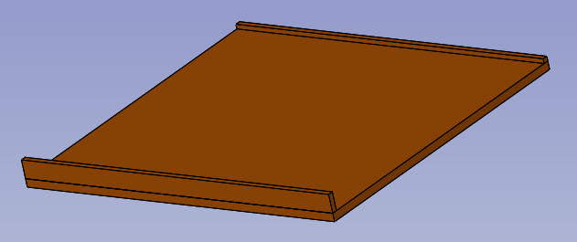
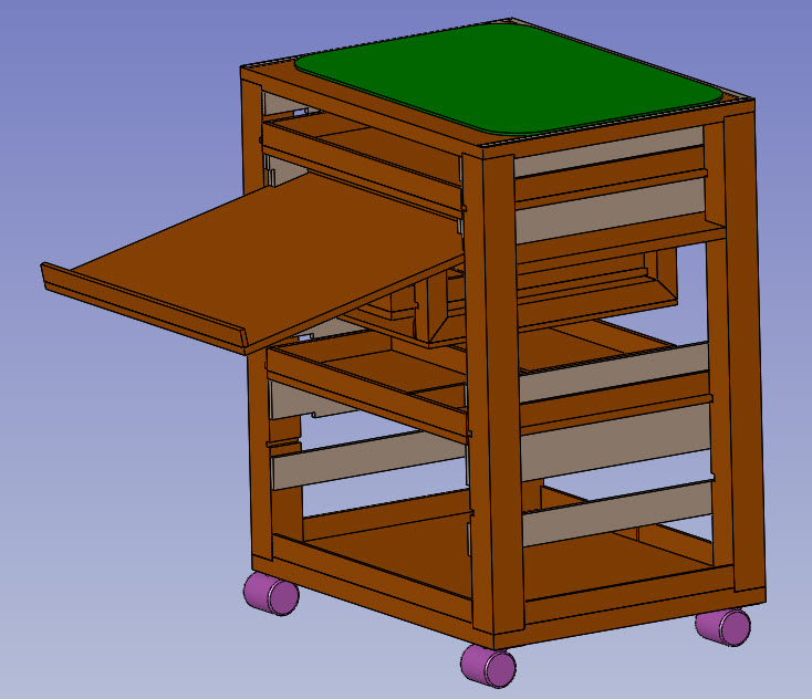
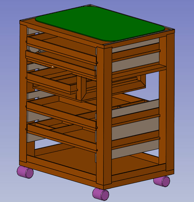
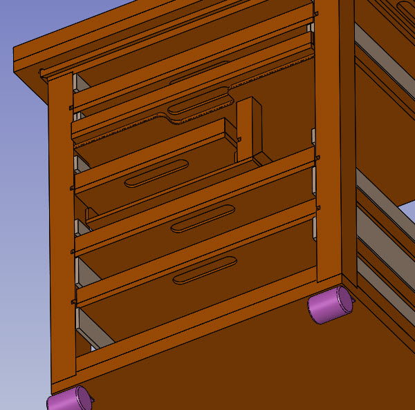
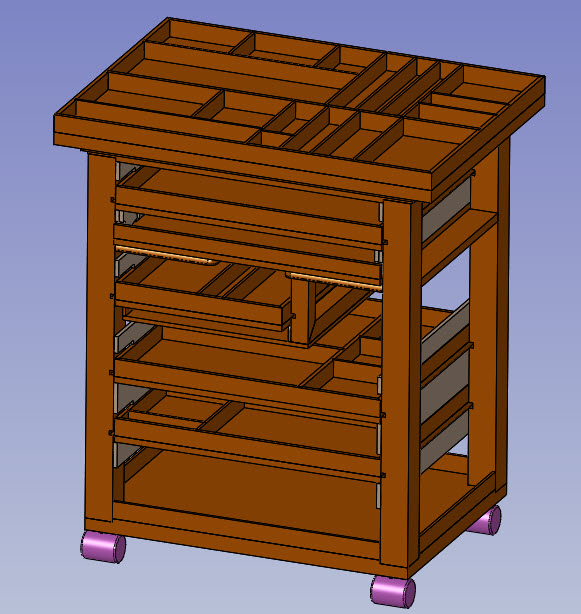
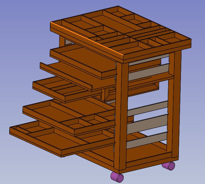
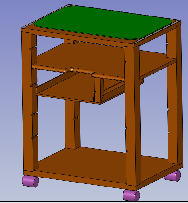
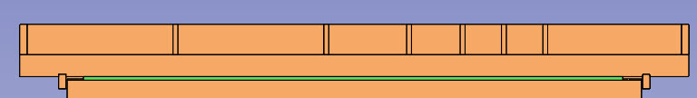
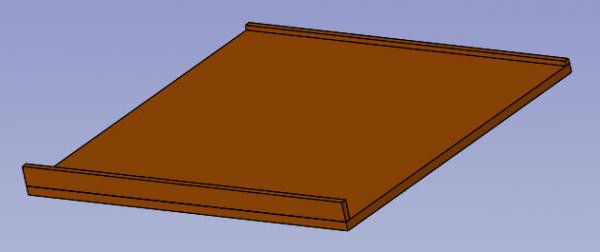
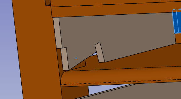
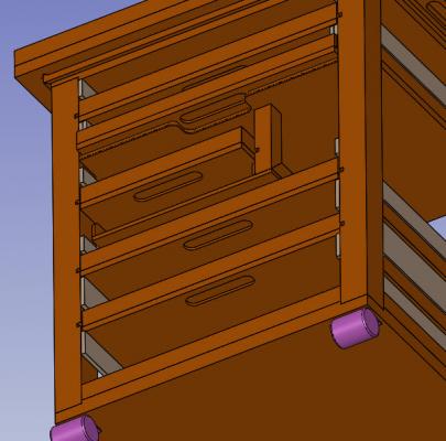
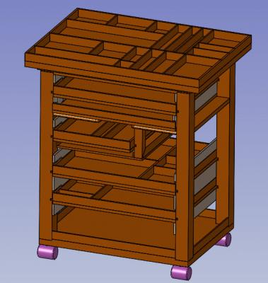
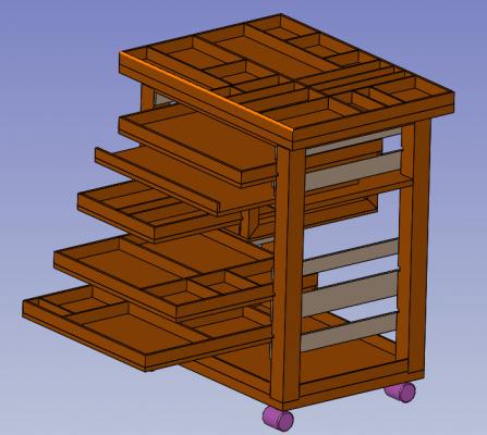
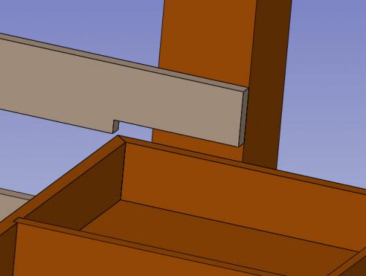
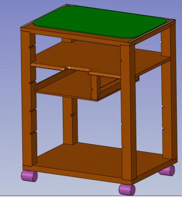
To continue I put a rail around the base for bulkier/heavier items I want to have a shelf that i can use for reference material - ship manual for instance. I am going to have it sit on top of the fixed shelf and it will still slide out. This is the shelf with a lip on front to hold a book. The guides above the shelf have a 'special' shaped cut away. That allows the shelf to slide out and close snuggly And then when pulled out can drop down and be held securely All the trays/shelves have finger cut out below I have compartmentalised the other trays. Which pretty much completes the design stage. Here is the finished item With trays slid out And with the top tray removed to allow use of the cutting mat surface Now to get onto the Building. That will be my xmas project So I will follow up here once there is progress to show Nick

-
Design and Build a Custom Work Station
pompey2 replied to pompey2's topic in Modeling tools and Workshop Equipment
Tom Sure, i dont really want to sit 'at' it. It is only about 2 foot high Nick -
Design and Build a Custom Work Station
pompey2 replied to pompey2's topic in Modeling tools and Workshop Equipment
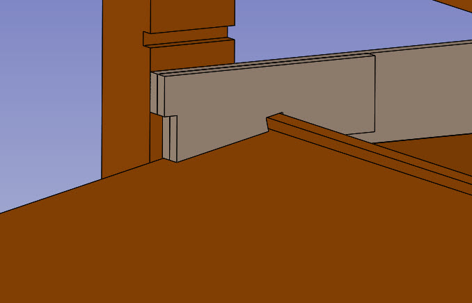
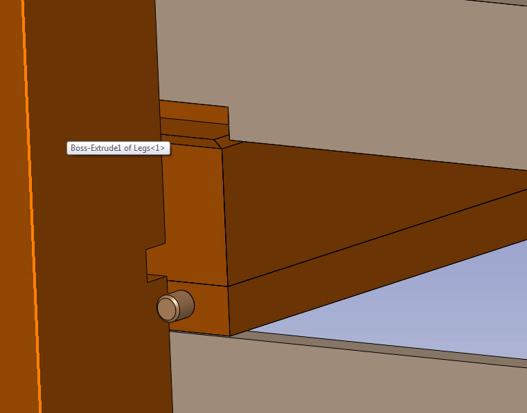
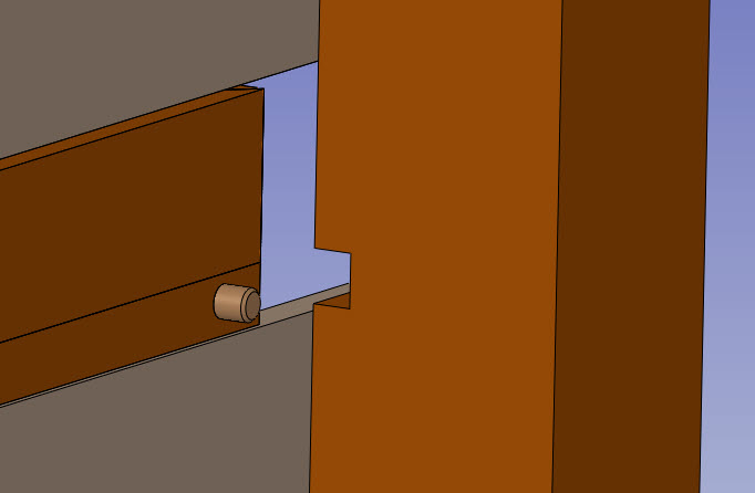
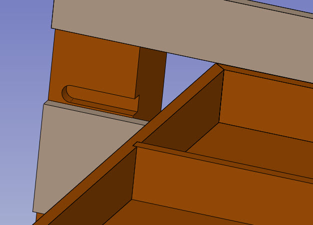
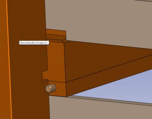
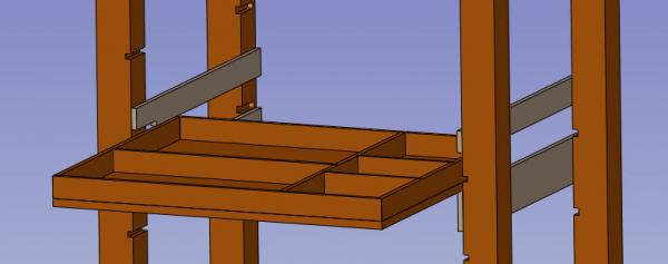
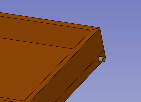
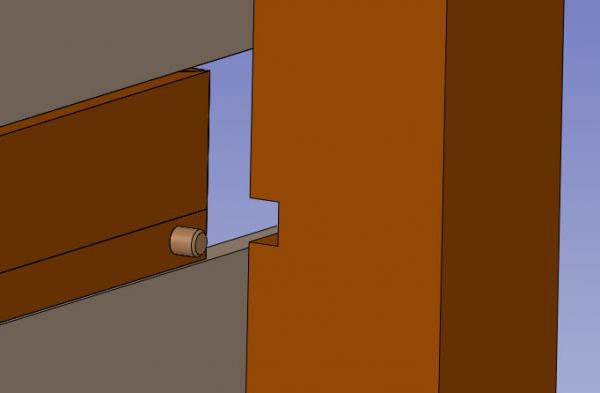
Then I cut fully through slots into the inner faces of the front legs but above the normal height of the dowel. And I gave the upper guide a cut out in the bottom edge. This means that when slid out the dowel contacts the rear of the front legs and stops it going any further. But you can lift the tray (into the cut out) a half inch which lines up the dowel and allows the tray to be removed. This is a view onto the back of a front leg to explain I will continue later Nick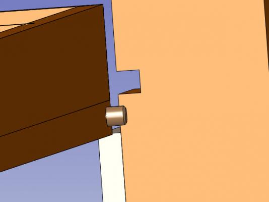
-
Design and Build a Custom Work Station
pompey2 replied to pompey2's topic in Modeling tools and Workshop Equipment
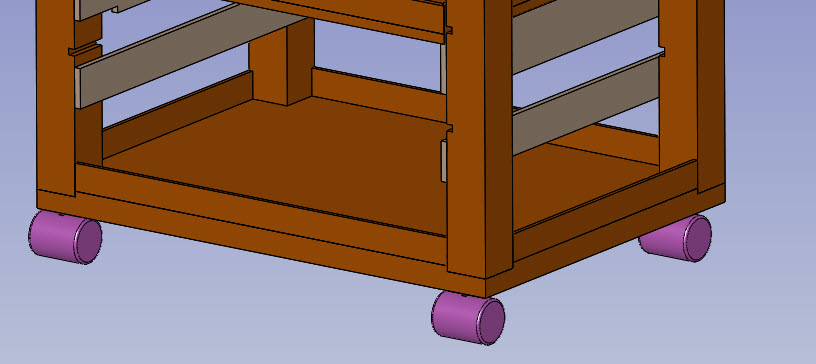
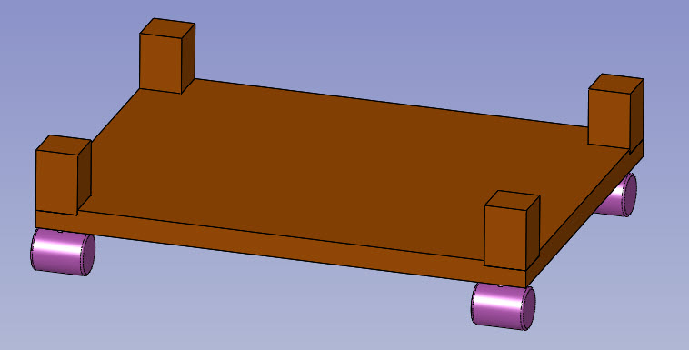
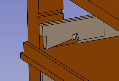
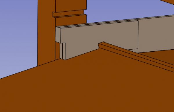
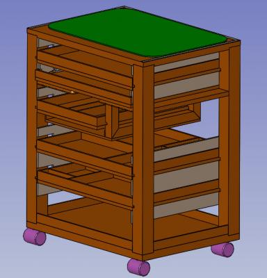
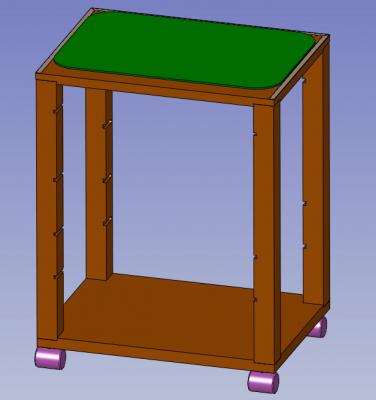
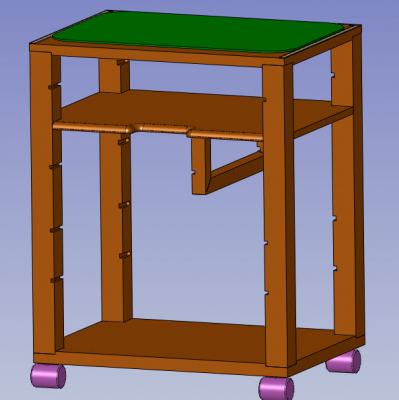
Next instalment Basic structure will be a base of MDF with low level castors and four timber legs let into the top surface I realised that I had to accomodate some higher items. But I didn't want to dedicate a full shelf/tray to them. So I am going to use a mid level fixed shelf and hang a smaller tray from that. That allows the lower tray extra height on part of its width. I also wanted to have a fixed shelf to store sandpaper sheets (mimimum height) So I added this to the fixed mid height shelf. The remainder of trays i want to be able to slide in and out to let me keep the height between trays to no more than their contents. I am going to have MDF strips each side above and below each tray. I have to stop the trays from pushing out the back or dropping out the front when used. So i started with a dowel into the each side at the back of the tray Then on the inside face of the back legs I cut a slot The slot is blind so it will stop the tray going beyond the back face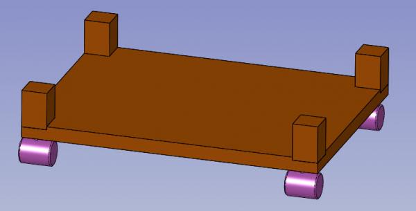

-
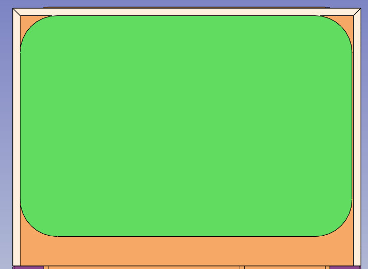
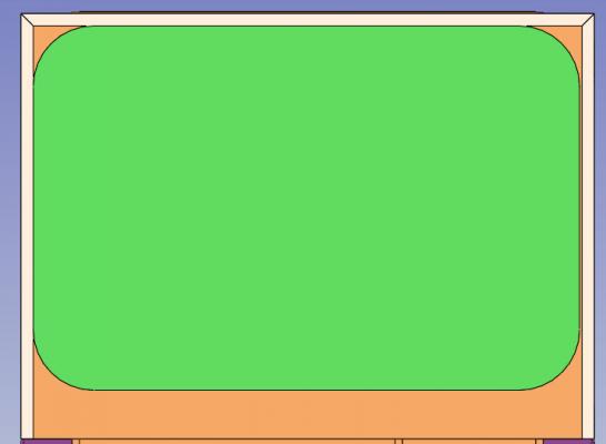
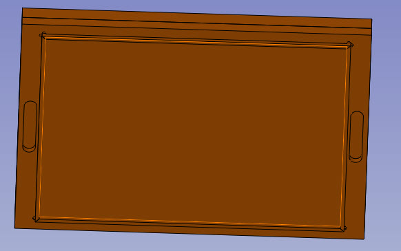
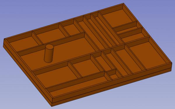
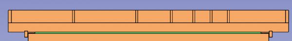
Hi I have been engaged on a project recently that I thought i might share. To Design and build a Custom work station. Problem: I am now at the stage of my Victory build (Rigging) where I need the ship at the front of my bench for access to get amongst the rigging. However I still need to use many tools and materails and use the bench for cutting, making bits etc. So I have a bench cluttered with tools and materails. A ship that has to come forward to work or be pushed back to allow space for a cutting mat and work room. Solution: Create a method of keeping tools etc close to hand, plus provide a secondary work surface. First hunt around for a suitable exiting option, result - find nothing even close. So I decide to make my own. As the thought process developed I realised there are many features I could incorporate which would be useful. Outline proposal: I am a SolidWorks user so I would do all of the desing in detail in SolidWorks, refine it and go from there. I want to have a tray, at a usable height next to my elbow, good size with well defined 'homes' for tools etc. To prevent it getting in the way it will need to be on castors. To prevent using up floor space it will need to push under my current bench top when not in use. It should also have facitiy to act as a work space with a cutting mat. It needs to be able to store all of my smaller tools etc which means I can dispence with my current tool box and various stogare devices. Should it be a 'pretty' piece of furnature? - absolutely not, to attempt that would compramise the functionality and be beyond my skills so function rules! Would this project be an effective solution, be a good use of time etc - absolutely not, but I will hugely enjoy the design and build process and that is reason enough - decision made. Materials to be mostly MDF and timber sections. Design underway: First consider the worksurface. Solution, set the size of the station to accomodate a cutting mat, include a thin surround to prevent the mat slipping around. Then plan a tray to sit on top of this surface, slightly bigger, with a four sided frame on the bottom face so that it will sit securely on top of the cutting mat - lift it off to use mat, otherwise at hand for contents. Include a couple of finger cutouts This is a view on the base I spent some time deciding which tools I wanted close and planned out the available space into compartments. Constuction to be 4 & 6mm wide timber sections x 25mm high. Cylinder represents the maximum height component And sitting in place: Thats it for the moment (out of time), i will continue soon. Nick
-
John, Glennard, Brian, Grant - Thanks very much for the generous comments. It's always nice having feedback. Nick
-
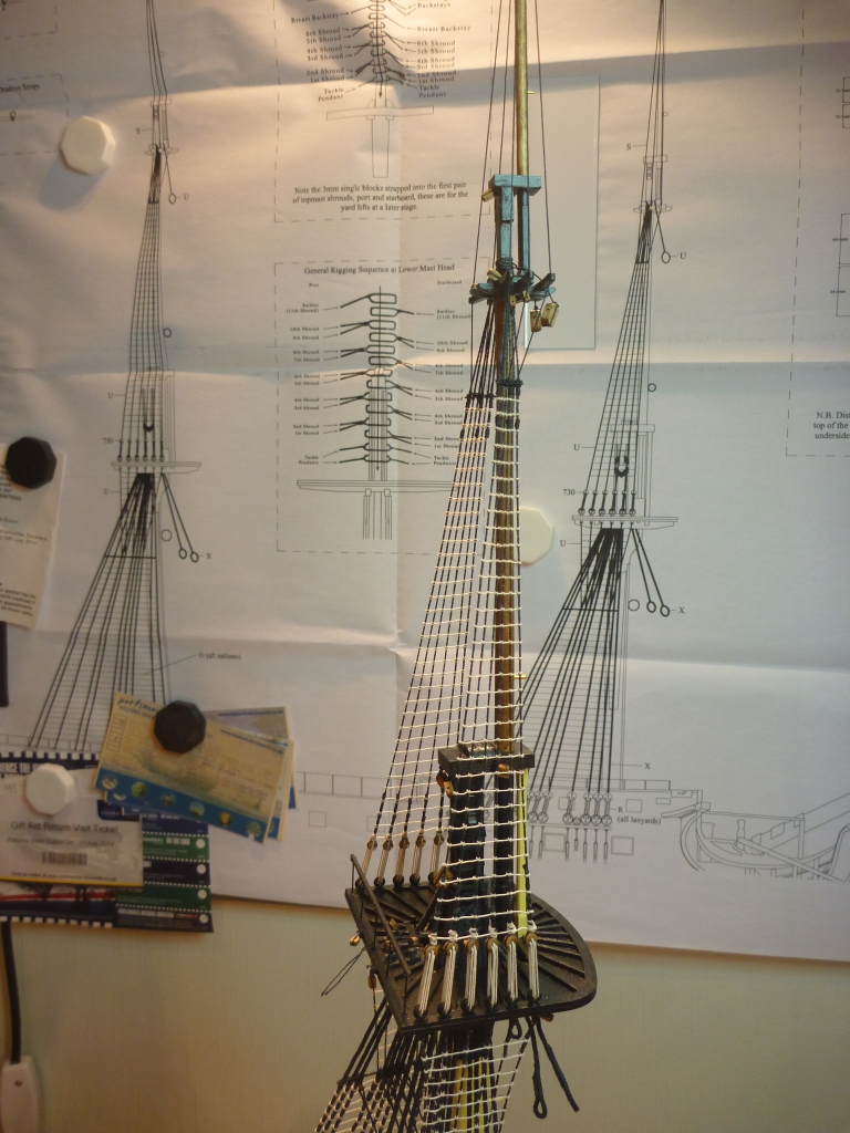
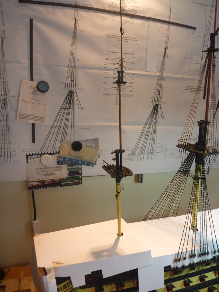
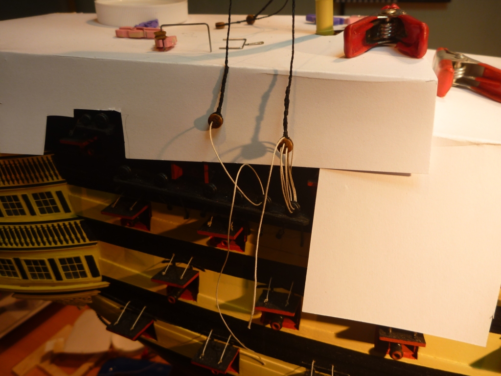
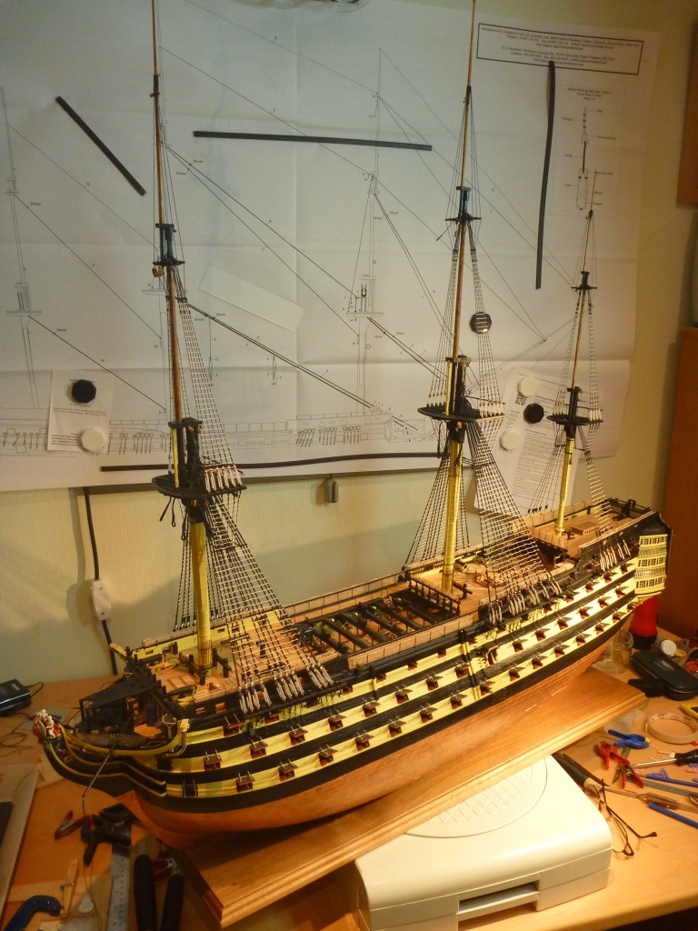
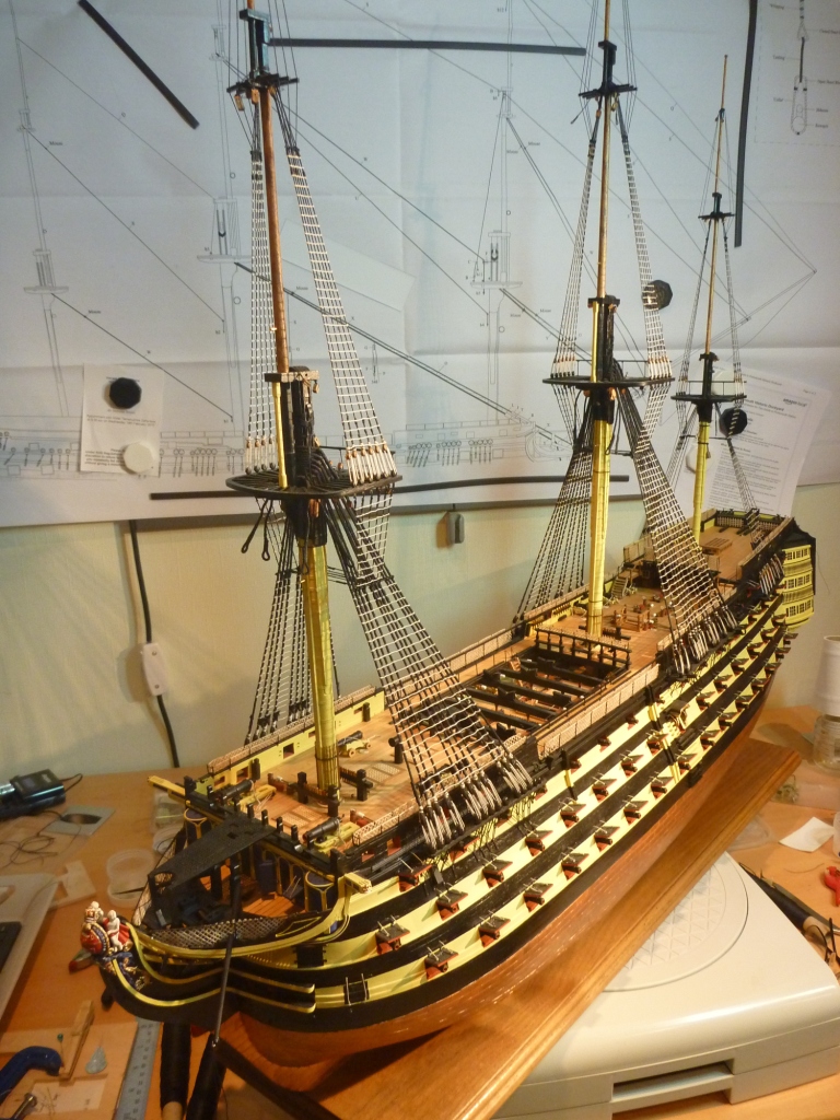
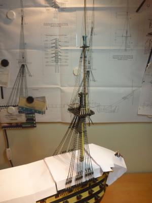
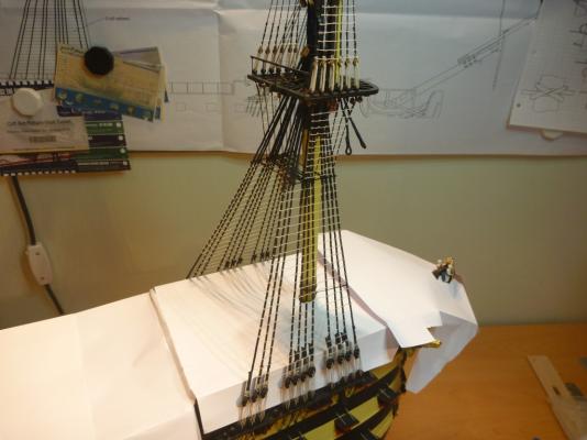
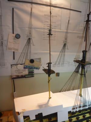
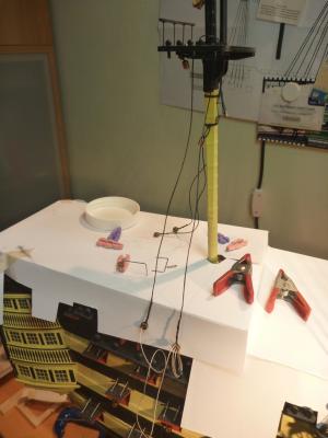
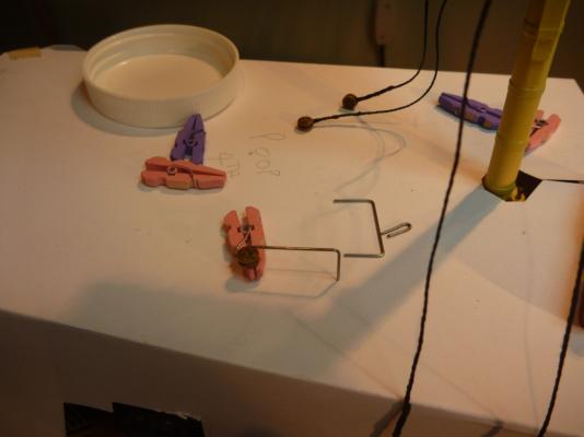
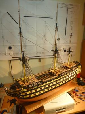
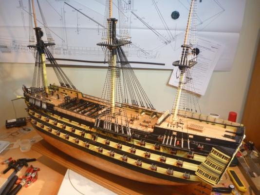
So, time for an update. Sorry it's been a while, rigging Shrouds and tying Ratlines has been keeping me busy now for months. Fore mast now rigged for shrouds, lower half Upper half And whole thing Mizzen mast next to do, Mast in place Starting to rig the first pair of shrouds Tying the Lanyards Using a little jig to get the dead eye spacing correct. Bit of a jump now. I didn't capture any more on the Mizzen. But have now finished all the Shrouds and Ratlines to all three main masts. Will leave the Sprit for a little while to give easier access. So here are a few shots of current stage. Now just starting to get onto the Stays. Nick


- 84 replies
-
- 6
-
-
- finished
- caldercraft
- (and 1 more)
-
Hi Rich I have only just stumbled across your build. Such a shame I didn't see it earlier. Just spent some time going right through. Your Vic is looking great and you seem to be making excelent progress. It's funny how many times i thought 'oh yeah i remember having a problem with that as well' Anyway best of luck with the rest of your tiles, looking good so far Nick (fellow pompeyite)
-
Hi Kevin, Victory is certainly looking top notch, great job. I always think the rigging is the more fun stuff and it looks like you will be there pretty soon. Enjoy Nick
- 1,319 replies
-
- 1
-
-
- caldercraft
- Victory
- (and 1 more)
-
Featermerchant - not sure of your shroud setup but traditionally Seamen would climb up the shrouds then on up the futtock shrouds around the outside of the top (crowsnest) which meant hanging upside down whilst climbing the futtock shrouds. This was a matter of some honour, you could choose to go through the hole in the top and not have to hang, but that is the Lubbers hole (as in land lubber) so was seen as for the faint hearted or newbies. Nick
-
Spot on Tim
-
Heading in the right direction
-
Ok, So here is one to be going on with. My first posted ship so could be a real easy one. Nick

-
Dziadeczek Sounds like a good idea for multiple parts, but a lot of work for 20/30? different spars/masts. Nick
-
Trust penknife always at the ready The mill has a small room out back with all of the history and a good collection of photo's an interesting extra visit for someone taking in HMS Victory Nick
-
It is the Watermill in Wickham, Hampshire UK. The name will provide the other evidence - the Chesapeake Mill Within its structure are beams from US frigate Chesapeake, captured in 1813 Taken out of servce and broken in Portsmouth a half dozen miles away. Many of the timbers were bought by the miller. It's now a very quaint Antique market which I visit every now and then Not sure I will get another clue posted so please feel free to take my turn.
-
Making sails for HMS Victory
pompey2 replied to rafterrat_2005's topic in Masting, rigging and sails
That's an interseting thought. You would need to think about wind direction carefully. It's rarely from directly astern and the finished model would need to reflect a common direction. Nick -
The Unimat has quite limited between centres (135mm) and centre height (25mm) unless you start adding on extras. If you do that the cost then makes it seem less of a reasonable option IMHO
-
Hi Ian I use a scheppach DMT450 benchtop lathe. It costs about £280 It has a 1/2" through hole on the headstock which is important if turning long yads etc. And a between centres of 445mm. I added a 3 jaw chuck which helps a lot and I built a 3 roller fixed steady from MDF for it. I have found it very good for spars and masts. I have turned all of my Victory ones even down to 2mm dia. Of course at that diameter it is sandpaper rather than a chisel. The steady is required if you go to that sort of dia. http://www.amazon.co.uk/SCHEPPACH-DMT450-445mm-Woodturning-Lathe/dp/B00FBD2MMU/ref=sr_1_6?s=diy&ie=UTF8&qid=1407761322&sr=1-6&keywords=scheppach+lathe Nick
-
Making sails for HMS Victory
pompey2 replied to rafterrat_2005's topic in Masting, rigging and sails
I think you will find a reasonable set of sail plans in Alan McGowan's 'HMS Victory: her construction, career and restoration' I'm not at home to check for sure but if memory serves they are pretty thorough. Nick -
3D Printing - Not Just Yet!
pompey2 replied to dvm27's topic in CAD and 3D Modelling/Drafting Plans with Software
We do a quite a lot of very fine metal parts for myday job. Selelective Laser Sintering SLS- can be done with range of metals, titanium, stainless steel etc. Finishes are getting better and better. You would be hard pressed to see the grain sturcture in some Of course cost remains the issue Nick