


bcochran
-
Posts
598 -
Joined
-
Last visited
Content Type
Profiles
Forums
Gallery
Events
Posts posted by bcochran
-
-
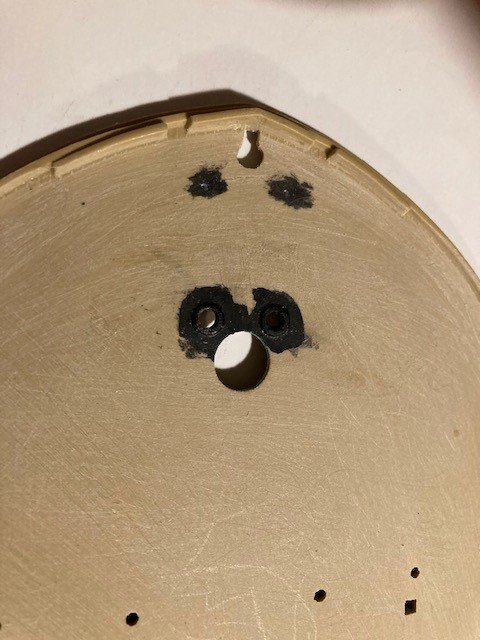
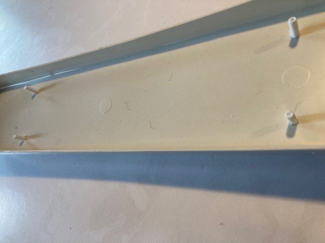
I have the main deck sanded and ready for the edges to be painted. I cut out the place where the jack staff goes. I will have to duplicate that and the capstan hole on the wood deck once it is glued down. Then I will put a bit of sheet plastic under the holes so that they are just depressions, note holes.
I painted the holes for the anchor chain and the place where I filled the Pyro ring hole and drilled it out for an eyelet to be added once the wood deck is down. These force me to glue the wood deck to the plastic deck before I glue the deck to the hull.
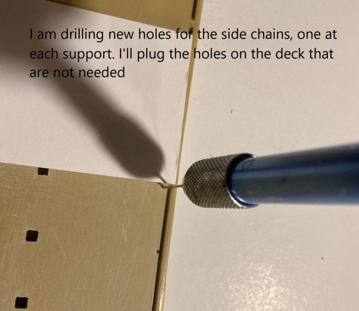
I filled the Pyro holes for the side chains, then marked and drilled the holes for the side chains I want to add.
Next I need to paint the edges of the deck white and add the chin holes and capstan and jack staff holes in the wood deck.
.jpg.956478823061bbe303d4c640406f7b3f.jpg)
-
16 hours ago, shipman said:
No keeping a good fella down is there?
Whatever floats your boat with this one, I admire your tenacity.
It's so easy to get absorbed in what you're doing and in a moments lack of concentration something finishes up on the floor and without thinking you bend to pick it up. In your condition that could do more than ruin your day.
Hope you aren't alone. Please take care.
I'll sit back and see this one through.
Hi Shipman,
Glad to see you here. I don't live alone. I have a wife and 4 dogs. The funny thing is that I can't do my chores like I use to. She has to do everything. It's not funny, and I love her for caring for me.
-
Hello John,
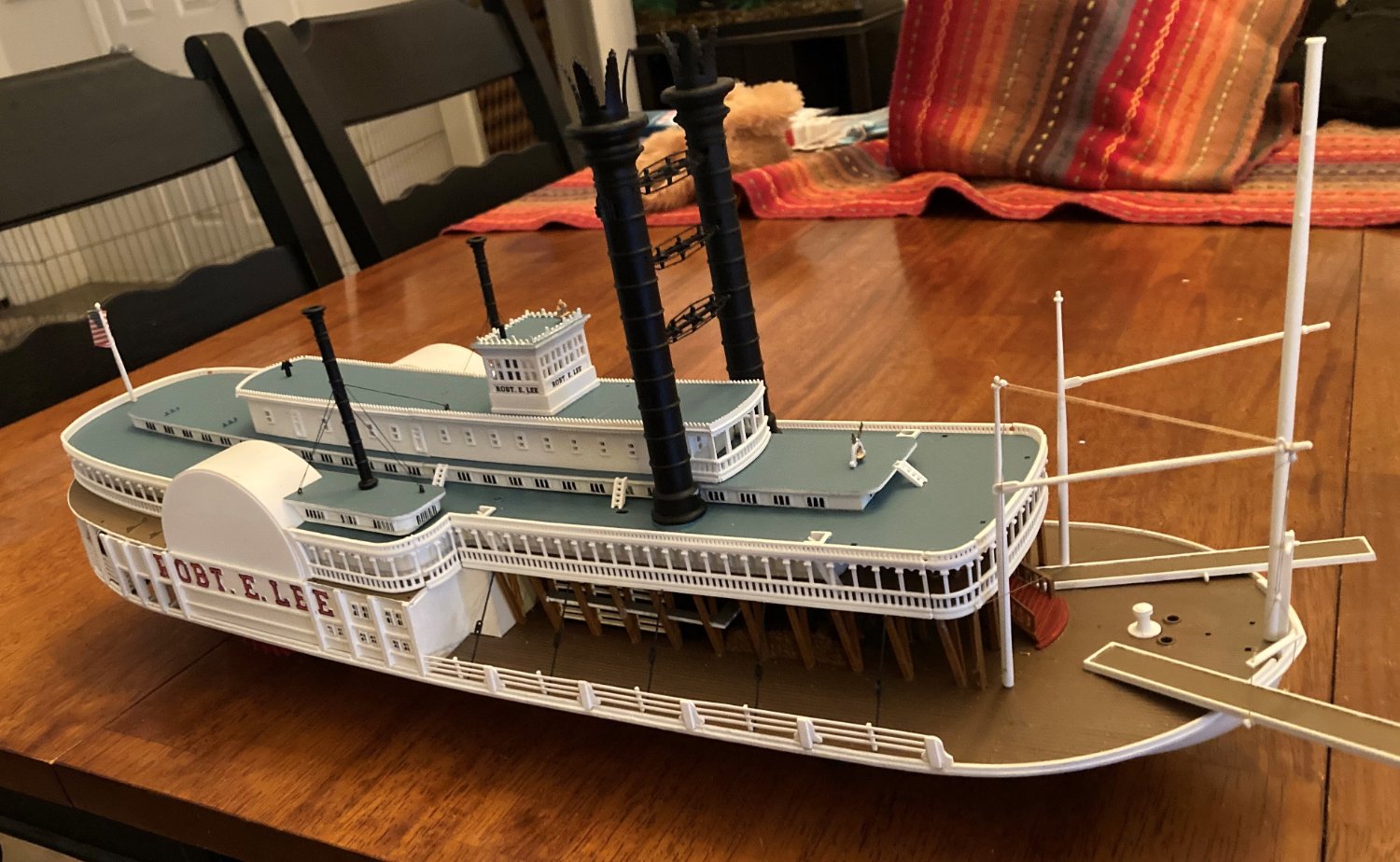
I really like your work and all the effort you are putting into your model. I started a build log for a Pyro plastic 1/163 Robert E Lee.
The plastic model does not have quite the detail you are adding to your model and of course it is plastic not wood. I could never see myself building a wood model of the Lee.
But I am sure I can learn a thing or two about modeling the boat from your log.
Keep up the good work.
- mbp521, Glen McGuire, Ryland Craze and 2 others
-
 4
4
-
 1
1
-
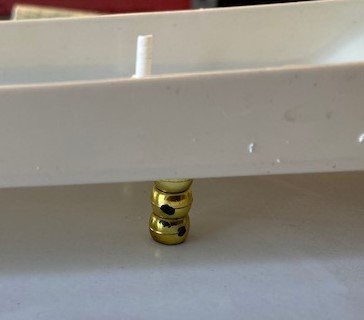
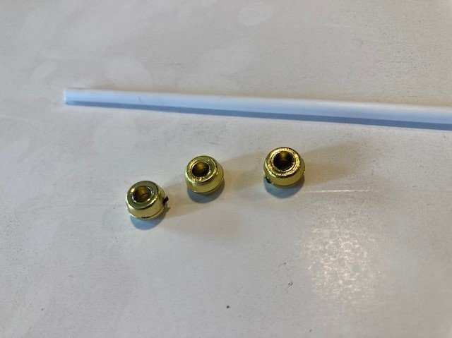
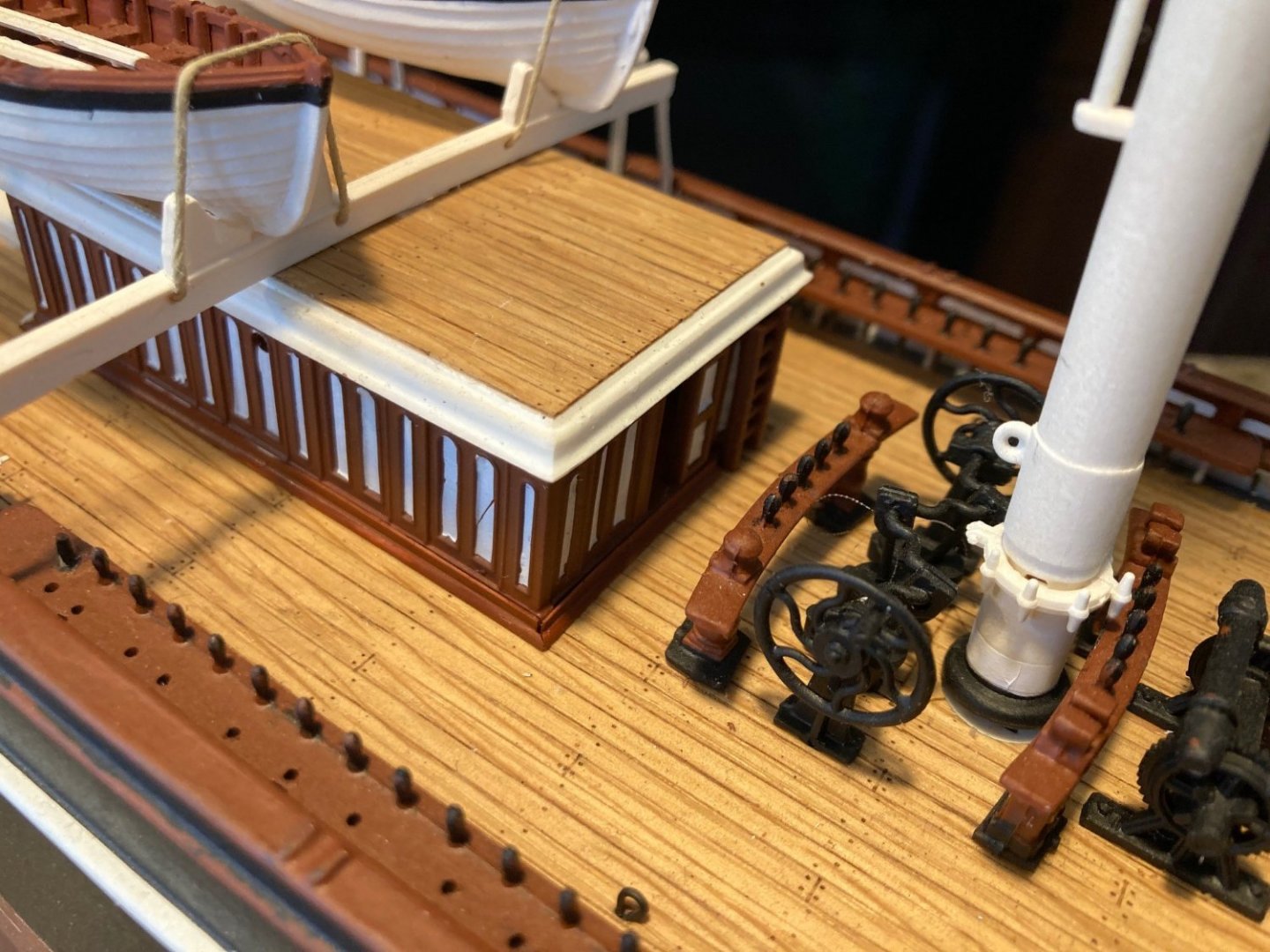
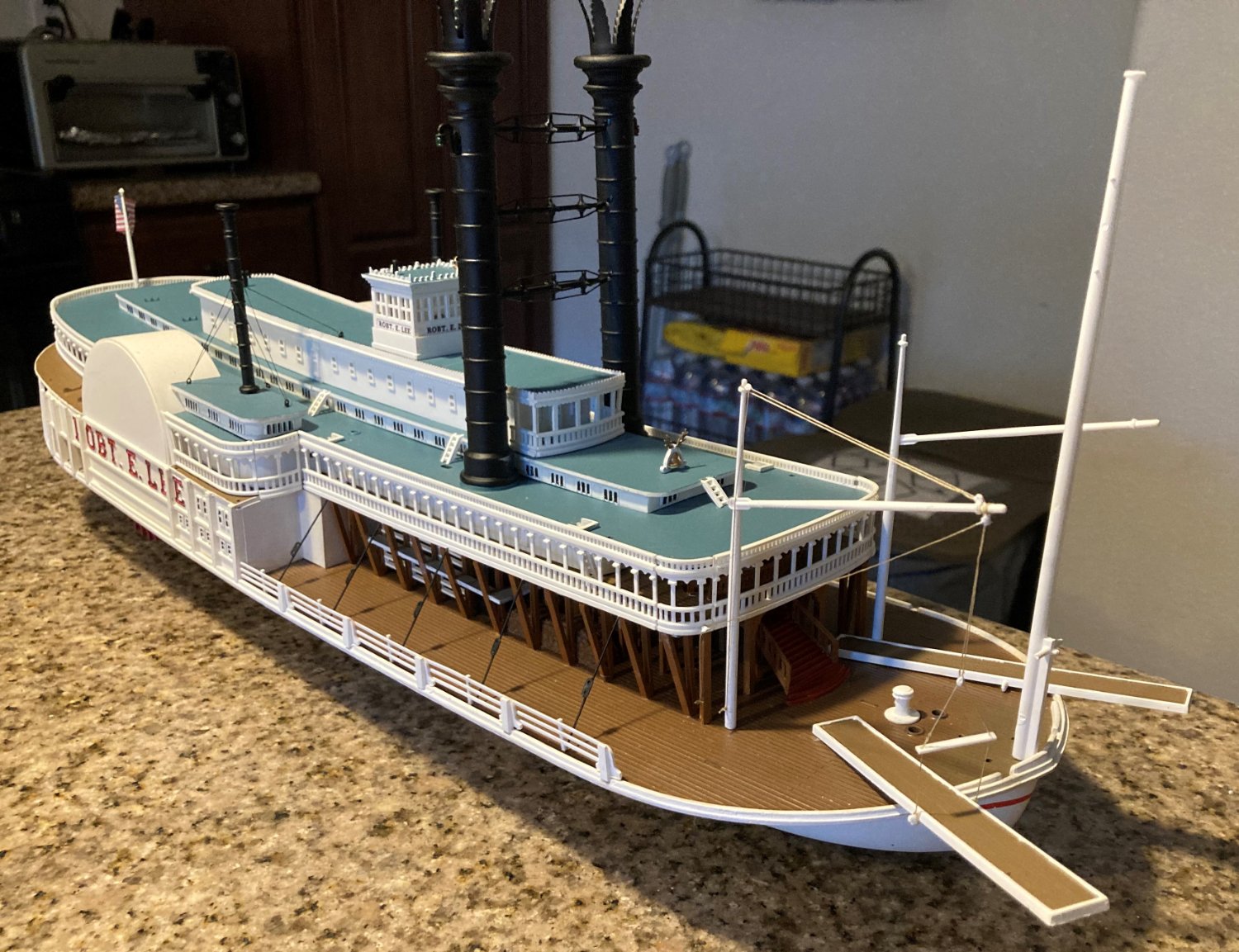
I needed some kind of display stand. I felt the kit supplied stand was too big for the size of the model. It looked too out of place. I designed something simple but a little more elegant.
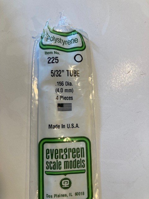
I marked off four holes in the hull for the parts. They are an inch off center. 9 1/2 inches apart and about 5 1/2 from the ends of the hull. The pieces are plastic tubing and three plastic beads.
I drilled holes in the hull to fit the tubing. They are mounted temporally now, but once the hull is painted they can be mounted permanently.
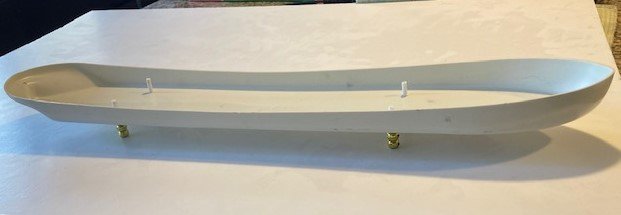
The reason for the four pedestal pieces is that I have a display case with a wood base, and I did not want to mount the model to the display case's base and to keep the model the right height for the display case I didn't want to mount it to another piece of wood. I just sit the model in the display case.
It also makes a stable platform to build the boat on.


- Ryland Craze, coxswain, GrandpaPhil and 4 others
-
7
-
No replies yet, but here goes.
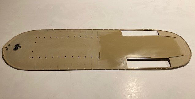
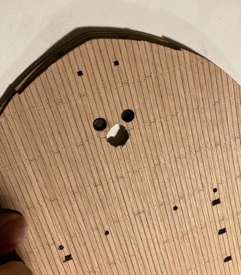
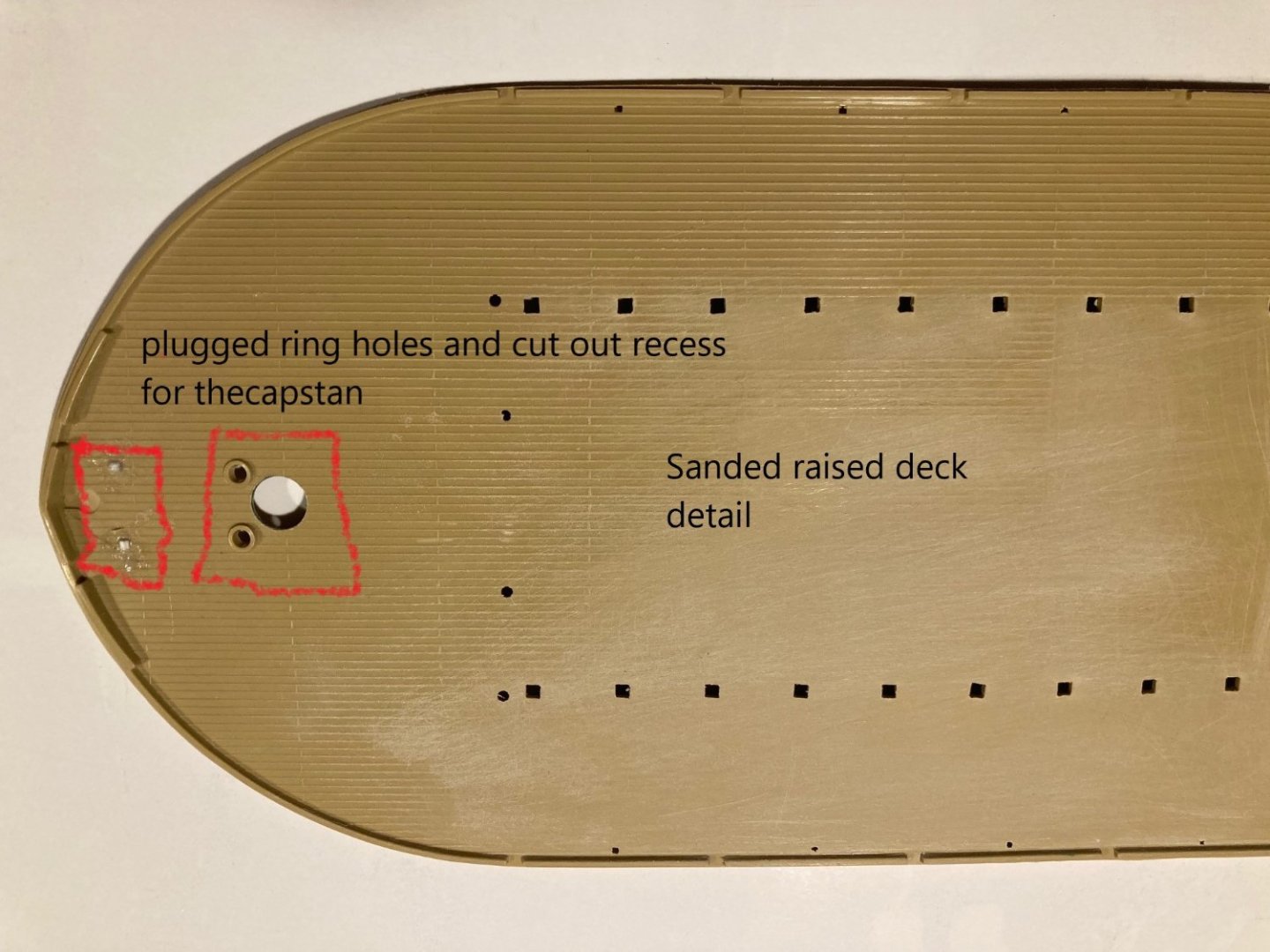
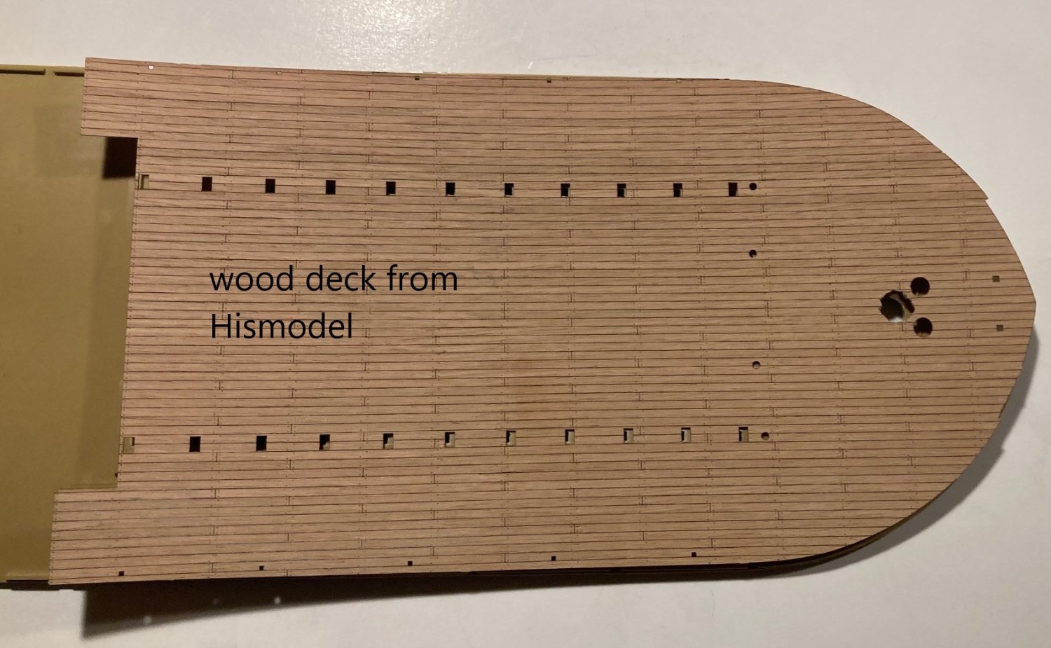
I am going to apply a wood deck sold by Hismodel. In order to do that and to add some detail, I need to prepare the plastic deck.
First, I need to sand off all the raised deck markings. I have used these wood decks before, and learned that liquid plastic model cement is good for gluing the wood to plastic. Also, I need to make the depression for the capstan in the wood deck and for the jack staff. To do the hole for the capstan, I cut out the depression in the plastic deck and using that hole to mark the place for the opening in the wood deck. I then roughly cut the hole in the wood deck. I will wait until the deck is glued to sand the hole smooth, then using a piece of styrene sheet under the plastic deck to put back the bottom of the depression. I will do something similar to the jack staff depression.
The holes in the deck and the side have a lot of flash to file and sand off.
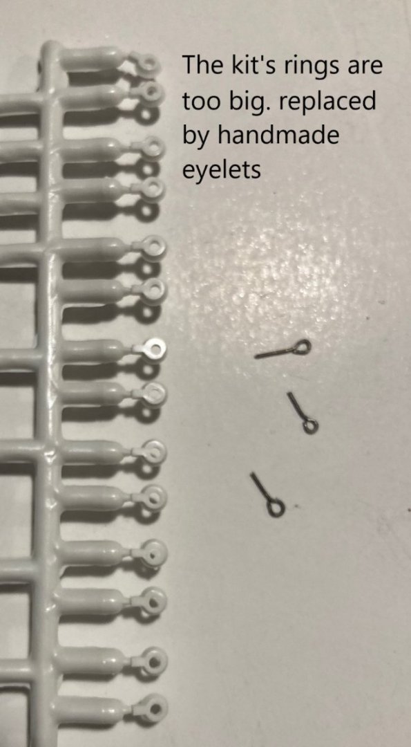
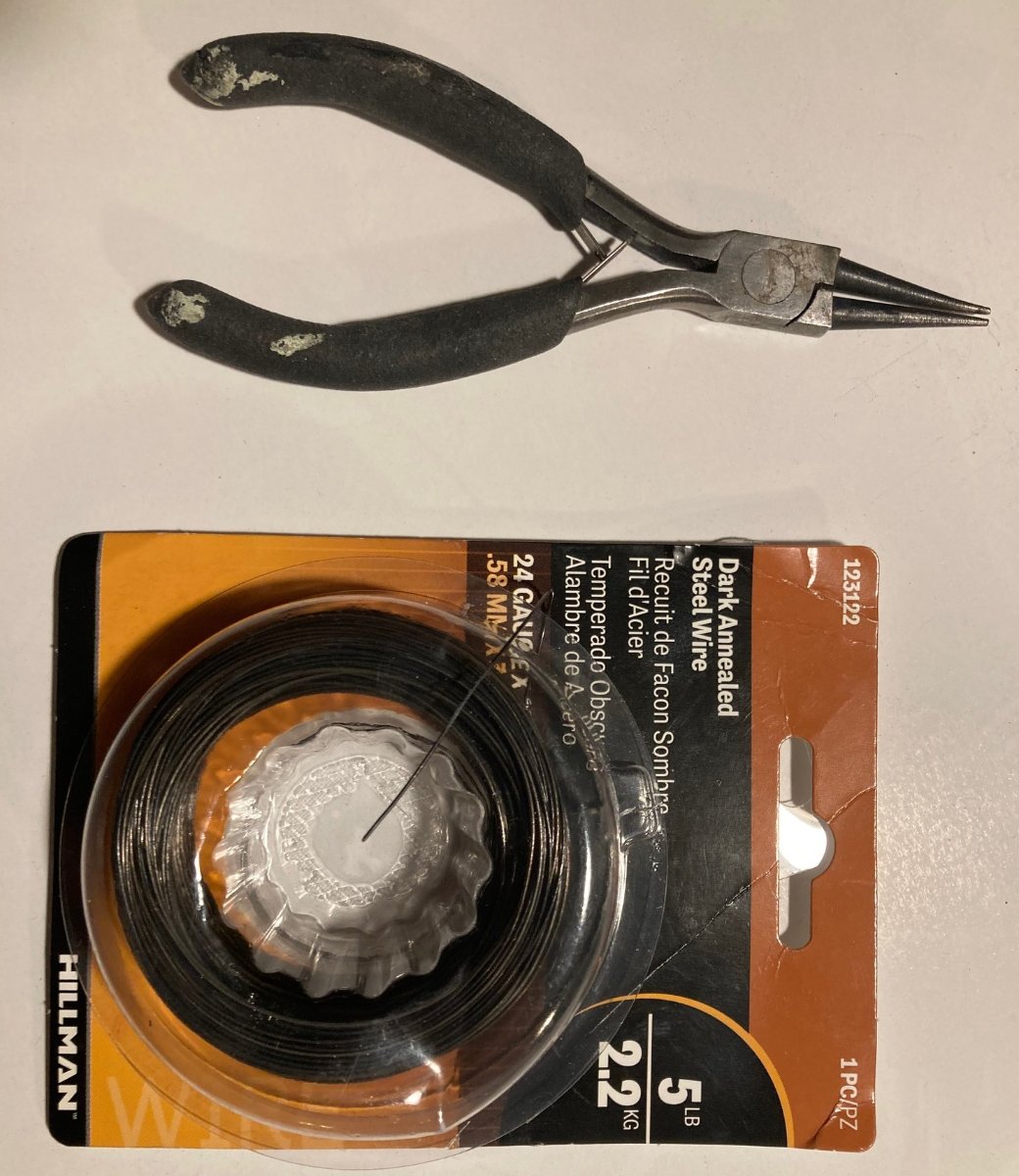
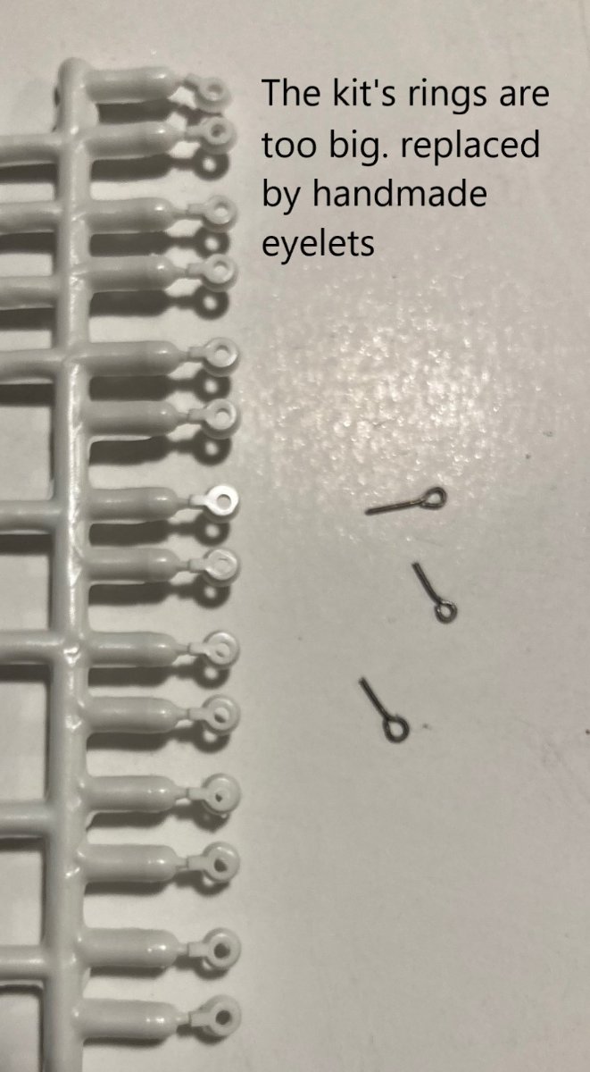
I plugged the holes meant for the model's rings. They are too big in my opinion and not needed in some places. I will substitute eyelets I make from 24 gauge dark annealed steel wire.
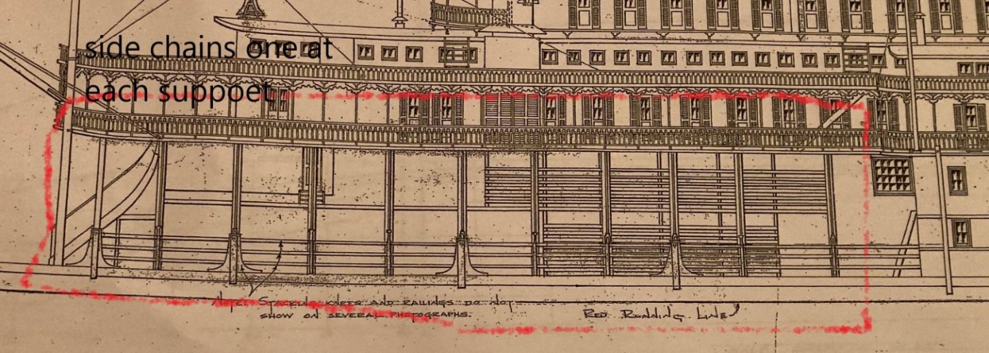
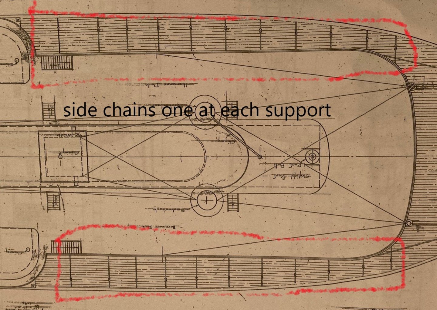
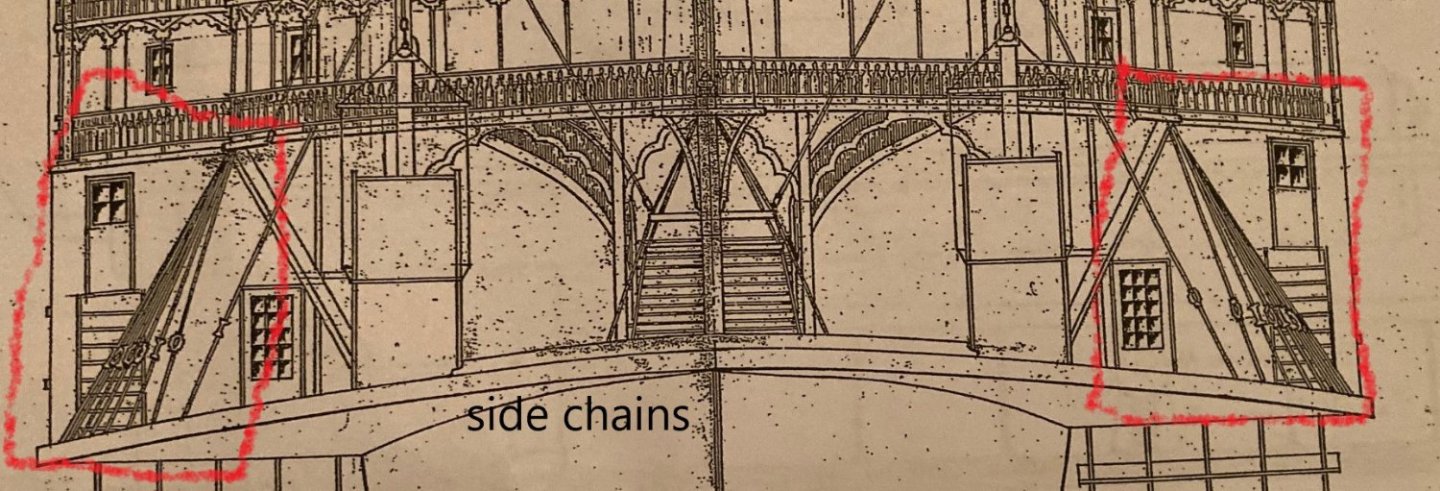
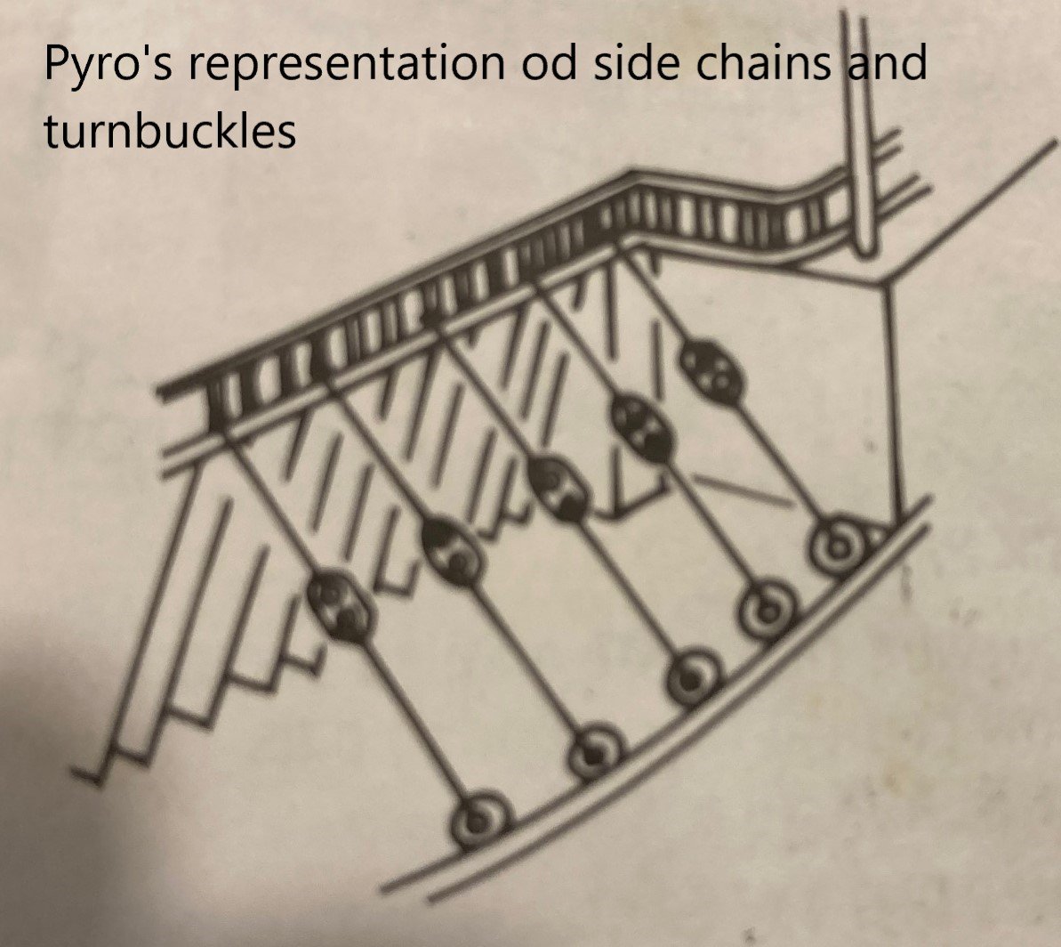
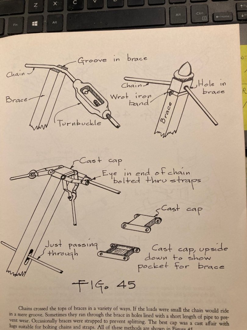
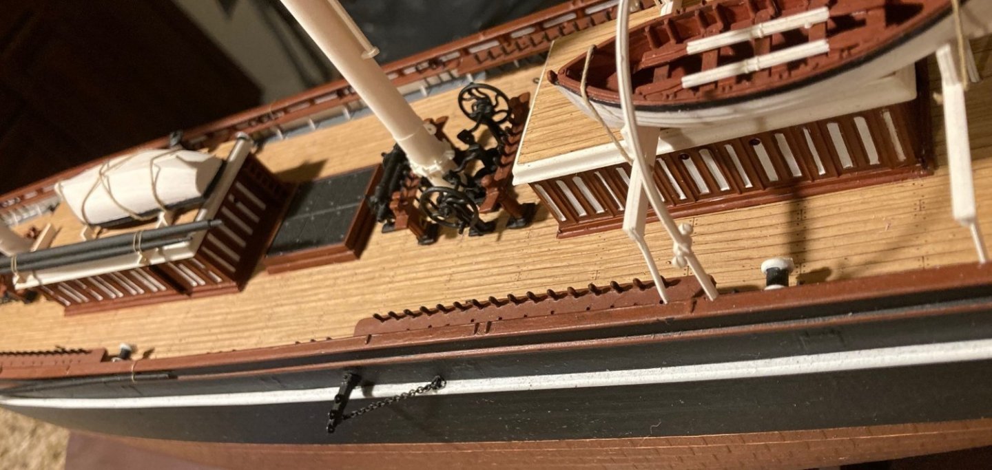
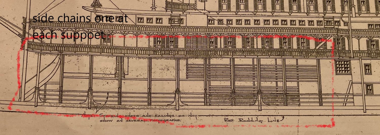
The model's instructions show some lines going from the deck to the side of the boat at the boiler deck level, with something that is supposed to represent a turnbuckle. (The decks on the boat from bottom up are the main deck, the boiler deck, the hurricane deck, the texas and the pilot house.) These lines are really the side cross chains. Since the hull and deck are so thin, without support the deck would "hog" meaning the sides would droop down. To prevent this, cross chains were added. They are attached to one side of the deck, across the "V" supports down to the other side of the deck. They act like the hog chains that go from the bow to the stern.
The model has places for 5 of these cross chains. The real boat has one for each of the "V" shaped supports, and I am going to add this detail. I will use wire and plastic turnbuckles that are model railroad detail parts. They are made by Grant Line.
See my pictures for more information.

.thumb.jpg.244a088d3342fe21688eff2be1f097aa.jpg)

.thumb.jpg.d0446b4451a9d6f71e96841c80b0b7a6.jpg)
- Ryland Craze, Knocklouder, CDW and 5 others
-
8
-
Hello folks,
I already have a build log of my Revell Cutty Sark. Last week I had major surgery on my spine. I am not supposed to bend, lift or twist for a long time. I felt that working on the rigging of my Cutty Sark would involve those movements inadvertently. The rigging is what I need to do to finish the model. I will finish that model, I've come too far on it.
So I started on this Robert E Lee steam boat Pyro model. With this I just sit at my table and work with my hands and not much movement.
My kit is Pyro | No. 237-795 | 1:163 My kit is complete and was issued in 1961.
I have a full set of plans that are described at the Online Steamboat Museum as :
This is a set of huge drawings of the Robert E. Lee. Nine plates or pages (blueprints) each page 48"x17.5" and completed in 1977. They were used, I believe, by a world-class model builder and supplier of parts from Royal Oak, MI. to either cast parts for the model or it was one in his collection. Rare history of the robert e. lee is included. I've had contact with the illustrator and he admits he never signed his earlier drawings which makes this quite valuable I would believe.
I also have "The Western Rivers Steamboat Cyclopedium" by Alan L Bates along with other reading on steamboats and the Robt E Lee itself.
I have seen other discussions of this model and the Robert E. Lee itself on other sites. A lot of the information there I feel is conjecture. Seems not many people know much about steamboats.
I have been reading about the boat. That is where I get my opinion about the conjecture. I will try to document the reasons for the detail I am adding using my reference material, so that my information is not conjecture. I am trying to make an accurate model but as stated elsewhere, Pyro's model is probably not 100% accurate and I won't change it much.
Pyro's model was reissued by Lindberg. I have built this model before. I learned new things that I didn't know then.
Pyro's model does not match the plans much at all. Like My Cutty Sark I do not intend to rework the model in any way. I do add details where I think they could enhance the model.
The plans and the Cyclopedium have general information that is useful in building any steamboat model.
So let me know if you are interested in another build log of this model.
This drawing is similar to the Pyro model.
.thumb.jpg.0b73a22988865a95580d2381360b1652.jpg)
-
I am most likely going to disappoint some people, but I have to put my Cutty Sark on hold.
The reason is that I had major spinal surgery. I was in the hospital for four days and am home now recovering.
To continue to rig my ship while I recover isn't possible because it would involve movements that I am not permitted to do, such as bending and twisting.
.
In the meantime, I will be building Pyro's Robt. E. Lee steamboat. It is just like the one I pictured here. That one was in process over 10 years ago. I stopped because I could not paint the lettering on the paddle wheelhouses. Practicing on the model I pictured her, I developed a method to do it.
So for the time I am healing, I will build the steamboat. If anyone would like to follow along with me, I could start a build log
I have a complete set of the old plans for this boat, but I can't follow exactly. Those plans are for a different boat. There were three Robt. E. Lees built. The first was broken up to build the second one using parts from the first. I have a hunch those plans are of the second Lee. Ir is much fancier than this model. But some parts are similar. There is a build log online using those plans. That boat is scratch built and is in 1/48 scale.
I have those detailed plans along with "The Western Rivers Steamboat Cyclopedium" by Alan L. Baits.
So if I start a build log on the steamboat, people can glean some ideas and learn from my reference material which I can photograph.
I have seen other build logs of this plastic steamboat model, and I think the builder did not have much research material.
So if anyone wants a build log of my steam boat, let me know.
I promise, I am not giving up on the Cutty Sark. I have only the rigging to complete, and I want to complete it.
-
I hope to come home from the hospital today. I have been here 4 days. It is painful to walk or move. I will be back working on my ship but I don’t when yet.
-
-
-
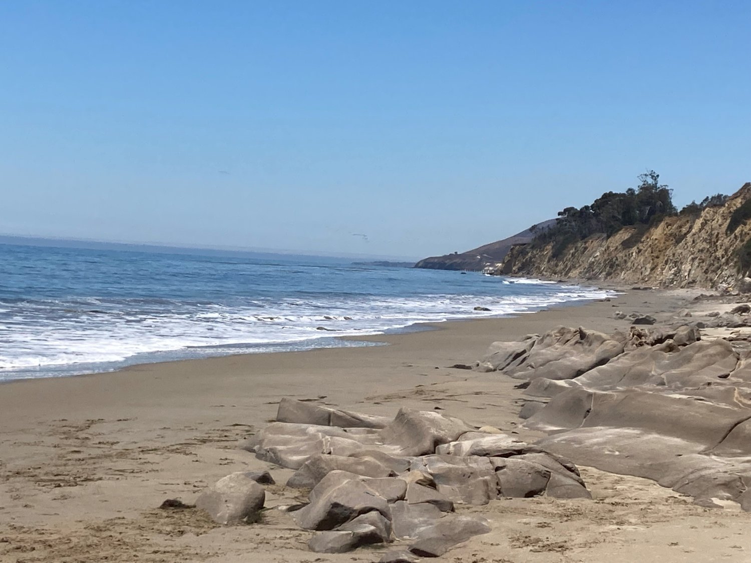
I usually don't work on models over the weekend in the summer. My wife and dog and I spend summers here at the beach whenever the weather and tides are right. It is just a short drive from our house. I could never live inland. I love the sea and not being land locked. We will be there tomorrow. Low tide is at 12:05 PM and air temp is 80F.

-
-
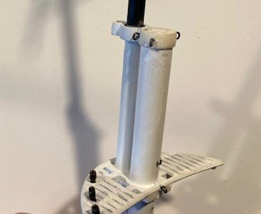
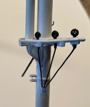
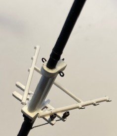
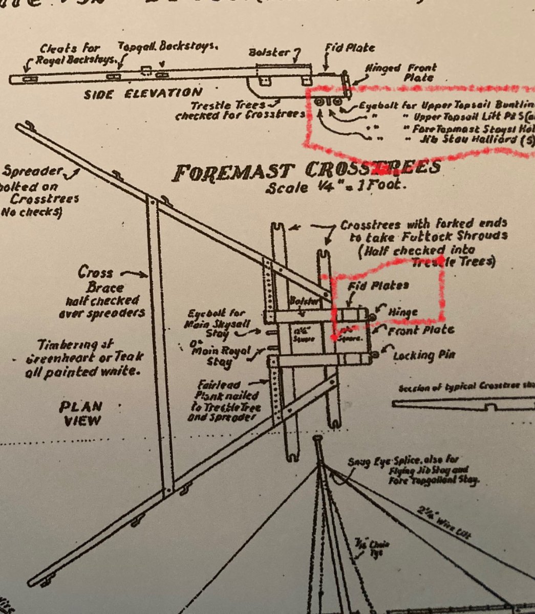
13 hours ago, Ian_Grant said:
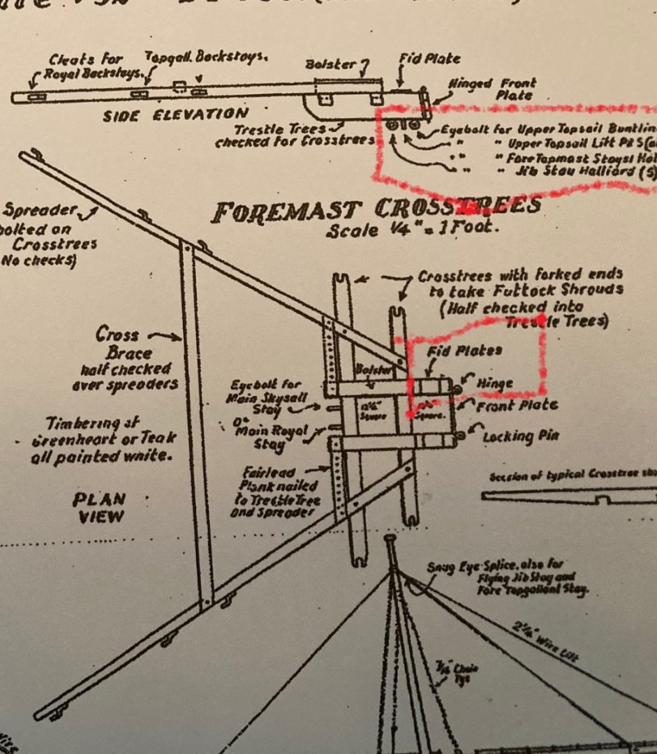
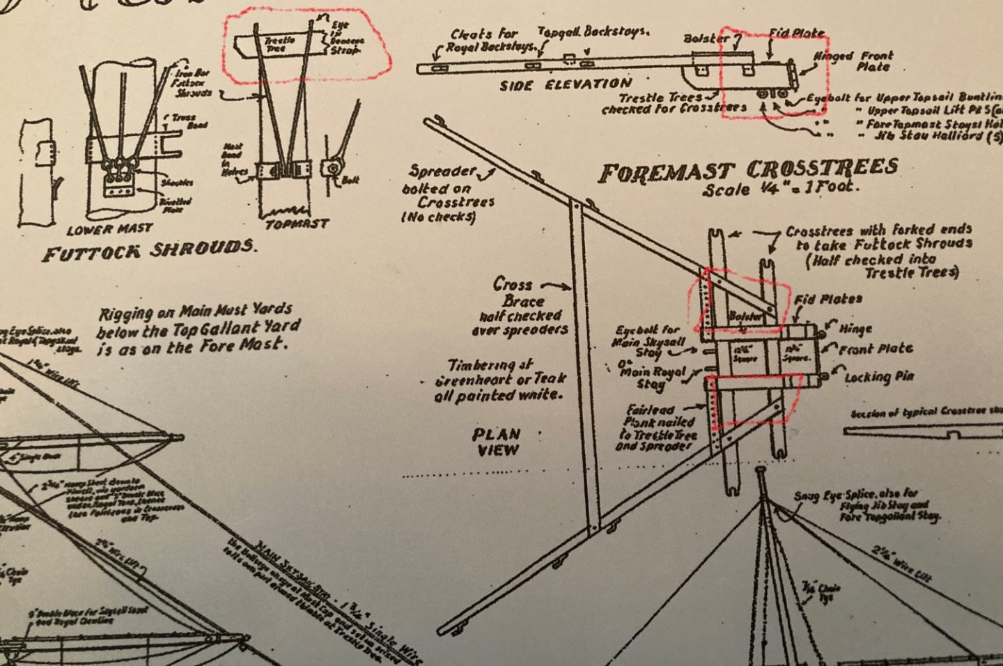
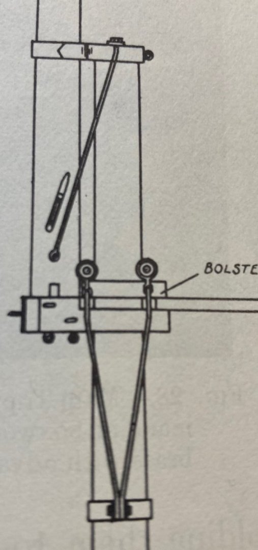
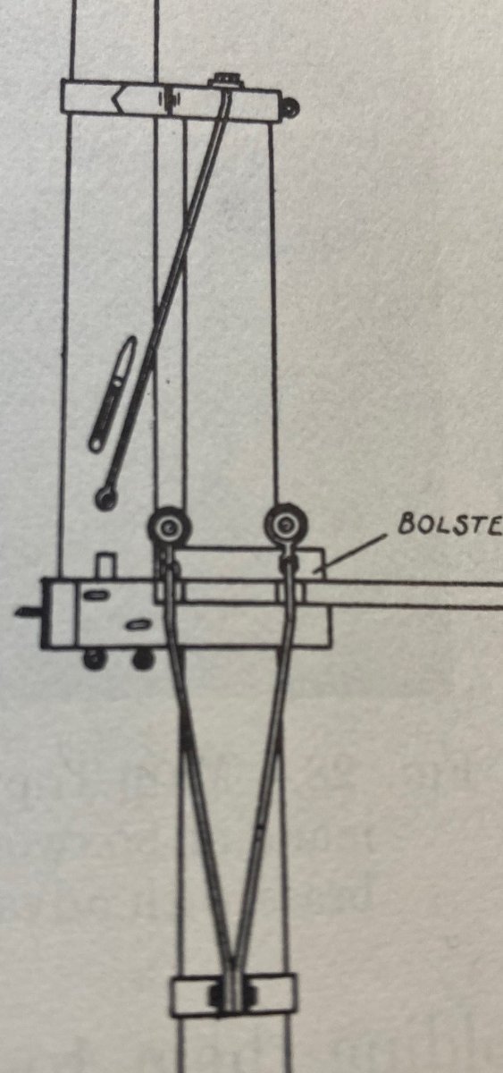
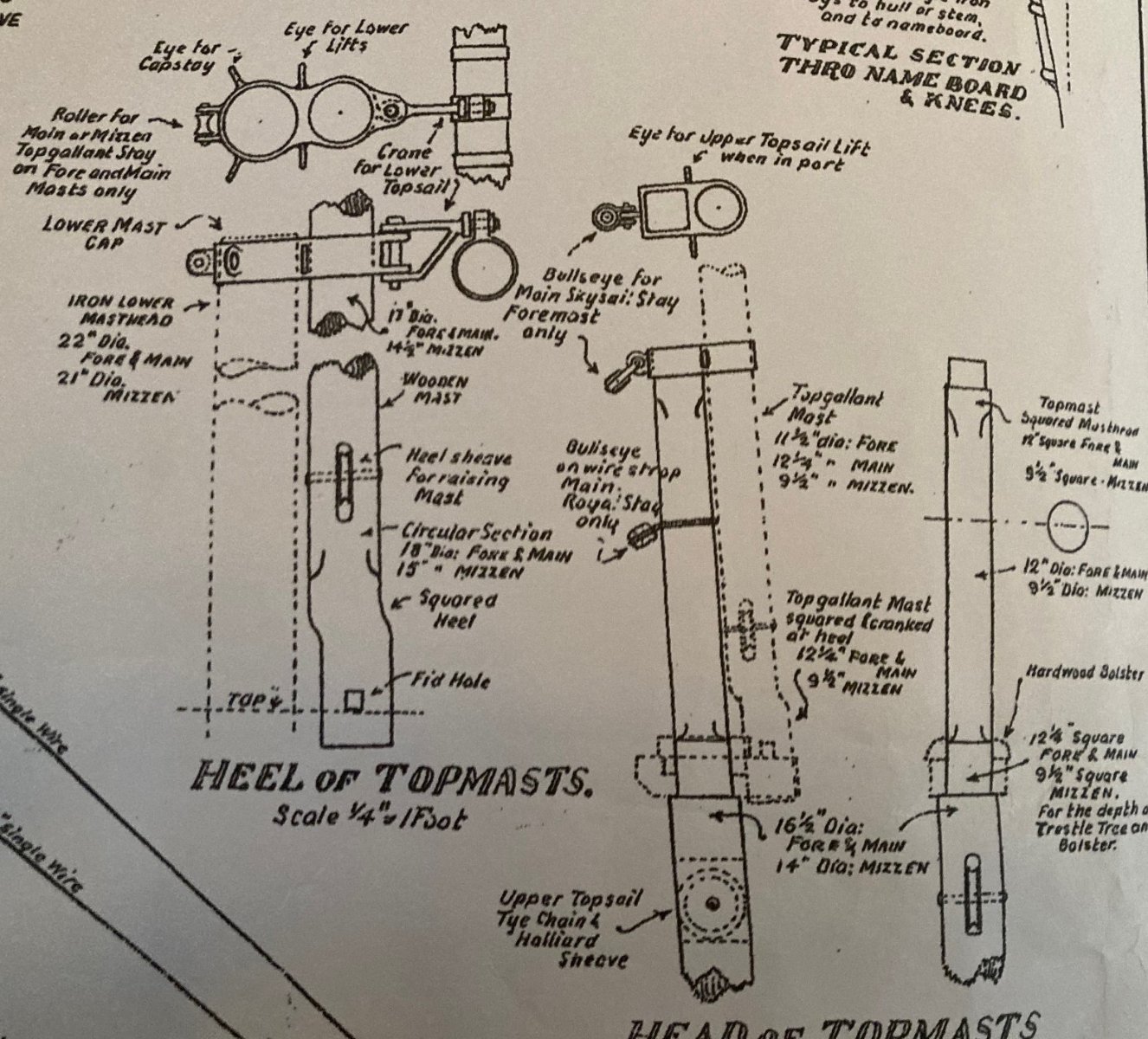
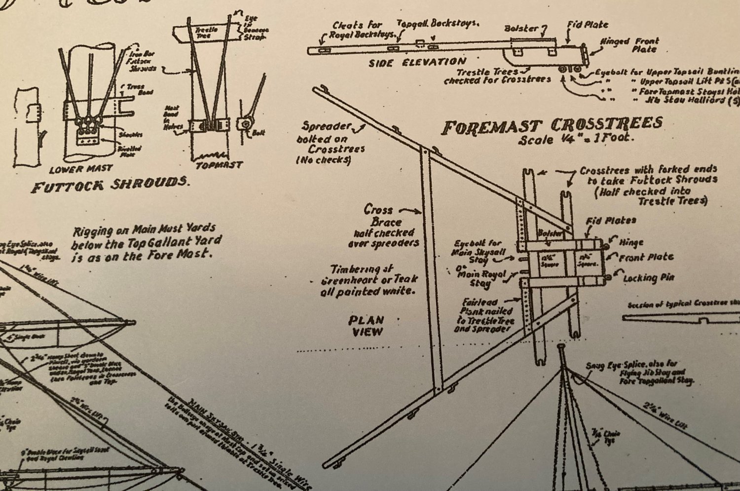
Underhill mentions that the upper topsail lifts are seized to shackles at each end of the topgallant mast fid (!?), and the upper topsail buntlines pass through a double block seized beneath the cross trees.
Bottom line is there are more ways to rig stuff than there are ways to skin a cat. For my Preussen I just look through Underhill, rig it in a reasonable way, and about 0.01% of people would even know what they're looking at. 😄
Campbell agrees with that.
-
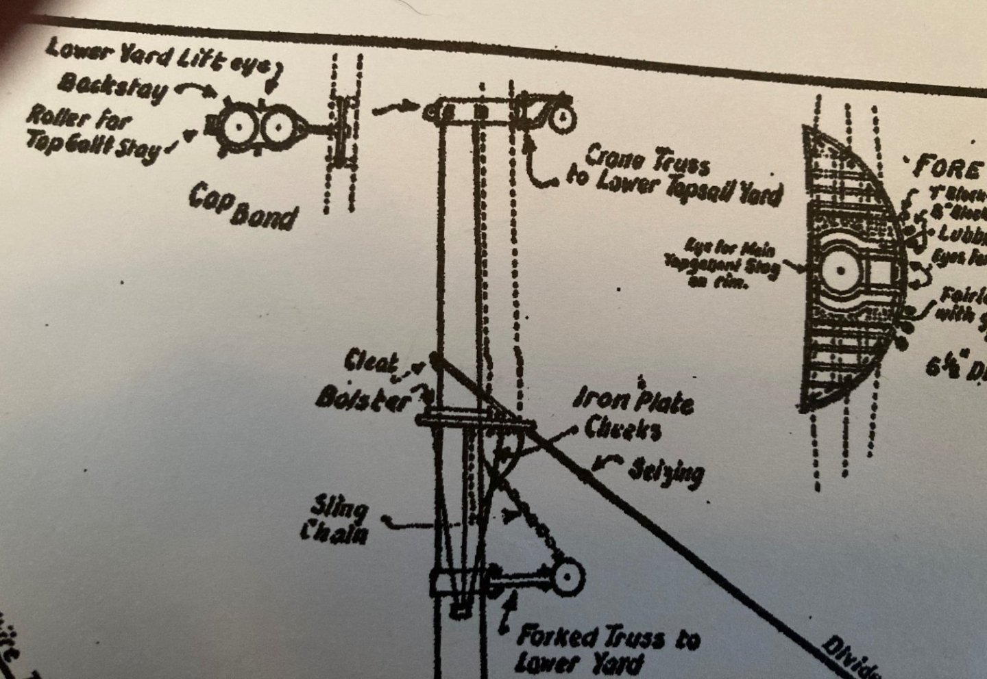
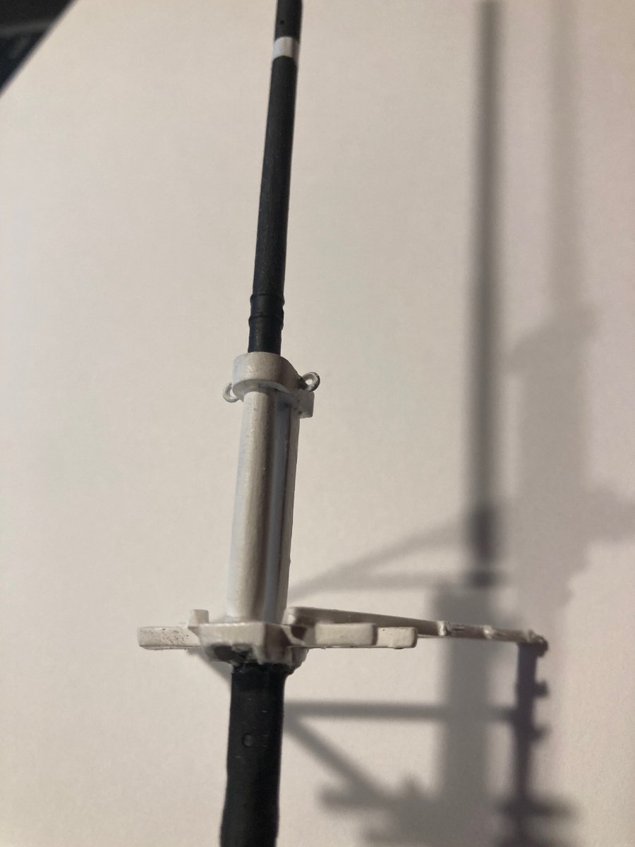
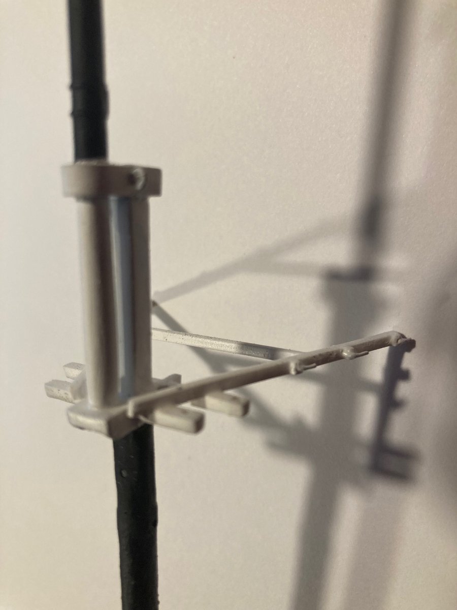
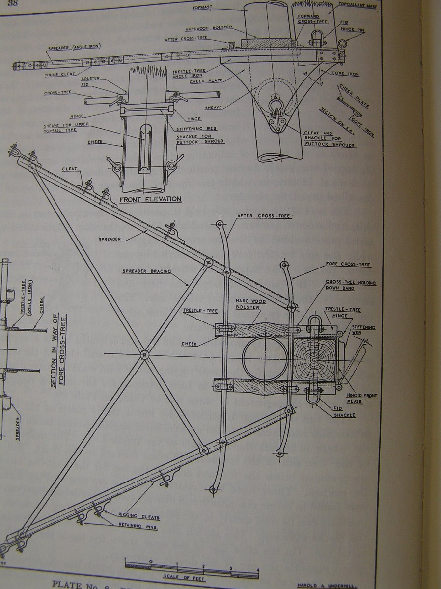
34 minutes ago, Ian_Grant said:
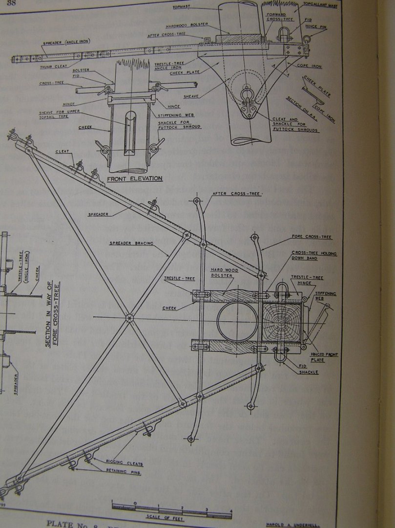
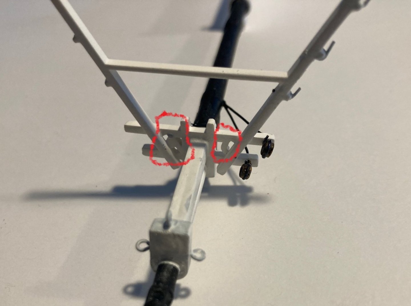
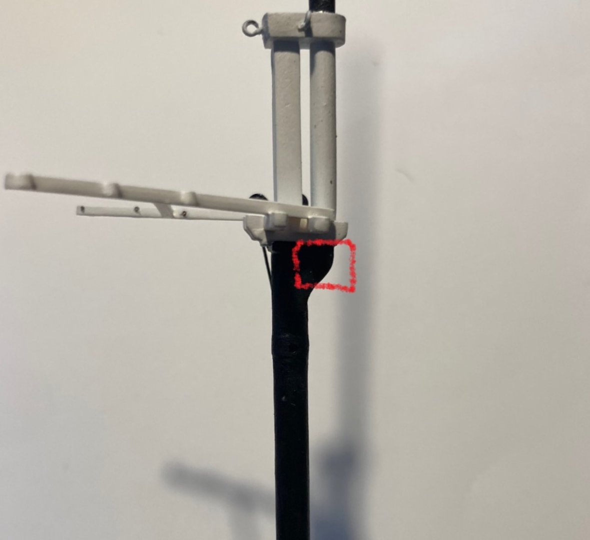
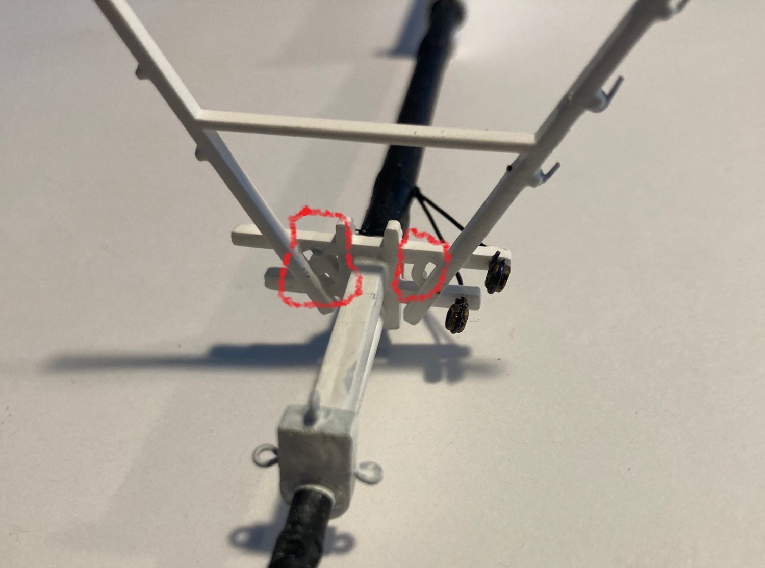
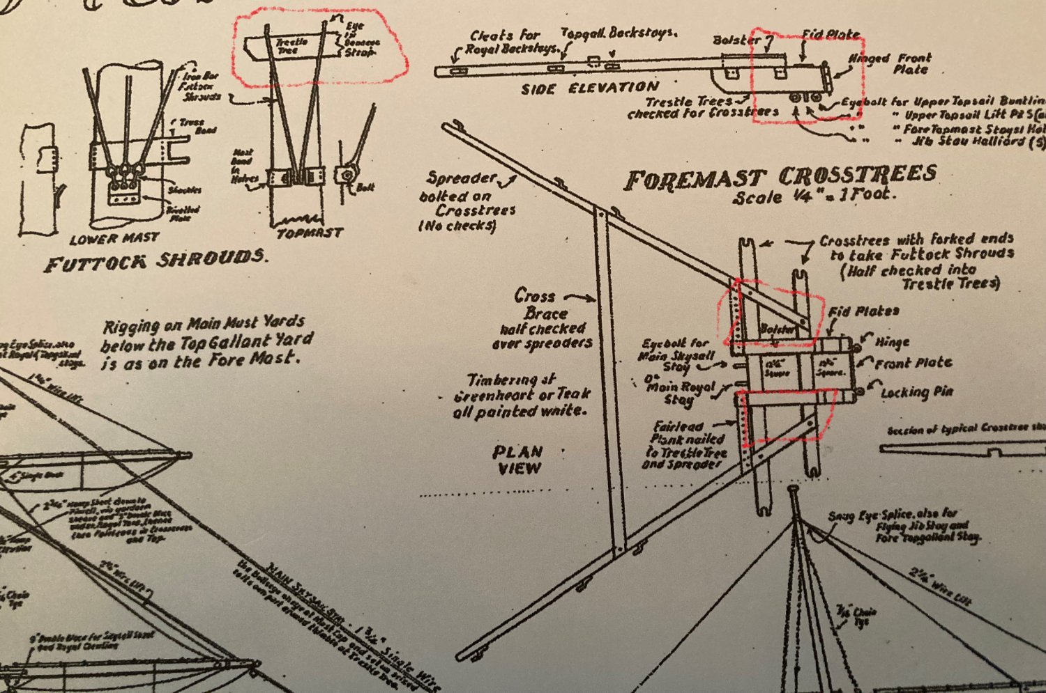
According to Underhill, the trestle-trees, cross-trees, and spreaders are all lengths of angle-iron. The trestle-trees are riveted along the top edges of cheek pieces which are triangular and are centred on the lower mast i.e. they project both forward and aft of the mast. Hard to see them in your dark revell mast but the shape doesn't look right. They shouldn't have that re-curve along the forward edge like wood cheeks on a wood mast. I'd say that cheeks are required, I can't imagine just riveting angle iron at the single point where it meets the round mast.
I agree that those bits of plastic between the cross trees should not be there.
Other than the cheeks Underhill agrees with Campbell in all other respects.
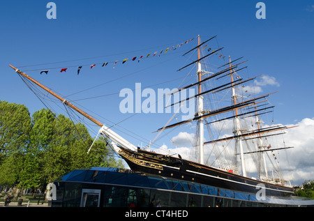
On the other hand I don't see cheeks in this photo although it's hard to see at all. If they are there then they're painted like the mast.
My guess is that the masts and parts were changed over time. The masts were shortened as were the yards and the stunsail booms were removed. Quite possibly the trestle trees were changed also. I'll never know. Underhill and Campbell and Longridge are all different. There is no room for Campbell's eyelets under the trestle tree with cheeks there.
-
I think I see another conflict between Revell and Campbell. Revell has cheeks under the topmast trestle trees like the lower tops. Both Campbell and Longridge do not have cheeks there. Also, Revell's trestle trees have bits of plastic where there should be open space between the spreaders and cross trees. I think that these should be removed.
Anyone agree?
-
2 hours ago, rwiederrich said:
Add all the padeyes and rollers.....they were still present even though they may have not been in use during lengthy periods at pier side. Sometimes the leach and buntlines were brought down and even their blocks...and at other times the lines were brought down but the blocks remained. It all depends on the length of your stay and how fast you want to rig and bend sails to the yards for getting under way. While the gear was down, ropes were mended and blocks were repaired/repainted/varnished or discarded if beyond repair. Saving the gear and tackle from the weather was paramount if it was going to be a long stay.
They would even rig and unrig stunsail booms and rigging often during a voyage. Sometimes often even during a single days sailing.
Rob
That would make sense. Whether the lines were there or not, the padeyes and rollers would be. Cutty Sark sat at Sidney harbor for 3 months at times waiting for thr wool to arrive, Which makes me wonder why the hurry to get there to wait. It's like when I was in the army, hurry up and wait.
-
I have been working on the fore mast. I am adding eyelets and deadeyes per Campbell. I am not sure which ones to add and which to not because I am doing a harbor rig, not sailing rig. Meaning, I won't be adding all the sail handling lines. As I go, I have to research everything, having no experience in rigging a ship.


-
-
-
I finally completed the molding around the base of the deck houses. I have been putting it off. That completes the building of the main body of the ship except for the navigation lights. I am waiting to rig the deadeyes near where they go to mount them.
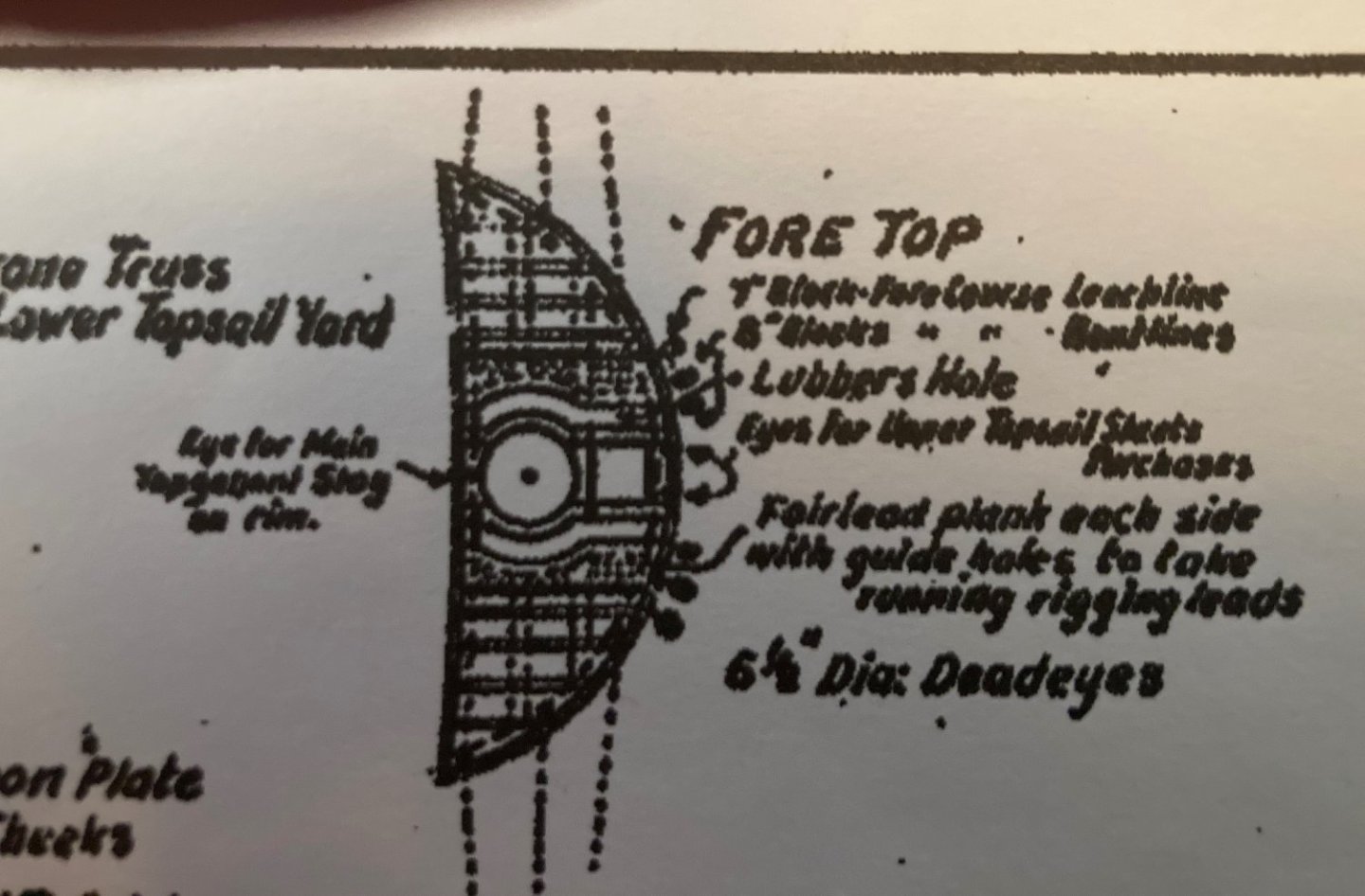
I have been studying the rigging. I want to detail the masts off the ship, which is what I am currently working on. In doing that, I want to replace the plastic "eyes" on the tops with metal eyelets, but I am not sure where to put them. I need to understand the rigging that attaches to them before I can understand where they should be placed. I don't think duplicating Revell's placement is accurate enough.

-
Today I learned that I will have back surgery on the 20th of this month. I will be more, or less, chair bound for a long while. I hope to use that time to rig my ship. So I will return for sure.
-
-
-
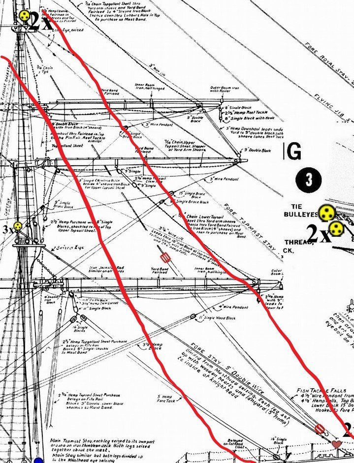
Campbell does show a fish-tackle. I suppose it is up to the modeler to add it or not.


.jpg.998564c89a5b7fc8aaaa783bbc8fb620.jpg)

.jpg.ca5dbea71bbf0b484145bc5b35960bc7.jpg)

.jpg.755055b332904e8168a16029491f3d9f.jpg)


Robert E Lee by bcochran - FINISHED - Pyro - 1/163 - PLASTIC - steamboat
in - Kit build logs for subjects built from 1851 - 1900
Posted
I am experimenting with an idea to fasten the deck to the hull. I may screw them together. The screw takes the place of a clamp to hold the two pieces together. The screws are placed where they won't be seen when the structures are added.
So I would add a series of screws along the center of the deck where they don't show. It is important to drill the screw holes in the right place. My first hole was not correct.
They also hold the parts for gluing. I may remove them when the glue is dry.