


marktiedens
-
Posts
1,737 -
Joined
-
Last visited
Content Type
Profiles
Forums
Gallery
Events
Posts posted by marktiedens
-
-
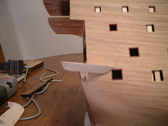
They seem to be an acceptable fit - still fiddling with them.
Mark
- Keith_W and Greg.Ashwood
-
 2
2
-
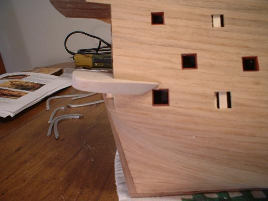
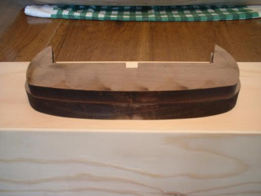
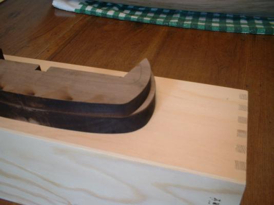
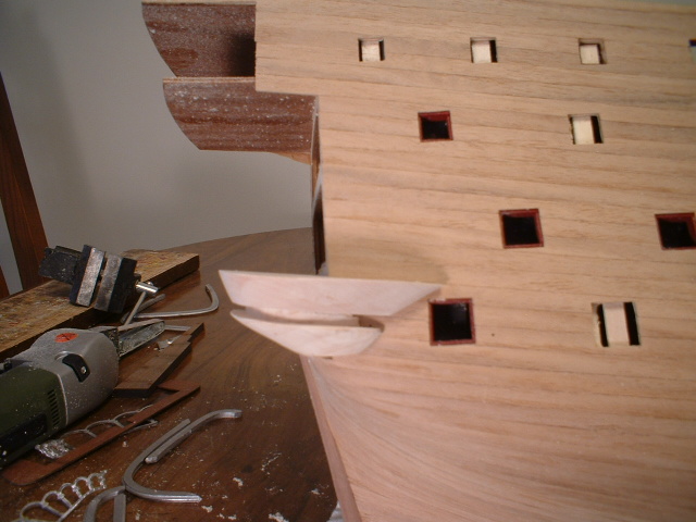
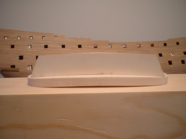
Well,here is transom support version 2.0 - better angle on the rear edge,more room for the gun port,& lower piece re- cut for the metal bands. I am pretty happy with it now. Gotta love these re-do`s.As always,thanks for looking in & hitting the like button
Mark
-
Thanks,Frank. Yes,this is not your ordinary run of the mill kit. Many parts have to be formed & shaped with the materials provided so it is a bit of a challenge.
Mark
- md1400cs and Greg.Ashwood
-
2
-
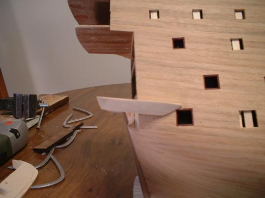
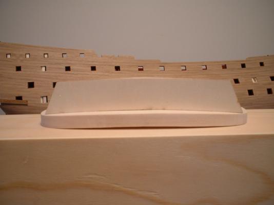
Well,I decided to modify those stern pieces a little further. The upper piece should have a bit of a slant at the rear edge instead of perfectly vertical,so out with the belt sander & beveled the rear edge. Much better now I think. Thanks to keith w for the heads up on this. Now I have to modify the bottom piece to fit again,which means re-carving those grooves for the metal bands.
Mark
- Greg.Ashwood, Keith_W, NMBROOK and 2 others
-
5
-
First,Thanks for all the nice comments.
Pete - That sounds like it may be a good idea to pre-bend at least the lower wales. 2 by 7mm walnut is a real pain to bend.
Keith - I was considering installing the wales before the transom,but did not want to try & chisel parts of it out while at the same time trying to fit the galleries. I also thought about just installing the lower wales first,but I didn`t know exactly where to end them under the transom. They appear to end in a curve to match the bottom decoration,which can`t be put on until the transom supports are i place. I am considering making the lower wales out of basswood - much easier to bend. Since they will be painted black it doesn`t really matter what kind of wood they are. The only trouble with using basswood for the wales is I would have to be careful not to ding them up - basswood is kind of soft. I may try to bend those walnut strips first to see how they come out. I remember when I built the Wappen Von Hamburg the lower wale was 3 by 8mm walnut - talk about hard to bend.
Mark
- Seventynet, Keith_W and Greg.Ashwood
-
3
-
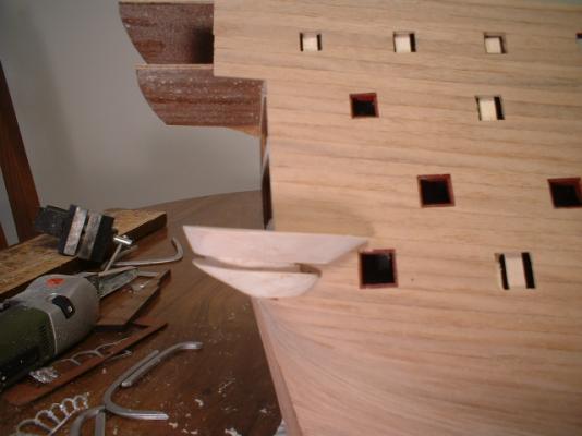
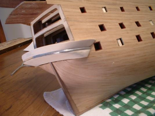
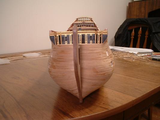
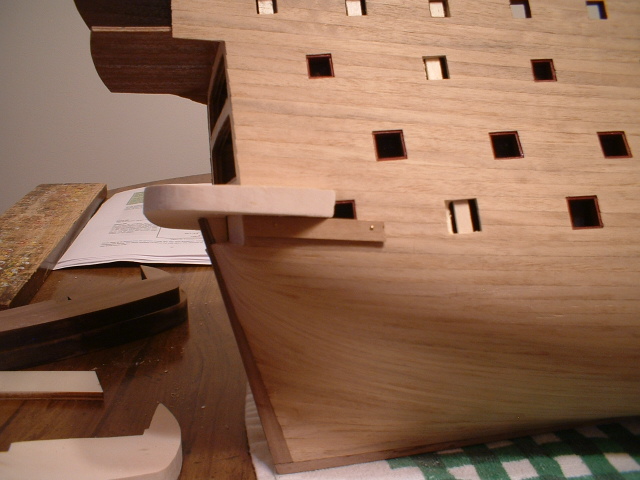
Hi all - moving forward on the transom. After studying the plans & Pete`s info I started with the upper transom support,which is the base for the entire stern assembly - it needs to be close to correct or everything will be off. First thing I did was attach some short planks in the position of the lower wale - that way I could slide the transom support in to the same place every time while fitting it to the sides of the hull.

Then after fitting to the sides of the hull I installed a couple of dowels in the front edge so I could install it in the same place after removing the 2 short planks. The distance from the top of the upper support was 98mm - just what it should be to the upper quarter deck.
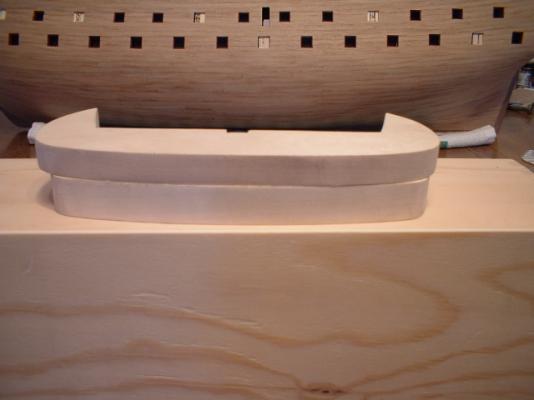
Then I proceeded to shape the upper transom support. I used the metal bands that fit between the 2 support pieces as a guide to shaping the bottom.The profile of the top of this piece was not altered.
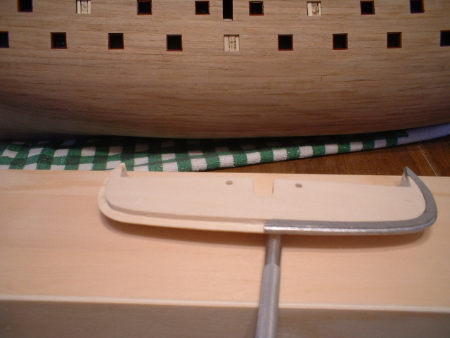
Then I shaped the lower support both from the sides of the hull & the bottom of the upper support. Then the fun part - cutting the groove for the metal bands to sit in. Took most of a day with my little exacto chisel & files.Meanwhile, I installed 2 dowels to keep the 2 pieces in alignment. A dry fit of the 2 support pieces & metal bands came out pretty good.
My hand held Proxxon belt sander was a BIG help in shaping these pieces.
Mark
-
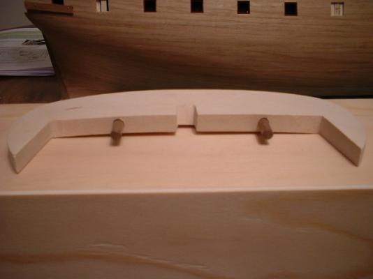
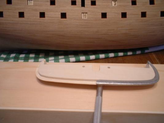
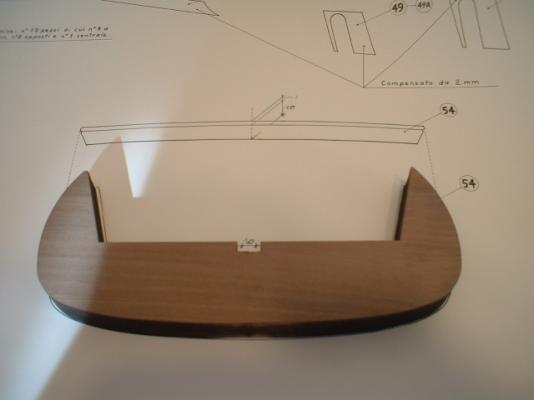
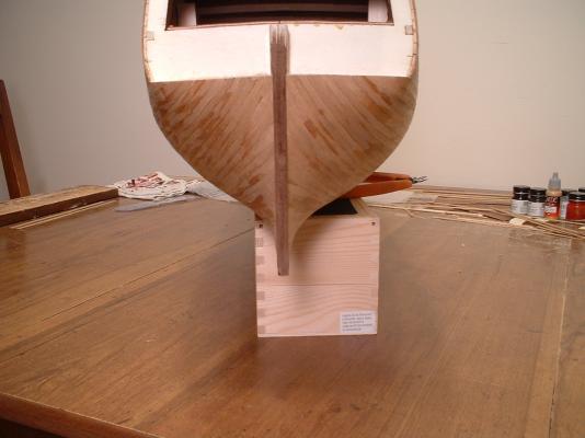
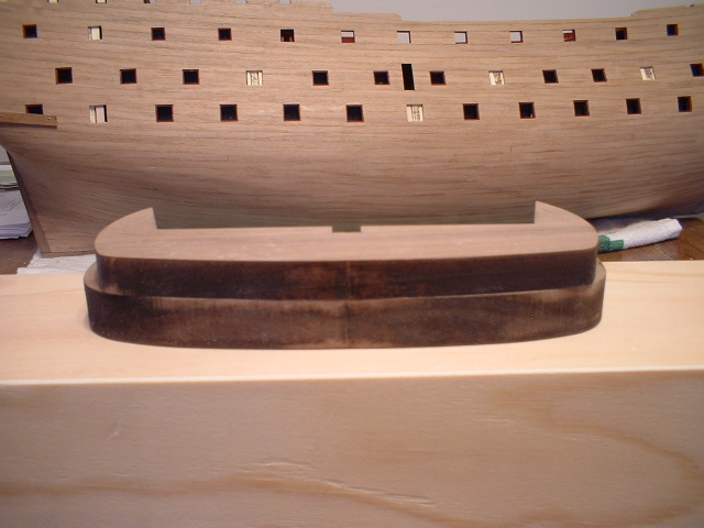
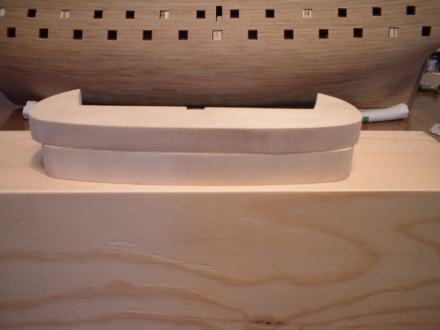
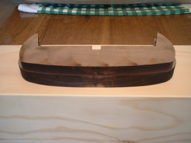
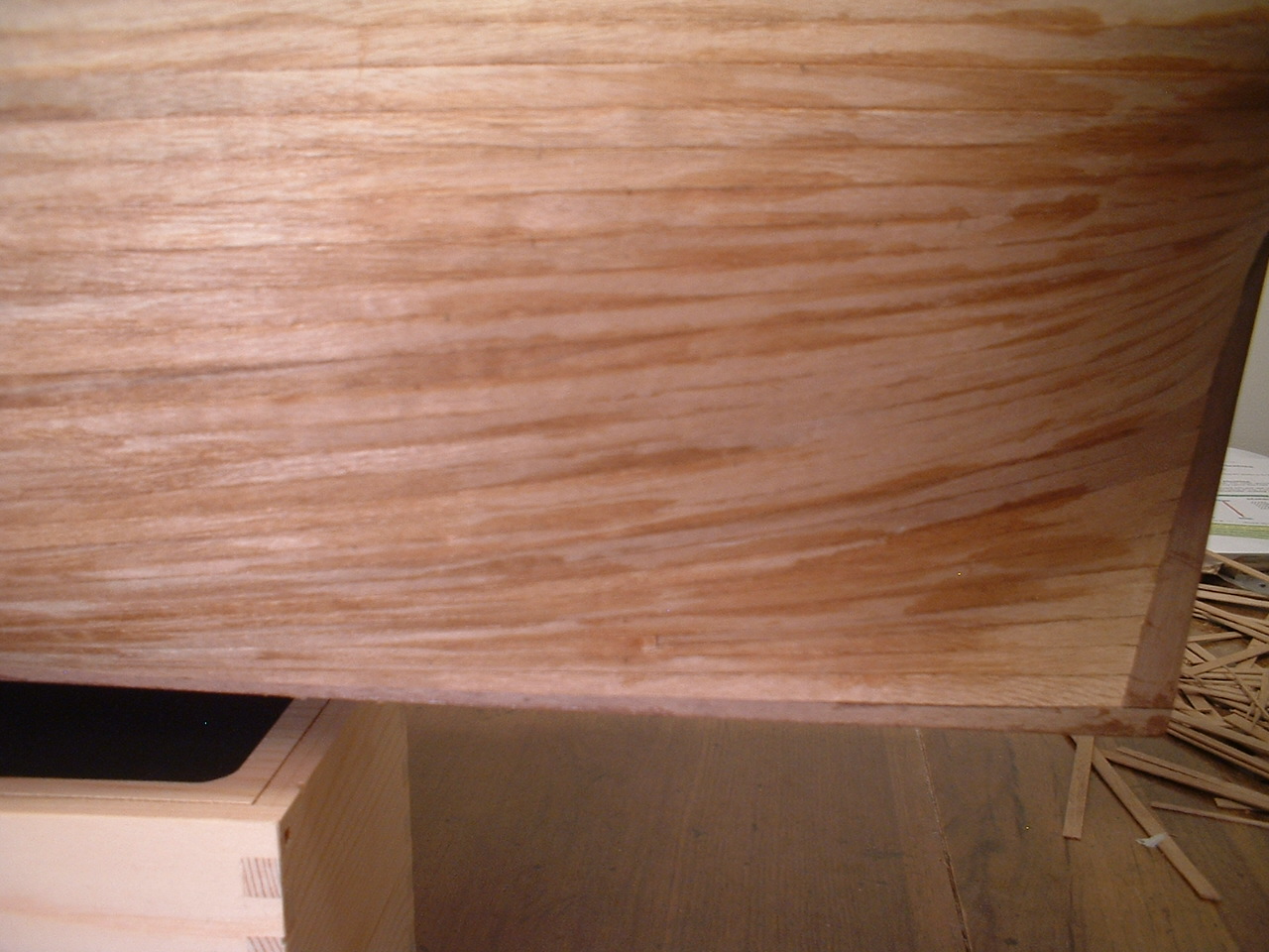
Update - started working on the transom & ran into a problem. After a lot of measuring & head scratching it seems the 2 main pieces that make up the transom support were made wrong. After contacting piratepete007 - the writer of the interpretive manuals - he contacted Euromodel & found out that a few years back the people doing the laser cutting cut a batch of these timbers the wrong thickness. I was going to contact them for some replacement parts but decided to just make new ones - not too difficult. In the first picture you can see the 2 parts sitting on top of each other,the thicker one on the bottom as it shows in the plans & Pete`s info. The problem is the thinner top piece should be wider than the bottom one. The second picture is of the new pieces I made. Finally,in the last picture I used one of the bulkhead knock-outs as a template to form the correct deck camber on them. Euromodel knew about the bad parts,but someone unknowingly put them into some kits. I guess I am a perfect example of Murphy`s law.

Mark
- fmodajr, Seventynet, MarisStella.hr and 4 others
-
7
-
Keith - as far as the wales go,I laid the first strip of the second planking at the position of the top of the lower wale & with the same curvature so lining up the angle of the transom pieces should not be a problem. As far as shimming the 2 transom parts,Pete says that after beveling for the camber the parts should end up with thicknesses of 10.5 & 13.5mm along their entire width. Will the assembly of these 2 parts not be high enough if I don`t shim them?
Mark
-
Hi Keith - that is my determination also. I have been in contact with Pete about this. He is going to contact Euromodel about this,but I am going forward & in the process of making new parts out of basswood. The basswood is a little easier to work with than that rock hard walnut anyway. Here are my nice new parts & thanks for your help & opinions

Mark
- GLakie, UpstateNY, thomaslambo and 2 others
-
5
-
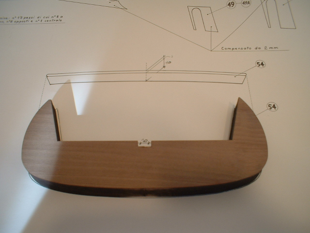
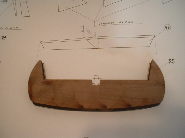
Hi Keith - I took a couple of pics to show what I mean. The first pic has the thicker piece set on the plan sheet on top of the top profile,which matches perfectly. If you look at the side profile just above it,it appears that it should be the thinner piece. The second pic has the thinner piece set on top of the top profile of the plans & matches perfectly,but the side profile above it shows that it should be the thicker piece. In other words,the pieces are shaped correctly but the thicknesses are reversed. Also if I set the thinner piece on top of the thicker one,it is a bit narrower. Does this look correct to you?

Mark
-
Hi Keith - I have a question for you - when matching up the pieces 54 & 55 with the plans piece 54 appears to be the 18mm thick piece,while 55 appears to be the 13mm thick piece. My issue is that Pete`s info seems to indicate that 55 is the thicker piece & 54 the thinner one
 . It also appears that way in a drawing on page 25 of manual 2 of his info. which is correct? I guess what I really need to know is which piece goes on the bottom? Also on plan sheet 7 the top profile of piece 54 matches the thicker piece but on the side profile it looks like the thinner piece. The top profile of piece 55 matches the shape of the thinner piece but the side profile looks like the thicker piece
 Mark
-
-
Thanks Ian - those gun ports were a bit fiddly to do,but I am happy with them.
Mark
- Greg.Ashwood and Seventynet
-
2
-
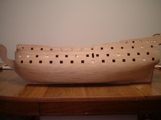
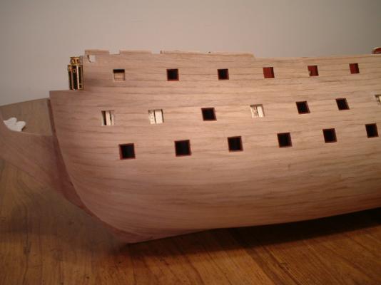
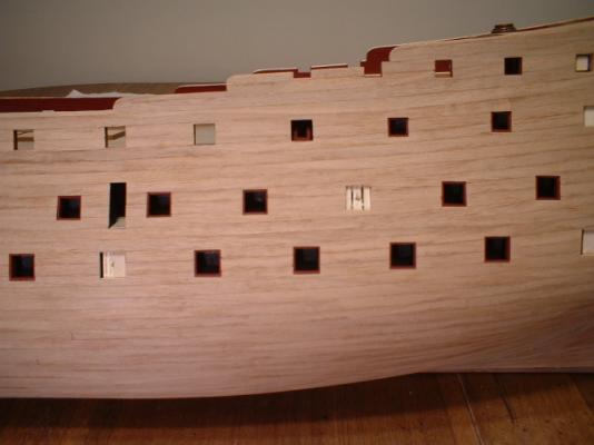
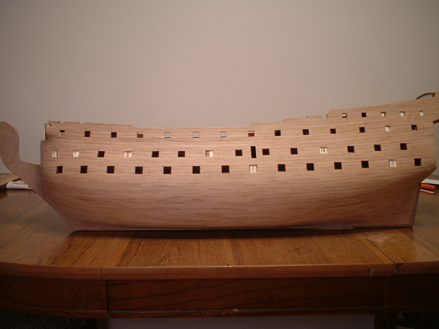
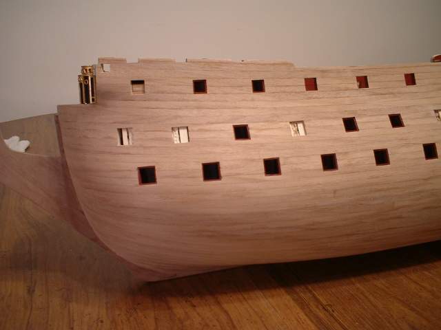
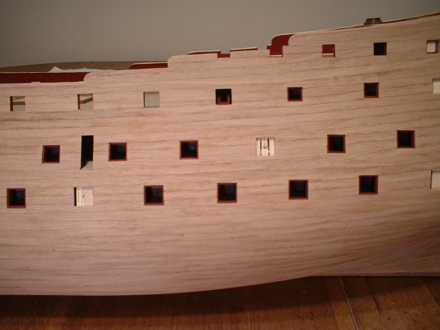
A little more progress - planking all sanded down smooth & all gun ports that will be open are lined. I pre-painted the 1 by 5 mm strips for the linings before installing them - much easier than trying to paint them in place. No finish has been applied to the hull yet so it looks a little dull. Next up will be the stern galleries.
Mark
- fmodajr, Seventynet, canoe21 and 3 others
-
6
-
-
Thanks Michael - your thoughts are appreciated.
Mark
-
Hi Max - I recall the Wappen Von Hamburg by Corel also had square strips ti make the masts. They were already tapered so all that was needed was to round off the corners with a small plane & some sanding. Check your square bars for the masts - they may be pre-tapered also.
Mark
-
Greg - thanks very much. Sanding is underway!
Jason - thanks also. I really like that bow shot too. The bow is rather bluff,so a bit of edge bending was required but it came out ok. I did not need any drop planks.
Mark
-
Frank - thanks very much. Glad to get that part done.
Janos - thanks very much. Actually I was just joking about needing a stealer - I originally thought I would need 2 or 3
 .
.Ian - no offense taken. I am always open to suggestions or constructive criticism.
Peter - thanks also for your nice comment.It is one big ship - I haven`t figured out where I`m going to put it when finished.
I have scraped,sanded,scraped some more,& sanded some more,so it is looking pretty decent now. More pics when I have finished the gun port linings.
Mark
- janos, Seventynet and NMBROOK
-
3
-
-
Thanks Ian - I know I can get it smoothed down ok,it`s just a lot of work
 .After building 20-some ships these are probably the roughest I have come across - they look like they were cut on a 10 inch table saw with a dull blade.
Mark
-
-
Thanks Nigel - I guess it is more than a little update
 . I wish I could have gotten better wood for the planking,but I would have had to spend 2 to 3 hundred USD for better wood like pear or boxwood
  .Anyway,I told myself when I started this build I would try to make the best of the kit parts.I don`t know why the planking strips were cut so poorly while the deck planks were very nice & smooth.
Mark
- NMBROOK and Seventynet
-
2
-
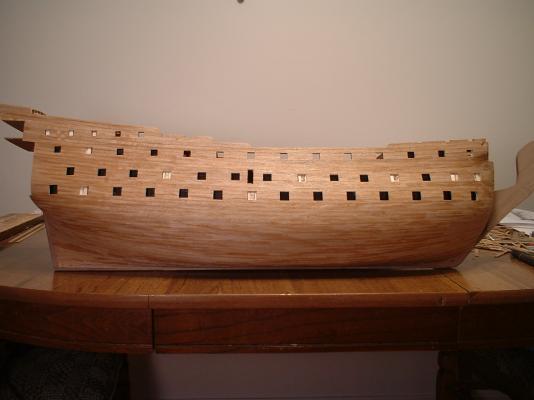
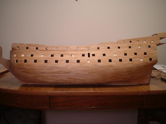
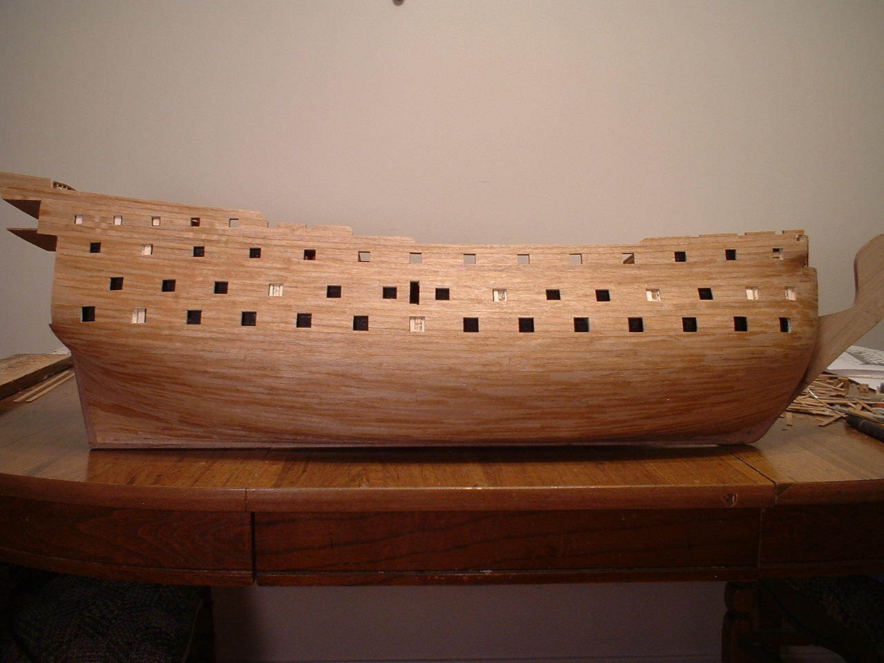
A little update - second planking complete! The wood for the second planking was not the best quality - the thickness & width was consistent but the surfaces were very rough on some planks. A lot of scraping & sanding will be needed. It looks a little splotchy now since I haven`t started any scraping or sanding yet. I was a little disappointed that I had to use one stealer on each side at the stern
 .
.

Mark
- Seventynet, coxswain, canoe21 and 10 others
-
13


Royal William by marktiedens - FINISHED - Euromodel - scale 1:72
in - Kit build logs for subjects built from 1501 - 1750
Posted
Greg - thanks for your nice comment. It has been a bit of a challenge,but I am enjoying it. Best wishes to Greg the peg leg sailor.
Pete - very well said. Along with your info it`s also great that other modelers of this ship can offer each other their observations & suggestions on how to approach different aspects of building it.
Mark