HOLIDAY DONATION DRIVE - SUPPORT MSW - DO YOUR PART TO KEEP THIS GREAT FORUM GOING! (83 donations so far out of 49,000 members - C'mon guys!)
×


yvesvidal
-
Posts
3,607 -
Joined
-
Last visited
Content Type
Profiles
Forums
Gallery
Events
Everything posted by yvesvidal
-
 I agree with you that they are not made of wood. However, wood blocks can be made to look like these insulators, better than a flat PE part. We'll see how that goes. Yves
 -
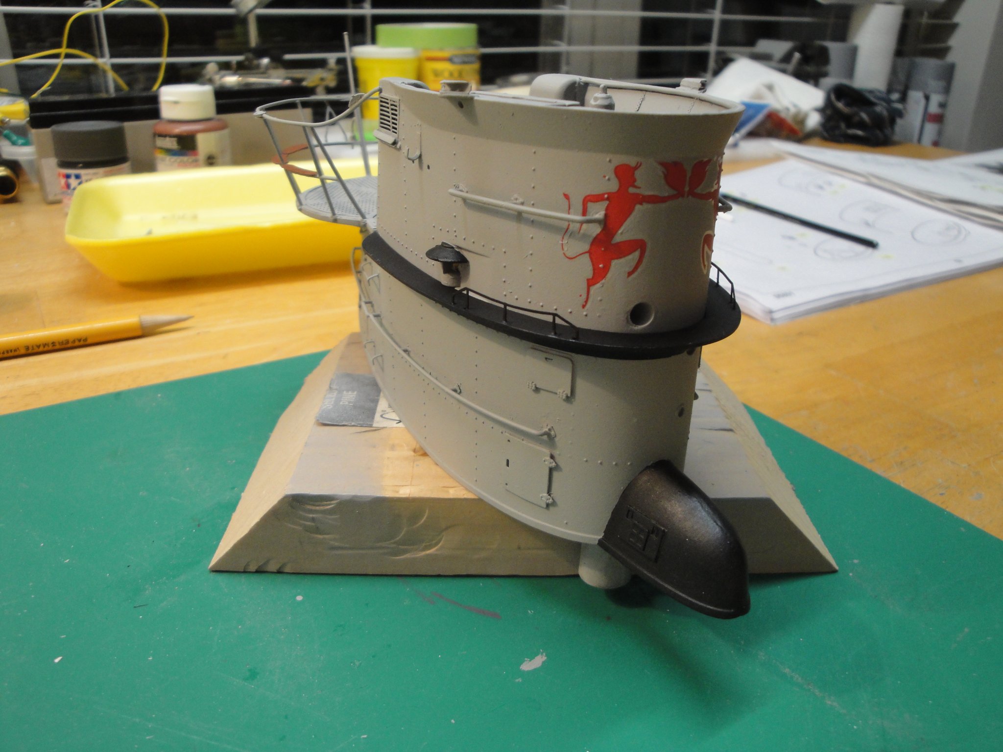
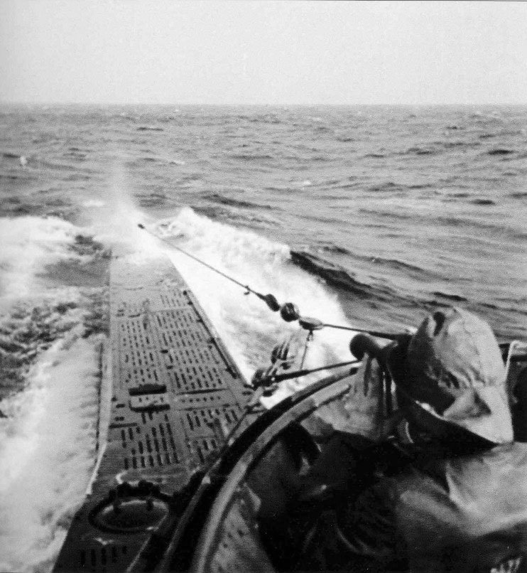
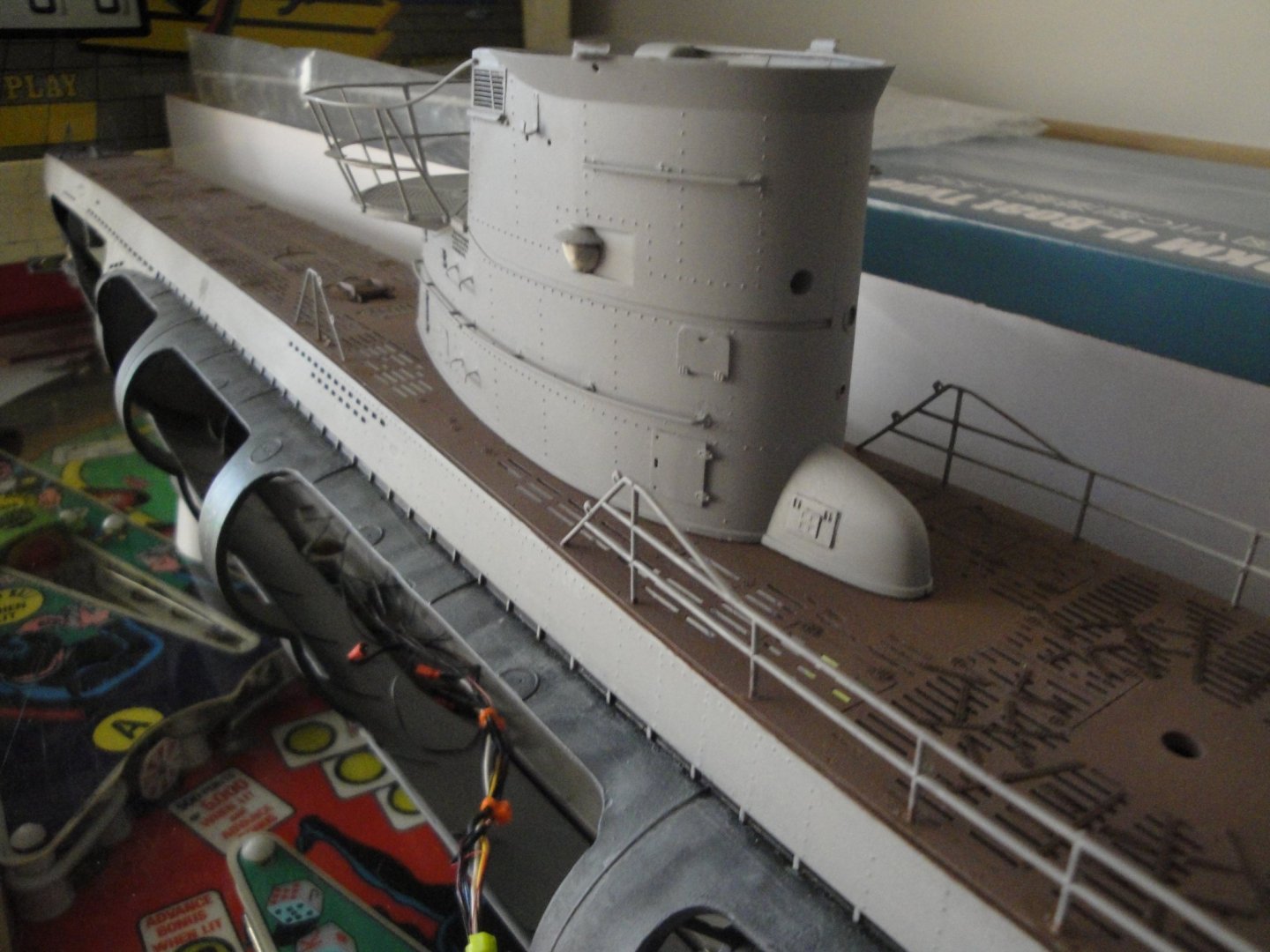
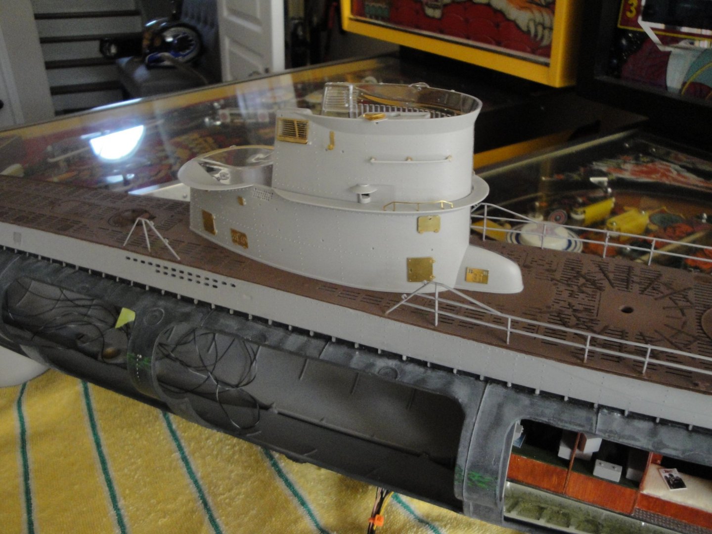
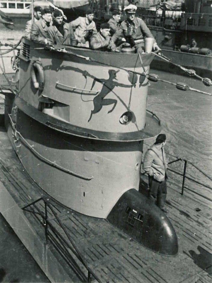
Just a couple of pictures showing the sail in color, and matte clear coated: There is still plenty to do but the lights have been wired and most details installed. I still need to create the lenses (out of clear sprues) for the navigation lights and perhaps do a very subtle weathering. I am representing the vessel in the early days of teh U-552, and as you can see from this famous picture, the sail was very clean: I have ordered some blocks from Syren and will try putting together some of the rigging. That should be interesting. Note that Trumpeter have nothing planned or described about the wires and antennae and I did not purchase the Photo-Etched set from RC Subz for the rigging. As you can see from the picture, the blocks are round and not flat as would be photo-etched parts folded on each other. We'll see how this goes. Another first for me.... Yves


- 760 replies
-
- 16
-

-
Impressive of realism. Fantastic work. Yves
-
Beautiful boat and excellent choice. Yves
-
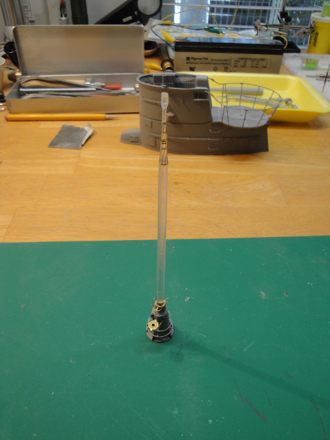
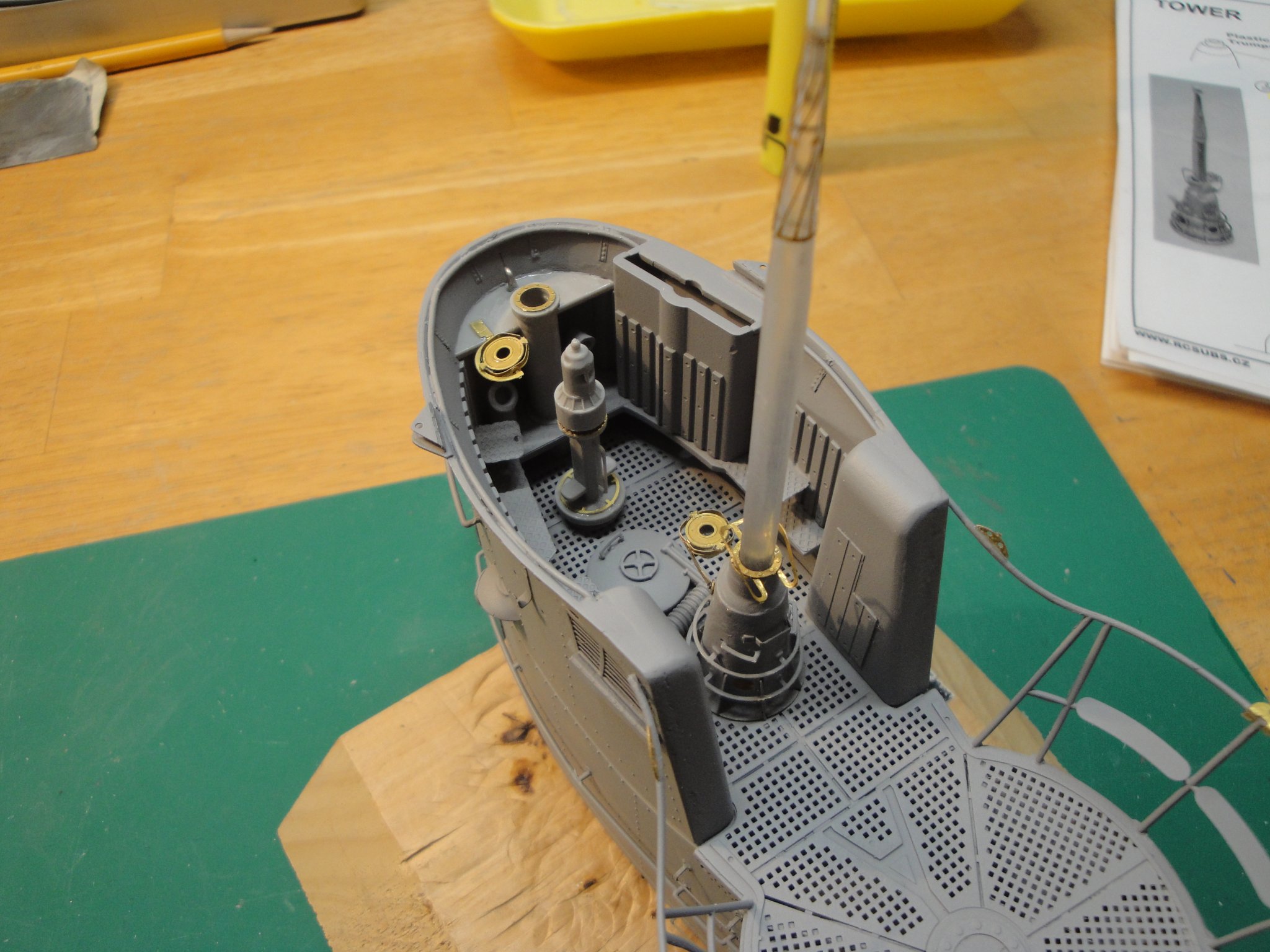
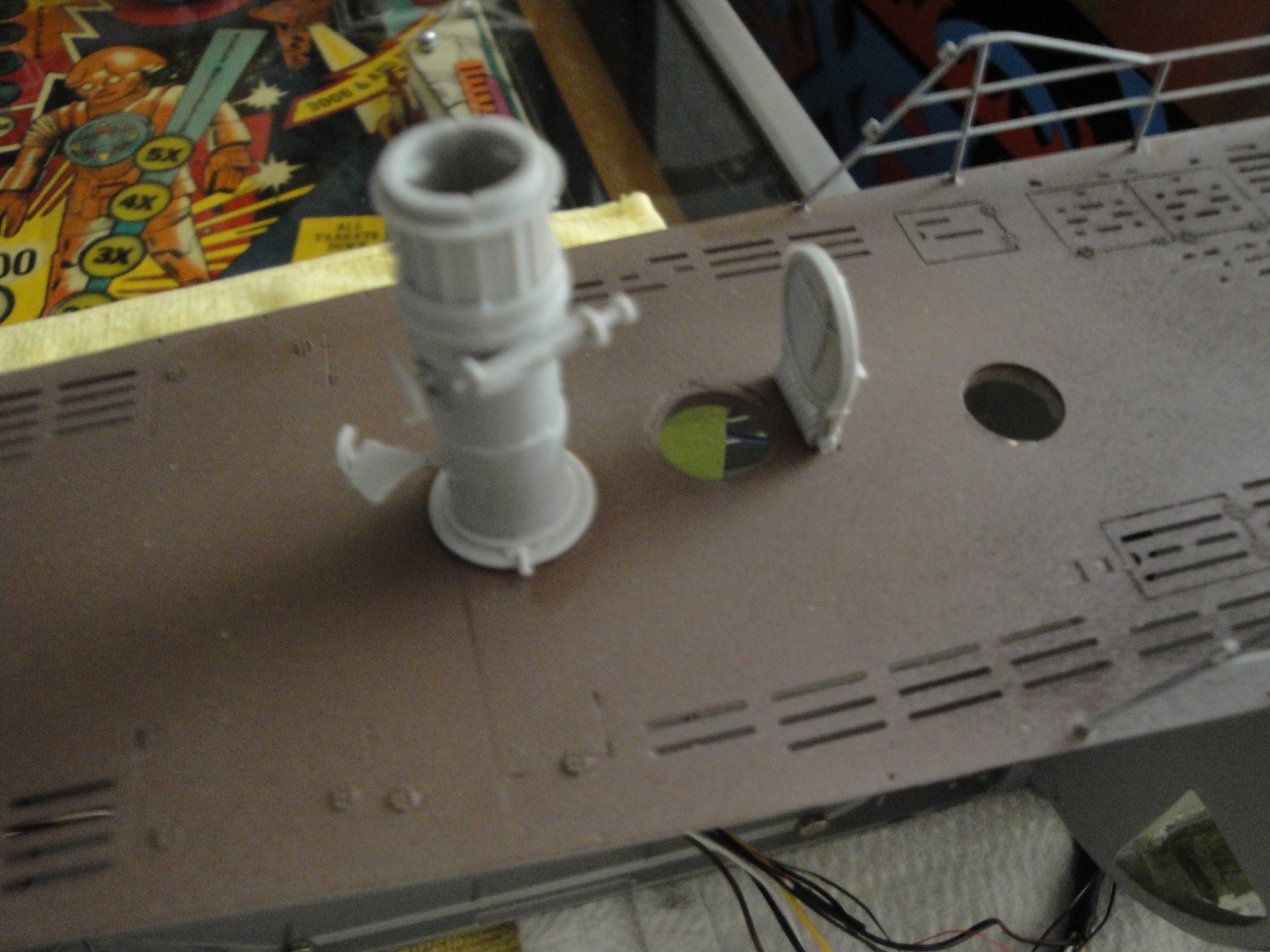
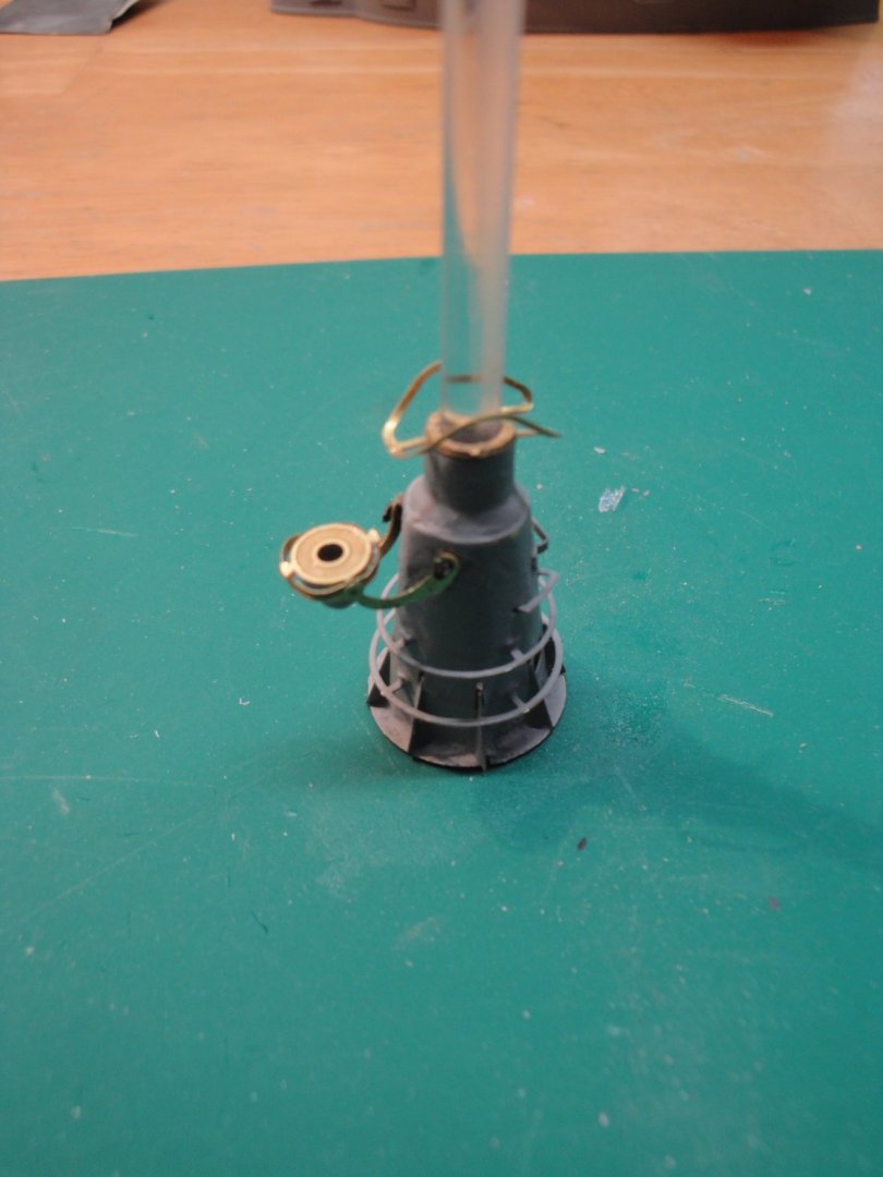
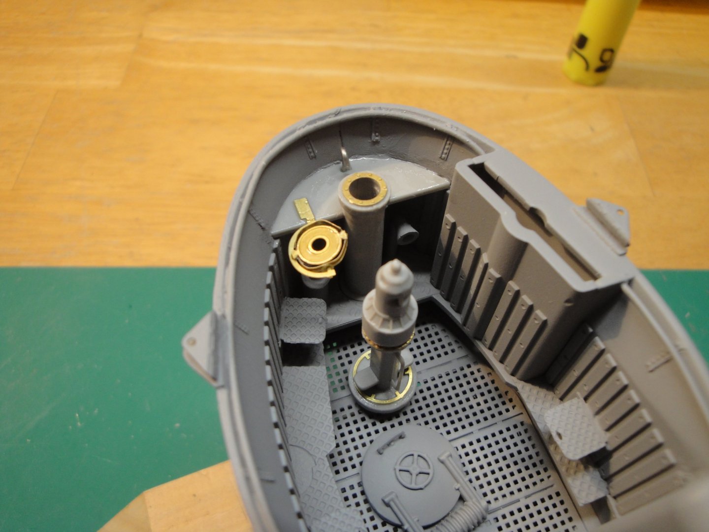
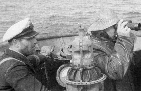
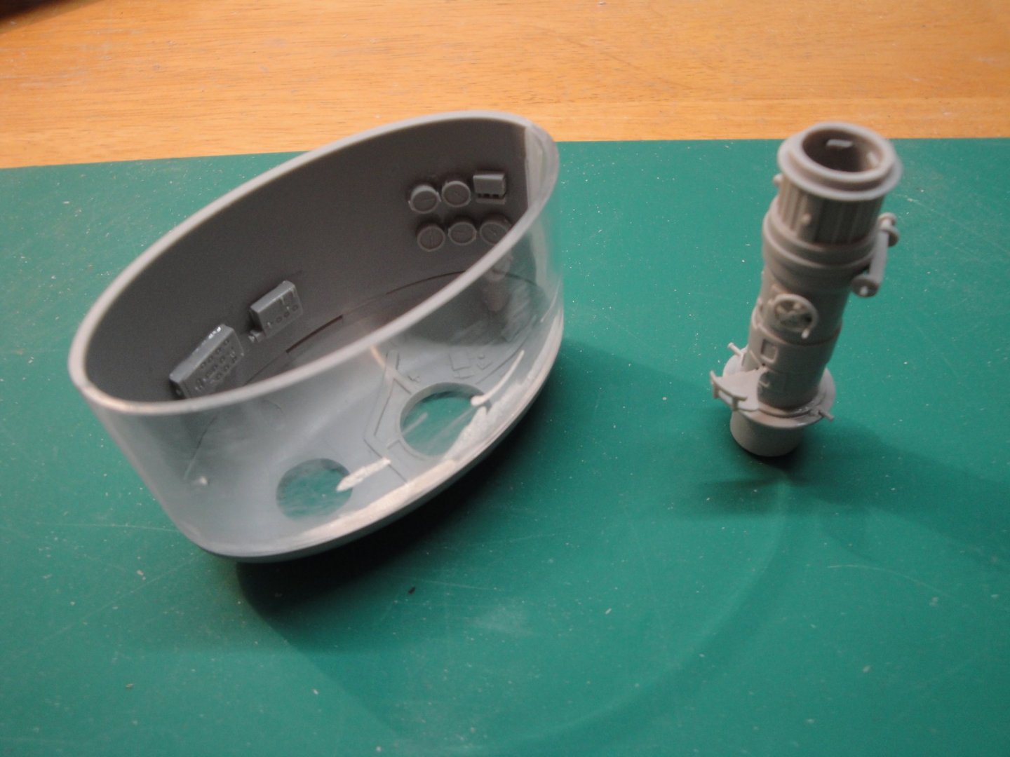
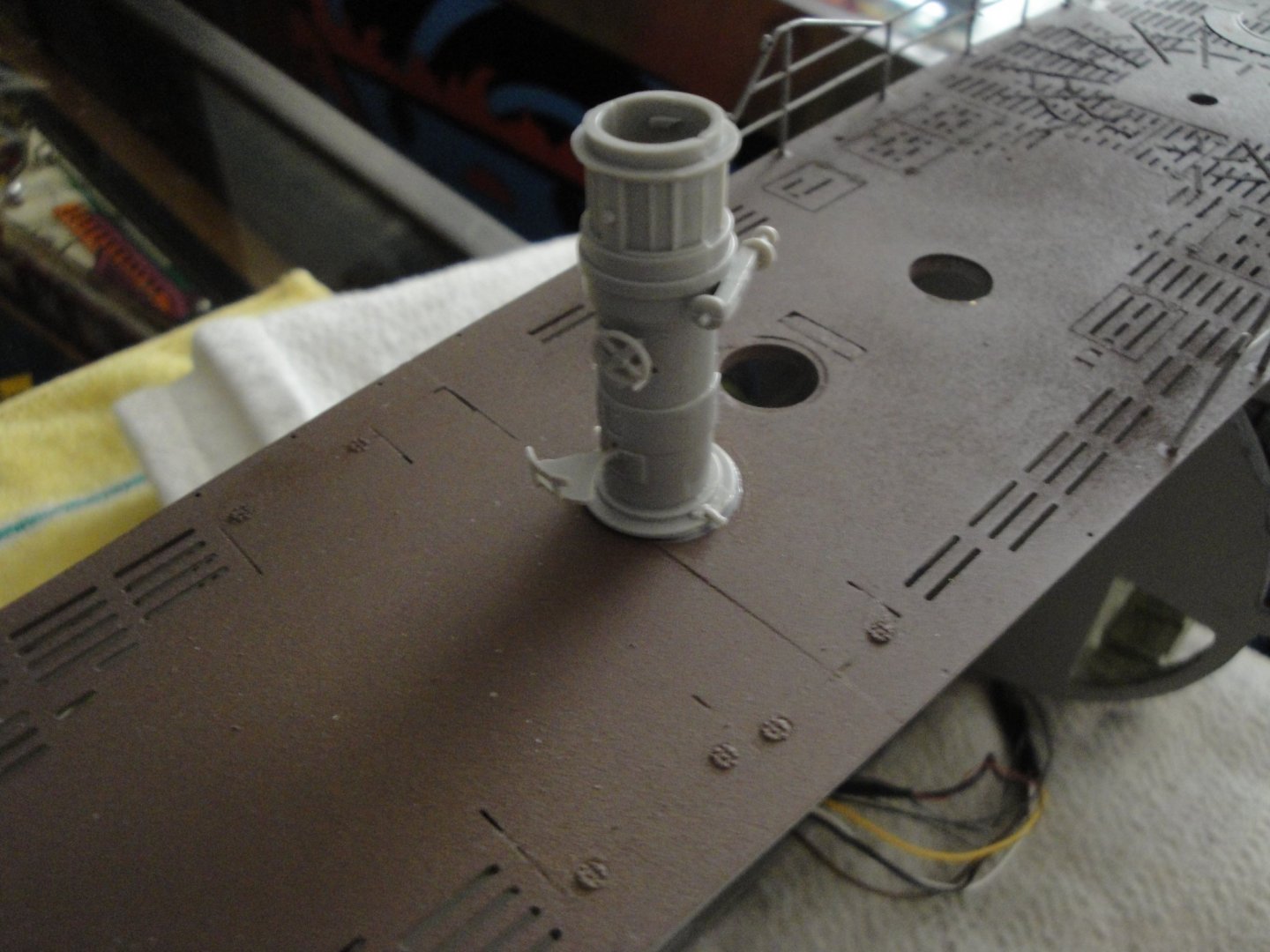
Coming to a closure on the conning tower. First the attack periscope and its strong platform with a compass: Details of the compass. I need to find some print of the compass, scale it down and glue it in place, once everything is painted. Below is the front of the platform: Observation periscope shaft, the UZO holder (used to hold all kinds of pointing devices and binoculars), the round Direction Finding antennae (DF) for taking bearings on beacons and for receiving Very Low Frequency messages from the U-Boot Commander In Chief (BdU). Front Compass: Attack periscope in place: I still need to finish the wiring of the navigation lights, paint the whole tower, decals and final matte clear coating. Yves


- 760 replies
-
- 19
-
-
7Youngs, Yes I have seen this video and the beautiful realization of this talented Chinese modeler. Yes, he did cut out an opening on the opaque side of the sail and swapped the internal pressure hull sections. It is easy to do although unrealistic as you have to assume that both side were symmetrical of each other, which was not the case. The sail is so small, that I decided to skip this operation and kept it "solid". I admire the beautiful casing he did for his model but do not like the blueish color of the LEDs that he used. I wish my model could be as nice as Jacky's beautiful submarine. Yves
-
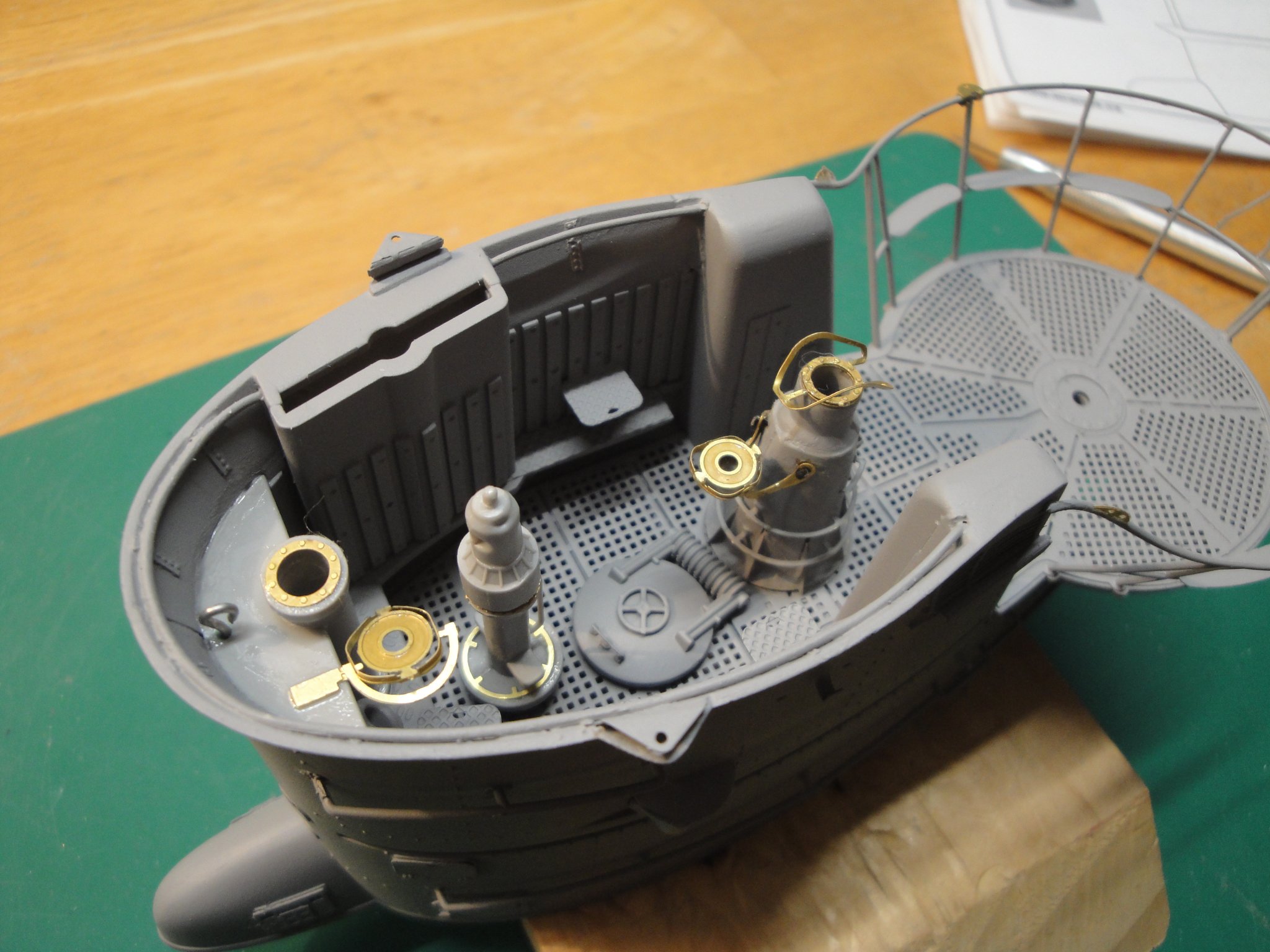
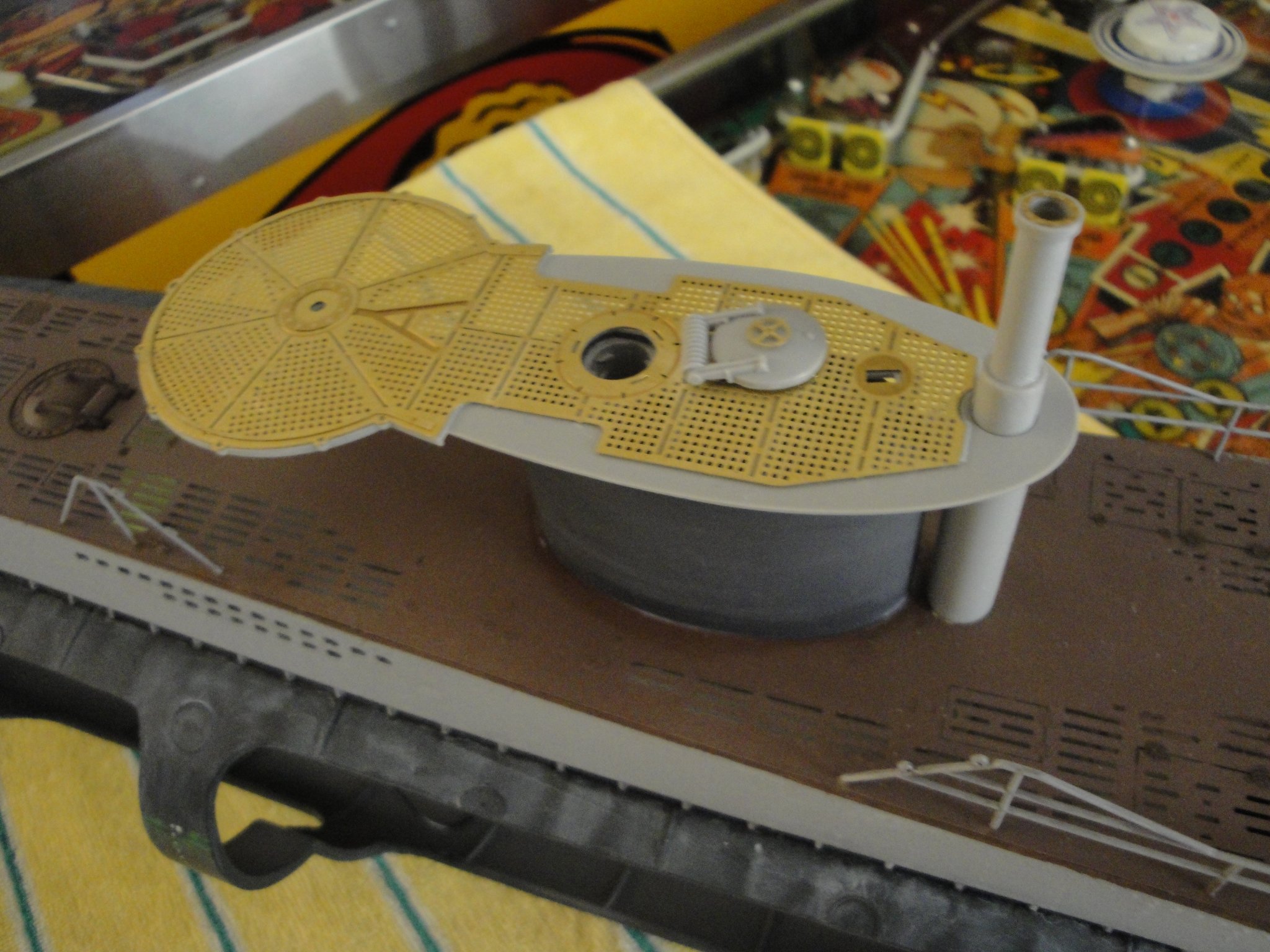
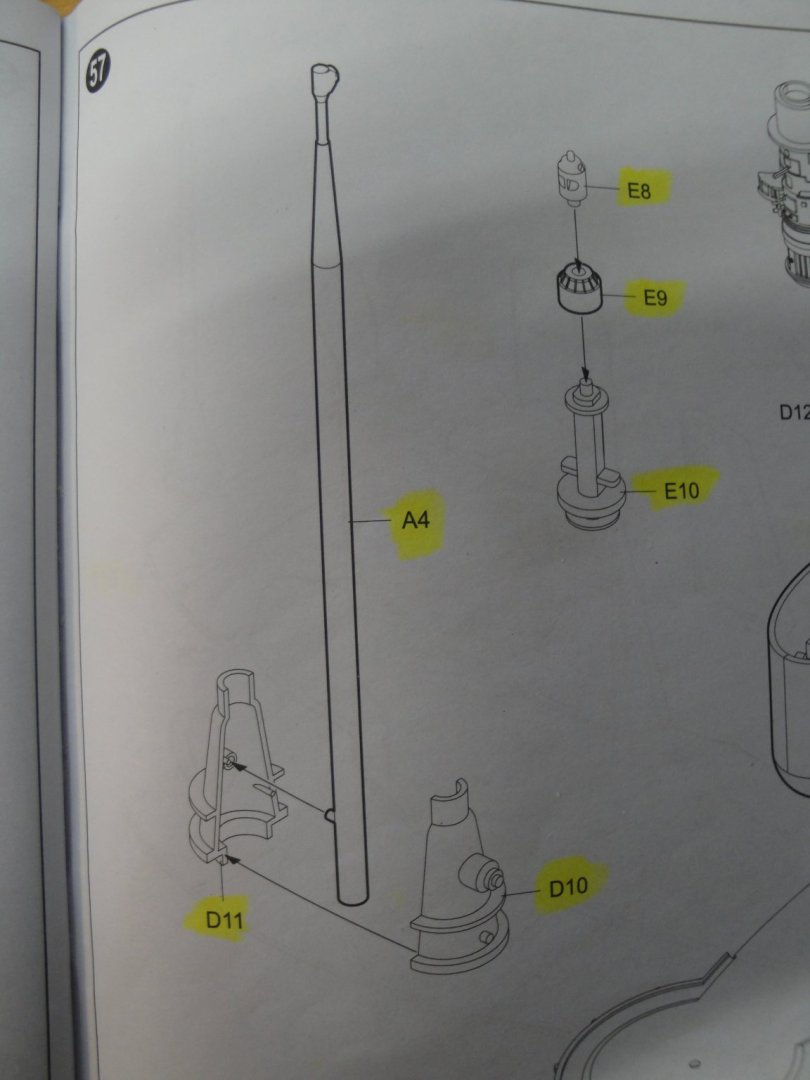
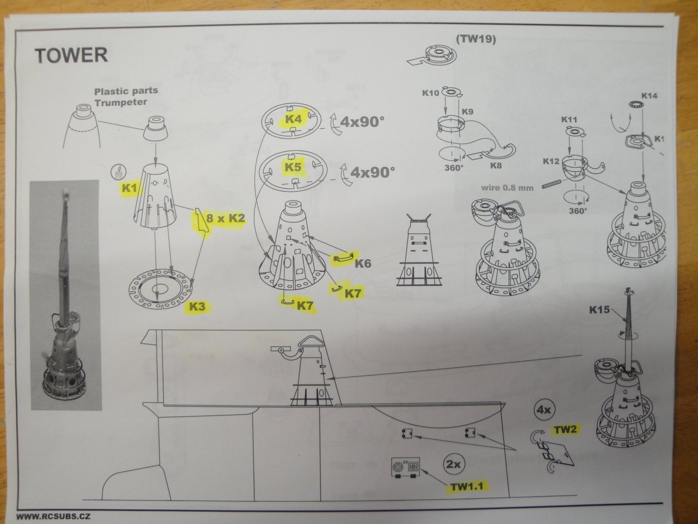
I am working on the periscopes and other details of the conning tower. So, the progress are slow and small. I wanted to share with you some interesting facts about the Trumpeter kit and the real need to invest into a Photo-Etched kit from Eduard or RCSubz. Below is the assembly of the Trumpeter kit for the attack periscope and stand for the UZO (surface attack Optics) and binnacle. As you can see, details have been simply omitted: In contrast, the RCSubz photo-etched set offers many more details with a challenging assembly: I have not looked at the Eduard set, but I suspect they do improve significantly over the Trumpeter kit. So, this is where I stand as this moment: Still adding some small parts to the Conning Tower: Yves


- 760 replies
-
- 20
-
-
Welcome back! Yves
-
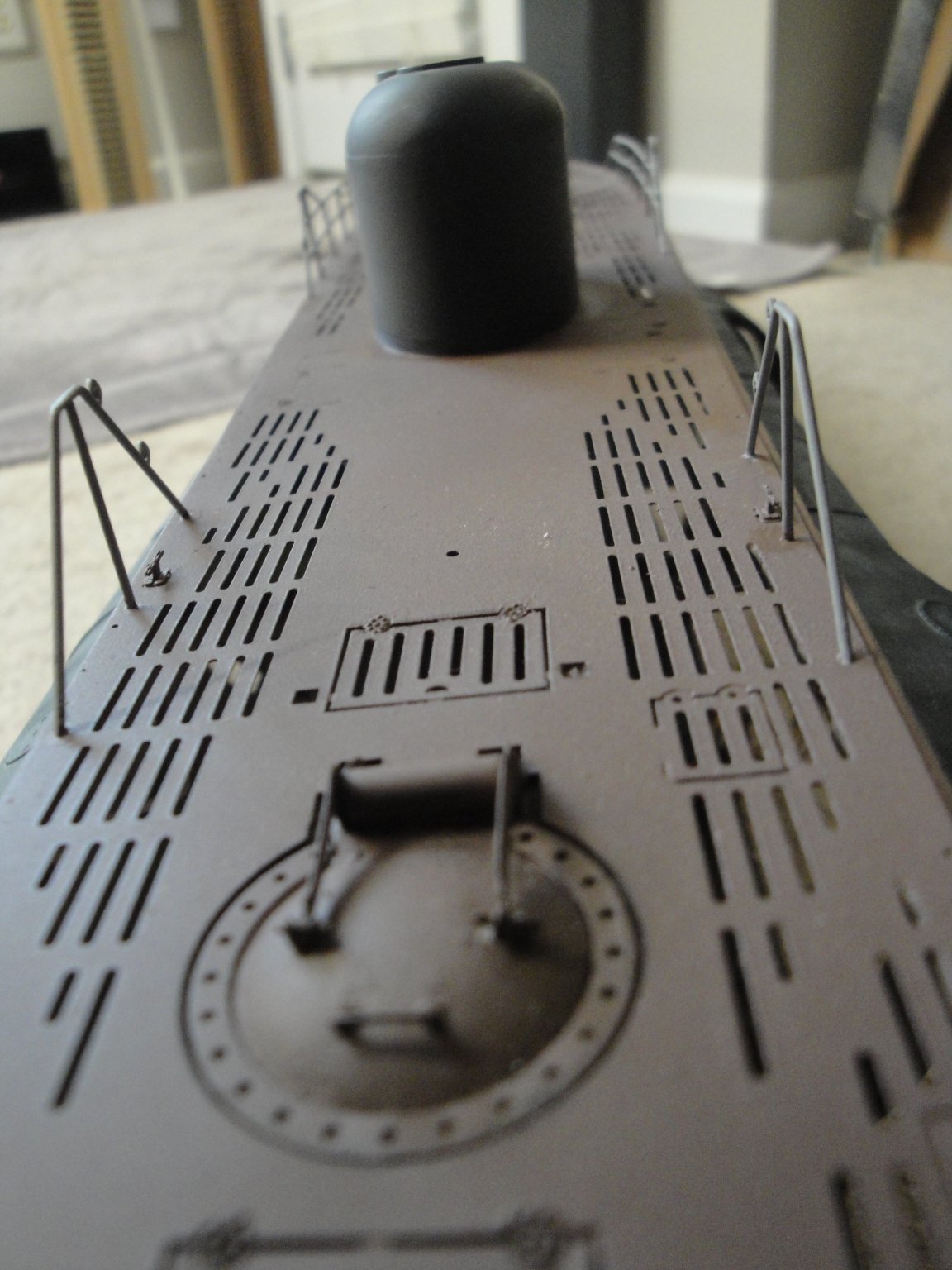
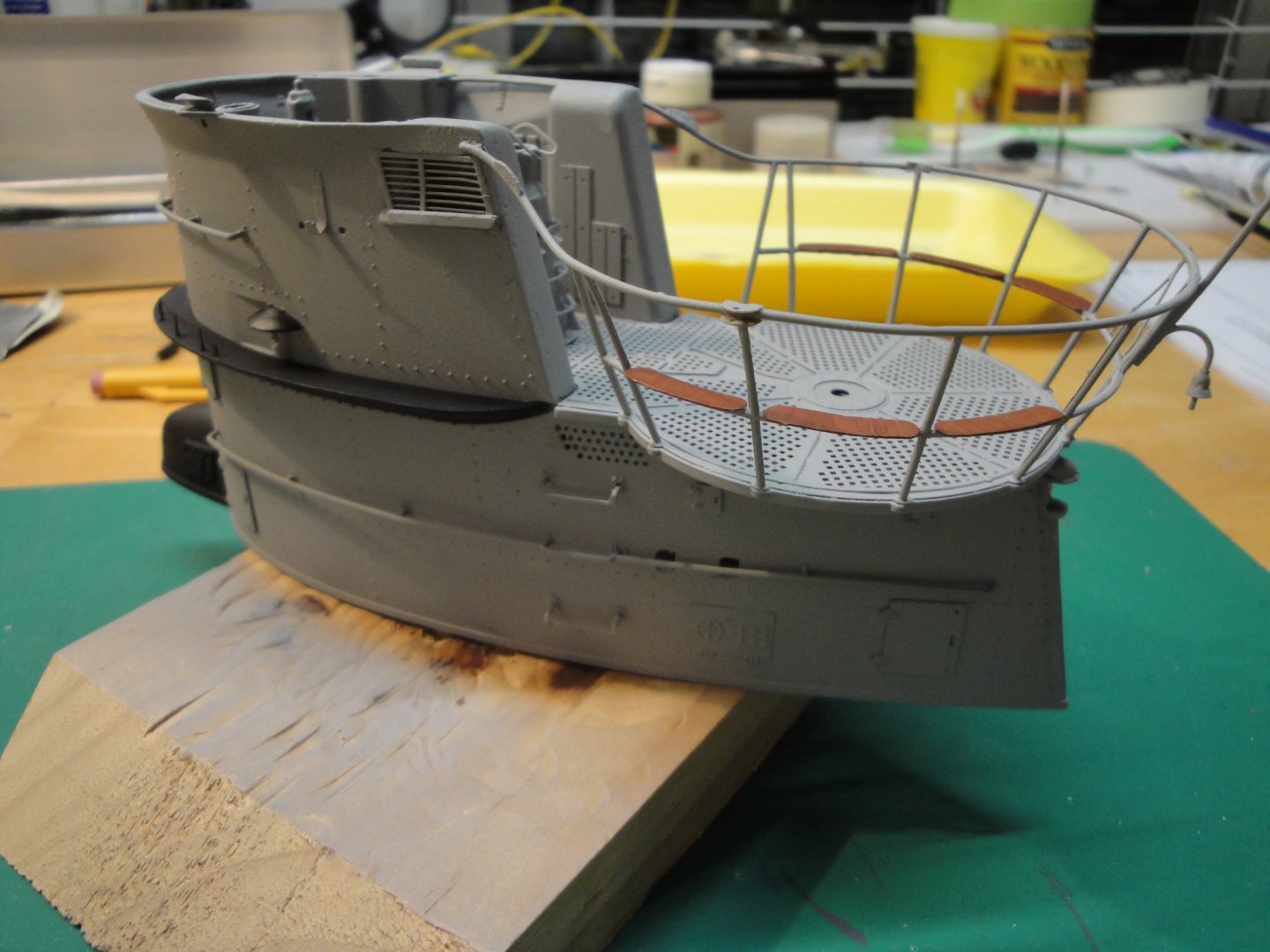
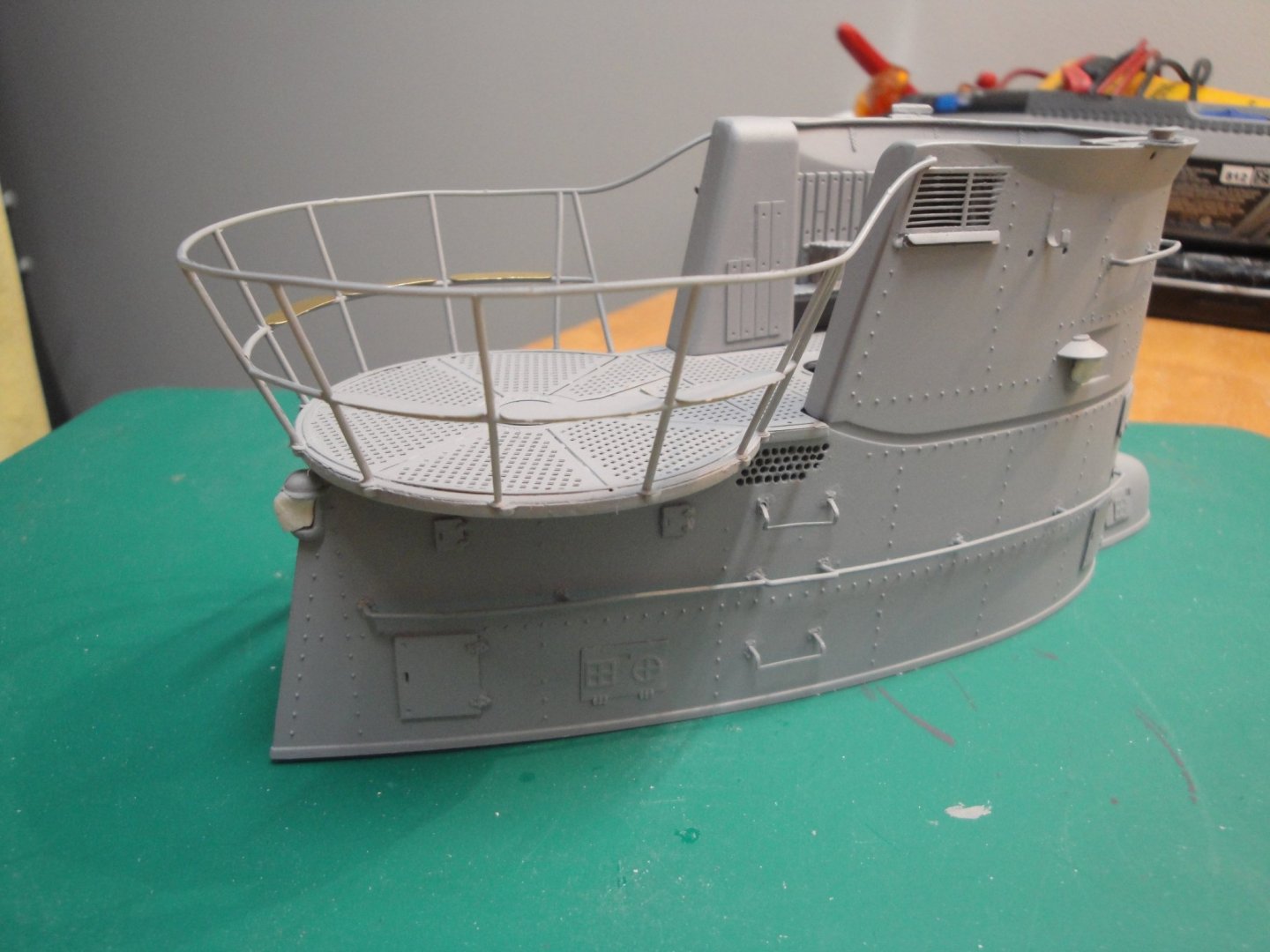
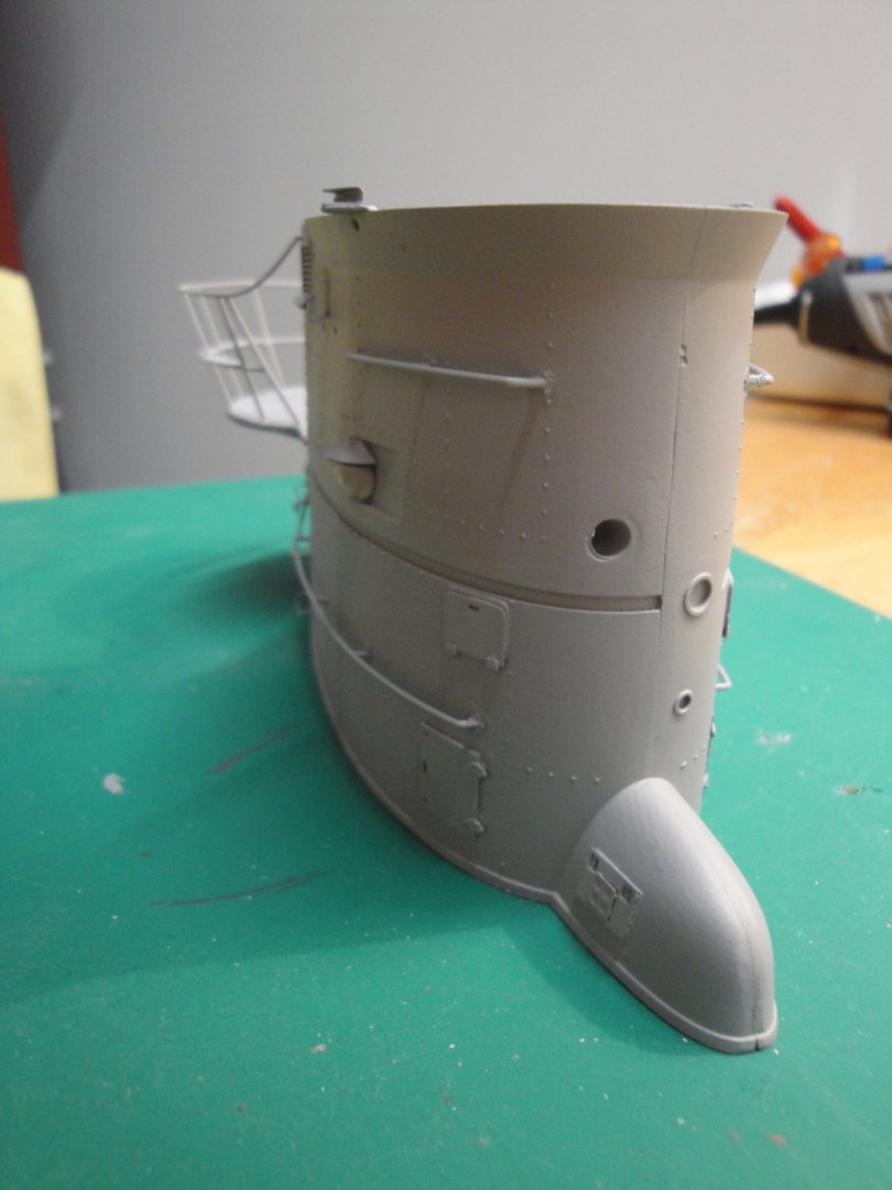
Some progress on the conning tower. There is still plenty to do with the periscope masts and their bases. As you can see, RCSubz offers a lot of small parts to improve the Trumpeter model: After a coat of automotive primer: At the top of the sail, I added some railings for the crew. This part is missing from both Trumpeter and RCSubz, but is clearly visible on some of the pictures: I feel better about the hatches. It is not as perfect as the prototype but a lot better with the primer. Hopefully, the final paint coat will hide them even more. The compass casing and the front of the sail will need some putty. That's all for today, folks. Yves
- 760 replies
-
- 17
-
-
Very true. I was doing a quick calculation recently and I came close to the same amount.... Yves
-
So, I went back to some of the hatches, removed them and sanded some more. I think the result looks better. One side of the sail is finished and has been primed with automotive primer. The rungs and handrails were a nightmare to put together, due to the size of these tiny parts. The deck is now glued to the finished side. I will work on the other side and will install the navigation lights with micro LEDs. A test fit on the main deck reveals a perfect alignment and position of the sail, on the wart. I still have to add a lot of details on that deck and conning tower. Yves
- 760 replies
-
- 18
-
-
Good point Cog, especially, when comparing the model with the real pictures. To make it perfect, you would have to carve into the sails, the thickness of the PE parts. That would be quite a challenge in itself. The Trumpeter kit provides raised panels for the hatches, which is a stupid idea. Instead they should have done a negative/in depth engraving of the hatch panels. I have tried to sand as much as possible of the existing raised hatches before gluing the PE parts. I cannot sand too much or I will end up damaging the nice riveting on the sails. In addition, the PE parts are very thick because they are made in the same sheets than the decks. I simply wished RCSubz had used less thick brass to print these hatches. I am going to try to prime one side and see how it goes. I may have to backtrack, remove all PE hatches and sand more, risking ruining the sails sides. It is not easy due to multiple mistakes compounding: Trumpeter raised panels and too thick RCSubz parts. Yves
-
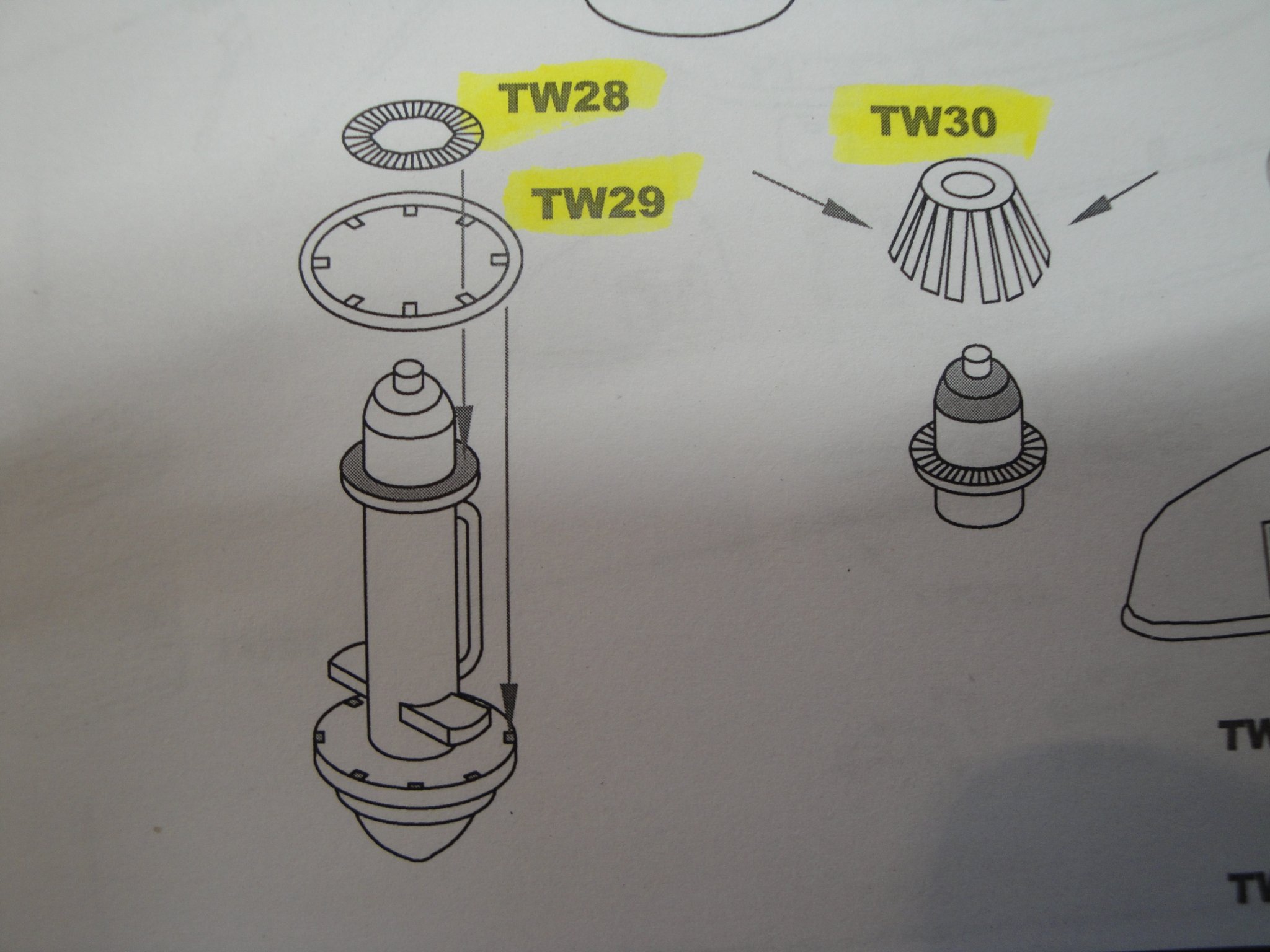
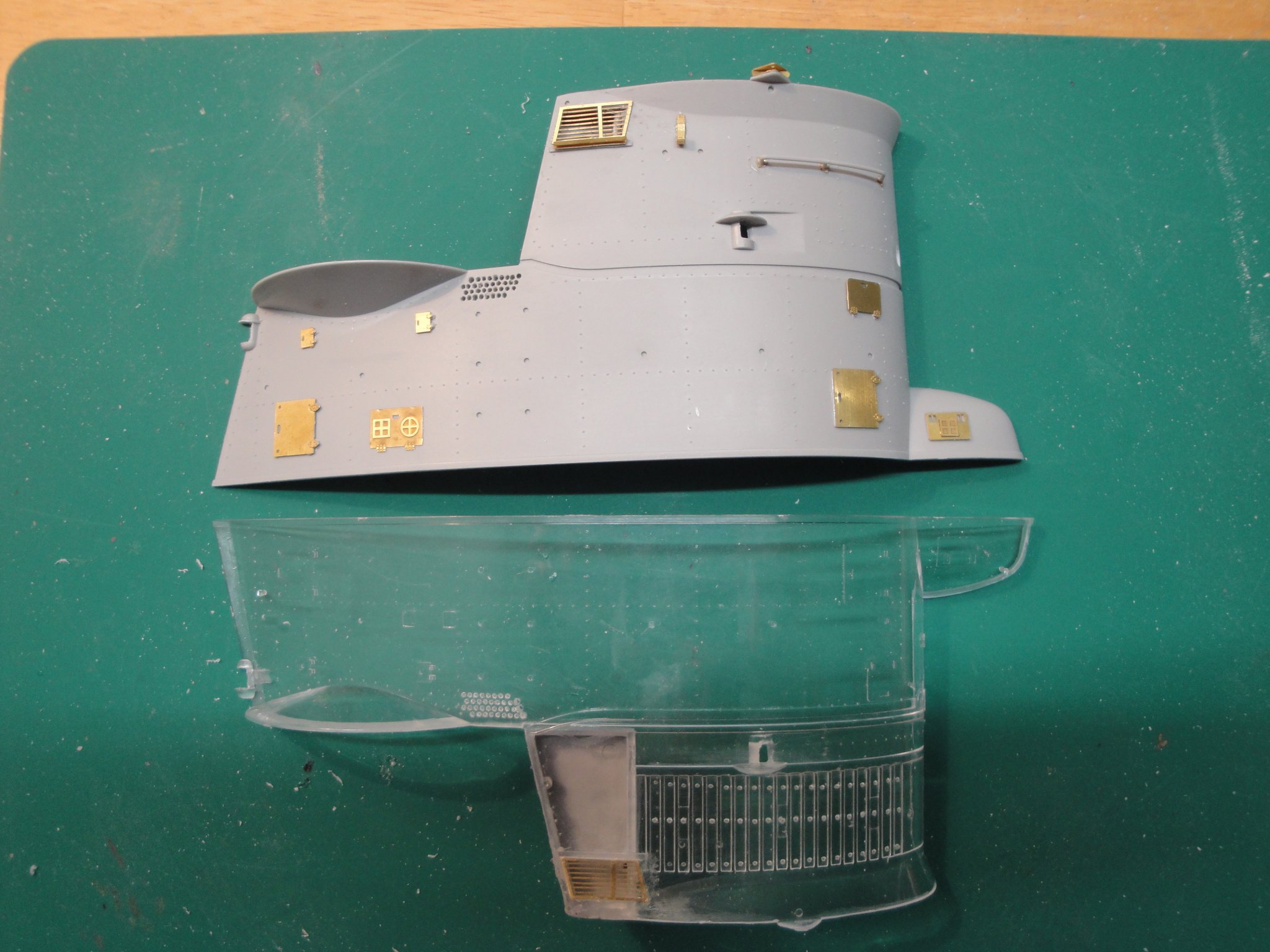
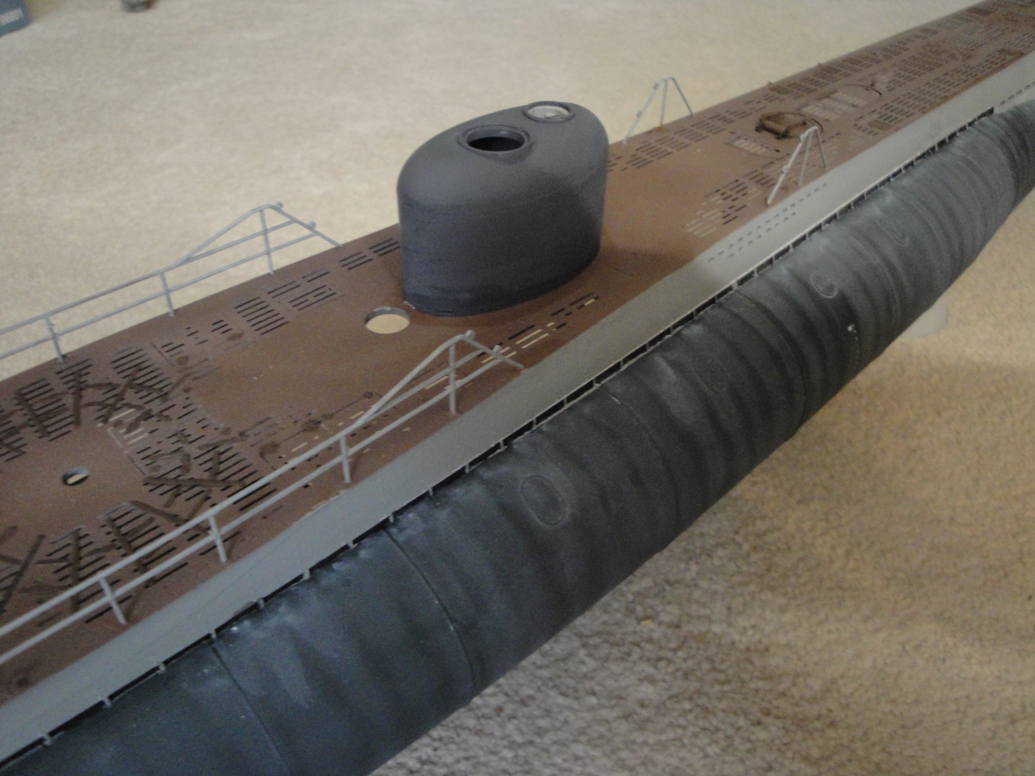
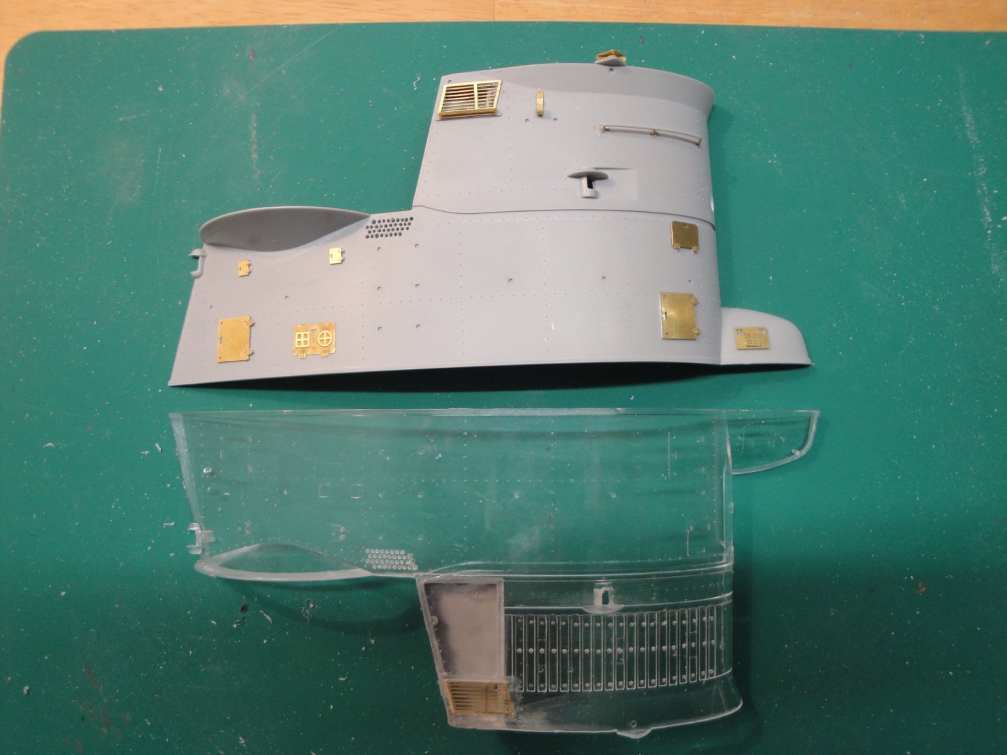
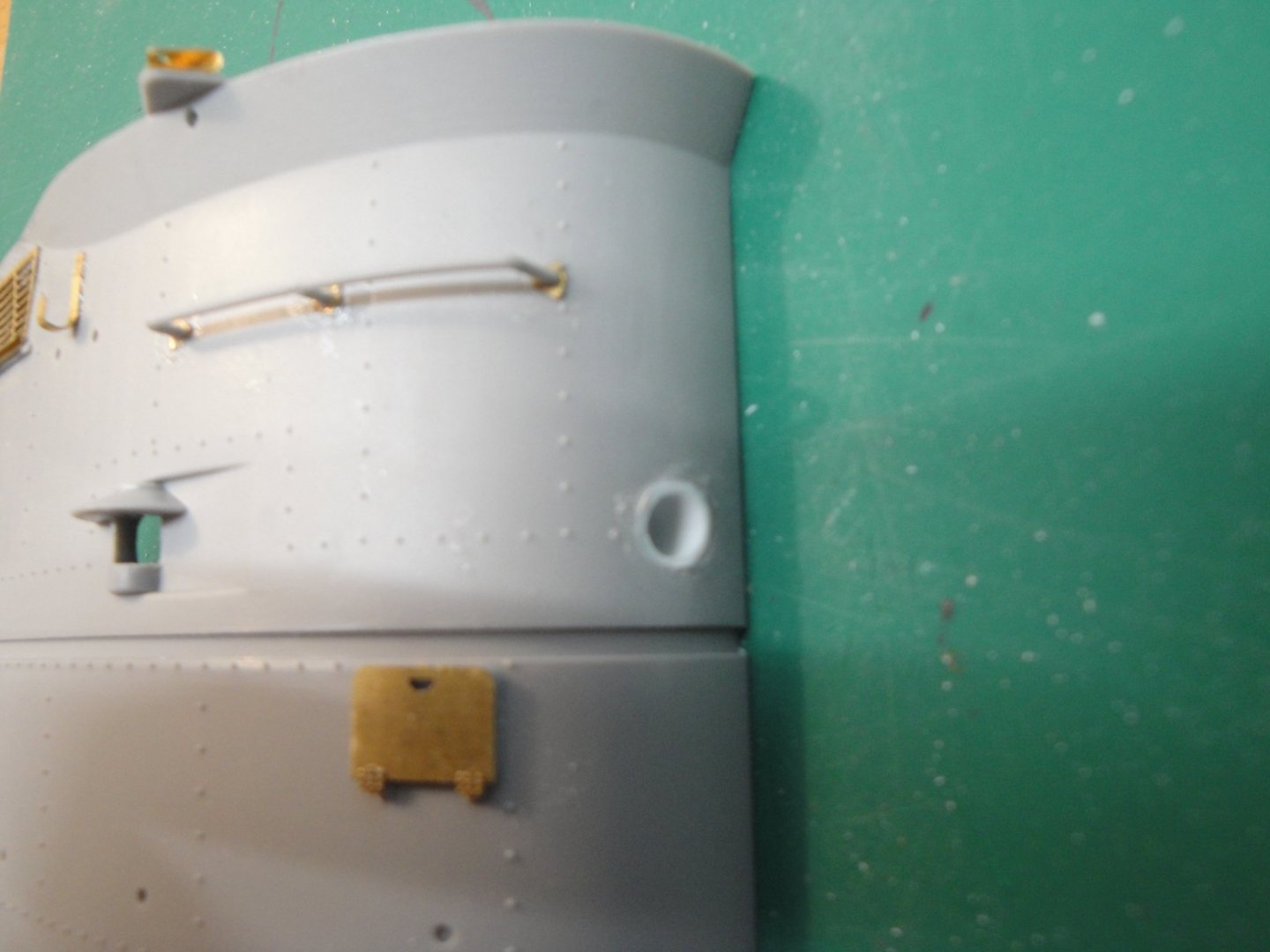
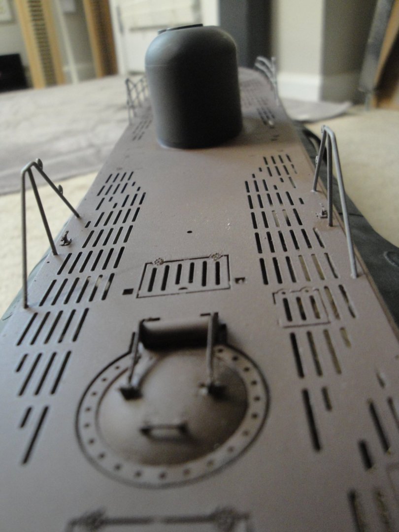
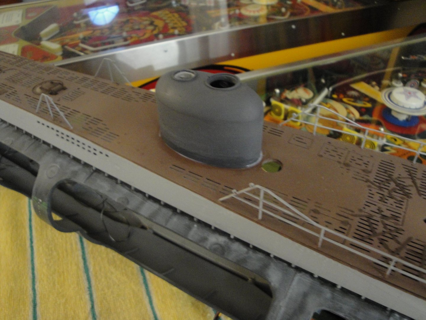
I am now working on the sail sides. The transparent side always offers an additional challenge: harder to see what you are doing and the material reacts differently to the grinding and drilling. It is also more brittle so you have to be extra careful. Same treatment as the opaque side: carving the admission vent, carving the lugs to hold the wood planks inside the sail, carving the navigation light openings. As far as the multiple holes near the greenhouse, I am not able to drill them using my Dremel. The material melts with the heat and the drill becomes bigger, even at very low speed. I will just mark them by hand and fill them with a wash later on. The various decks inside the sail, are being completed: Trumpeter forgot to provide an opening for the antennae connection on the front of the sail. I have added a piece of tube that will contain the ceramic insulator, later on: And finally, a little teaser of what is to come: And more pictures of the wart, that will soon disappear forever: I hope you enjoy. I sure do! Yves


- 760 replies
-
- 20
-
-
Any news about that great development? Are you still planning to release this boat as a kit? Yves
-
Yes, simply lack of time. It is a very complicated compartment and I intend to build it with a lot of details. So, it will wait in the future..... Same for the Control room and the kitchen area. It is more important for me, at this point, to prove the feasibility of that big model with all its electric connections. The great stuff about that Trumpeter kit, is that you can take it at your own pace and build the modules as you wish.... well almost as you want... Yves
-
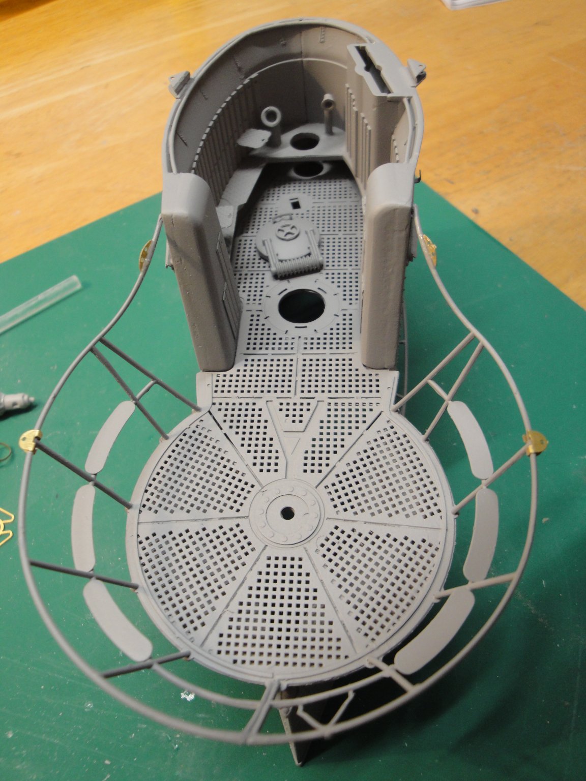
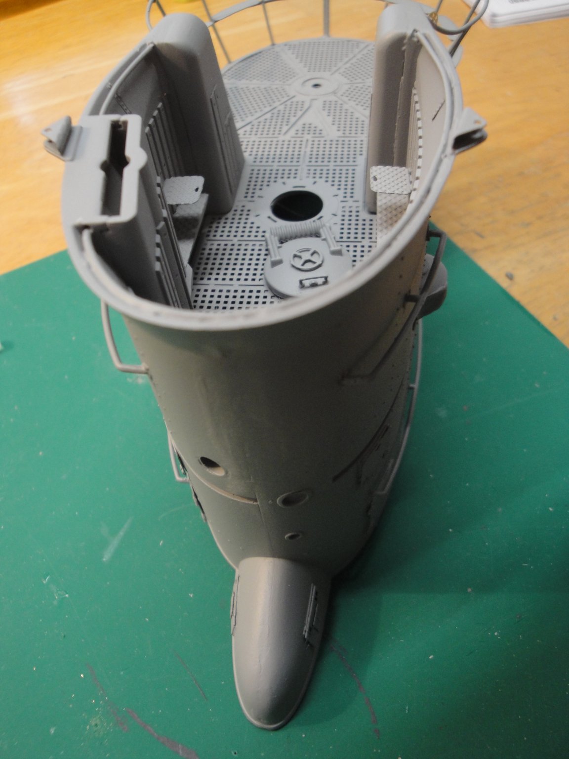
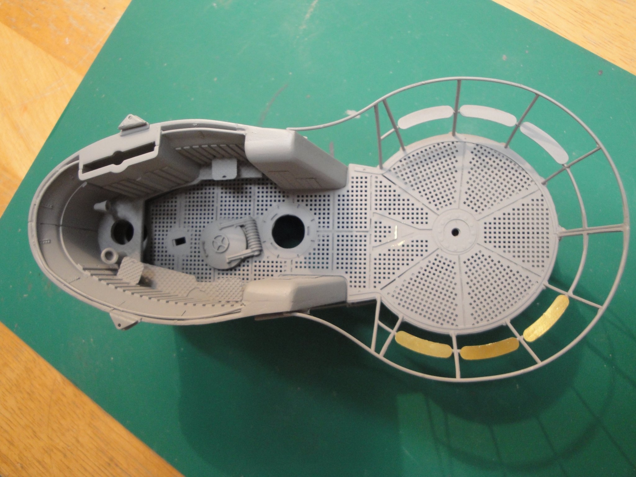
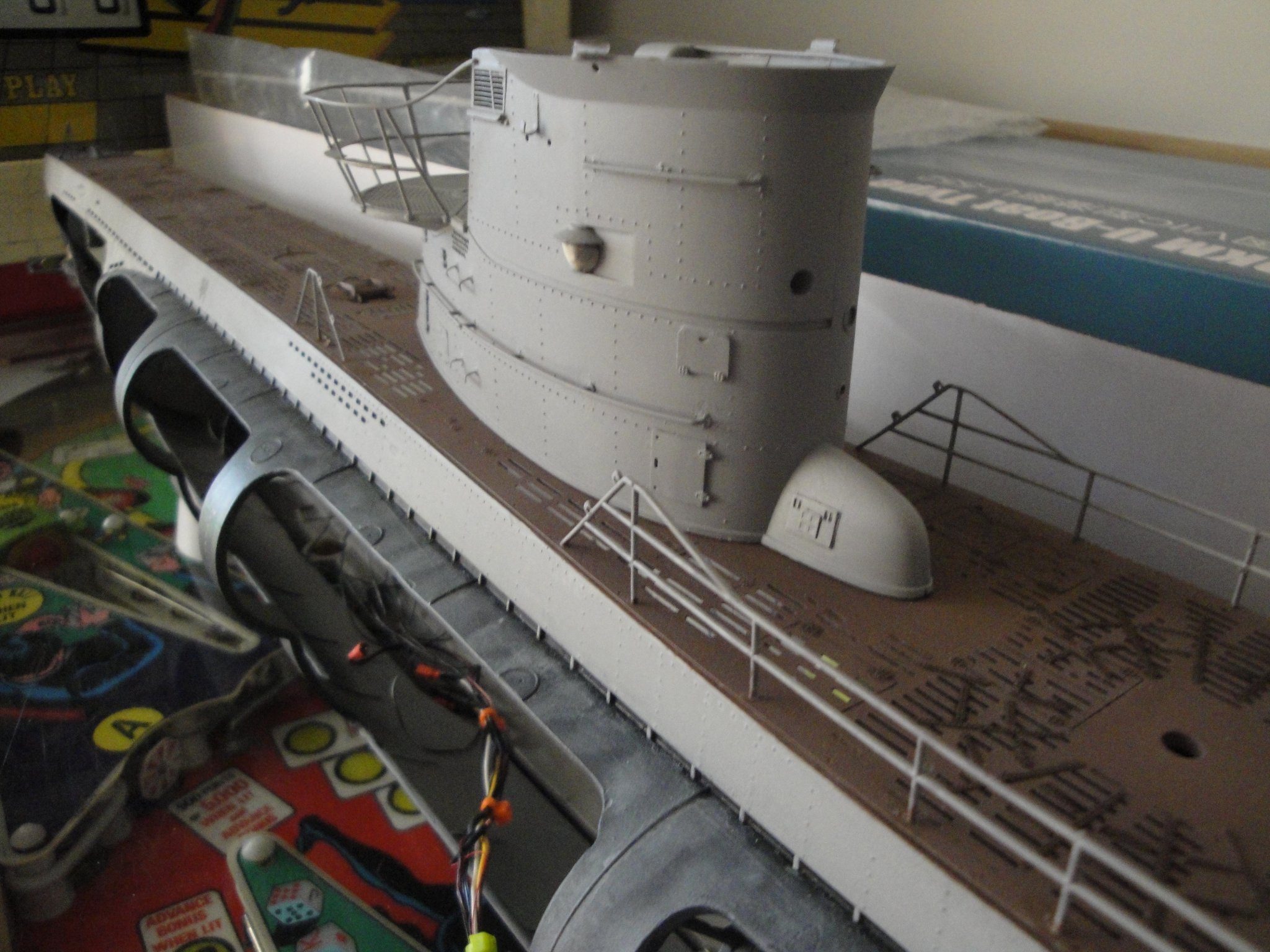
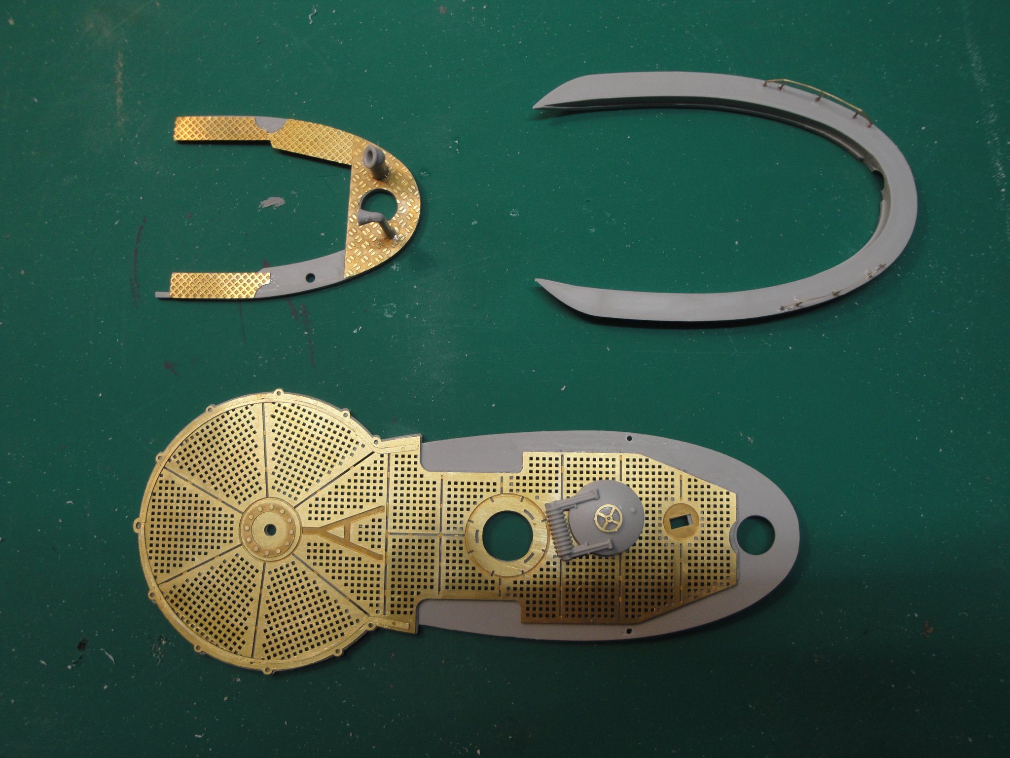
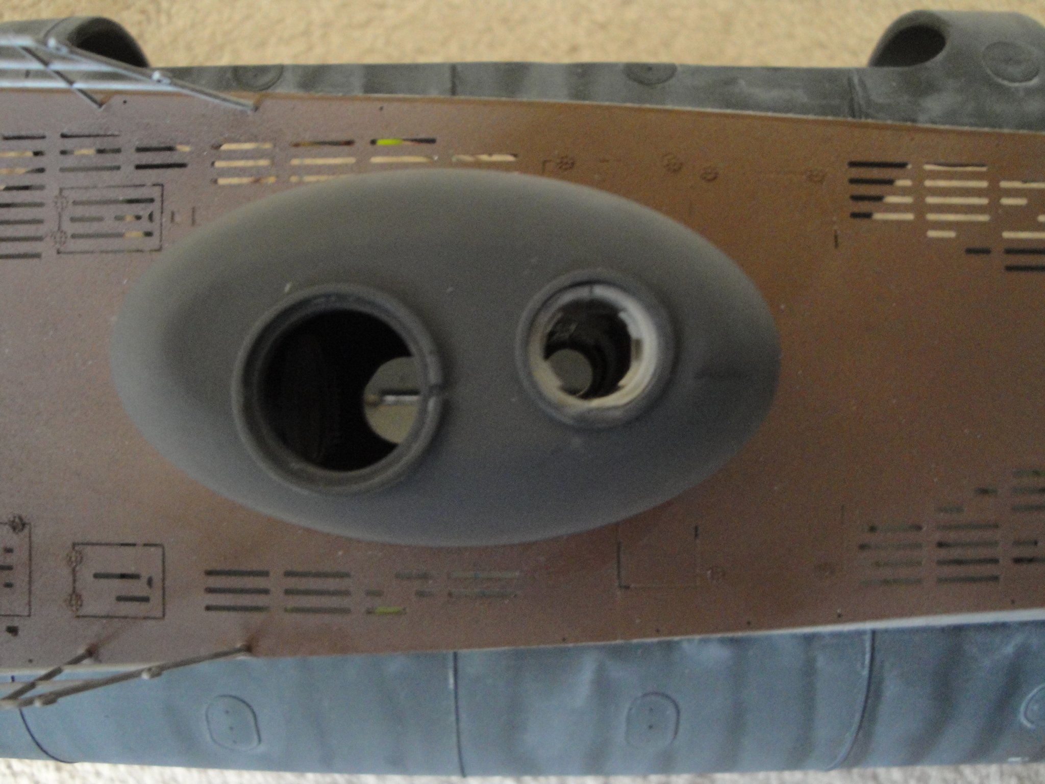
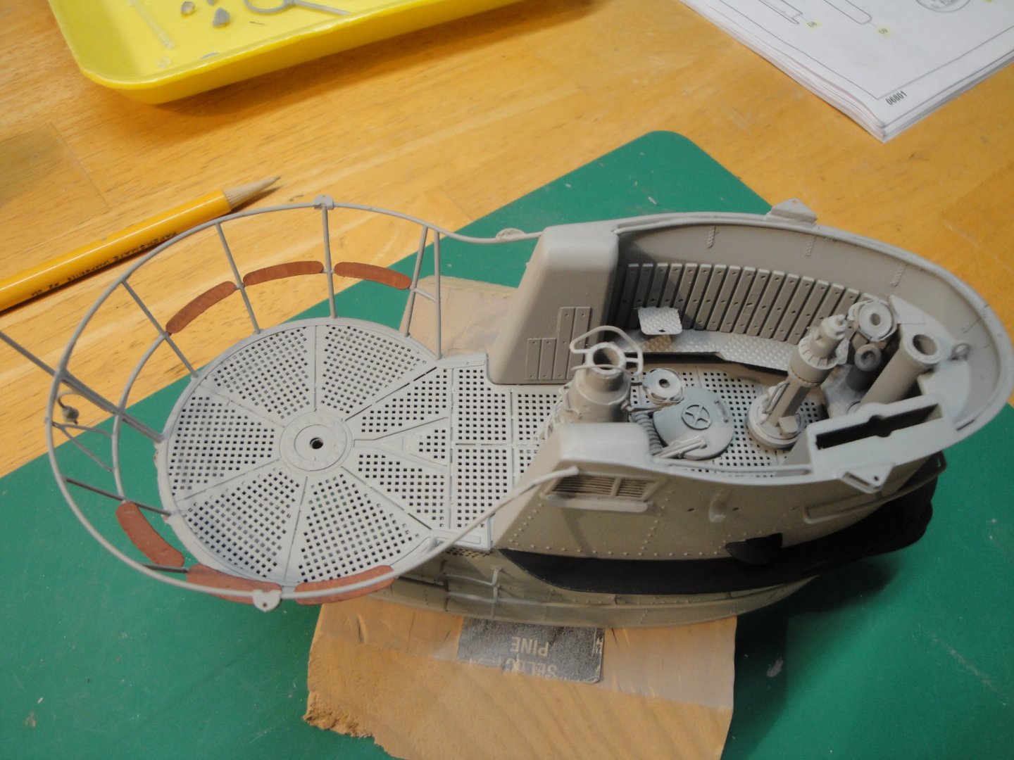
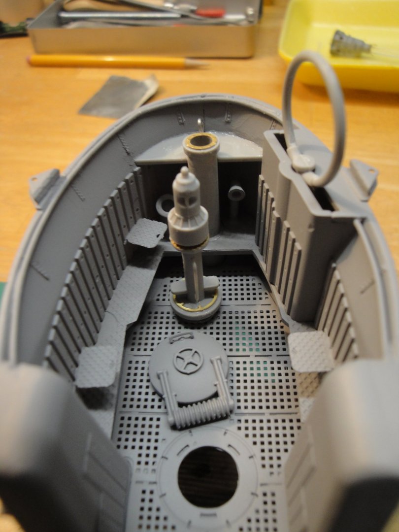
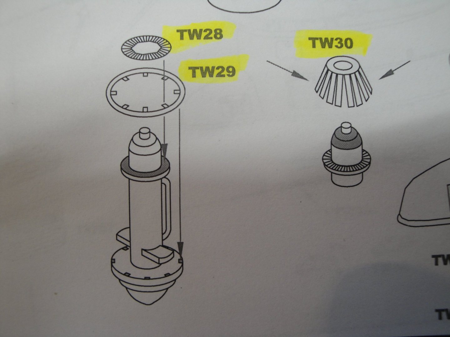
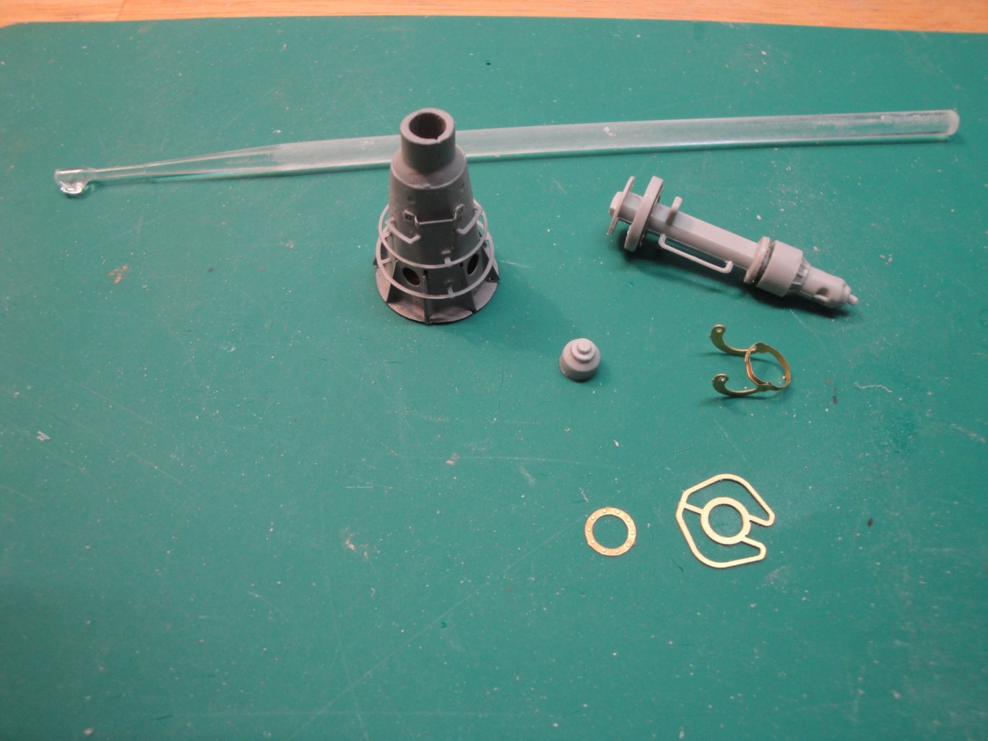
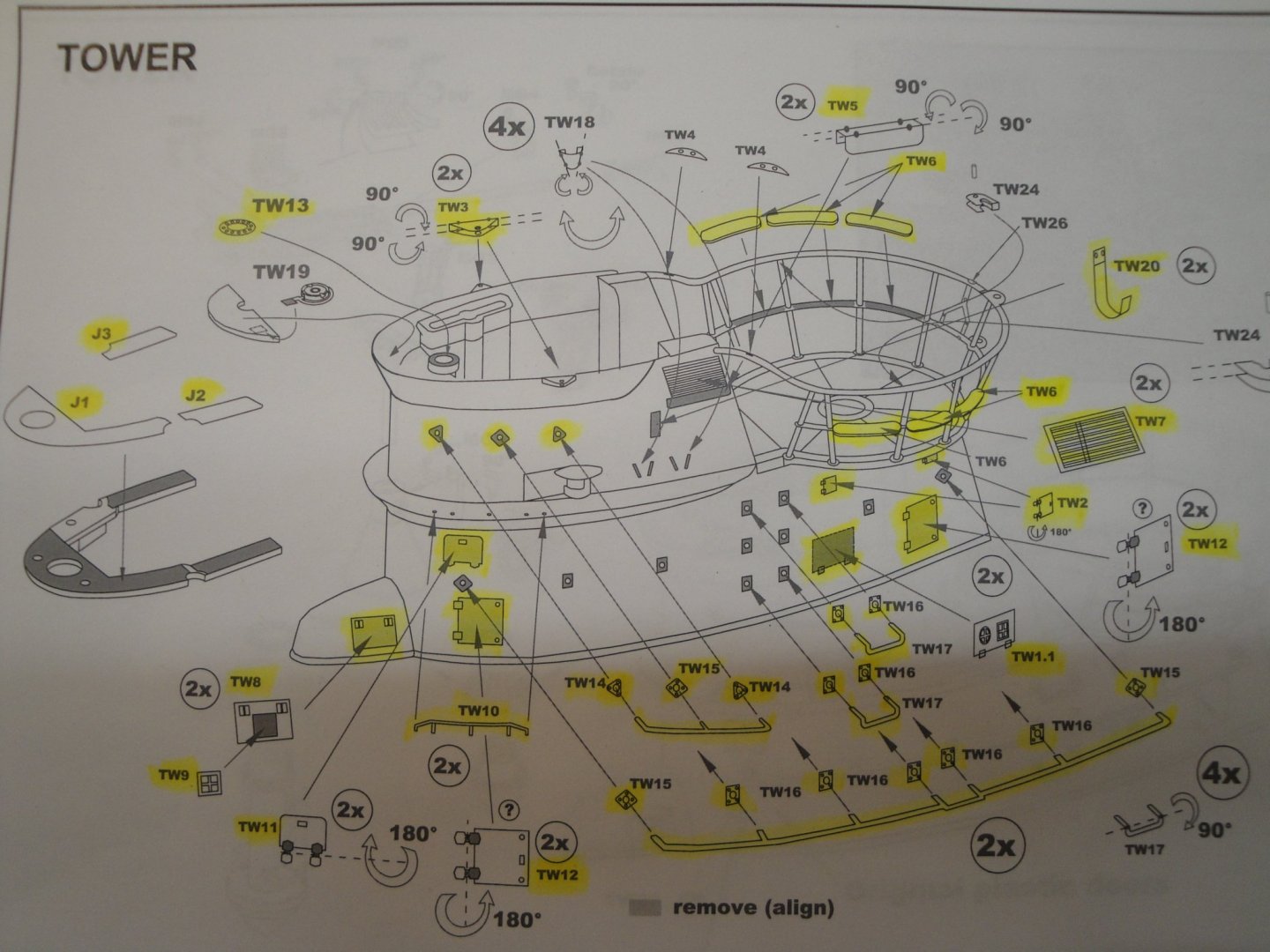
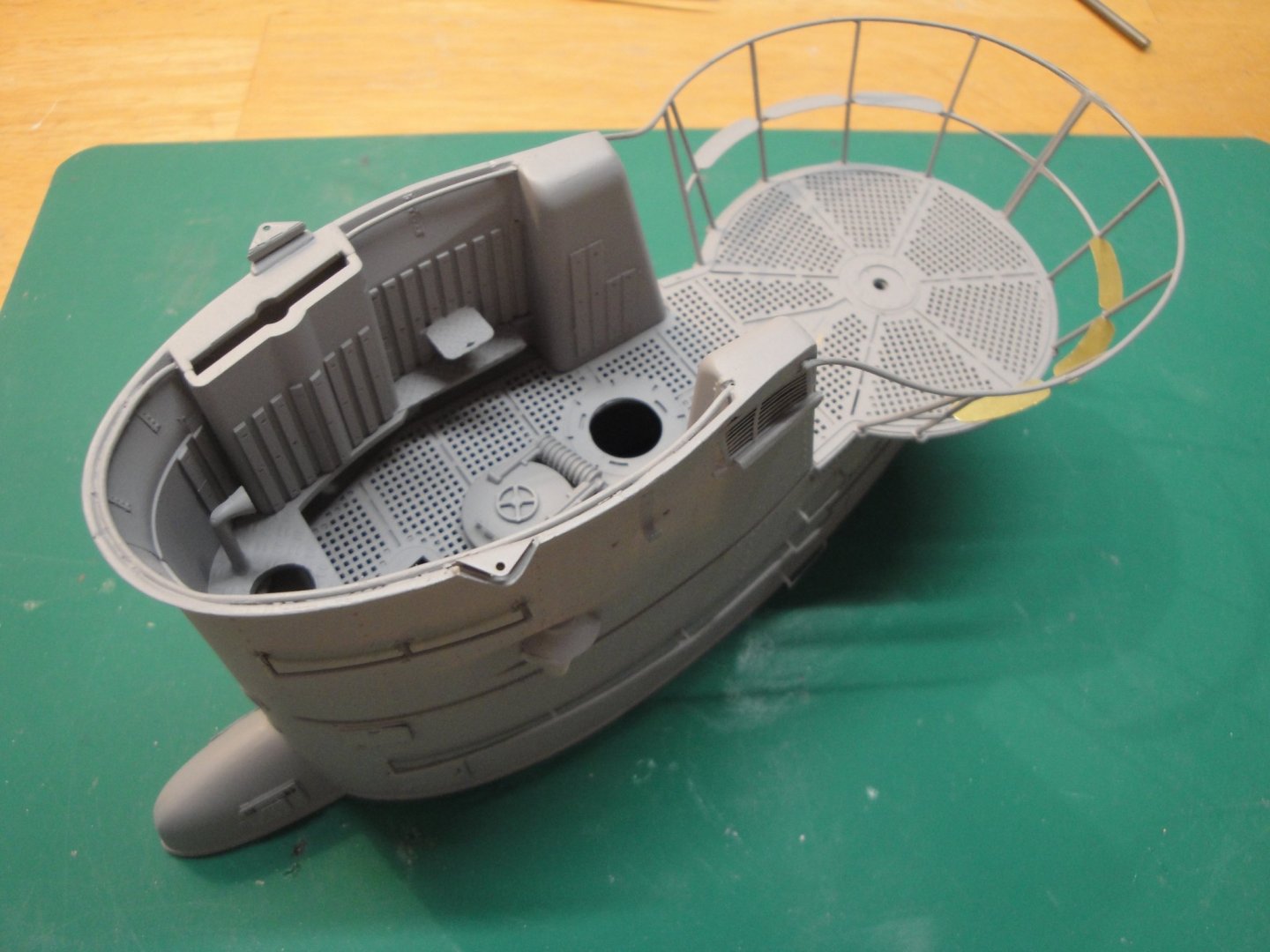
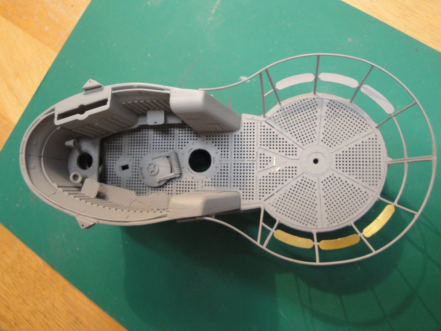
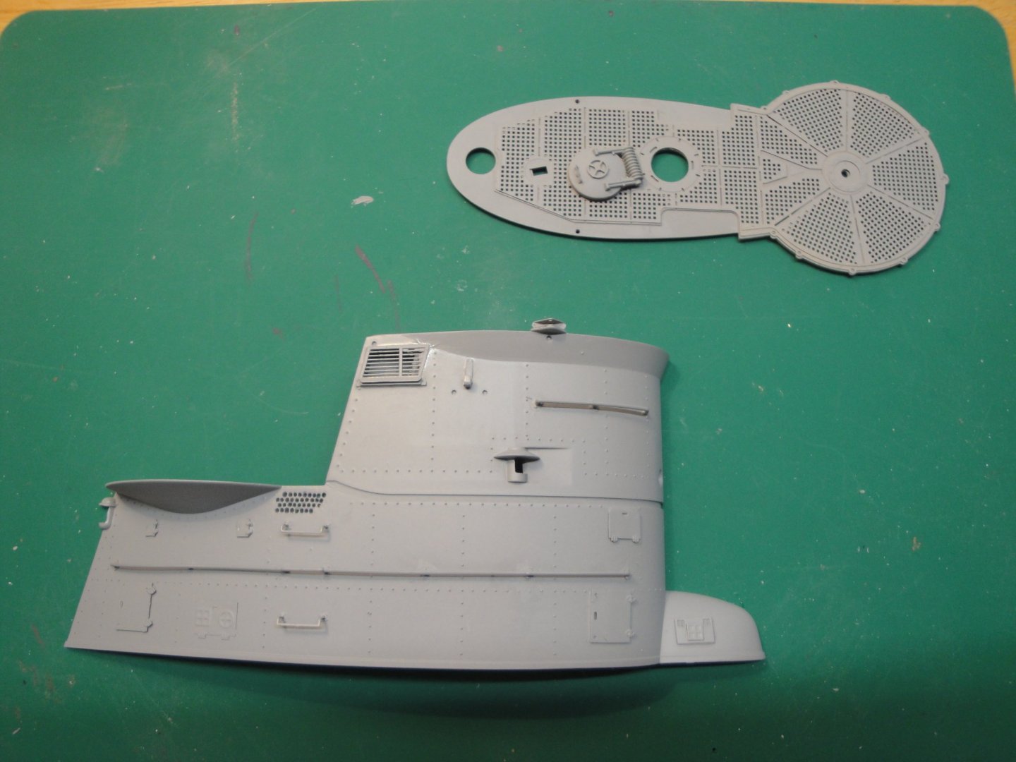
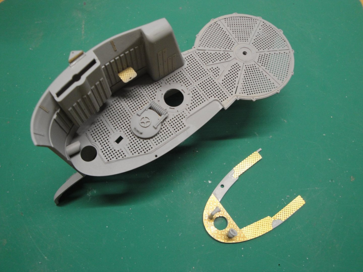
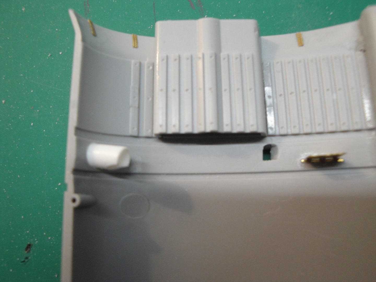
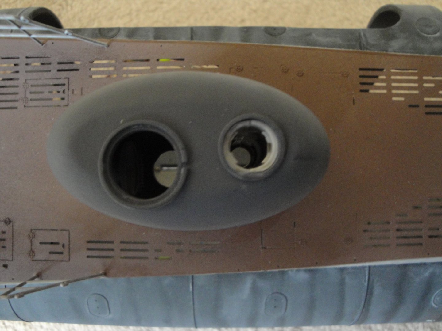
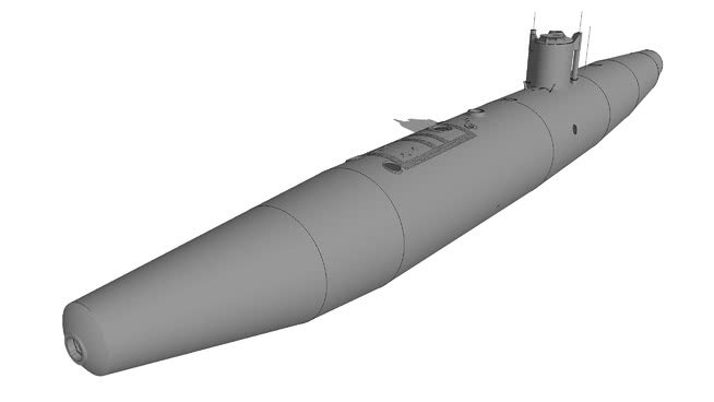
We are now working on the inner hull of the sail. That part of the submarine was built extremely stiff and re-unforced to withstand underwater explosions and air attacks. The inner or pressure hull of a submarine has the shape of a cigar with a big wart on the top. You can also see the large opening just above the Diesel compartment, to allow the insertion of these giant engines (no, they could not pass through the main hatch access 🙂 even through the torpedoes chute 😞 Unfortunately, the inside of the sail will not be visible but I could not resist the pleasure of putting it together with all the provided parts: Here you can see the attack periscope that provided another point of vision for the Kaleunt or officer in charge of launching the torpedoes. That periscope is finally mounted on the deck. It will be used as a guide to position very precisely the inner pressure hull of the sail: Let's not forget the hatch lid: All the above will be of course, completely non-visible, once the lid is placed on the deck: The "wart" is glued with acrylic glue for a very precise and slow positioning. It will provide the correct orientation and height of the sail bridge: In the front is the observation periscope tube. A ladder will be inserted before gluing the sail deck, but will not be visible. That assembly explains quite well, how the U-boot Type VIIc was built. Yves


- 760 replies
-
- 20
-