SJSoane
-
Posts
1,649 -
Joined
-
Last visited
Content Type
Profiles
Forums
Gallery
Events
Everything posted by SJSoane
-
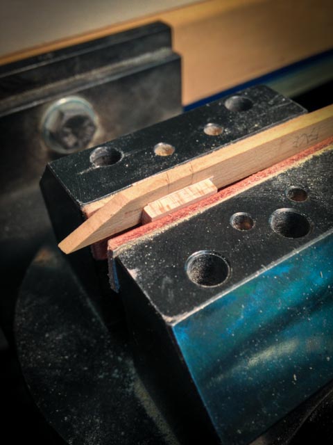
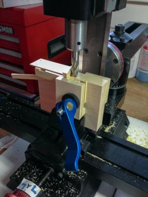
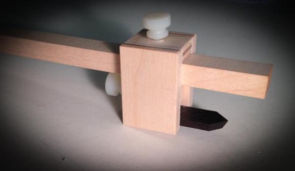
 Hi everyone, I just completed fitting the upper deck clamps, from stem to stern. I was reminded of Remco's quote about treating every piece as if it is a model by itself. The last piece had to hook over the helm port transom, and fair into the forward face of the lower counter planking, while twisting from an acute angle forward, to almost vertical at the counter. Many pleasant hours were spent shaping and fitting these... I can also see that the spirketting right under the wing transom is going to be equally fun, as it curves along that knee while sloping back further up. I had an ah hah moment, which notching the clamp over the helm port transom. To stop the saw cuts at exactly the right depth, I stuck two pieces of wood to either side of the blank with double sided carpet tape. I then clamped this in my vise, and used the wood stops to indicate when to end sawing with the razor saw. I don't know why I did not think of this earlier. It is now in my tool box of techniques. Best wishes, Mark
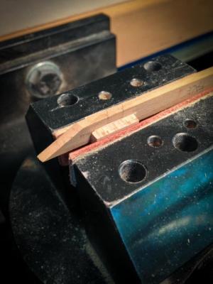

-
Karl, Beautiful scrollwork and carving. What tools did you use for carving the rail once it was cut out? Mark
- 662 replies
-
- 2
-

-
- bonhomme richard
- frigate
- (and 1 more)
-
Hi Michael, Fabulous color choice. Looks terrific. We don't need to be afraid of color, color is our friend.... Mark
-
Ed, Beautiful lines in the stern view. Ahh, ships, works of art.... Are you ripping the knees from the shaped blank on a table saw? Seems like the blade would be high, and a thin piece trapped against the fence on the last parting cut. Mark
-
Treenail detail option?
SJSoane replied to S.Coleman's topic in Building, Framing, Planking and plating a ships hull and deck
Ingenious! -
Thanks, Alan, Grant and Ben. Please feel free to use, and if you improve upon it, pass it on. It is fun to think about the basic geometry of a process, and automate it. Having said that, I have learned from Gaetan, Remco, Ed T, and David Antscherl about the virtues of hand tools. Gaetan convinced me to keep cutting the carlings mortises by hand, and sure enough, I got fairly consistent and accurate with repetition. Perhaps life is most fun with both..... Mark
-
Thanks, Gaetan, these videos are very helpful! Mark
-
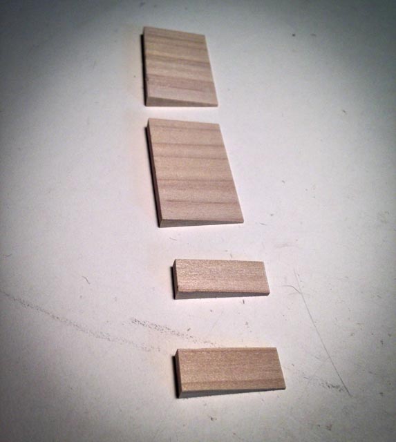
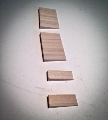
Hi Ed and Michael, I think we have a wedge task force forming here. Here are my first efforts. I threw away the first set because I did not have the grain in the same direction as the wedge, leading I am sure to the thin edges breaking off. Round two, I could not think how to form the wedge on a long piece, from which I could cut individual pieces. So I ended up with the blank big enough for 4, and chiseled and planed the angle. Time consuming and imprecise. Maybe mill the angle? I look forward to brilliant and elegant ways to mass produce wedges from the two of you who are great tool-makers! Mark
-
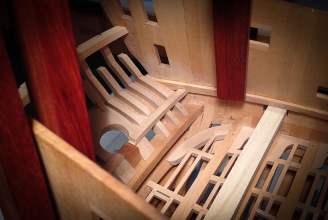
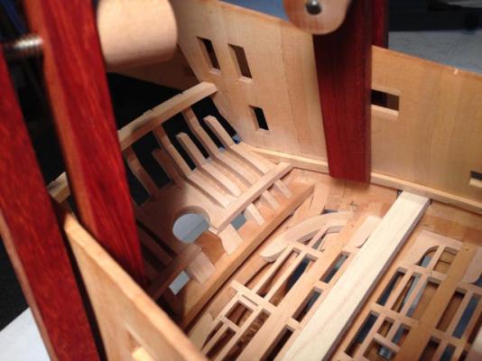
It is like being inside a real ship!
-
Hi Ed, For the first time, I made a batch of small wedges. It was surprisingly fiddly, and I am sure I could have done it more efficiently. I ended up planing the angle on short lengths, and then cutting off individual wedges on the bandsaw. Perhaps a mill setup? But I had my mill set up for scarphs and did not want to break down the settings. I would look forward to your usual great ideas about how to manufacture tools, which includes wedges.... Mark
-
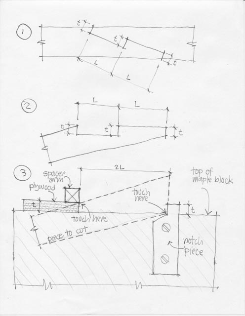
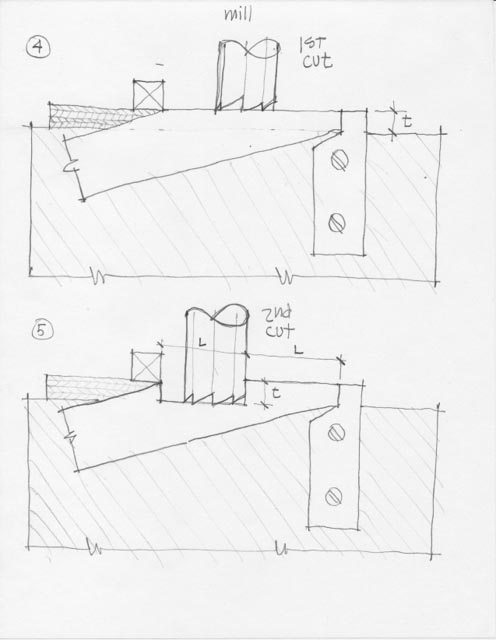
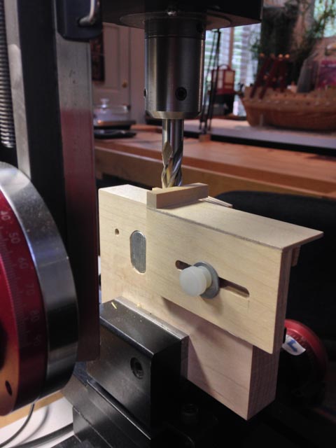
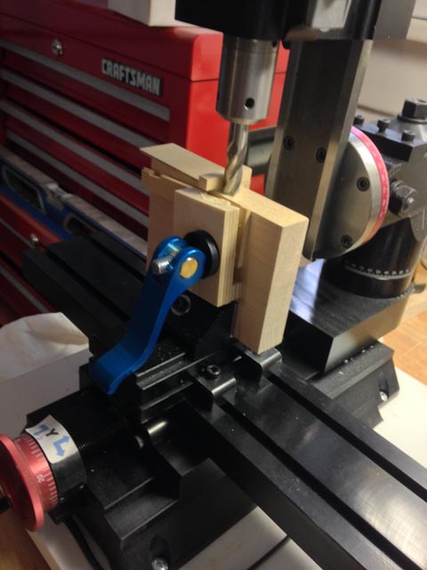
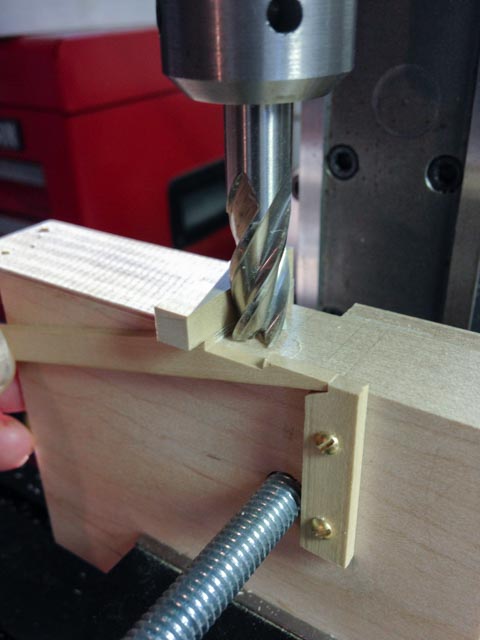
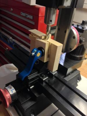
Thanks everyone. Here are more details of the scarph jig. The first drawing, number 1, shows the basic geometry of the scarph. The two long cuts, labeled "L", are equal; and all of the depth cuts are the same and are marked "t". Drawing 2 shows the scarph turned so the angle side will be flat to the mill. Drawing 3 shows the jig, with a spacer arm on a piece of plywood the thickness of "t"; and a notch piece with the same thickness "t" sticking up above the top of the maple block. The piece to be cut is pushed against the notch, and up against the spacer arm. This ensures that all pieces will be in the same location to ensure the same cuts. Also notice that the end of the blank needs to be trimmed to the angle of the scarph before inserting into the jig. I use a sanding disc for this. Drawing 4 shows a mill cutter making the first cut. It is "t" distance above the top of the maple block. In reality, I trim the top of the blank close to this line before putting it in the jig, to save multiple cuts with the mill down to this final cut. Drawing 5 shows the mill cutter making the second cut. Now it is down the distance "t" to the top of the maple block. And it is measured in with the dials of the mill the exact distance "L" from the edge of the notch piece. In my case, the diameter of the cutter was not the full size of "L", and so I needed to move it over a slight distance to complete the second length "L". Using the dials and double checking before cutting ensures that I don't cut into my jig! The photos show the jig with, and without, the clamp. The clamp is simply a T-bolt run through the maple block (you can see the T in the photo from behind), using those cute cam clamps from Rocklers. From behind, you can also see that the plywood spacer on top is glued to a another piece of ply held to the maple block with a nylon screw. This allows me to adjust the spacer arm back and forth to accommodate different lengths of scarphs, or 2 times "L". The whole thing is held in the Sherline milling vise. I hope this helps clarify. If not, let me know and I will draw more diagrams! Best wishes, Mark


-
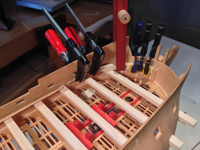
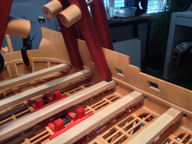
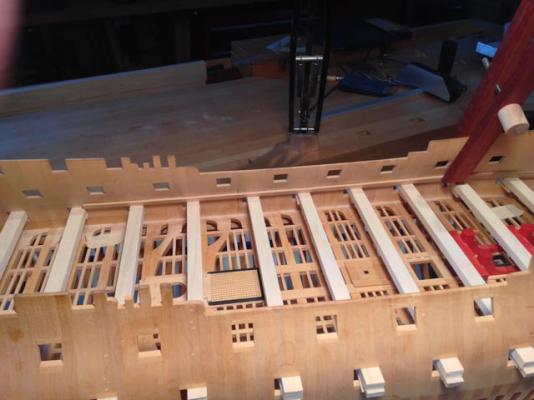
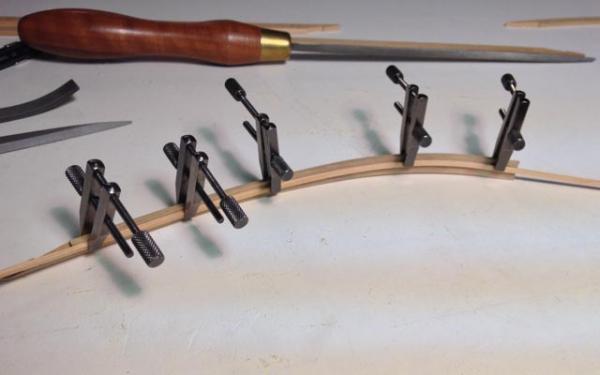
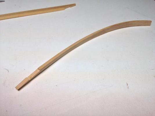
Hi everyone, I got more work done on the upper deck clamps. I am showing first of all my scarph jig, which I haven't used in several years. The first image shows how the stick of wood is pushed into a notch on the right, and up against the projecting arm. This ensures that both pieces are exactly the same angle, no matter what the width (both pieces have to be the same width, of course, to match). The second photo shows the clamp holding it in place. A first cut is taken the thickness of the thin plywood above the maple jig, and then the cutter is lowered to the maple jig to cut the notch. I use the dials to move the cutter exactly the right distance in the X direction. The third photo shows some pieces of poplar run through the gun ports, held firmly up to the top sill by wedges underneath. This allows me to fit the clamps so their lower edges are exactly at the height of the sill (my sills were cut many years ago to include the upper stop in the sill, so strictly speaking, this allows me to align the lower edge of the clamp with the lower surface of the upper sill stop, which I believe is the correct location). With these in place, I was able to plane the lower edge of the clamp until it fit exactly against the poplar pieces, including getting the acute angle right (it changes down the length, so this helped me see what was going on as I trimmed the edge). Then, I could measure up the side at each gunport location to the marked line of the top of the clamp. I transferred this to the clamps and trimmed the top edge accordingly. The fifth photo shows marking the top edge on the foremost piece. This method allowed me to fit these clamps precisely between two very critical locations--the top of the gunports, and the marked line of the top edge. And it helped me accurately shape the acute angle of the top and bottom edges as they twist with the sides. Interestingly, I found that the clamps are not the same width along their length. They are somewhat wider in the bow than in the stern. I double checked my original Admiralty drawings several times; there is no doubt that the line of the upper deck as shown at the sides in the sheer drawing rises gently in relation to the gun deck ports below as it goes forward, causing the clamps in-between to widen towards the bow. Another one of those subtleties of 18th century ship design. I can imagine no reason for this--keeping the decks parallel would have been easier, and it is independent of the sheer which gives the ship its beauty. It is only a couple of inches, but very intentional. The third photo shows a caul I used to bend the foremost clamps in place after boiling for an hour. The caul helped even out the pressure, so the wood did not snap at the location of the first clamp applied. It worked well, although I still get significant spring-back after sitting all night. I have had problems bending this South American boxwood before. Any thoughts from anyone on how long to boil, and how long to let it sit, so I don't get this spring-back? Best wishes, Mark


-
Michael, Yikes, it is big when you see it in relation to furniture. But it looks great! Mark
-
I recently bought the Foredom micro tool, which has a small hand piece with a cord--not a flexible shaft--to a box with a variable speed control box. This also allows plugging in the foot control. It works well. The key issue to consider is having a foot control. In my experience, a Dremel--even with a soft start on switch--revs up too fast to control the small drill bits from wandering from a punched starting hole. The Foredoms allow a very slow, very controlled start with a foot switch, and bits never wander.
-
Very nice, Gaetan. I look forward to hearing the lessons you discover on taking great photos with speedlights, like locations and intensity of the speedlights relative to the camera. Also, lens length. Best wishes, Mark
-
Thanks, everyone, for your comments. Alan, black and white clamps sound like an equally nice idea. Maybe the next set! David, thanks for looking in. I have learned a lot through trial and error and learning from others on this site; I hope some of what I learned can be of use to you as well. Remco and Ed, I aspire to your levels of craftsmanship, so your comments are particularly meaningful. And Ed, thanks again for the diagram in your book on making clamps. It gave me confidence to try. I am starting to think about your more complex right and left hand thread clamps, now these are under my belt. Did you get the taps and dies from Contenti? Mark
-
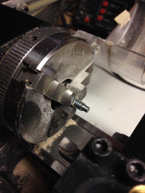
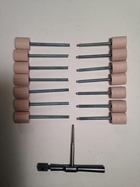
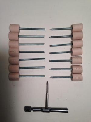
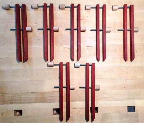
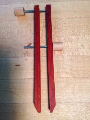
Hi everyone, As I started working on the upper deck clamps, I was quickly reminded that I had no way to clamp the clamps. My hull is solid and offers no places to clamp except through the gunports. And that does not help at the bow. So, inspired by Ed T, I built some long reach clamps. Just for fun, I used up some old padouk left over from my workbench, with maple handles. I was stumped for a bit by how to turn down the end of the threaded rod for a smooth engagement into a blind hole for the top screw. In the end, I just wrapped the rod in masking tape and clamped it in the three jaw chuck. It held firm enough for this light machining, and did not hurt the threads. I will have to work out some specially shaped pads at the end of the clamps, to deal with the angle of the wales and the curve of the bow. But I'll deal with that later, using double sided tape to affix temporary pads. Thanks, Ed, you inspired me to make what I am sure will be very useful tools as I start planking the upper works. Best wishes, Mark

-
Thanks, Michael, it is always fun to think of a simple way to do something repetitive, and in this case I can adjust it to mark several decks! Mark
-
Hi Gaetan, I see you won a Master Level award in the latest edition of the Nautical Research Guild Journal (Vol 59, No 2, p. 140). Congratulations! Mark
- 728 replies
-
- 5
-
-
- le fleuron
- 64 gun
- (and 1 more)
-
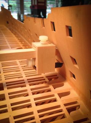
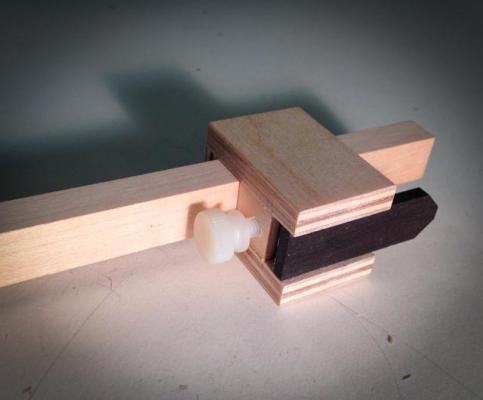
Hi everyone, I finally get to move on to the remaining deck clamps. I made a little marking jig for the tops of the clamps. The head slides back and forth on a beam that sits on the sills of the gun ports. A black pointer slides up and down within the head (the pointer is glued to a short square post captured by the lower knurled screw). So I can set the pointer at the right distance from the sill at each gun port from the drawing, then slide the beam through the head and the two gun ports, and mark with a pencil. Keeps everything symmetrical, and aligned to the gun port sills, which is the important thing. Mark
-
Gaetan, I am speechless. What an amazing setup! Mark
-
Druxey, thank you for the details on painting on paper. I will try that as a way to test out my painting skills anyway, and mock one up on planking to see how it deals with my expansion/contraction problems. Alan, I would highly recommend a visit to Taos, and to Santa Fe relatively nearby. Both very picturesque, very historic as far as North America goes. You will see why artists have been attracted to this area since the 19th century. Regarding the Hahn method, if I had it to do over again, I would construct the hull right side up simply because after a while it was not very fun to look at it upside down for so many years of construction. It has been more interesting to see a little ship on the ways since I turned it upright, rather than a vague wooden shape like a beached whale. Too much deferred gratification for me, building upside down. I still like the stylized Admiralty framing system that I chose, just because I saw so many in the National Maritime Museum in London and long wanted to do one myself. Franklin's book, Navy Board Ship Models, shows some of the interesting details of these types of hulls. Had I seen the work of Ed Tosti or David Antscherl before I started, I might have figured out how to adapt those accurate, fully framed techniques to an Admiralty frame. Maybe someday I will try a little mockup of how that might be done... Best wishes, Mark
-
Ed, I just re-read your books on a vacation, and came away yet again with many good ideas for tools, construction methods, etc. Thanks again for a remarkable resource! Mark
-
Does anyone have experience with TuboCad Mac Delux 2D/3D v7? It is $130 on their website. Mark
-
druxey, Interesting! What kind of paper do you paint on, and how do you affix it afterwards? I was wondering how to paint cherubs upside down, although it sounds equally hard painting them right side up! Mark