SJSoane
-
Posts
1,652 -
Joined
-
Last visited
Content Type
Profiles
Forums
Gallery
Events
Everything posted by SJSoane
-
 Ed, I just re-read your books on a vacation, and came away yet again with many good ideas for tools, construction methods, etc. Thanks again for a remarkable resource! Mark
 -
Does anyone have experience with TuboCad Mac Delux 2D/3D v7? It is $130 on their website. Mark
-
druxey, Interesting! What kind of paper do you paint on, and how do you affix it afterwards? I was wondering how to paint cherubs upside down, although it sounds equally hard painting them right side up! Mark
-
Hi Alan, I was too shy to show the rejected planking; I am keeping it on my bench to remind me of what happens when I rush things (I didn't mark out very carefully the lines of the planking on the framing, and things got wanky after a few strakes--the individual strakes fit well against each other, but did not follow a fair line on the counter). Taos is a small town in northern New Mexico at the southern end of the Rocky Mountains, next to the Taos Pueblo (an ancient Native American town still inhabited, built of mud and straw adobe). Taos became a favorite haunt of artists starting in the late nineteenth century, including Georgia O'Keefe. D.H. Lawrence owned a ranch near there. It is nice to soak in the creative energy of the town, every once in a while--even though it is a long, long way from an ocean or a maritime museum! Best wishes, Mark
-
Hi Ed, It continues to be fascinating comparing this construction to the 18th C British warships. I see the lodging knees are slightly held back from the top surface of the beams, which I assume is to help with avoiding rot. Is this also the case on the upper decks? Mark
-
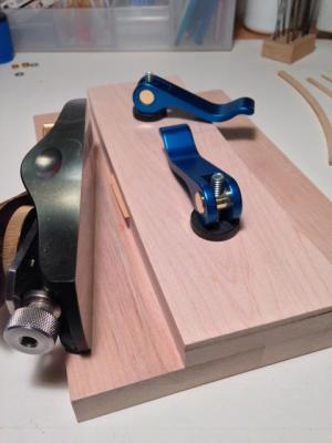
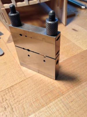
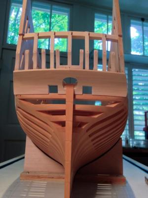
Hi everyone, A long time since the last update. I started planking the lower counter, and after a few strakes were glued in, I decided it wasn't good enough and ripped them off. Then I took a trip to Taos to rethink.... After a new start, I got the lower counter planked. I found two useful tools shown here. The first is the curved shooting board I built a few years ago, which worked well for holding the planks for shaving the convex and concave edges. I used a Silversmith riffler (thanks, Ed, for the lead on this) for the concave edge, starting with a #0 and finishing with a #1. For final fitting, I slipped a piece of graphite paper between the two surfaces, and filed where the graphite showed a high point. I used my block plane for the convex surface, finishing up with a long #1 flat file to fair the curve. The second tool I picked up a few years ago at a jewelry tool supply store. It is a jeweler's miter, which clamps a piece between two jaws at right angle or any other angle chosen. A file is then used to reduce the piece sticking out to flush with the front surface. It keeps a perfectly straight edge, square to the wide surface. I used this to clean up the ends of the planks, for a good tight fit with the next plank. I did not highlight the joints of these planks, because I intend to paint the lower counter with the stage curtain and cherubs shown on the second model of the Bellona. I thought that emphasized joints here would interfere with the painting... Best wishes, Mark


-
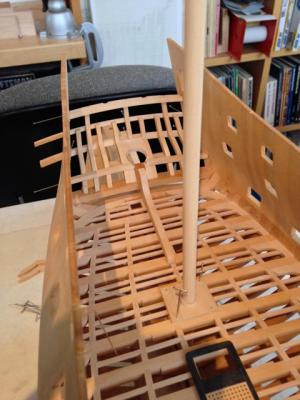
Hi Ed, I just noticed; the diagonal metal straps do not go all the way to the keelson except at the bow. Did they actually stop short as you show, or did you cut them back to allow showing more of the interior? Mark
-
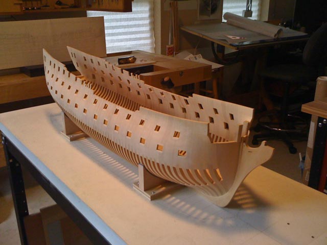
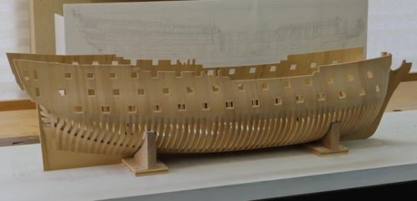
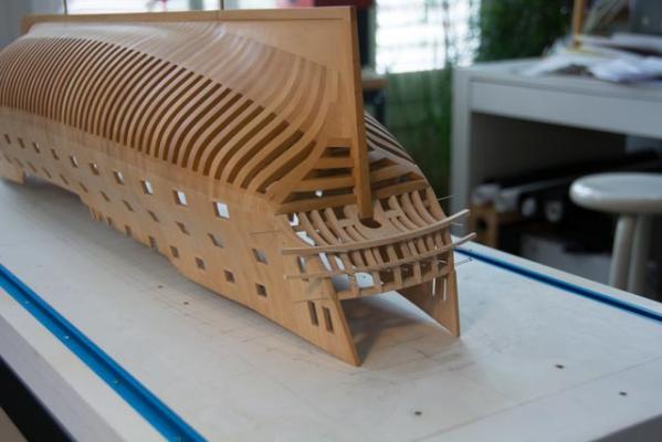
Here are a couple of early photos my my admiralty frame of the Bellona, following ideas in Franklin's book. You can see that I did not highlight the joints between frames. But in the lower hull, which is all that will show after planking the upper hull, the different directions of the wood grain in the separate pieces naturally highlights the parts. Look particularly at the stern and stem deadwood. It is a very pleasing natural contrast. Best wishes, Mark
-
I need advice on a rotary tool
SJSoane replied to jdiven's topic in Modeling tools and Workshop Equipment
I once used Dremels and then switched to Foredom. I have both the big Foredom and the new micro motor. The huge advantages of Foredoms are the foot switch and slow speeds for drilling. You can get the bit located in the center-punched location, and then slowly rev up the motor so it always stays in the center. With the Dremel, even with a slow-start motor, I couldn't control the bit suddenly spinning up and out the center punch hole. It made all the difference to me in accuracy, to have two hands on the motor braced against the model, and a foot on the switch. And slow speeds help, because you need to pull the small bits out of the hole quite regularly to clear the bit. Dremels would load up a bit faster than I could get the bit pulled back out, leading to impacted sawdust in the bit that had to be cleaned out all the time with a pin. I feel in control with the Foredom in a way that I never did with the Dremels. Plus, the Foredoms are high quality, bullet-proof industrial tools that will last a lifetime. You can feel the quality in your hands. i could imagine the eighteenth century model builders using Foredoms....;-) -
Nice start!
-
Gaetan, It is majestic to see the ship next to people. It really shows the size of the project. And what is the scale of the little one in front? Beautiful work. Mark
-
Hi Remco, I have also been worried about staining the wales with Fieblings, and having it wick into the frames below. Is it working well to stain the edges off the ship? Also, can you show a closer view of the stain with mahogany and black 6:1? I had not thought of diluting the black with something. I remember Ed worked for a dark brown rather than pure black on his Naiad. Best wishes, Mark
- 1,215 replies
-
- 1
-

-
- sloop
- kingfisher
- (and 1 more)
-
Thanks, Remco, druxey and Ed, I am really benefiting from your experience here. The first plank above the wing transom on either side of the stern post definitely has a bit of a twist to it, although it yields easily to the pressure of a finger to lie flat. Druxey and Remco, if you were to steam it, and there is no easy way to clamp it to its final shape while drying, would you just hold it in place? Or would you gauge the twist and clamp this to something off the model? And Ed, I am using dressmaker pins (stolen from my wife, she doesn't know this yet) that are too tight in a #74 hole for me to push in by hand, and a slip fit in a #73 hole that would not hold it down. Are you using something to push them into the tighter hole while avoiding them bending? I have little holes in the ends of my fingers while trying this freehand. And Remco, I never thought of the idea of CA and a big clamp...now you have me thinking! ;-) Best wishes, Mark
-
How to sand longer stock?
SJSoane replied to Landlubber Mike's topic in Modeling tools and Workshop Equipment
I have found it helpful to sand in one direction for 10 strokes, the reverse the piece and sand again for 10 strokes. No matter how hard I try to keep things level, inevitably I do favor one hand or side more than another. Switching periodically helps even things out. And also check with digital calipers periodically at each and on each side, to ensure that you are doing everything evenly. You can press a little harder on one end or side to even things up as you go along. Checking often means you only have to adjust a little at a time, rather than dealing with a big taper at the end. Mark -
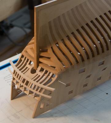
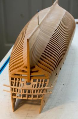
Thanks, Michael, I originally built it upside down Hahn-style, and so saw it this way for many years. It always looked like a good inspiration for a furniture design of some kind. or maybe a sculpture. Well, I spent the entire day starting planking the lower counter, and got two parts not yet installed. But I learned a lot. Those of you who have done this before, did you pin these before gluing? I don't see how to clamp these for gluing, and wonder if pre-pinning will help keep everything in place. Also, I abandoned Goodwin's note that these are 8" width. I tried ruling that out and it looked like way too many small pieces. I went from 12 to 9 strakes, and it looks more convincing. I am closer now to 10 inches at the broadest widths. Mark

-
Thanks, everyone. I just read the David Antsherl primer on planking, which has inspired me to jump into my first real planking project, on the lower counter. I could only find one source for the width of the planks here, in Goodwin's Construction and Fitting of the English Man of War, p. 54. He says the planks for the counters are 2 ½ to 3 ½ inches thick, and 8 inches wide. My drawings from NMM scale at about 2 ½" (thick lines in the drawing allow several interpretations). And unless anyone else has a better source, I'll go with the 8". Oh, fun ahead! Mark
-
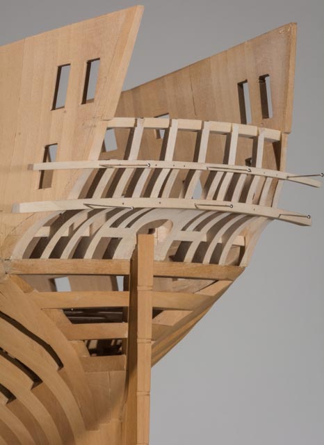
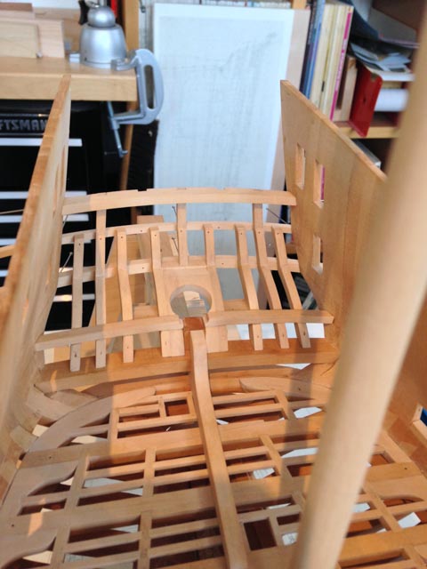
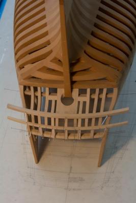
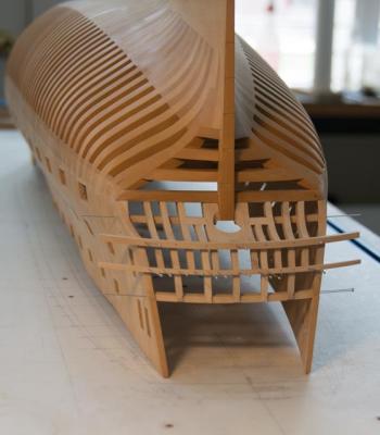
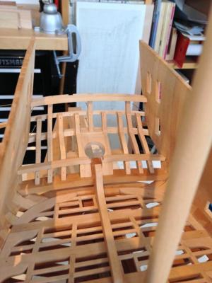
Hi everyone, I haven't seen the Bellona upside down for several years; kind of scary unbolting it from the building board! In all the years of studying, drawing and visualizing the stern, I confess I did not fully appreciate how much the lower counter forms a horizontal shelf. I wonder how many ships boys found a nice place for a nap in the little cubby between the lower counter and the upper deck. I am fairing the lower counter, and hoping to start planking it tomorrow. I'll re-read the great tutorials on planking on the website first... Mark
-
Very nice, Ed. Fascinating to see the differences in technology from the mid-late eighteenth to the mid nineteenth century... And a very nice veneer saw; I couldn't quite read the brand. Mark
-
Thanks, Ed, I just saw your posting in the books section. Very clever, very helpful! Mark
-
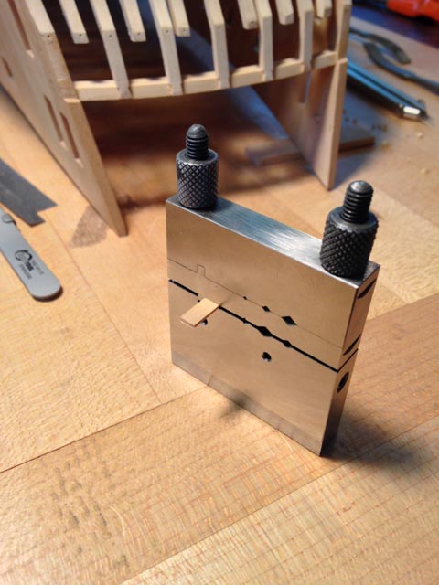
Hi Ed, Very ingenious! Thanks for showing this. I made some chocks a number of years ago (see photo), but I got nervous about leaving them for a long time because the finish might not "weather" as much behind the chocks as the rest of the hull, and I wasn't sure how I would fix it. You have given me an idea of putting some smaller "buttons" on the chocks so they touch less of the hull, and then using your great idea of using the side T-sections to clamp them in place. The other problem with mine is that the hull has to be removed to bolt the chocks in place. Your idea solves that problem. Thanks! Mark

-
Hi Remco, Beautiful work! I am about to start on the iron strapping for the Bellona, and I will use your photo as an inspiration for what to aim for. Mark
- 1,215 replies
-
- 1
-
-
- sloop
- kingfisher
- (and 1 more)
-
Thank you, everyone, for your encouraging thoughts. Who would ever guess in advance that would take so long, and be so fiddly? Imagine doing that with 2 story tall full size oak timbers... Mark
-
Hi Ed, This is a really dumb question, but I was looking at volume 2 of your book set, and I did not see how you were holding the hull upright on the building table after the rudder was installed. Your distance photos don't show supports at the fore and aft ends, nor supporting chocks underneath. Or did I miss seeing a photo? And since you were regularly turning in upside down, did you have a foolproof way of putting it upright and guaranteeing it was level athwartships, or did you need to re-level every time you flipped it? You continue to be my guide.... Best wishes, Mark
-
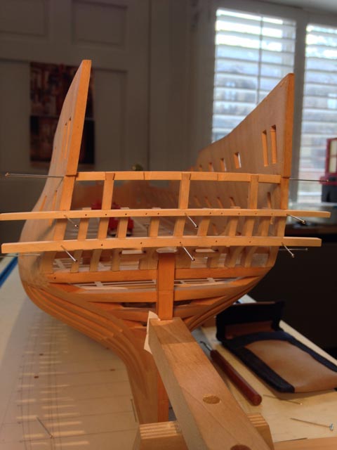
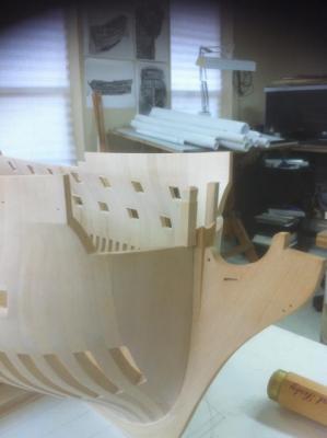
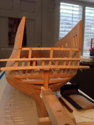
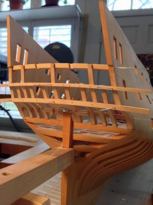
Hi everyone, Big event today. I started on the stern before Christmas, and today I finally glued everything except the upper and lower counter moldings and the two vertical counter timbers above the gun port cills. The moldings need profiles shaped before gluing, and the remaining counter timbers need a little more fitting. It is all looking shipshape! Very, very slow progress on this. Good thing I am not doing this for money.... Best wishes, Mark
-
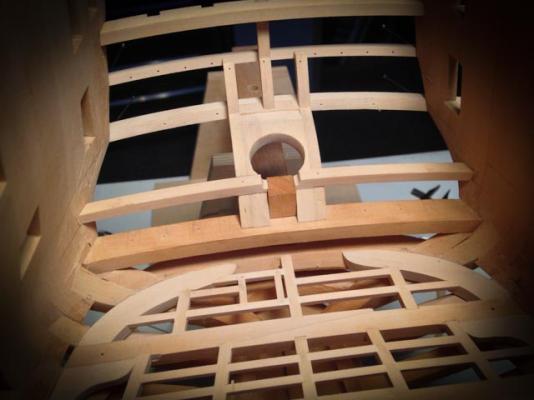
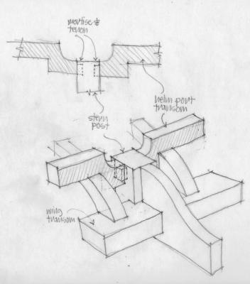
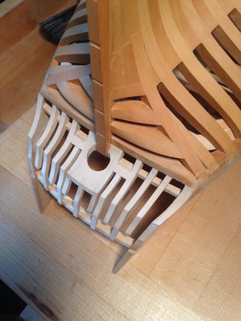
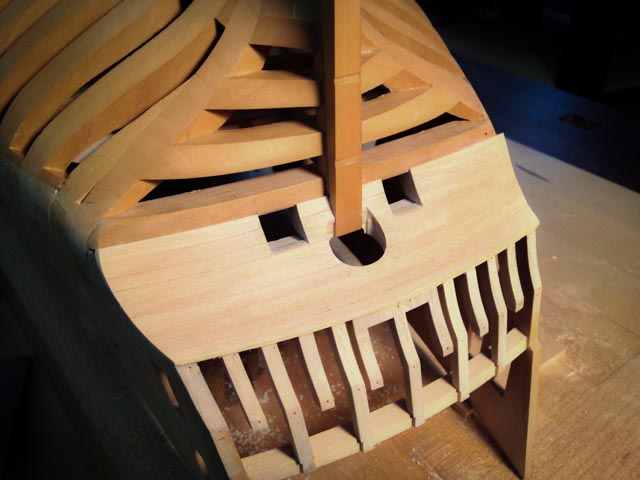
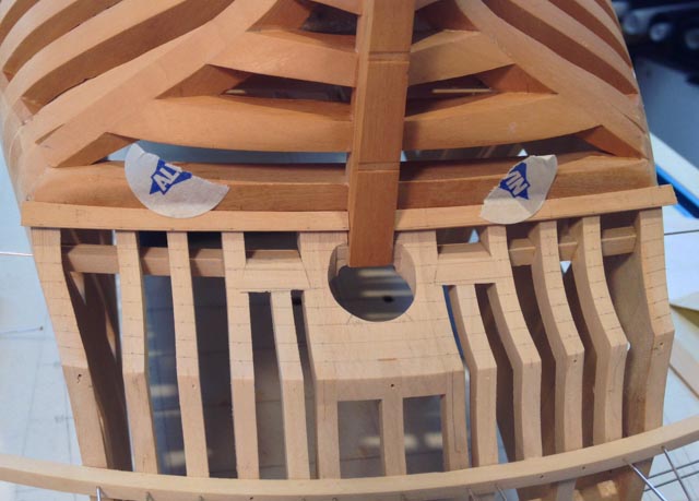
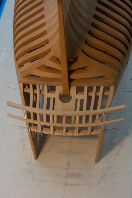
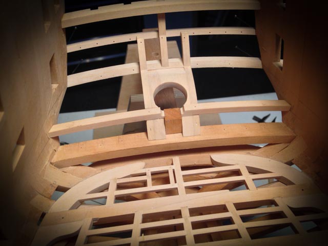
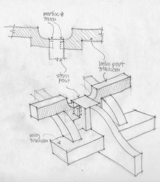
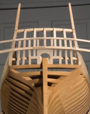
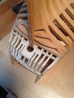
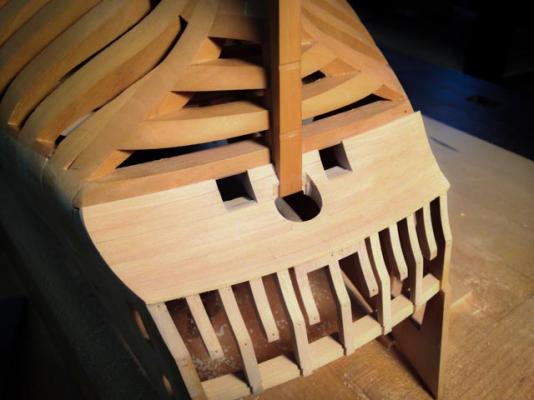
Hi everyone, So I finally figured out--I think--the intersection of the helm port transom and the stern post. After reviewing the photos of the original Bellona model very carefully, the helm port transom clearly intersects the stern post a little aft of center, with a bit of stern post both fore and aft of the helm port transom. So what kind of joint would suit this? I considered a bridle joint intersecting the stern post. But I abandoned this idea, because this would weaken the post at the top by splitting it in two for the helm port transom to pass through. And I began to think that the continuity of the transom all the way across the stern for structural integrity was not necessary anyway. If the transom is split to save the integrity of the post, the two pieces of the transom still bridge on either side between two strong and stable anchoring points, the outer counter timber and the stern post. Furthermore, the upper deck transom (not shown yet in model or drawing) is only a little way above and aft of the helm port transom, and it bridges entirely across the stern giving all the transverse structural integrity needed here. So accepting a split helm port transom, the joint to the stern post is either a dovetail or a mortise and tenon. Maybe I decided on the latter because I did not see how easily I would cut a dovetail in the top or the stern post at this late date. But I prefer to think I decided on the mortise and tenon because it would leave the stern post most structurally integral, and would provide no joint on top of the post for admitting water. This is my story and I am sticking with it.... The drawing shows the intersection without the lower chock for clarity, while the model shows the chocks in place, hiding the lower piece of the helm port transom on either side of the stern post. Best wishes, Mark