HOLIDAY DONATION DRIVE - SUPPORT MSW - DO YOUR PART TO KEEP THIS GREAT FORUM GOING! (89 donations so far out of 49,000 members - C'mon guys!)
×


SJSoane
-
Posts
1,649 -
Joined
-
Last visited
Content Type
Profiles
Forums
Gallery
Events
Everything posted by SJSoane
-
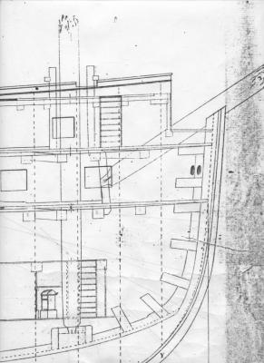
 Hi Siggi, Your drawing confirms it! The dotted line represents the aft face of the frame timbers at the bow, and the rabbet obviously shows the fore face of the frames. Thanks, everyone. Mark
 -
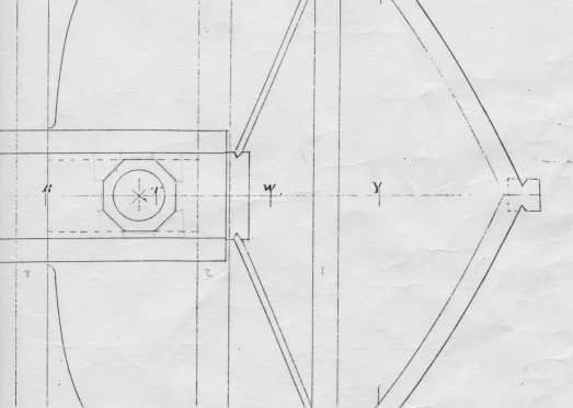
Ah hah! Ed, thanks for pointing me to the plans. The distance in the sheer from the forward perpendicular to the dotted line at the level of the gun deck is exactly the same as the distance in the gun deck plan, to the aft side of the frames (see below). And the rabbet is therefore forward of the fore perpendicular by the thickness of the frames. The dotted line shows up in both the inboard works and the sheer drawing, and is consistent with the plans, so I am assuming now that this was not a mistake. I am assuming from the responses from Ed and druxey that this is not normal drafting for these ships... Ah, the Bellona, I love her even more the quirkier she becomes... Mark
-
I might have figured this out, although I haven't seen this elsewhere. It could be that the dotted line shows the inside face of the frames at the bow, with the forward edge of the decks butting against the frames. The rabbet would therefore be at the forward face of the frames. Except the distance between the dotted line and the rabbet increases in length as it goes higher, whereas the frames should be thinning down; and the dotted line continues past the top of the little bulkhead deck which is also to upper limit of the frames in height. Curiouser and curiouser.... Mark
-
Hi everyone, I am taking a break from the model for while, and putting the Bellona into TurboCad. I have incrementally made adjustments to my original hand drafted drawings over the years, and discrepancies have begun to show up as I move higher up the model. So, I will make a CAD drawing with everything up to date. In redrawing in TurboCad, I discovered something very perplexing about the stem construction that I had never noticed when I originally drafted it. Using TurboCad, I could not make the lines of the rabbet in the stem fair smoothly on the points of the circles that I could pick out in the Admiralty drawing. When I tried to reason this through, I discovered that the original drawings show a dotted line where the rabbet OUGHT to be, i.e., intersecting the fore perpendicular at the fore end of the gun deck. But the rabbet itself has very definitely moved forward of that dotted line. This looks very intentional in the drawing. But it makes no sense. How can the gun deck stop short of the rabbet? There would be a gap between the deck, and the planking housing into the rabbet. Any ideas? Mark
-
Thanks, Mark!
-
Alexandru, Beautiful work as usual. I notice your modified throat plate on the saw, for cutting gratings. Very clever way to attach the spacer! I will try something like that. Mark
-
Looking very nice, Ed. I am learning as I go along the value of marking pieces from other adjacent pieces, rather than marking what it "ought to be" according to the plan. You are way ahead of me in this!
-
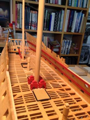
Hi Greg, I agree with you about the white. The second Bellona model uses a lot of what I assume would be ivory for details, and it really jumps out as much brighter in tone than the rest of the model. The HMS Princess Royal in Napier's book shows white deck clamps in the admiral and captain's cabins, and a combination of white and natural wood partitions (red on the weather side, interestingly). I don't like any of the white. I am thinking about a nice wood paneled library in a Georgian house of the time; that is what I imagine the captain would have wanted. So I am going for natural wood. It will keep me to my architectural roots. Now I just have to figure out how to make the matching Georgian cabriole leg table and chairs, for which I am sure Remco will have a solution for me! Mark
-
Thanks Michael, Remco and Ed. It is beginning to look like I will be a one-ship shipwright, at the rate I am going. Your comments help keep me on task! Mark
-
Mark, once druxey started the puns, I couldn't help myself...;-) Bill, thank you for looking in. I once dabbled in furniture making, and learned a great deal from Fine Workworking magazine in seeing how skilled cabinet makers tackled various tasks. I hold your profession in the highest regard. I started my Bellona 25 years ago when I didn't know there were other ship model builders about, and had to learn everything by trial and error with a lot of error, and a handful of old books to give some guidance. But the Model Ship World website now provides a remarkable forum for sharing and learning. I have learned a great deal from the many skilled model shipwrights on this forum. I and others will be happy to help you as you find your way in this amazing field. Mark
-
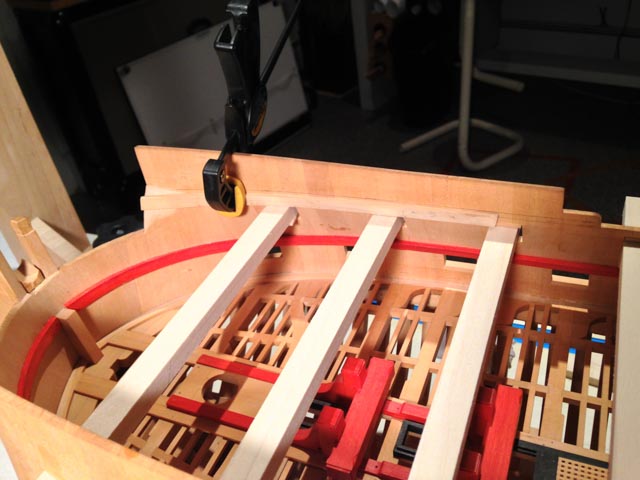
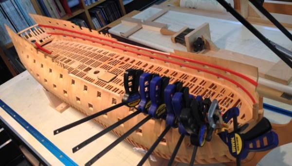
Thanks, druxey, it was also a gripping episode of clamping before the glue began to set. It keeps the pressure on.... Mark
-
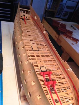
Hi everyone, I finally got the forecastle and quarterdeck clamps, and the waist stringer, installed. I learned a few things. First, the clamps increase in width, therefore increasing the deck heights, the further aft. The officers got certain privileges. Second, the sheer of the moulding at the waist outboard is not the same as the sheer of the clamps and waist stringer inboard. So the waist stringer on its upper surface--where it follows the sheer outboard--is not completely parallel to its lower surface--where it follows the line of the sheer inboard. Subtle, but it shows just how complex and inter-related are all of the lines of the ship. I continue to marvel at the design. I started on the clamps for the roundhouse, but then realized that these will be in the captain's cabin, and I need to think how I am going to color the cabin. The Princess Royal discussed in Rob Napier's book shows white bulkheads in the admiral and captain's cabins. I find white a bit garish, so may consider natural wood panelling. At any rate, the roundhouse clamp will have to wait until I think this through. Mark

-
ROYAL CAROLINE 1749 by Doris - 1:40 - CARD
SJSoane replied to DORIS's topic in - Build logs for subjects built 1501 - 1750
Doris, I will add to the congratulations. Those shrouds have perfect definition of the individual ropes. Did you say what kind of thread you used for making these? Mark- 883 replies
-
- 2
-

-
- royal caroline
- ship of the line
- (and 1 more)
-
Ed, Do I recall correctly on the Naiad that you fitted the lodging and hanging knees to the beams out of the ship? Would that help take care of the contortions in fitting and trimming while the beam is in the way? Having just said that, how would you temporarily fix it to the beam while fitting the assembly? I have done a deck of lodging knees, but have yet to tackle the hanging knees on the next deck. I am watching your progress with close attention! Mark
-
Hi Remco, I am curious, too. What is the diameter of your boxwood treenails? It looks terrific.
-
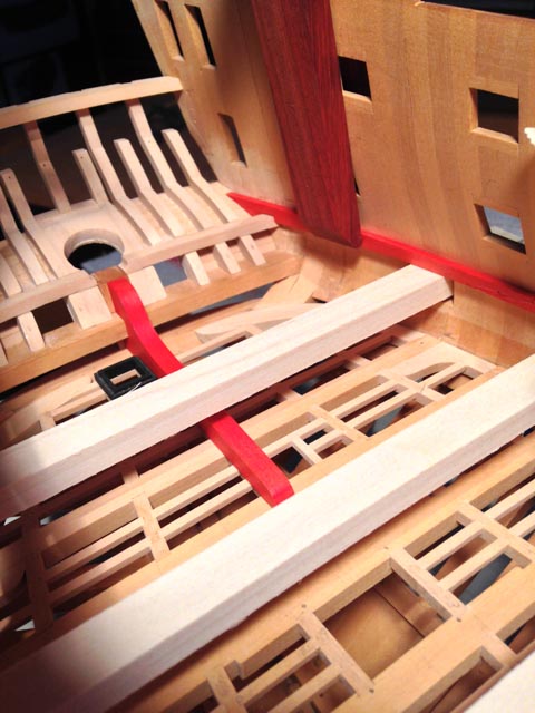
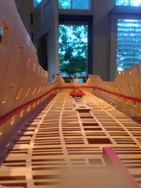
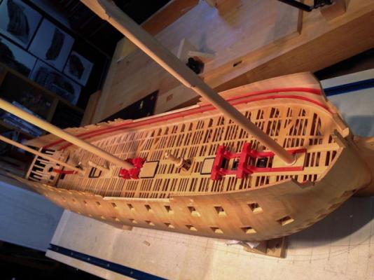
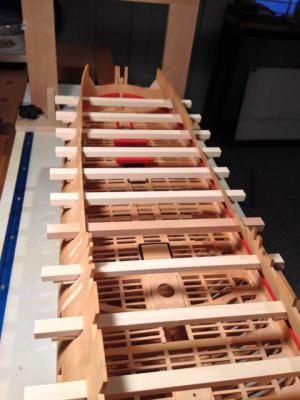
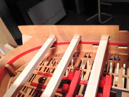
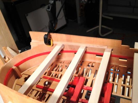
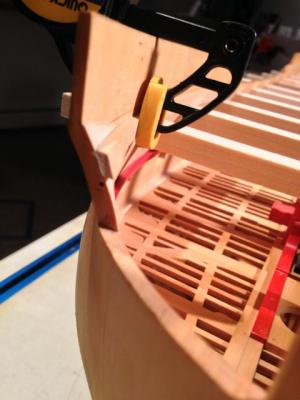
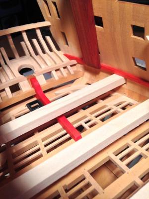
Thank you, druxey, michael, remco, mils, doris and john. Your comments are well appreciated. Work in my "other life" continues to pull me away from the shop, and so progress is all too slow.... Here I am beginning work on the forecastle and quarterdeck clamps, and the stringer in the waist. I always wondered what the clamp did at the fore end of the forecastle, where the sides pull out to form a drop for the anchor. It is a wicked twist from an inward to outward angle as the clamp continues from the waist to the future beakhead bulkhead. I also found that I needed to refine the inner surface where the clamp will lie, now I know its location. You can see some recent filing in this area, which removed the patina that accumulates when my wood is left alone for a long time. That surface probably last saw some sandpaper or a file five years ago or more... Best wishes, Mark
-
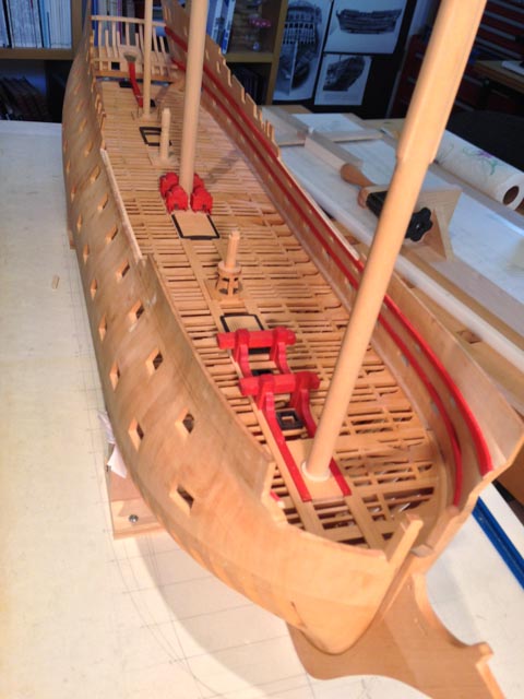
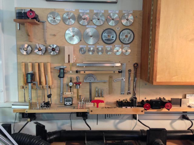
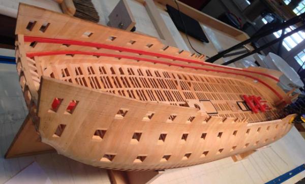
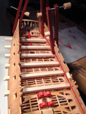
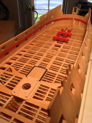
Hi everyone, I finally managed to finish the upper deck clamps, with a side tour to rearrange my wall of tools for the table saw, mill and lathe (it is like cleaning the closets or filing papers when you can't get going on something else). I decided to color the clamps and quickwork red, and spirketting black, like many of the admiralty models I admire. So here is a nice ribbon of red around the hull until more inner works come in. My long clamps came in very handy. I wish I had made more. On the the quarterdeck and forecastle clamps... Mark


-
ROYAL CAROLINE 1749 by Doris - 1:40 - CARD
SJSoane replied to DORIS's topic in - Build logs for subjects built 1501 - 1750
Doris, beautiful work. You are a master! Mark- 883 replies
-
- 1
-
-
- royal caroline
- ship of the line
- (and 1 more)
-
Hi Michael, I am just catching up after a few weeks away. It is looking great! When I read about the amount of ballast in an 18th century ship of the line, It did not seem possible. But now we see it at scale in your project, and it seems more likely! Mark
-
Thanks, Ed, that makes perfect sense.
-
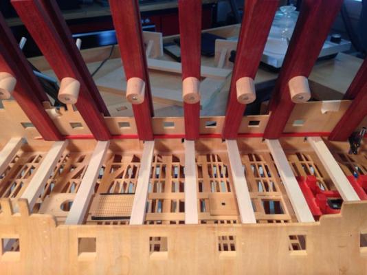
Hi Ed, I have been away, and just caught up with your build. Looking great! Your comment about the pillars between decks reminds me: do you do anything in particular to ensure that they all line up when looked at in a longitudinal direction? I can imagine how slight variations in the drilled holes would let them meander a bit relative to each other. Best wishes, Mark
-
Remco, I had been resisting my wife getting a cat for fear of what will happen in the shop; and now you go and put a permanent cat in your shop. I won't be able to hold out any longer....;-) Mark
- 1,215 replies
-
- 1
-
-
- sloop
- kingfisher
- (and 1 more)
-
Thanks, Michael, druxey, Grant and Mark. Those angled clamps at the upper deck level were definitely one of those projects that seemed straightforward starting into it, only to realize just how complex it really is. These really increase one's appreciation of the original model-makers. It really connects one with the past, to realize that someone made and fitted exactly these same parts 250 years ago.
-
Oh, my! They must have had numerous freight handlers selling little quantities of space, to accommodate all of those diverse goods.