SJSoane
-
Posts
1,655 -
Joined
-
Last visited
Content Type
Profiles
Forums
Gallery
Events
Everything posted by SJSoane
-

Table Saw Blades and other bits and pieces
SJSoane replied to mtaylor's topic in Modeling tools and Workshop Equipment
Nice find on that site, Mark. -
Hi Mark, It looks like you are applying every lesson you learned from version I regarding precision. I look forward to seeing this version develop! Nice to have a set of fine fittings already made and waiting a new home... Mark
-
Remco, you continue to set the standard! Mark
-
ROYAL CAROLINE 1749 by Doris - 1:40 - CARD
SJSoane replied to DORIS's topic in - Build logs for subjects built 1501 - 1750
Hi Doris, I am also interested in how you made the flags. What kind of fabric is it (it looks so realistic at scale), and how did you print these in a laser printer? Best wishes, Mark- 883 replies
-
- 1
-

-
- royal caroline
- ship of the line
- (and 1 more)
-
Hi Sherry, Can you tell us what paint brand and color you used for that wonderful blue, and how you applied it? I apologize if I missed this somewhere earlier in your log. Mark
-
Thanks, Ed, I'll try that.
-
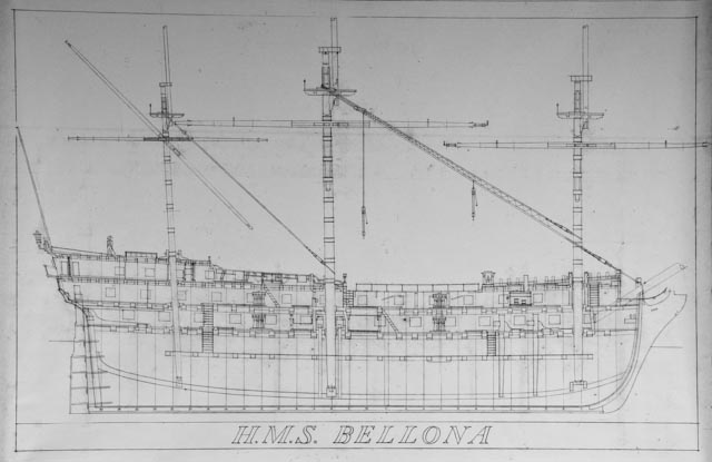
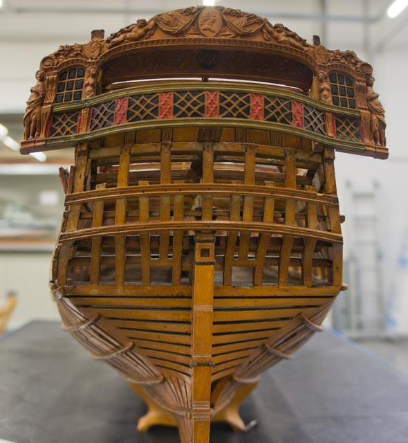
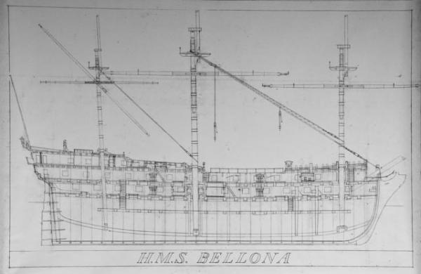
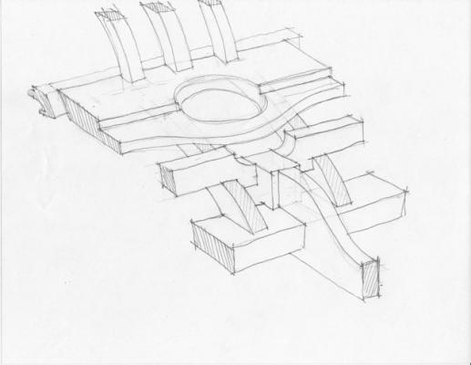
Looking at the images of the Bellona stern again, I see that there is a square transom at the upper deck level, which has to be cut to leave room for the rudder head. Looking at the images pointed out to me by druxey, there are a number of 74s with curved beams around the rudder head. So here is another interpretation, with a curved joining piece fayed to the fore side of the two halves of the square transom that I see in the Bellona photos. I am also showing a smaller transom to serve as a landing for the decking just fore of the vertical pieces. I'll try to build it.... Mark
-
Thanks, druxey, this is very helpful. I looked up the plans you referenced, with a curved beam forward of the rudder head. I also found ZAZ7907 and ZAZ7908 that show the very broad transom. Gary had shown me something similar. The reason I am attracted to this is that the upper surface of the Bellona's upper deck planking hits the fore side of the vertical timbers right at the same level as the inside of the counter knuckle, leaving no landing whatsoever for them unless there is a fairly wide transom to get some thickness for a planking rabbet. The first drawing below shows how tight this is. The second photo shows tantalizingly shadowy details of what is going on inboard of this construction.... Mark

-
Hi Ed, It is looking great. Fun to see construction at the height of the shipbuilding art. I did not have success using a paper cutter for cutting metal. The metal shifted away from the cutting edge. Did you clamp or tape down the sheet of metal while doing this? Mark
-
Very nice, Alexandru!
-
Gaetan, Spectacular! This certainly shows the dramatic difference between French and English design sensibilities. Mark
-
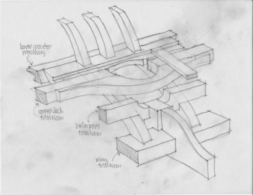
I am working away on the stern construction, and realized that I did not yet understand how the helm port transom and the upper deck transoms fit. Here is a sketch of a possible reconstruction. The helm port drops down to clear the helm, but it also means it runs into the side of the stern post. I had assumed that it would run clear entirely across the stern, but it clearly gets cut in half at the stern post. And the upper deck transom has to accommodate both the hole for the rudder coming through, and also give a landing for the decking. It gets very broad... I'll reflect on this and see if it still makes sense in the cold light of morning. Mark
-
You might look into the classic book, Seamanship in the Age of Sail, by John Harland. It gives a comprehensive account of how the sailing ships worked, all of their maneuvers, different sail settings. It is a fascinating read.
-
Very interesting project. I look forward to seeing more! Mark
- 113 replies
-
- 1
-
-
- heinrich kayser
- steamship
- (and 1 more)
-
Thanks, druxey and Gary, This construction is all the more amazing when you see how big these pieces are in relation to my captain. For those looking very closely, you will see that the center timber is temporarily coming down onto the top of the sternpost. It will be cut away for the rudder hole, but I wanted to anchor its lower end while shaping everything. Mark
-
Gaetan, Oh my, the close-up and the drawing show that it is even more complex than I first realized! What a masterful job. I am glad to hear that you sometimes make a part four or five times. My reject parts box is overflowing... Mark
- 728 replies
-
- 1
-
-
- le fleuron
- 64 gun
- (and 1 more)
-
Hi Gaetan and Robert, Thank you for your kind comments. I debate back and forth about whether to take the time to build a jig, because I am trying to increase my hand tool skills and I have tended to rely too much on jigs rather than on hand-eye coordination. But in this case, there were definitely too many moving parts at the stern to keep everything in place without one. Best wishes, Mark
-
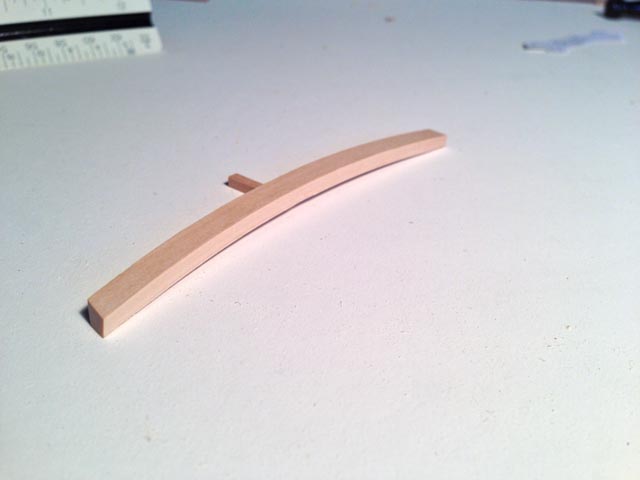
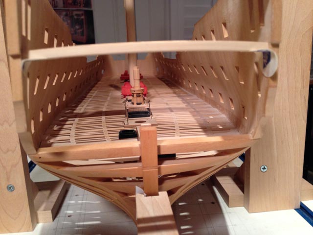
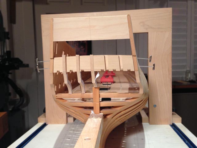
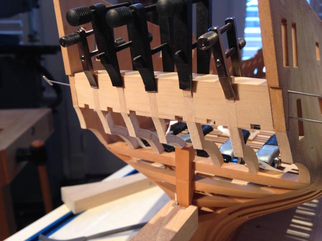
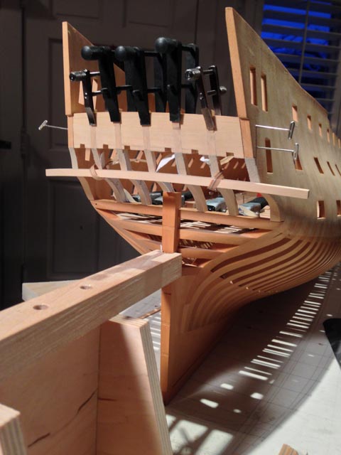
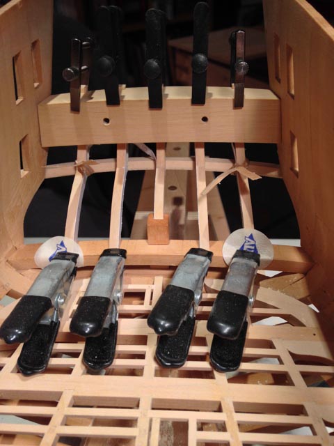
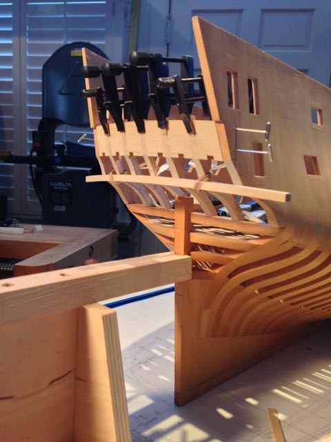
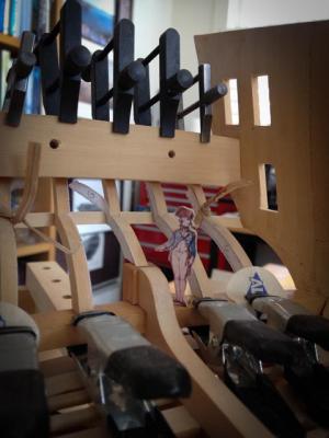
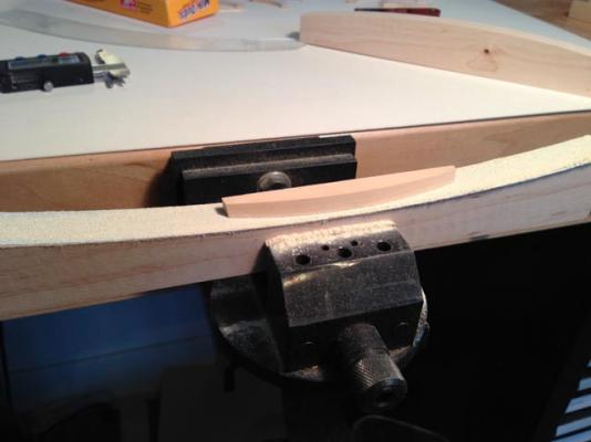
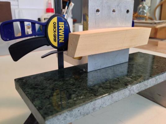
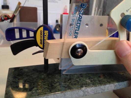
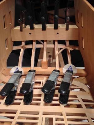
Hi everyone, I have started construction on the stern. The first images show constructing the transom at the quarterdeck into which the vertical timbers will dovetail. When I taped it in place in the third image, I realized that there were too many parts in motion, and I would need a jig to keep it all aligned. So the next images show a jig at the location of the stern lights. The most important thing to keep straight in this construction is the equal spacing of the stern lights. The jig represents the windows themselves, with the correct round up and round aft, and the locations of the vertical timbers. I then cut slots for the timbers into which I could locate them while shaping them. I did not have to work very hard to create the right bevel; I just filed the aft faces flush to the jig. You will also see that I initially mounted the jig on a right angle fixture over a slab of granite. This allowed me to use a flat, parallel surface from which I could construct the radiating lines for the vertical timbers with a drafting triangle. Once I found the correct angle on one side, I could flip the triangle and draw exactly the same angle on the opposite side. That kept everything perfectly symmetrical from the center. I initially tried to do this while the jig was located on this ship itself, and there were too many things in the way. Still lots to do... Mark


-
Gaetan, You are a master of the craft. There are so many curving, flowing lines in the stern, and all fair together beautifully, Can you imagine how the shipwrights originally conceived of those forms? There must have been some trial and error when building the ship itself. Best wishes, Mark
-
Hi Ed, I grew up a thousand miles from an ocean, and knew of ships only through models and photos. I was astounded when I first visited the real sailing ships in the San Francisco maritime museum when I was a teenager, and I could not believe how big they really were. I am still amazed when I put my little captain figure next to pieces of wood or parts of construction in my Bellona model, to see how massively large these ships were. All the more amazing when you think how much was done with hand tools. Your photo and drawing show the same thing. That is a solid wall of wood one story high at the stern, and the stem construction laid flat would be as big as a small sized room in a house. Sobering to think how they did it. Mark
- 3,618 replies
-
- 2
-
-
- young america
- clipper
- (and 1 more)
-
Karl, I just noticed the crucible in which you are melting the pewter. Can you tell us where you found it? I have not seen anything as useful as that. It looks like it has its own heating element. Also, is that a colored spray paint, or just a transparent finish, that you show with the cannon standing vertically? Mark
- 662 replies
-
- 1
-
-
- bonhomme richard
- frigate
- (and 1 more)
-
If this is indeed an early example of something that evolved into another, more practical, form (higher up to avoid bending over), it is a fascinating glimpse into how a tradition evolves over time in a continual quest for greater efficiency and/or beauty.
-
ROYAL CAROLINE 1749 by Doris - 1:40 - CARD
SJSoane replied to DORIS's topic in - Build logs for subjects built 1501 - 1750
Doris, I'll add my congratulations. This is an artistic accomplishment beyond description. Mark- 883 replies
-
- 1
-
-
- royal caroline
- ship of the line
- (and 1 more)
-
Hi Michael, Wouldn't it be great if we could arrange some day a world tour of workshops? It is almost more fun to build and organize the shop than it is to build anything in it.... Mark