SJSoane
-
Posts
1,655 -
Joined
-
Last visited
Content Type
Profiles
Forums
Gallery
Events
Everything posted by SJSoane
-

ROYAL CAROLINE 1749 by Doris - 1:40 - CARD
SJSoane replied to DORIS's topic in - Build logs for subjects built 1501 - 1750
I can't wait to see the entire crew, or at least those above decks.... Beautiful work! Mark- 883 replies
-
- 1
-

-
- royal caroline
- ship of the line
- (and 1 more)
-
Michael, Perfection! Your skills are astounding. Mark
-
Hi Gaetan, I had heard of those Gary Fong light diffusers, but didn't know how it would help with photograph of models. Now I see. Thanks! Mark
-
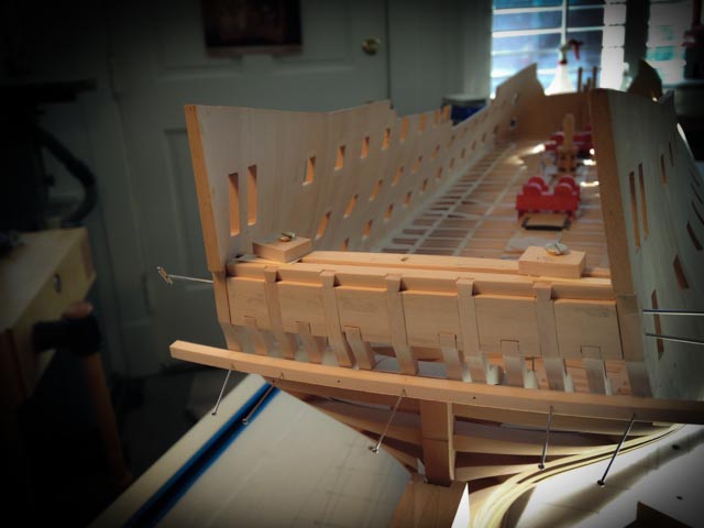
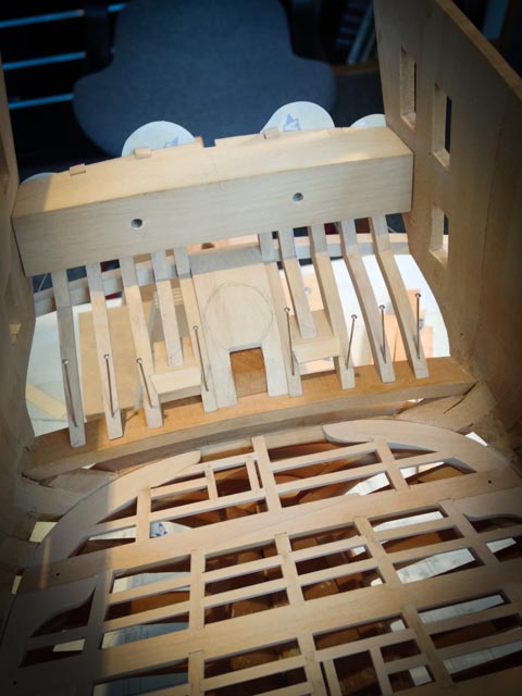
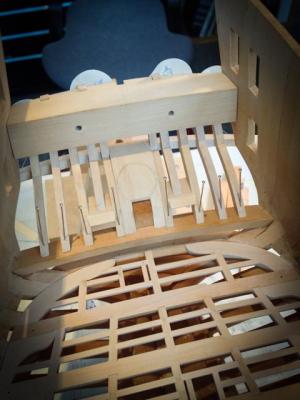
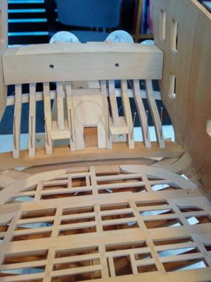
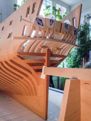
Hi everyone, A little more progress. I used the jig to shape the quarterdeck transom, by gluing sandpaper on the upper surface of the jig to fair the transom to it. I also fitted three clamps to hold the transom in place while I marked the dovetails with the vertical counter timbers. The first photo shows the transom before dovetailing, set forward from the aft face of the counter timbers so the frames for the lights can fit flush between the vertical timbers. The original Bellona model shows this offset between counter timber and transom, and it took me sometime to figure out; perhaps I'll do a drawing later to show this. The second photo shows the counter timbers dovetailed into the quarterdeck transom. I only have to make the upper counter moulding, fair the faces of the counter timbers, and it is time to glue up! That will be another month at my current rate.... Mark

-
ROYAL CAROLINE 1749 by Doris - 1:40 - CARD
SJSoane replied to DORIS's topic in - Build logs for subjects built 1501 - 1750
Hi Doris, Your model is gorgeous. I just noticed the smoke discoloration at the top of the stove chimney. Very nice touch! Mark- 883 replies
-
- 3
-
-
- royal caroline
- ship of the line
- (and 1 more)
-
Beautiful work, Michael, as usual. And every step makes it look even better! Mark
-
Hi everyone, Quick update. I roughed in the helm port, which will be refined in size once I have a rudder to check against it. Getting this port shaped meant I could finally fit the center counter timber, which mortised into it. I don't know if this is the right joint here, but it made sense when I looked at it all. All pieces are now shaped and fitted. Time to cut the dovetails at the tops of the counter timbers, and fit the quarterdeck transom.... Mark

-
Thank you Adam, Sailor and Doris, for your kind comments. This really does turn out to be the most challenging part of the build so far, keeping track of so many parts all having to align to different angles and curves in three dimensions. I thought I had a good ability to visualize in 3 dimensions and to understand 2 dimensional drawings that represent 3 dimensions; but this stern goes entirely beyond my skill to visualize it. I had to start building to understand the interrelationship of the parts in 3 dimensions. All part of the fun! And Doris, I appreciate your comment about wooden frame. Your build in card continues to amaze me; I am sure you have the more difficult material to work in, and you do it so exceptionally well. Best wishes, Mark
-
Thank you, Grant, Gary, druxey and Ben. It feels like a team effort, with all of the help everyone has given on this. Ben, you can count on help with your Pegasus! Mark
-
Michael, it is a joy to see your craftsmanship. When I read your weather updates, I know what is coming our way down south... Mark
-
Very nice, Remco, a level of detail not seen before. You will need to have a book of photos beside your ship when it is done, to show off all of the details... Mark
- 1,215 replies
-
- 2
-
-
- sloop
- kingfisher
- (and 1 more)
-
Gary, Beautiful, as always. I noticed the tubes between the pump cisterns. I hadn't seen that before. Very nice! I still don't know where my helm port transom is going. I'll keep looking at yours very carefully as a source of inspiration. Best wishes, Mark
-
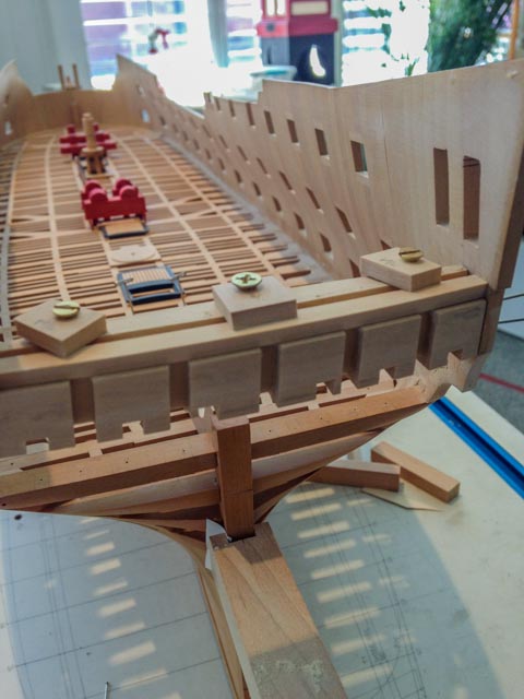
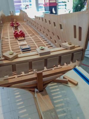
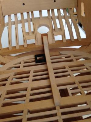
Hi everyone, A quick update on the Bellona's stern. I don't get much time in the shop these days, so it is going very slowly. Fitting the counter timbers is trickier than I ever would have imagined. The counters round back and up, and the vertical timbers taper to point some distance above the hull. But not all taper. The ones on either side of the stern post are vertical; and the ones on the outboard side of the gunports are vertical alongside the gunport and then crank to align with the taper of the others above the gunport. I have shown these cranked timbers in the first photo. Everything is loosely fitted right now, and not yet sanded to final fairing. I haven't yet figured out the rudder port shape, so it is just a slab sitting in the place where chocks will have to go, with a penciled in shape of the port. I may build the rudder next to see what the shape of the port will be. It is pretty thin construction here. I can see why a broadside raking the stern would devastate the decks. Good thing I am not in a hurry, and don't have any raking broadsides coming my way yet... Mark

-
It is always a pleasure to see your work under construction.... Mark
-
ROYAL CAROLINE 1749 by Doris - 1:40 - CARD
SJSoane replied to DORIS's topic in - Build logs for subjects built 1501 - 1750
Doris, Stunning work. I would never believe this is possible if I did not see it on your build log. Mark- 883 replies
-
- 1
-
-
- royal caroline
- ship of the line
- (and 1 more)
-
Beautfiul work, Ed, and always a pleasure to see the photos of your building techniques. Mark
-
Hey Gary, I think I see the solution to my problem in your model. The helm port transom when it is cast down has also moved forward. That means I can align with the stern post at its lower level, and still have it sit down on the vertical timbers if it moves back a bit on the sides. I'll try to do a drawing later.... Mark
-
I was thinking about a nice Georgian style table and chairs for my Bellona's captain's cabin. Perhaps I can hire you to give me miniature furniture making lessons. Just about beyond comprehension what you can do, Remco. Well done. Best wishes, Mark
- 1,215 replies
-
- 2
-
-
- sloop
- kingfisher
- (and 1 more)
-
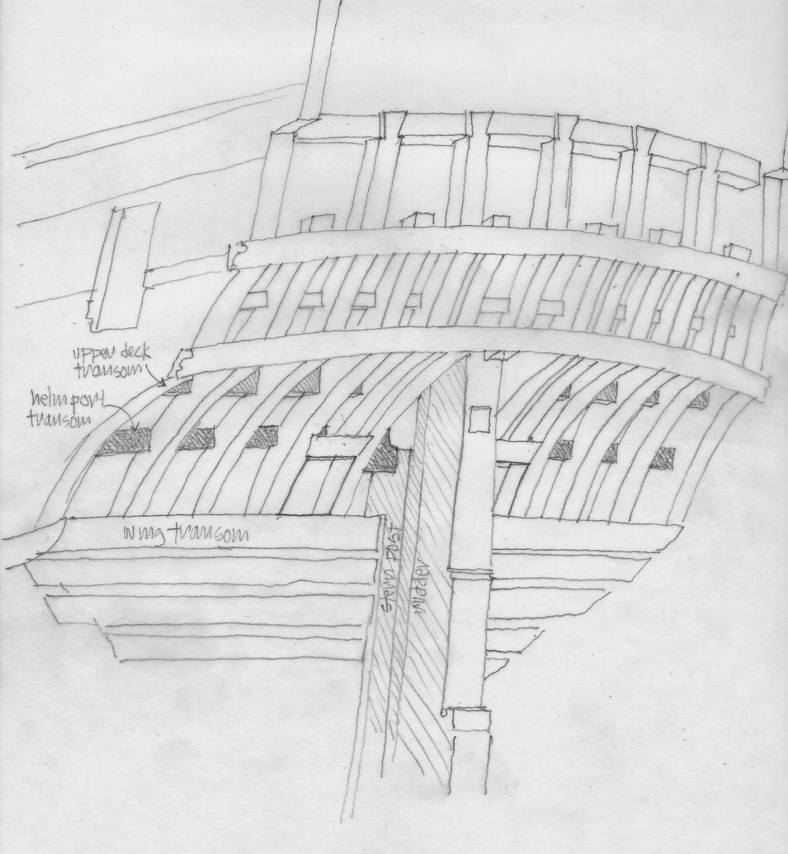
Hi everyone, It is getting more interesting. I have attached a drawing based on the NMM photo of the 1760 Bellona model, highlighting where the transoms appear to be. It looks to me like the one I have labeled helm port transom does sit down on the vertical counter timbers, and then drops down to the side of the stern post. So it definitely is not on top of the post, or there would be no room for the tiller. But Gary is right that it is not aligned with the aft side of the stern post as I had originally drawn it. It appears to line up a little abaft of the rabbet in the stern post, which, if it is 10-12 inches thick, would put it right in the middle of the stern post. It either has a bridle joint, or the two halves tenon into the side of the post. Also note that the heads of the gun ports are a little lower than the helm port transom. More difficult is that when I draw the helm port in this new more forward location on the stern post, the two sides are now too high to sit on the vertical counter timbers. I have got to keep playing with this in section, before everything lines up to look like the photo of the original model... Best wishes, Mar

-
Hi Gary, You are right; when I look at the Bellona photo again, the aft face of the helm port transom is forward of the aft face of the stern post. But the aft face seems to intersect at a line just about the same as the rabbet in the stern post, and that would have the transom hitting the center of stern post which could provide a bridle joint between the two. I am having trouble getting the helm port transom beyond the canted center part to intersect the lower counter timbers in this new position, and I will send a drawing later to show this. But for now, do you have the specifications of the vertical counter timbers, in particular the fore and aft width where they sit on the wing transom, and at the lower counter knuckle? I may be working with the wrong dimensions, which would cause my transom in the new correct position not to intersect the vertical timbers. The dimensions I got from Steel don't seem to make things line up. Mark
-
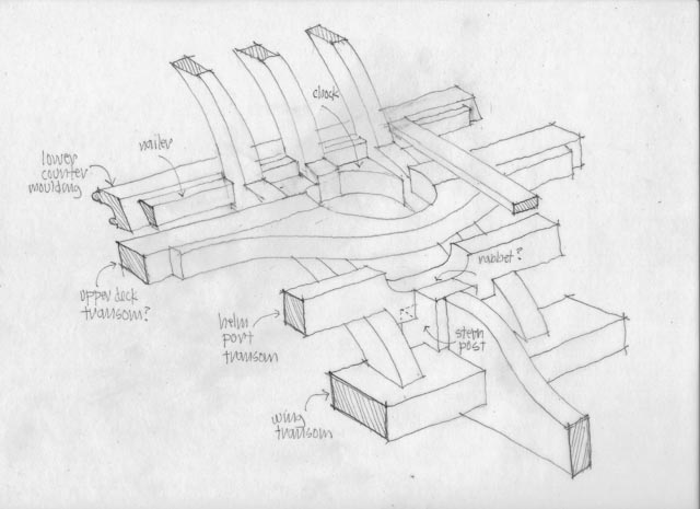
Hi everyone, Thanks, druxey, Gary and Ed. It is so helpful to have your expertise and critical eye looking at these reconstructions. This website supports the most remarkable community of learners. This shared detective work is almost as fun as the actual construction... So, here is the latest reconstruction in light of recent insights from all of you. The biggest change is information that there was likely no rabbet into a transom for the upper deck planking. To give the planking some landing, I have shown a "nailer" fayed to the fore side of the lower counter moulding. Some of the planks are going to run right into the fore side of the vertical timbers and vanish down to no thickness at the sternmost end, but it is what it is. I have also shown chocks like the ones Ed shows in his book, because the lower counter planking will need something to land on at the edge of the rudder port. There may be chocks further down, but I can't visualize that yet. And I am showing a rabbet where the helm port transom intersects with the top of the stern post. I don't know how I am going to cut that rabbet in the post at this point, but we'll see. Gary, do you think this is the way they likely intersected? Thanks again for your outstanding help. Best wishes, Mark

-
HI Gary, Thanks, this is very helpful. I have sent you a PM with some additional information that show some of the unexpected complexities I am trying to resolve with this drawing. Maybe we can review the contract information with the info I have sent you. Best wishes, Mark
-
Thank you, druxey, that makes sense to label the last beam aft the transom. In my photos of the Bellona stern, the next one forward avoiding the rudder head clearly sits down on the counter timbers and is cut with an exposed rectangular end, so I'll go with the curved beam fayed onto the fore face. The more I play detective on these complex constructions, the more impressed I am with the shipwright's art 250 years ago. But this drawing does look eerily like a space ship out of star wars.... Thanks again for your erudite help and good eye for detail. Mark
-
New Video on Basic Soldering for Scale Models
SJSoane replied to P_Budzik's topic in Metal Work, Soldering and Metal Fittings
Thank you, very nice and informative. -
Table Saw Blades and other bits and pieces
SJSoane replied to mtaylor's topic in Modeling tools and Workshop Equipment
What a good idea. I probably could have retired years ago if I had not spent every spare penny on tools...