


schooner
-
Posts
723 -
Joined
-
Last visited
Content Type
Profiles
Forums
Gallery
Events
Posts posted by schooner
-
-
Laying out the gun ports
I’ve been spending a LOT of time measuring, marking, comparing, erasing, remeasuring, etc, etc, etc as I’ve tried to figure out where the gun ports are supposed to go. It’s no surprise to anyone on this site that one of the great things about working with wood is that there are few unrecoverable errors but getting the gun ports wrong on a model of this size might be one of them so that is why I have been doing all the ruminating.
In the process of figuring out where the gun ports go I also dry-fitted the PE transom and figured out I would need to raise the after part of the bulwarks a little so I added a 1/8” strip and then sanded it down to match the sheer of the quarterdeck. Later on I’ll probably have to take off most of what remains.

The instruction call for laying out the gun ports using the station lines and the waterline. I did a little of the former and ignored the latter. I finally figured out that the key reference for the gun ports is the height/location of the gun deck at each port location. If the port is too high or too low it would be a real mess trying to fix it so the cannons will protrude properly.
Since all the station lines are probably a little off because of the difficulty bringing a line from the keel to the bulwarks I decided to just pick an amidship station line and then mark the fore and aft lines for each gun port from it, that way only the error of one station line is included rather than the compound errors of using all the lines. The only exception was for the forward most port on each side - the plan's side view can't account for the curve of the bow so I measured their location from the stem using the overhead plan.
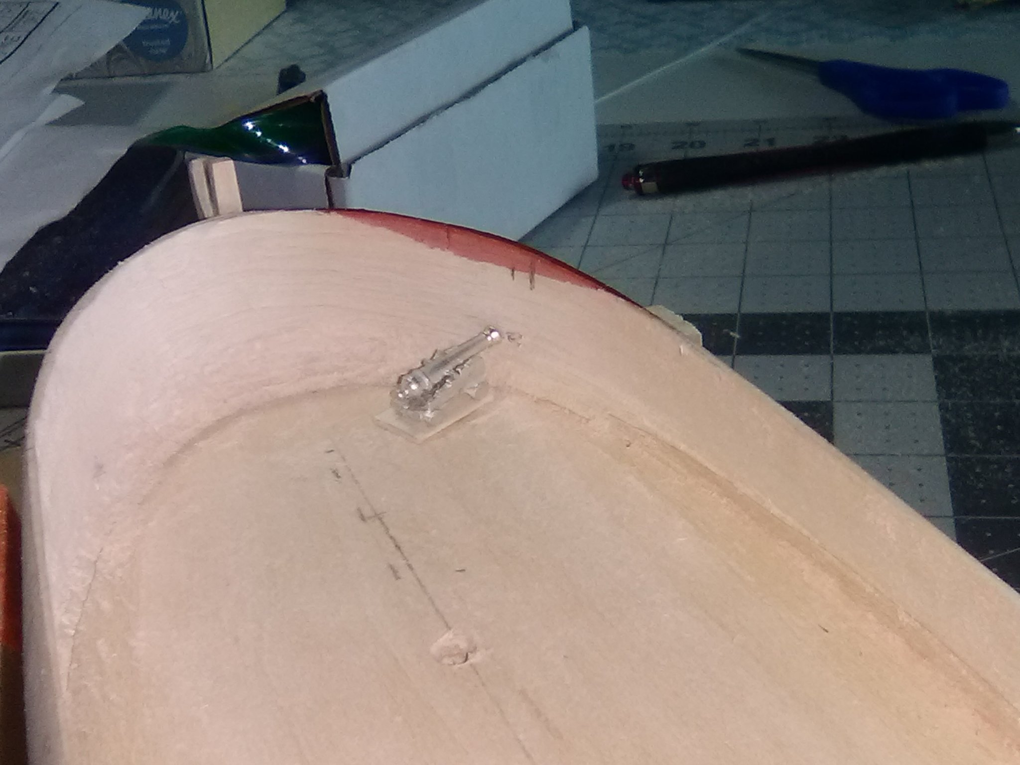
To lay out the upper and lower limits for each port I used a trick from the instructions;
- I put together the carriage and barrel for one of the cannons, glued it to a small piece of the decking that will cover the gun deck and then pushed the barrel up against the inside of the bulwark at the port’s approximate location (note for anyone building this kit - the instruction book and parts list both refer to 1/16" scribed decking, my kit has 1/32", which is fine with me since it will be easier to work with.)
- I made a pencil mark and then transferred that mark to the exterior of the bulwark and drilled a small hole.
- If the hole matched the interior pencil mark I knew I had the line for the vertical centerline of the port, if not a made a correction and drilled another hole until I got it right. Then all I had to do was measure from the port’s center mark up and down to get the port’s vertical dimensions marked.

Once everything was marked and checked against the plans again I was ready to start cutting them out (or to put it more accurately drill and file them out). It is a little slow going, I can only do one port in a sitting or I’ll get careless. 3 down, 17 to go.
-
-
-
-
I'm working on a 1775 vessel that was built too early to be coppered. All the models I've seen of ship's of that period show a white coating below the waterline which I assume is some sort of white lead to combat worms and other destructive organisms.
My question is: In order to accurately represent that underwater coating should I assume it was put on so thick that individual planks were not really visible and therefore I should use filler on my completed planking in that area so that I will have a smooth finish. Most builds I've seen seem to have smooth, off-white underwater hulls but usually the photos are not close-up enough to tell about the plank seams.
Any feedback would be appreciated.
-
-
-
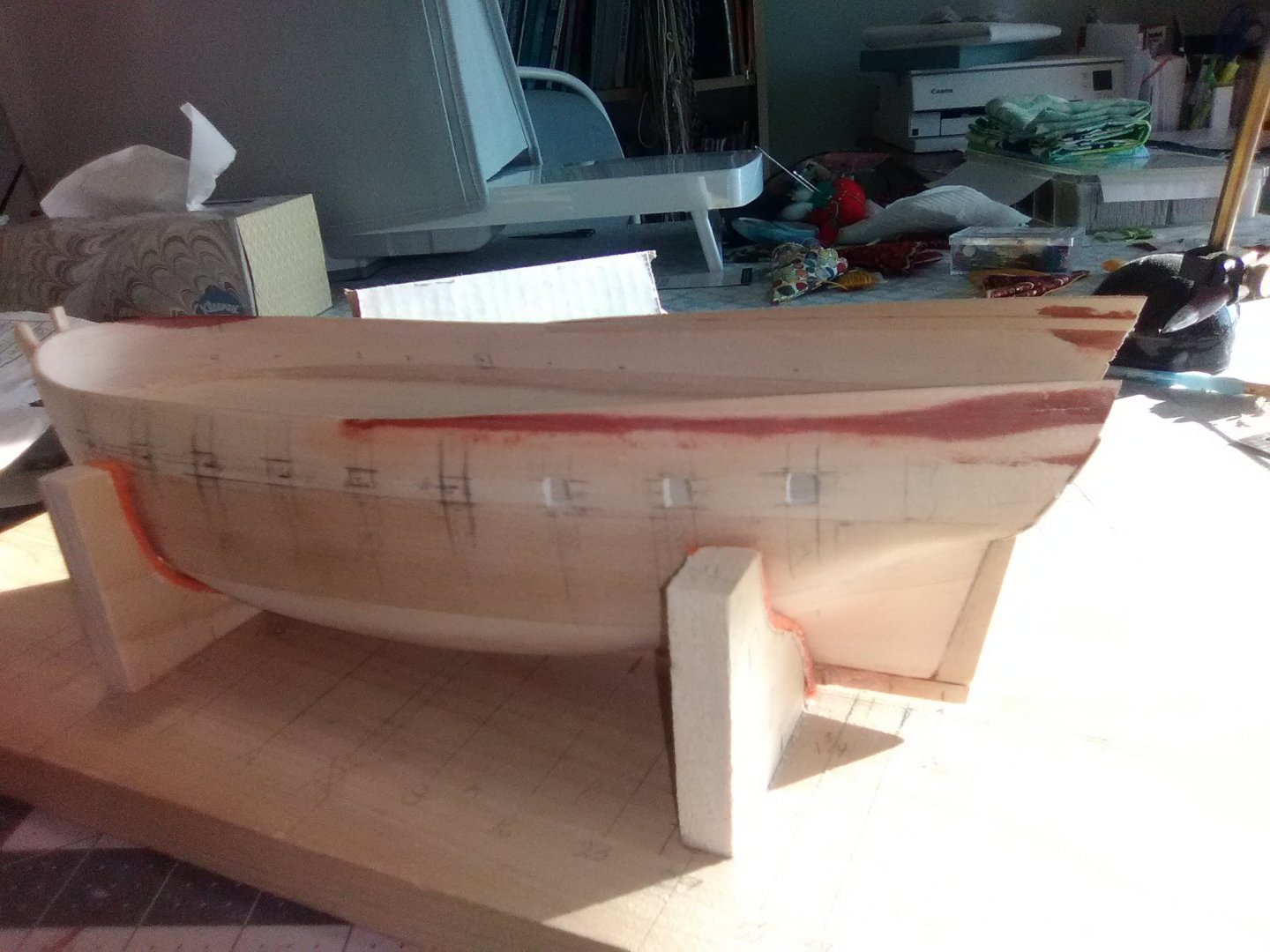
Thinning the bulwarks
This is the step that I have been dreading, I’ve never had to do it before on any of my builds and I’m not very good with chisels so the thought of having to reduce the bulwarks by about 80% to only 3/32” thickness almost kept me from buying this kit.
The instructions go thru the same process for thinning that I have seen on build logs using a hobby knife, small saw, chisels, files and sanding blocks but it also mentions that a rotary tool can be used so that was they way I decided to go and it turned out to be much easier and less time consuming than I could have hoped for.
The bulwarks start out at about 3/8” thick. They need to come down to 3/32”, at least at the top, and the bottoms can be 5/32 but 3/32 is more accurate. They also have to slope inboard as they go up (tumblehome) but since the ALFRED started out as a merchant ship the instructions said she would not have had as much tumblehome as a purpose built warship.
I figured out that the best way to handle the tumblehome was to sand the curve shape into the outboard side of the bulwarks, then as long as I maintained the same thickness from top to bottom the inside of the bulwarks would have the same inward slant or curve.
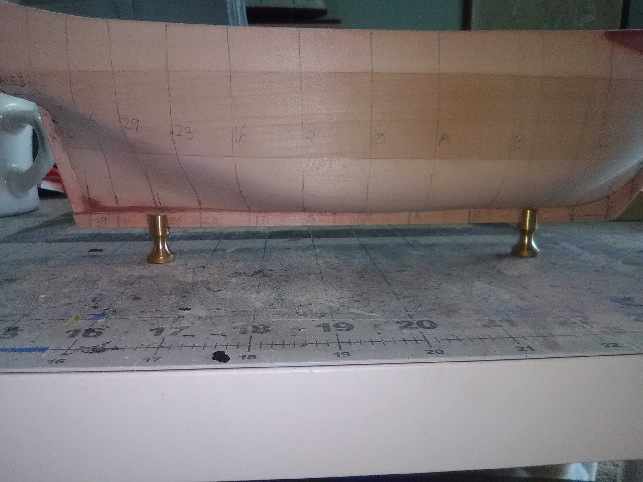
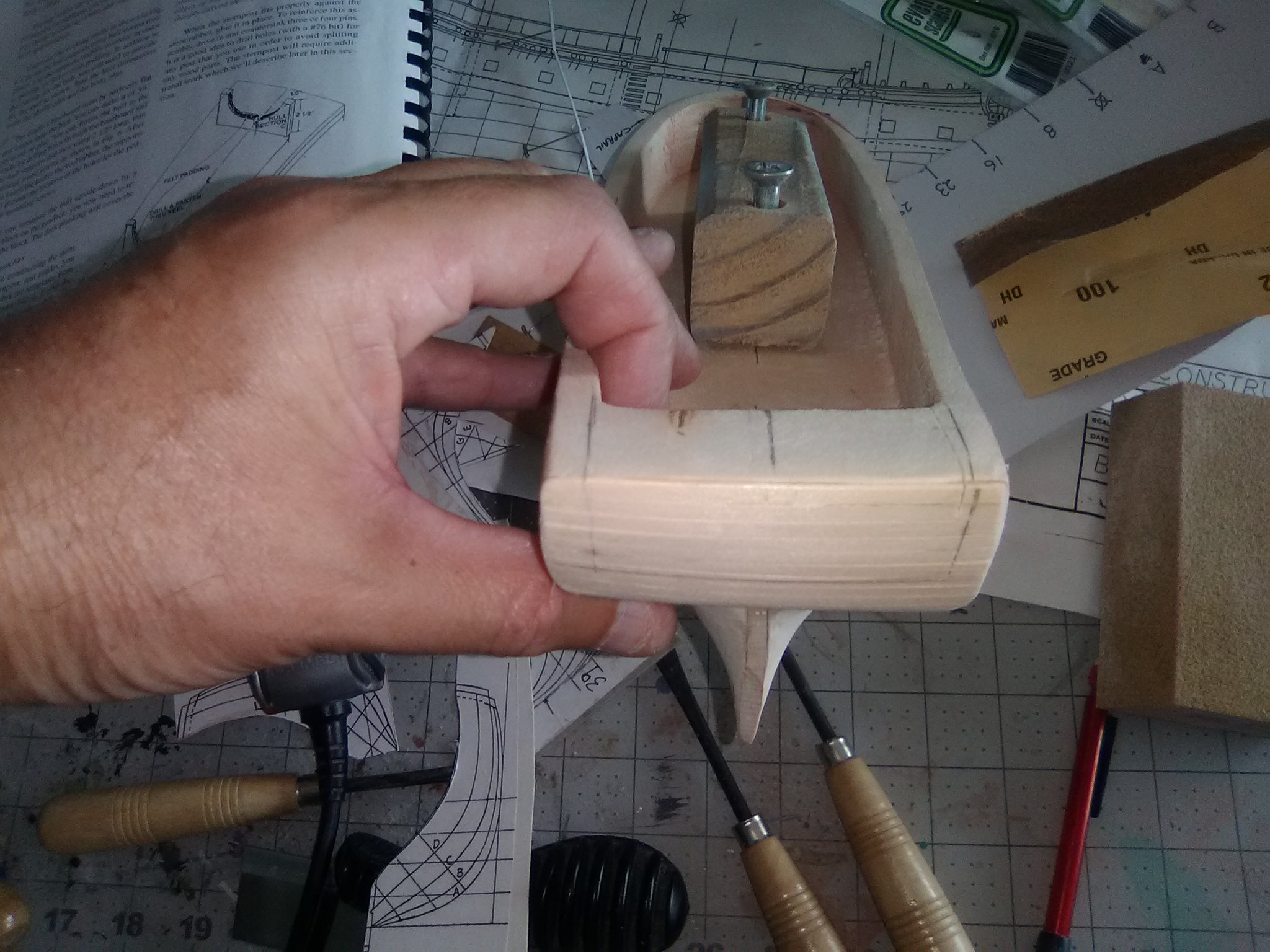
I marked the transition point where the bulwarks go from slanting to vertical where the curve of the bow begins - that would be the forward limit for shaping the outside of the bulwarks. I also marked the location the wales - that would be the lower limit. Using a hand held vibrating sander it was quick and easy to bring the thickness down to the outboard line on the top of the bulwarks (see the last photo of the previous post) then to impart a curve from the top to the lower limit line. By looking at the hull frequently I was able to remove any flat spots and keep everything fair. This is how things looked after the outside was done; (not sure why the sternpost looks crooked in the following photos - when I saw them I thought "Oh no, how could I have missed THAT!!!) but when I checked the model the sternpost is straight and plumb. Guess my photo skills are worse than I thought)

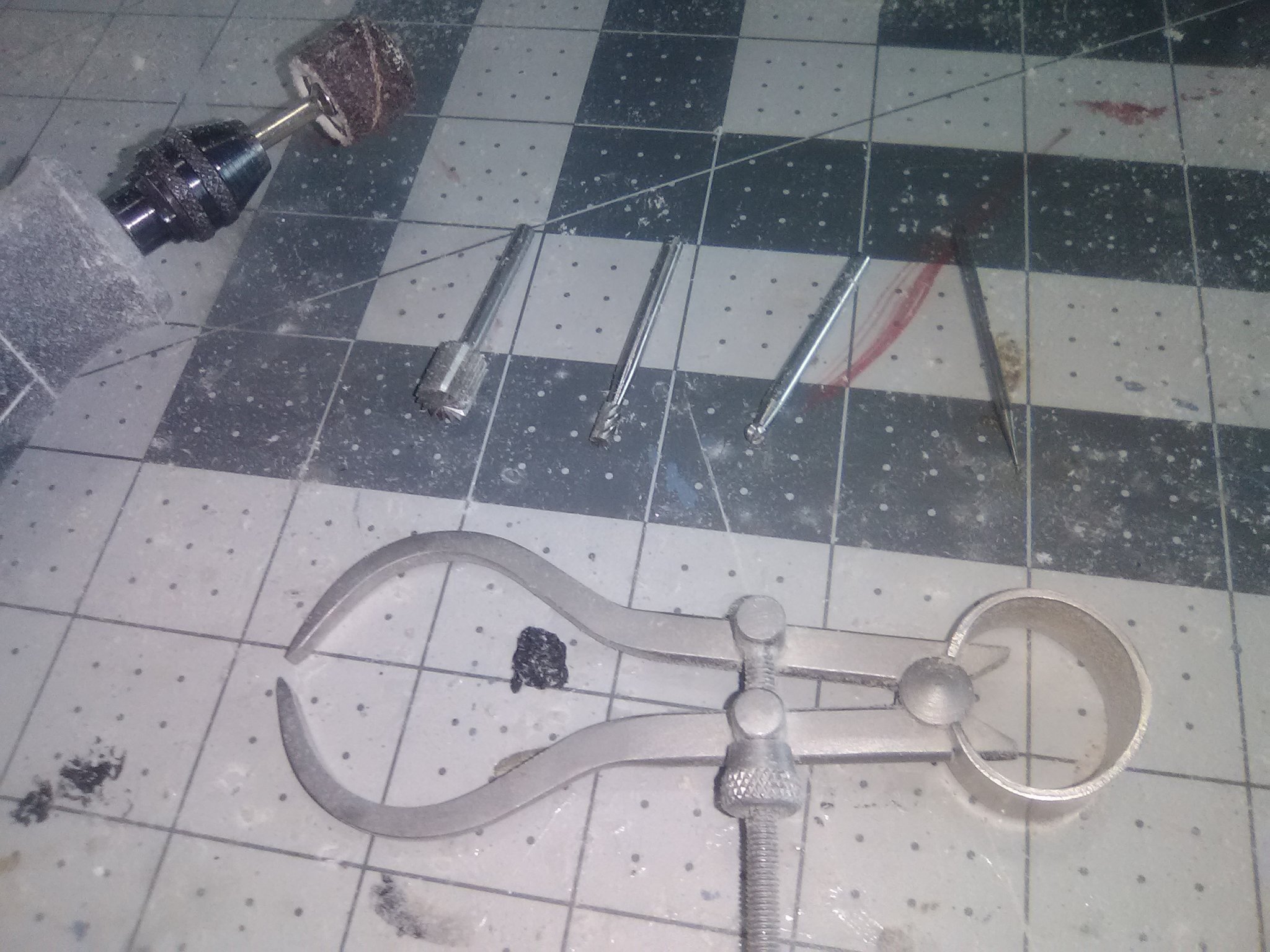
This is what I used to handle the inside of the bulwarks:

The rotary sanding drum took care of most of the work. The calipers are essential for this job. I started out to bring the bulwarks down to 6/32 along their entire length, checking frequently with the calipers. After that is was just a matter of setting the calipers at 5/32, and repeating each 1/32 until everything was 3/32 thick. Its important go sloooow and use a light touch keeping an eye on the orientation of the sanding drum to the wood. Be ready to deal with a LOT of sawdust. When finished it's surprising how thin 3/32 is, so thin that they are translucent when held up to light!

The only remaining job, and one that took about as long as everything else combined was the rotary drum left a “shelf” along the deck about 1-2mm high were the bulwark has been removed. The cutters shown above were used along with sanding sticks and a sanding block, and even a curved chisel to make the corner between the bulwarks and deck sharper. I may have to do a little more in that area when it comes time to fit the scribed decking.
I plan to plank the inside of the bulwarks (ceiling) and the outside wiich will bring their thickness up to 4/32, thin enough that the cannon barrels should extend far enough out of the gun ports to look realistic.
Next step will be making the location of the gun ports and cutting them out.
-
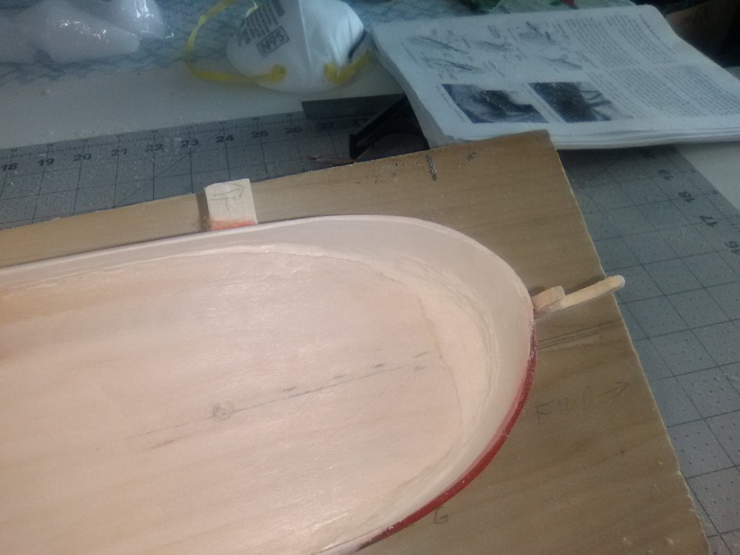
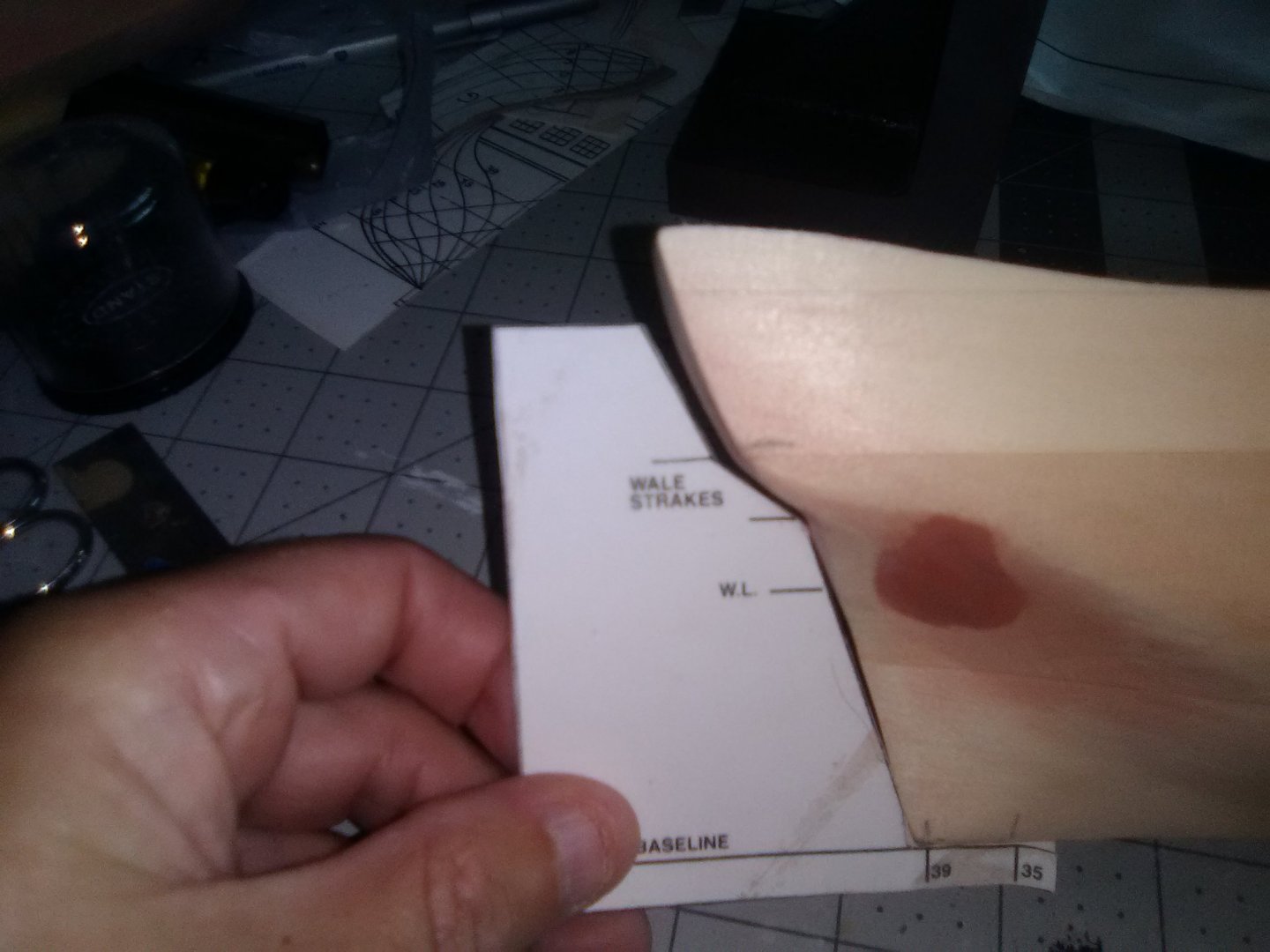
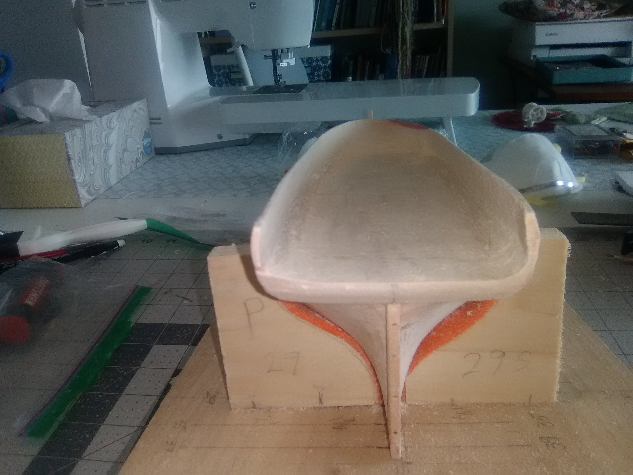
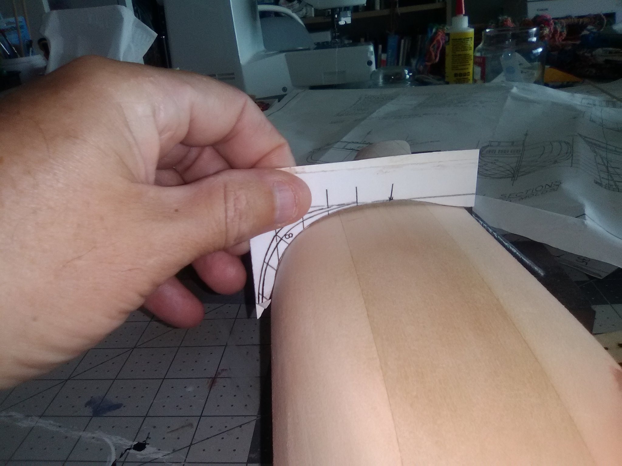
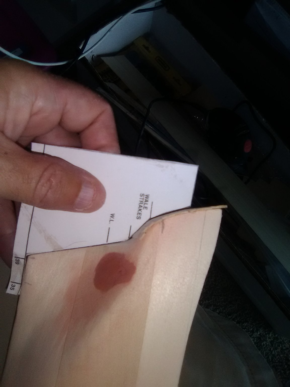
Hi CT, nice to know someone is looking at my old build log!
I think you are in good shape as regards to the bow template vs your hull. The template assumes the keel is not in place so the photo you have showing the red circle looks pretty good to my eye. As you sand off that plug on the bow things should start to look even better.
Tim
-
Hi Bruce,
Sorry for the delay in getting back to you but I did not receive a notification of your posting. I'm happy to help with questions but it would be best to contact me via message. All you have to is go to my last posting in this log, click on "schooner" at the top of the box and select "message" and I will see it on my phone right away.
That said, it has been about 8 months since I completed the kit and I don't have the direction book anymore (I should have kept it) so I can't work from part #'s but I remember the piece you are talking about. Yes, that piece may well be taller than needed which is good since it allows you to sand the top to get a snug fit with the roof piece. bear in mind that this piece has a definite slope when installed so you need to sand the bottom edge so that when it is laying against the side pieces the bottom fits the deck with no gaps. I can't remember if the deck had much camber in it (the center higher than the outboard edges via a gentle curve - helps water drain off) but if it did you may have to sand a little more off of the center of the bottom than the outboard edges.
Once you have a good fit, glue it in place. Take the roof and test fit itif the C4 part is too tall start sanding the top edge, remembering that the top edge will also have a bevel in it since it is on a slant. keep sanding a little and test fitting a lot and you should get it to the point where the roof is in good contact with the cabin sides and C4. If you really screw up C4 you can tear it out and make a new one using the laser cut fret you cut it out of or using tracing paper to make a copy of the plans and then glueing it to the right thickness of wood and cutting it out (something you can do for most parts in that kit)
let me know if you have any more questions.
Tim
-
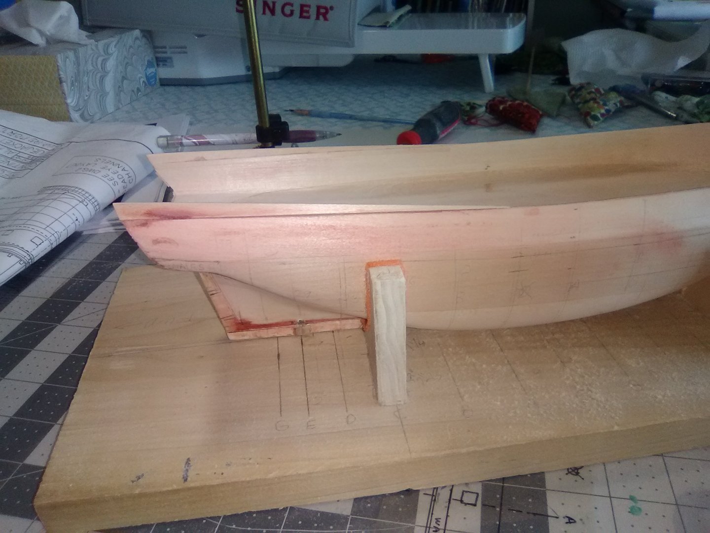
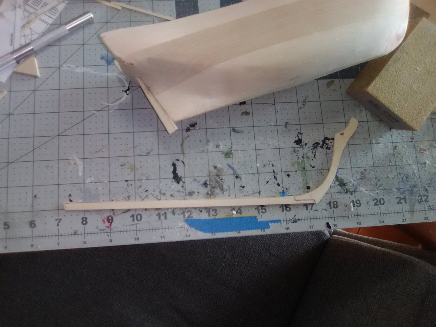
More Hull Work
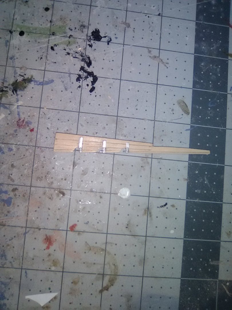
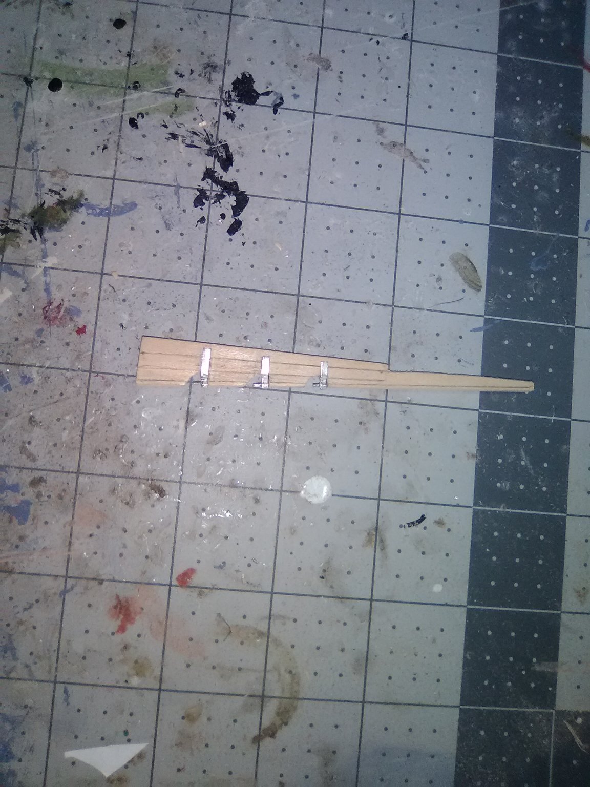
The directions call for fabricating the rudder at this point, not sure why but I did it anyway. It is just 1/8” stock cut to a trace, forward end round, aft end tapered and the “planks” imparted by running a hobby knife along the pencil lines and then doing it once more with the back side of the blade tip to leave lines that should hopefully show up after it is primed and painted. The gudgeons (or pintles, I can never keep them straight) are britannia metal.
The instructions also call for adding the stem extension, small knee and test fitting the head grating at this point. This was a real head scratcher because the directions were referring to having the grating contact parts that will not be added for a long while yet. I think it was just a case of getting carried away with the copy and paste function while assembling the instruction book.
Note from later in the build: DO NOT fit the head grating yet - its' aft edge has to fit the PLANKED hull right at the level of the main deck (which you can't tell where that will be at this point) so wait until it is time to build the ship's head (much later than now).

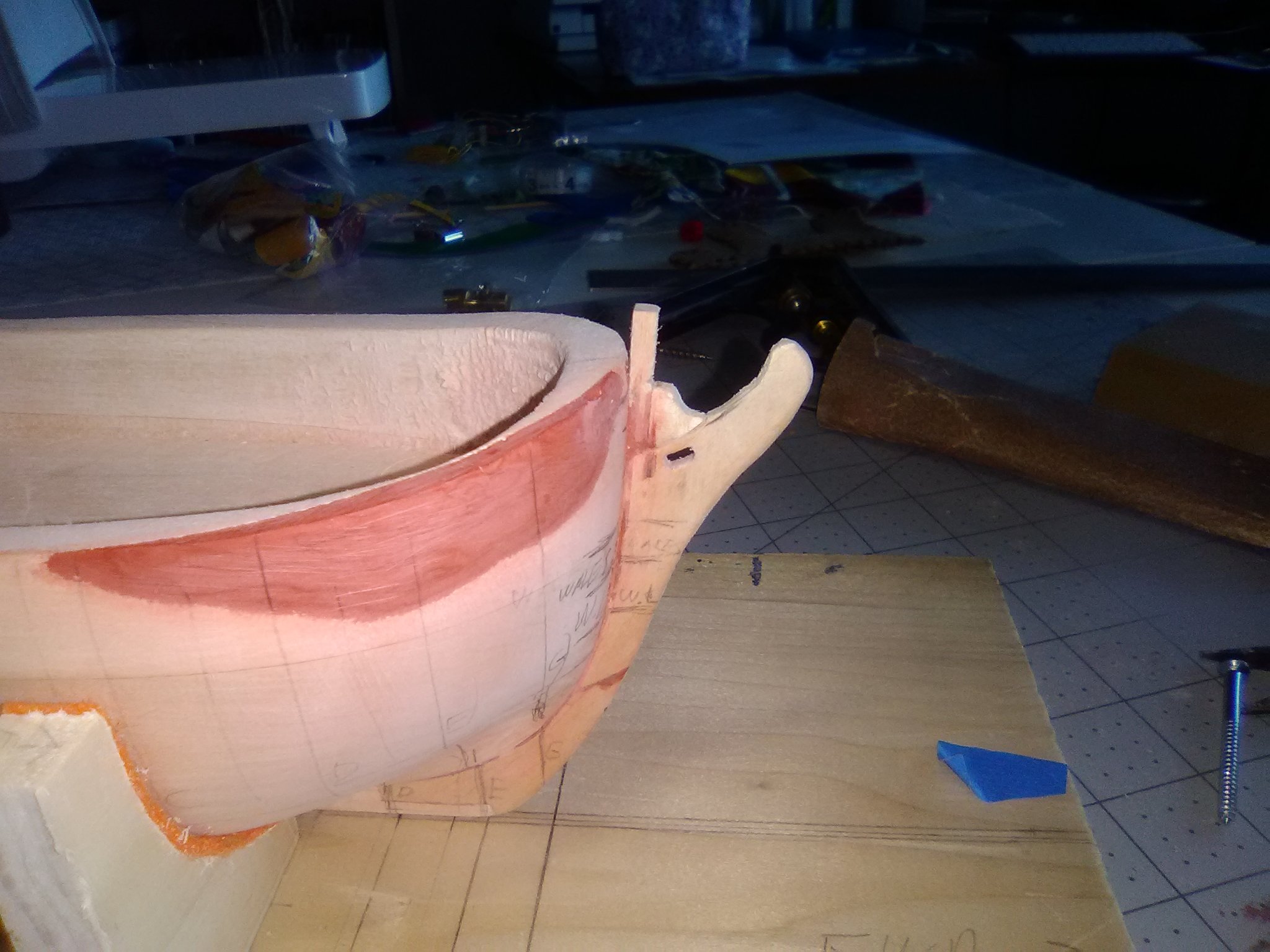
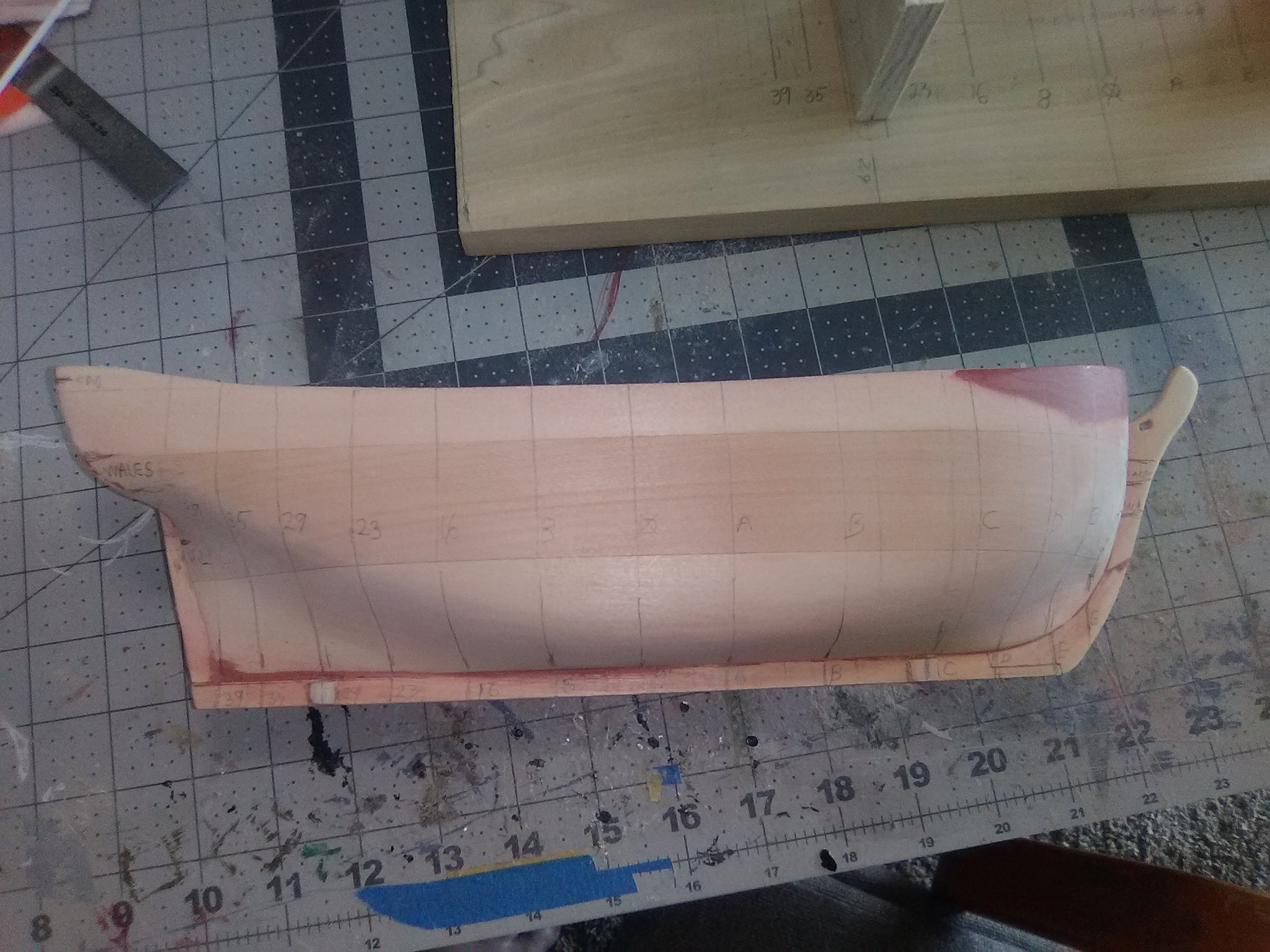
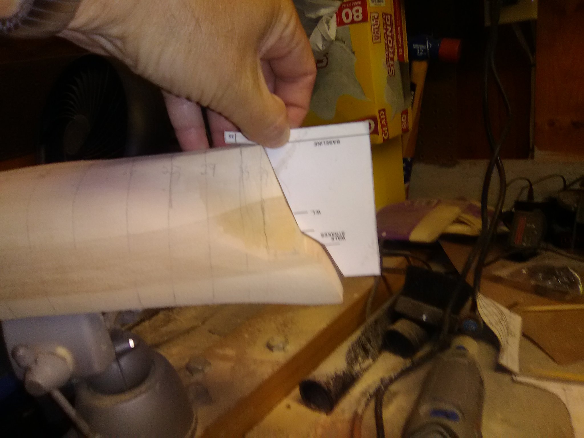
Before I could mark out the bulwarks for thinning I had to remove some excess material from the aft ends so that the bulwark shear line is straight. The material to be removed is shown by the cross-hatched pencil marks.


I had to think a while about how to lay out the bulwarks for thinning. The aft 3/4 have noticeable tumble home (i.e. they curve inward) but up where the bow starts to curve they are vertical. By marking the centerline of the existing bulwarks all around the hull then laying out parallel lines on each side to show the final 3/32” width I was able to mark where the inboard and outboard lines began to curve and marked that as the end point for the tumble home. Where the outboard line touches the current outboard edge of the bulwark will be the point where the 3/32 width will be measured from the outside of the existing bulwark all the way around the bow and material in that area will only be removed from the inboard side.
- mtaylor, Duanelaker, Bill Morrison and 3 others
-
 6
6
-
Great Job! I built her a few years back - best laser cut wood I've ever seen. Love the mounting stand!
-
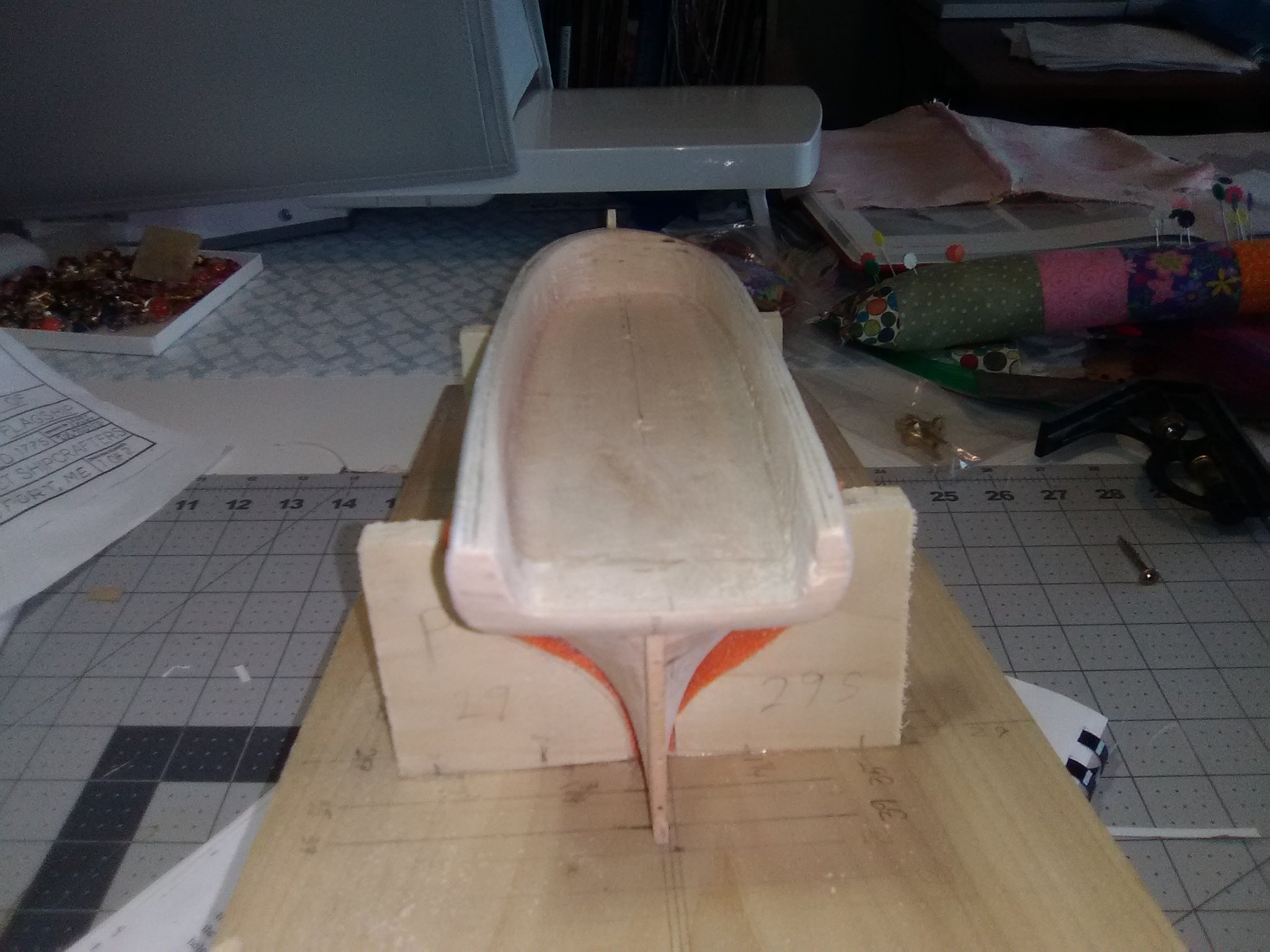
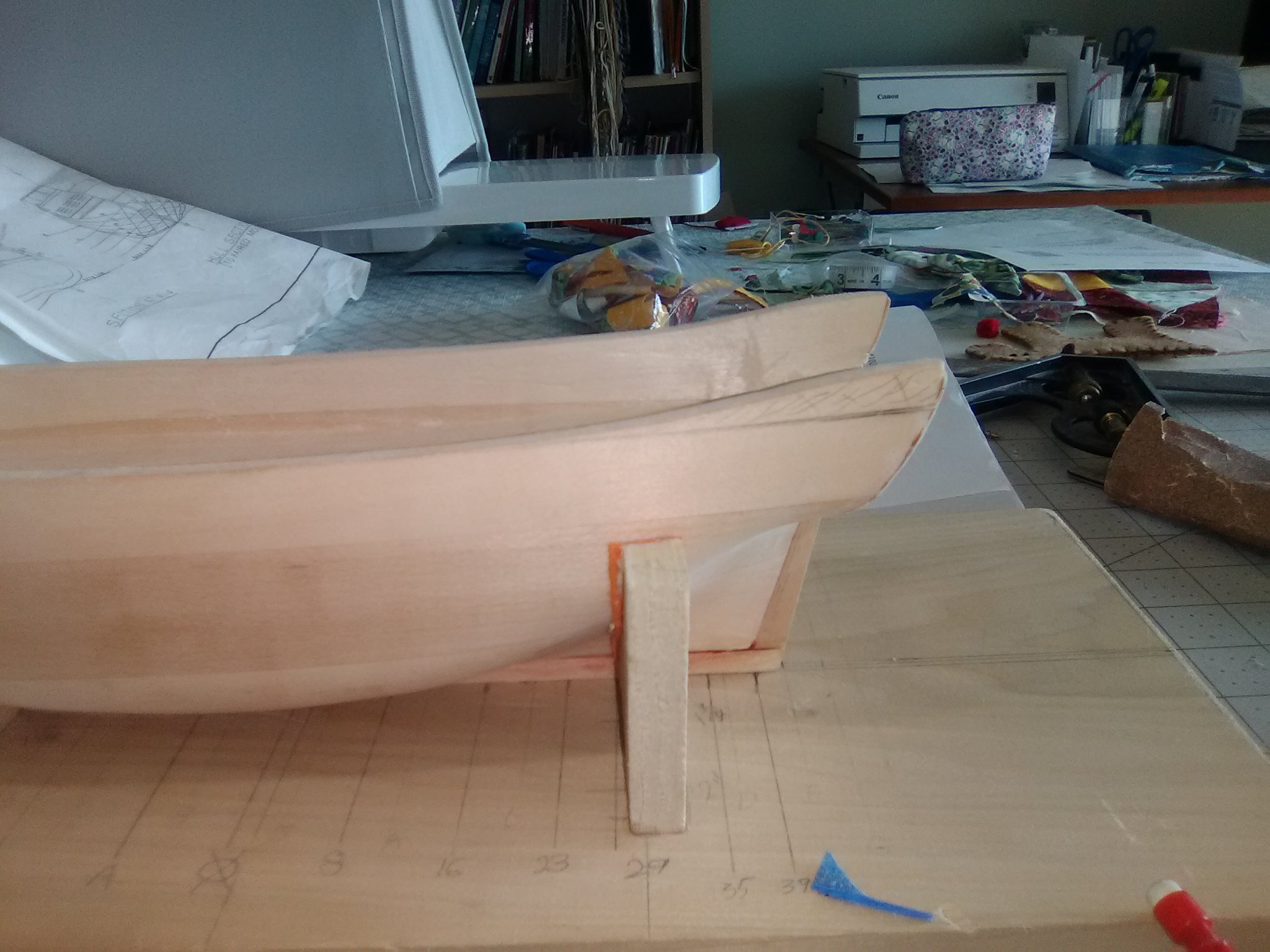
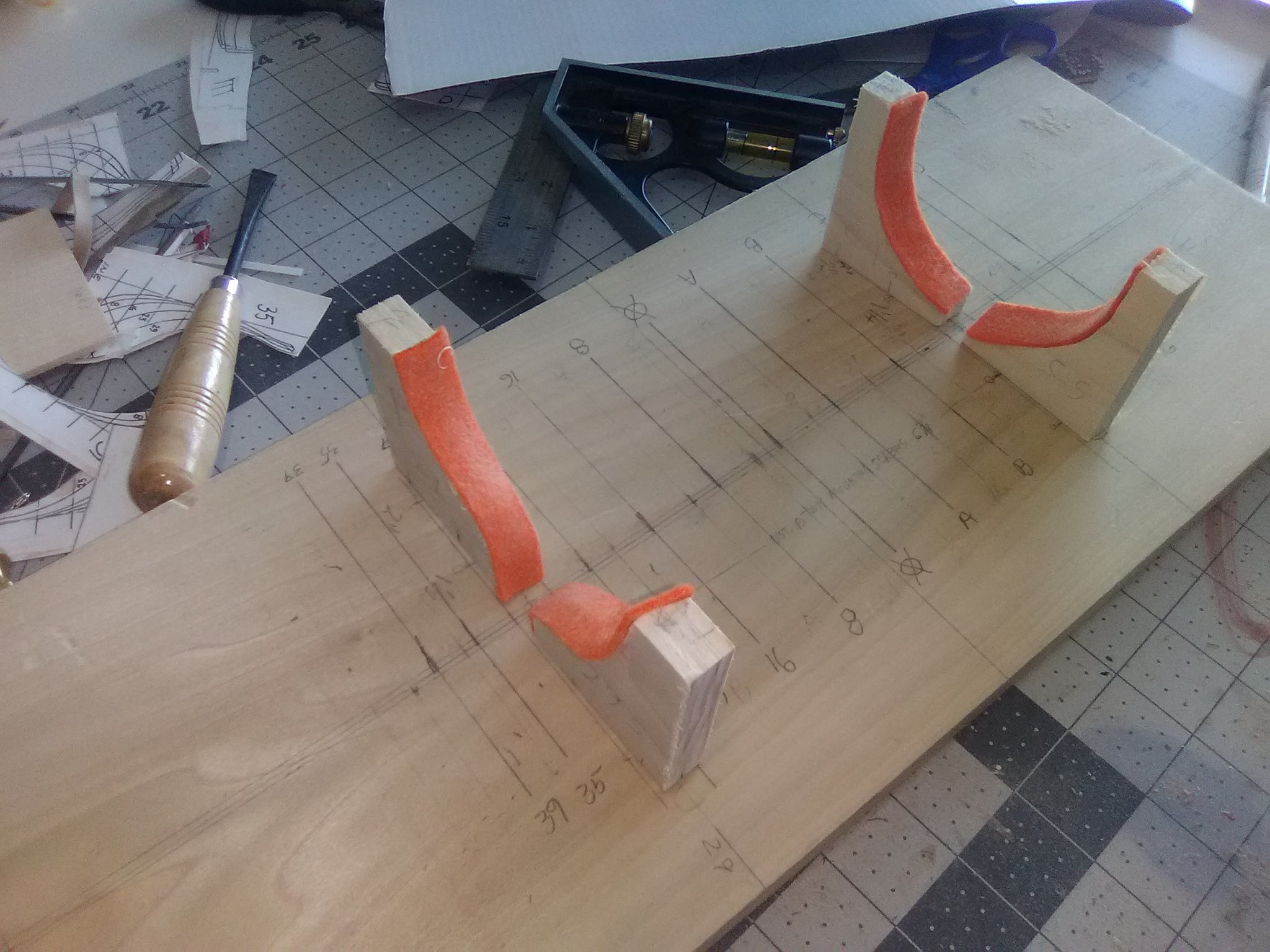
Keel Installation and Building Board
The keel, stem and sternpost are all glued and pinned in place now and the hull faired into them.

Although I have just started this build I have learned from bad experience that I need to figure out how the finished model will be mounted and take care of any drilling and blasting now rather than wait till the end and try to mess around the keel of a finished model. That said, I ordered the pedestal set for this kit from Bluejacket. The instructions caution to be careful when drilling the holes for the mounting screws into the keel because “they are almost as wide as the keel” Actually the threads on the screws are 1/8” wide, as is the keel so there is no way to screw them in without damaging the keel. Fortunately, the slots on the pedestals are 3/16” wide so I was able to glue 1/32” sheet wood on each side of the keel where the pedestals will go to provide additional thickness for drilling the screw hole - it also works out well because now the pedestal fit very snug to the keel so the model will be that much more better supported. All the station marks have been added to the hull as have the locations for the waterline and wales on the stem and sternpost.

The next step is to build the building board. The kit instructions provide all the info you need. The only modification was that I made 4 supports rather than just 2 that the instructions called for - with only a coping saw and a Dremel sander the more elaborate supports the instructions called for were just too complicated for me. The supports are not a perfect fit but with the felt liners they provide plenty of support to the hull.

I have a few small things to add to the stem area and then it will be time to trim down the bulwarks - should be a real treat.
- Bill Morrison, catopower, ccoyle and 4 others
-
7
-
Sternpost, Stem & Keel
The sternpost is pretty easy to cut out of stock using a template copied from the plans. It’s important to ensure there is a tight fit to the rabbet and then pinned after glueing for added strength.
The stem is also cut out of 1/8” sheet wood using a template. Attention needs to be paid to the direction of the grain in the wood so the piece can be as strong as possible. The scarp joint for it’s mating with the keel has been cut, as has the gammon hole. Next steps for the stem are drill out the holes fore the pins, taper it’s forward edge and then round it, glue it in place and use the holes to drill into the hull itself for the pins and then add some small stuff at the top.
Note from later in the build: Don't bother cutting out the gammon hole at this point - its' location depends on the final positioning of the bowsprit which happens much further down the road. I ended up redoing my gammon hole.
-
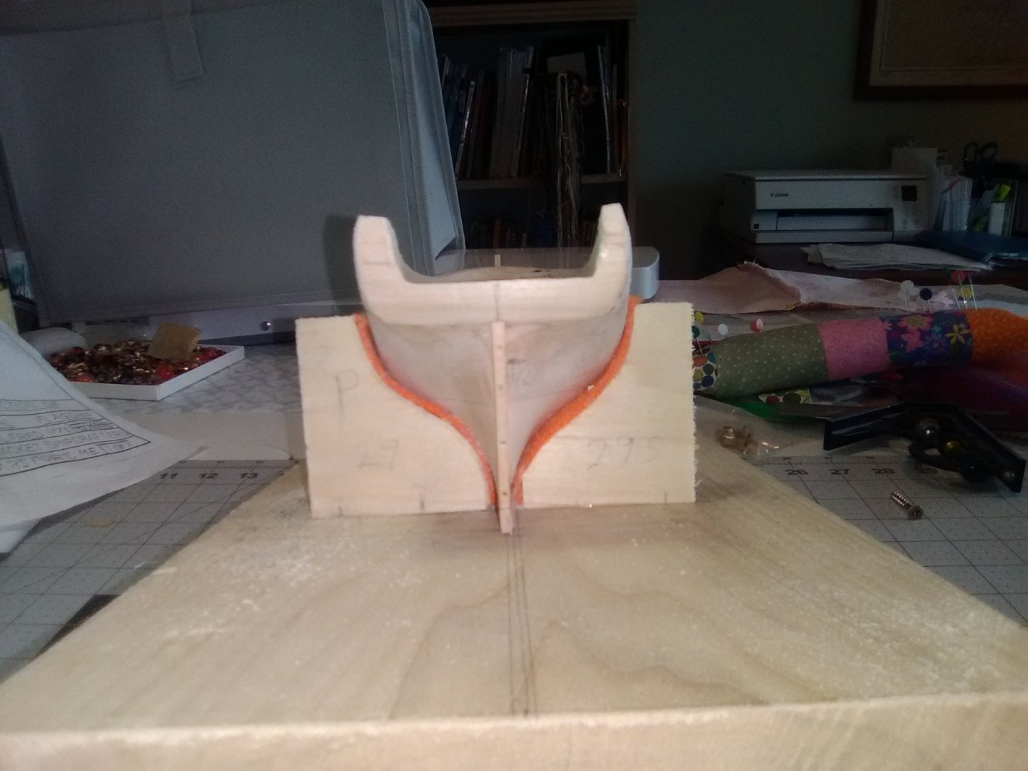
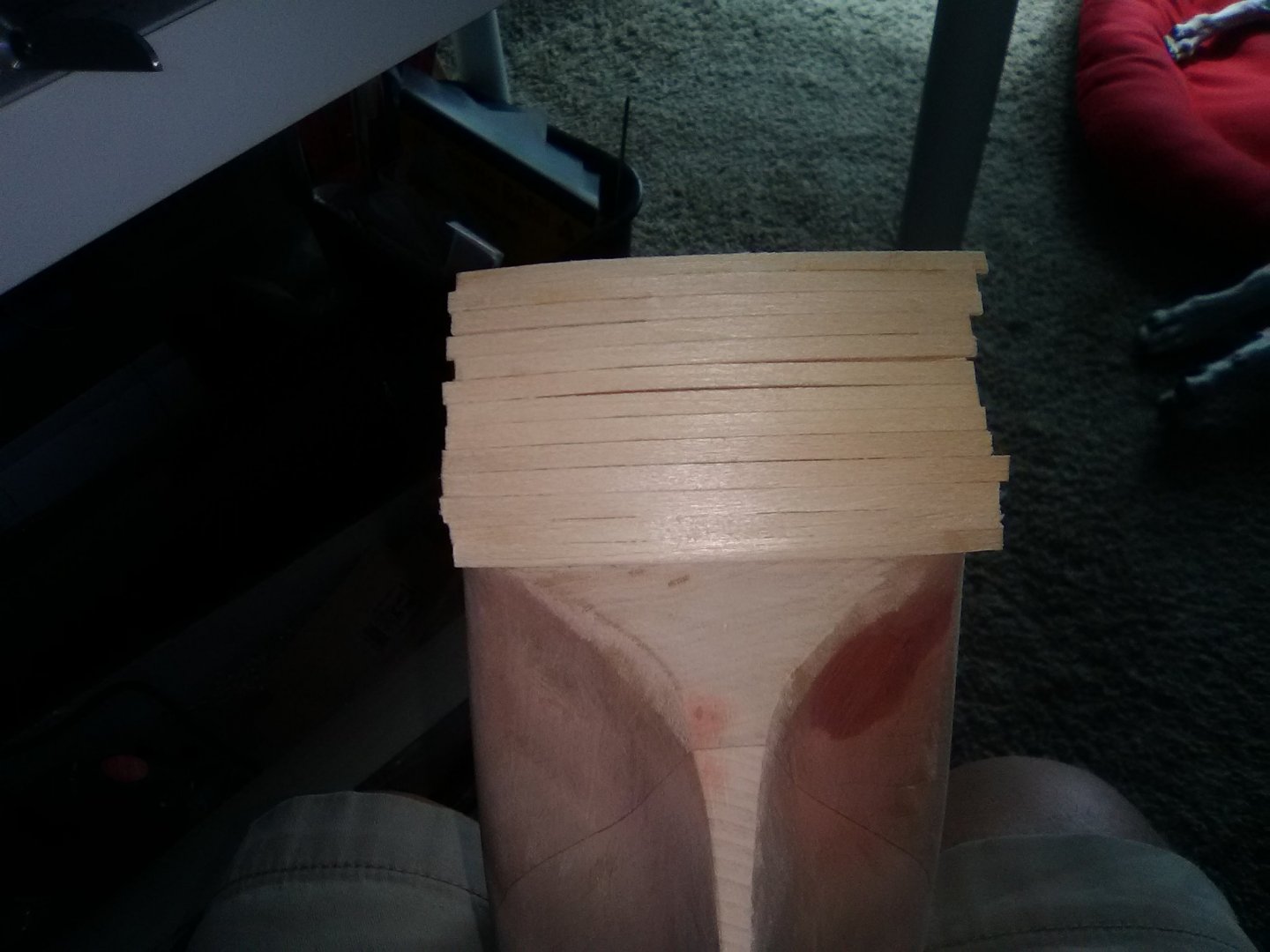
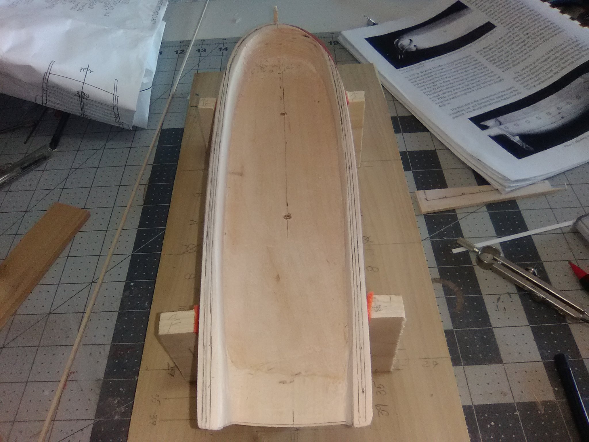
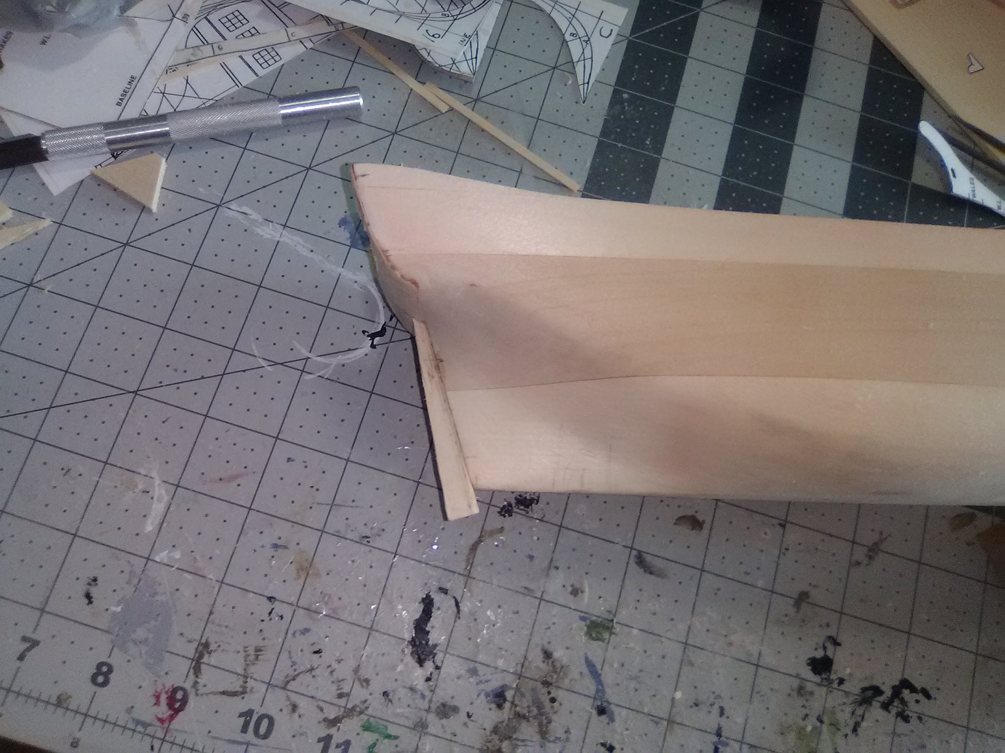
Final hull shaping
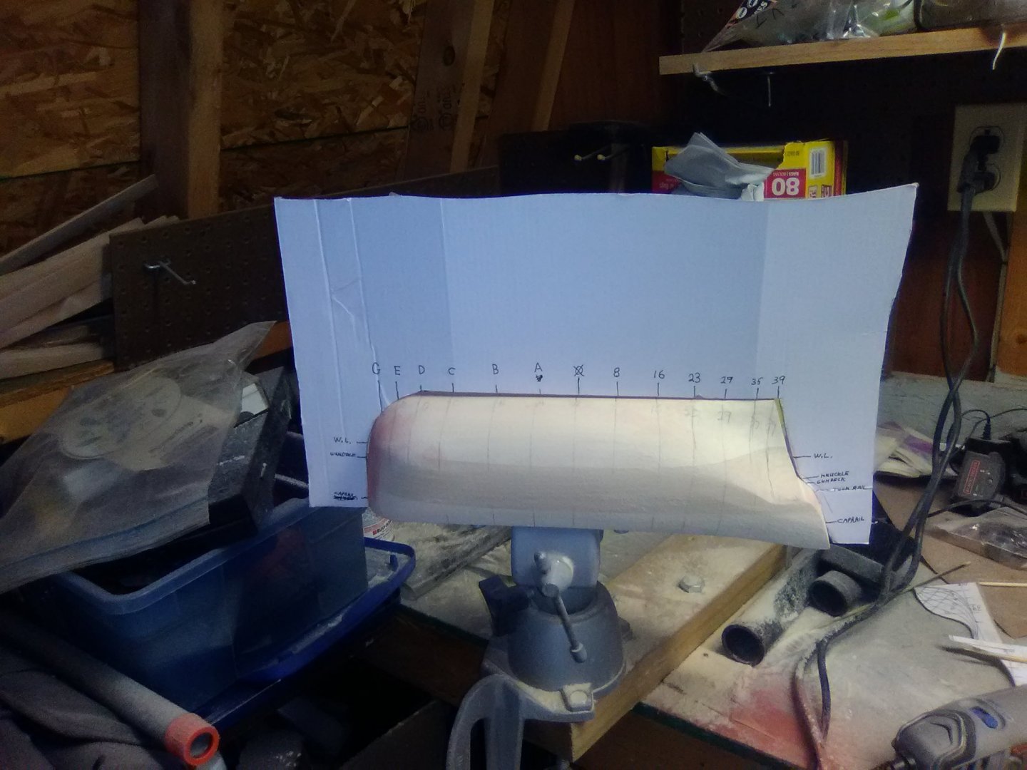
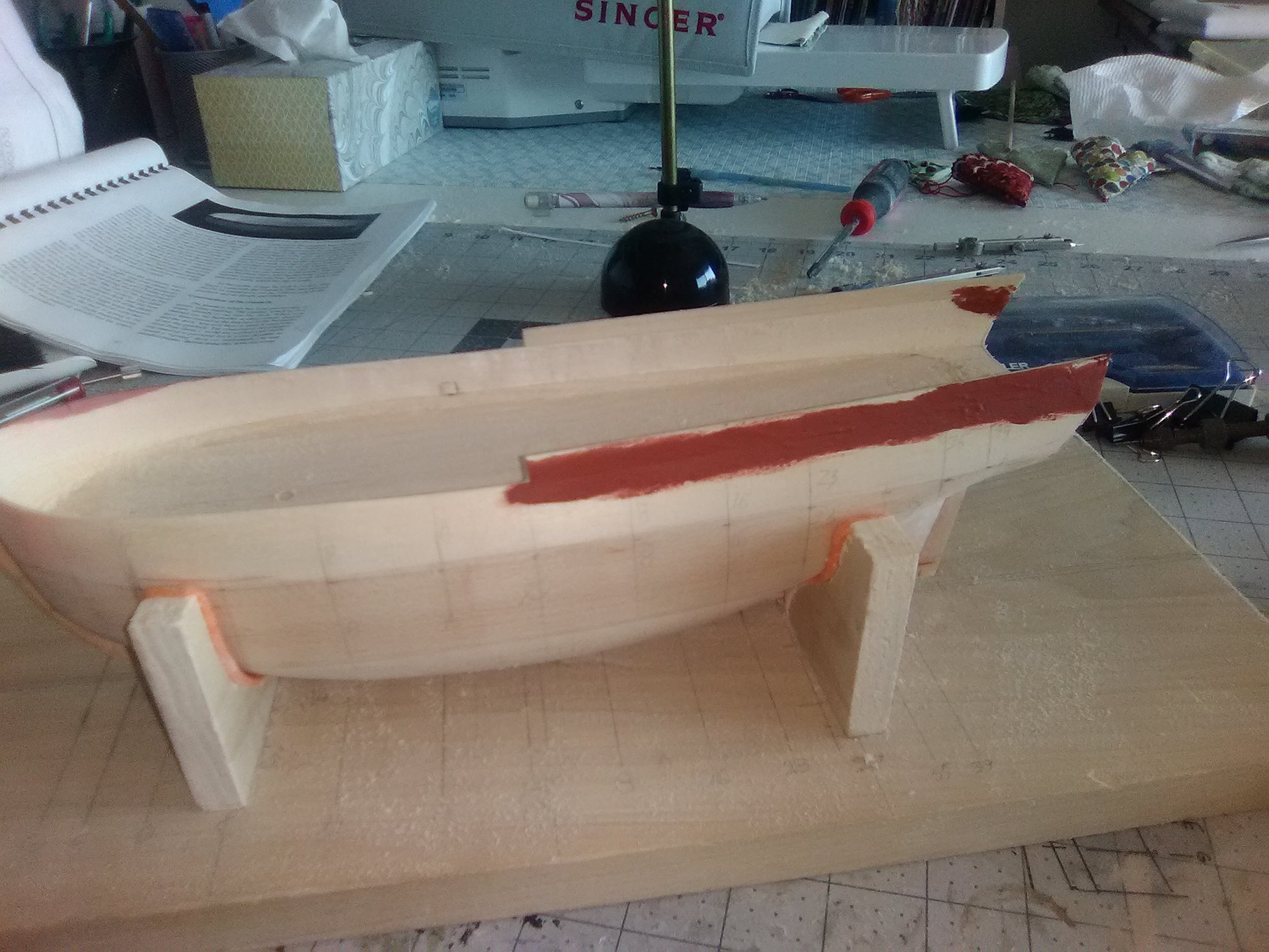
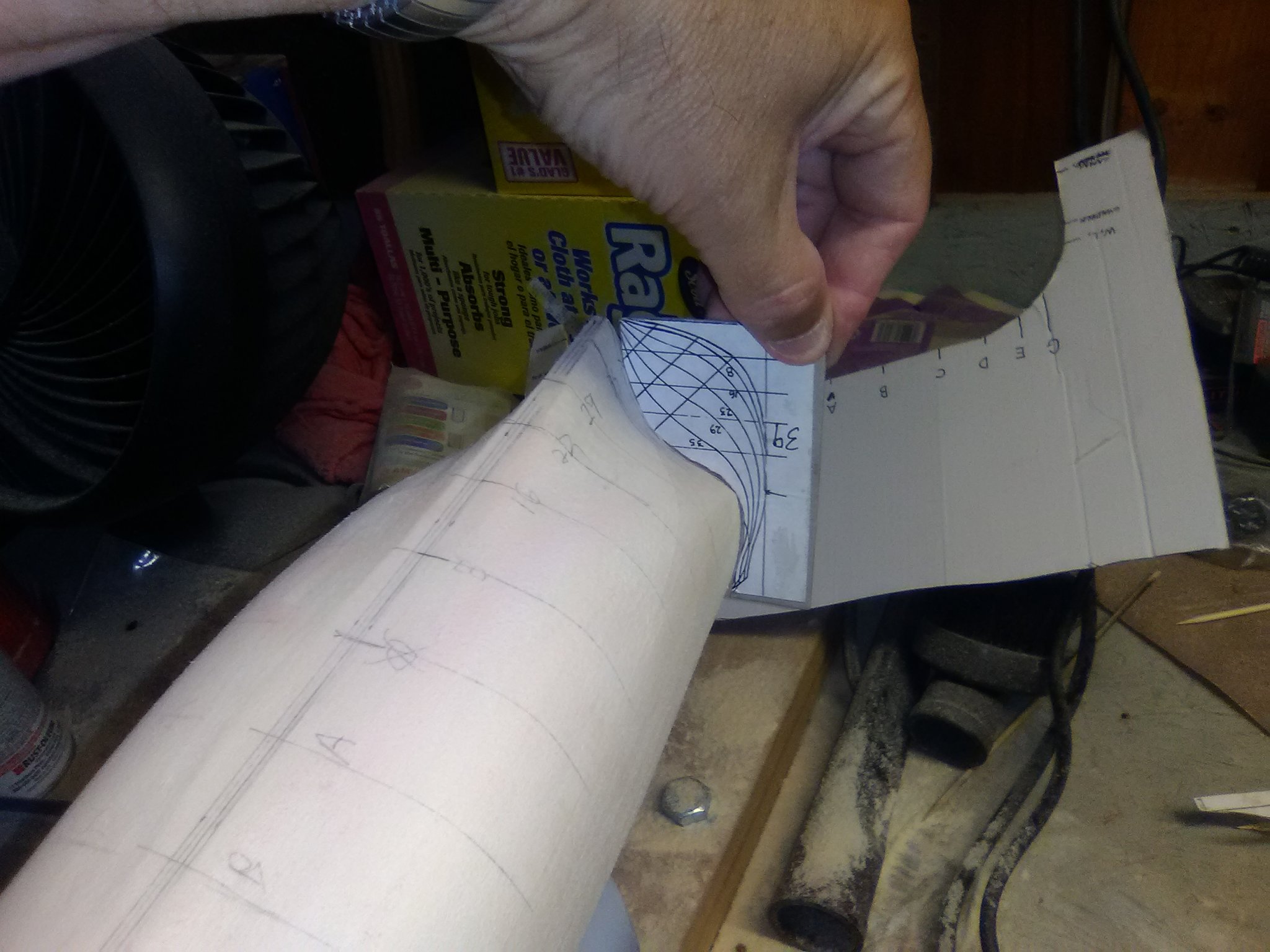
Progress has been pretty slow for the last couple of weeks, mainly because it has been so hot around here that the only time I can go outside to do some sanding is right after sunrise - the same time I need to take care of outside chores. So over the last month I’ve only been able to put in maybe 3-4 hours of sanding time but that has been enough to get the hull in rough shape. This photo illustrates a problem I have been having with this type of hull. Up until now all of my solid hull builds have been steel-hull ships whose shapes are pretty simple - a little flair near the bow and some rounding around the stern. On a 18th century ship like this one they had a fair amount of tumblehome along the upper hull - something I’ve not had to think about before so it took me a while to figure out that the half-hull templates may not fit perfectly until after I sand some tumblehome along the bulwarks which I’m not ready to do at this point so I just have to trust it will work out a little further down the road:

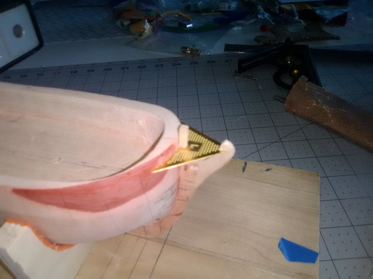
One problem I had is that the shape of the transom is a little short of what it should be:
I added some planking material to lengthen it a bit and also to sharpen the demarcation line between the transom and the counter:
Once I trimmed up the new wood it is a better fit.

How the surface of the new wood looks doesn’t really matter since almost all of it will be removed shortly (the area between the pencil marks), leaving the aft end of the hull looking like the bed of a pickup truck with the gate removed:

Next steps will be to remove the big plug of wood from the transom area and then add the sternpost, stem and keel.
-
Wonderful workmanship.
Do you think the kit could be built just using hand tools and a Dremel or does it need shop tools like power saws, drill press, etc?
Please post some photos and/or videos when you get her waterborne.
Once again, great job!!!!
-
-
-
-
Gary, no personal connection. Based on the photo in BlueJacket's catalog I assumed the kit only had the type of air search radar used on about half of the FRAMS so that narrowed my search down a bit (I found out they supply both types of radars). I remember a sailor on my first ship had served on the Basilone and thought she was a great ship, and her namesake was a great hero so I went with her. An added plus was that her former shipmate's website had a ton of photos which helped with the detailing.
-
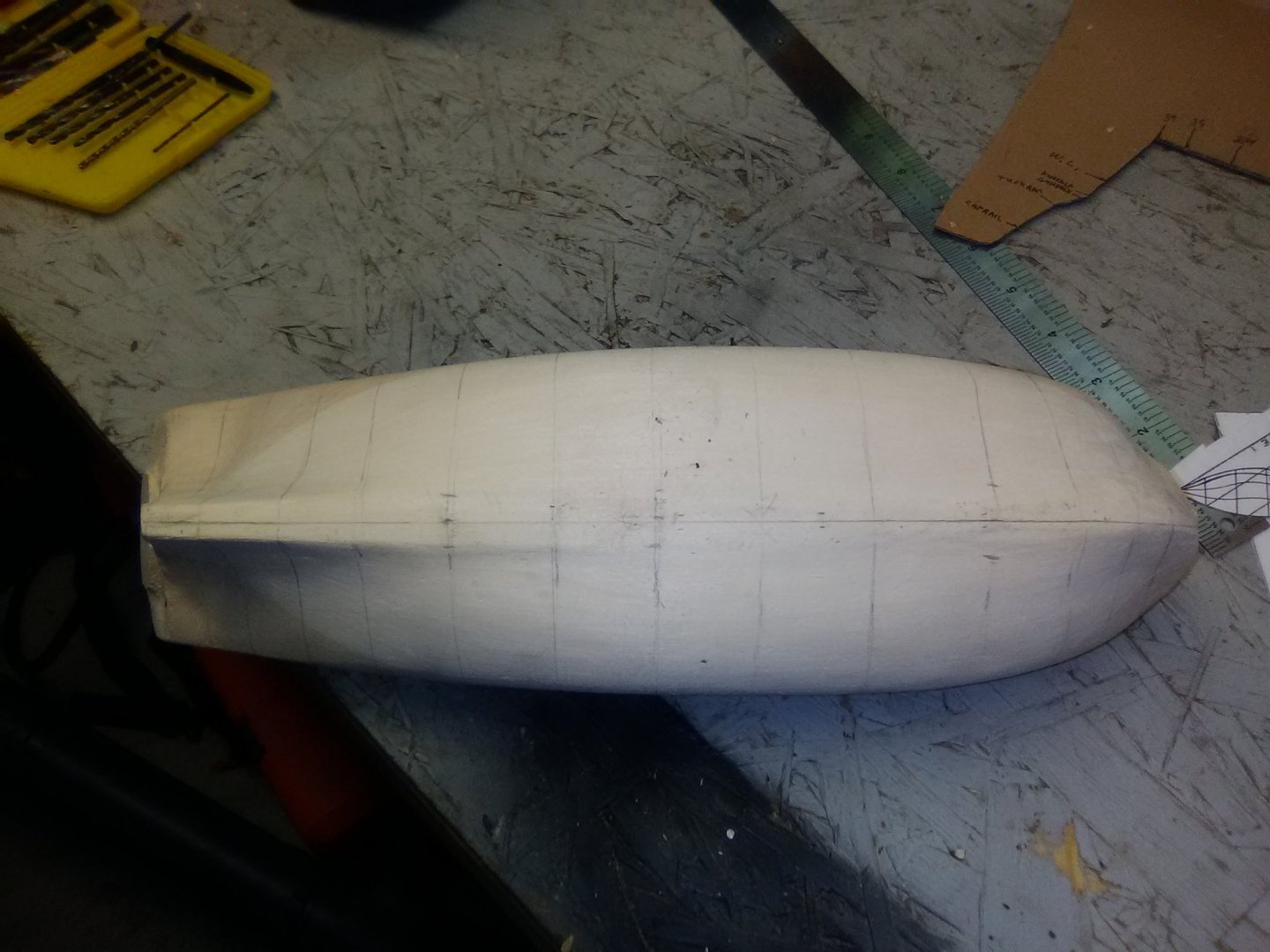
The initial shaping of the hull is coming along pretty well, a small hull like this one is much easier to shape than a 2 or 3-footer.
The are my go-to tools for this stage of the work. The mouse sander works well on most of the hull surface, the flap sanding wheel works well around the stern post, and the half-round file is needed to handle the stern knuckle and transom area.
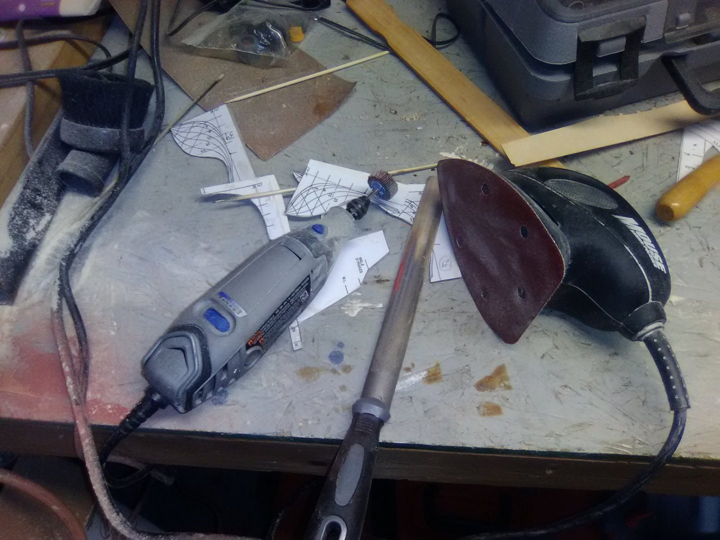
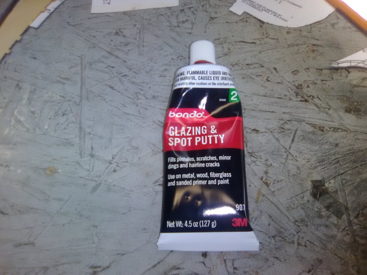
For those places where I get carried away this stuff works wonders as a filler. It comes from auto parts stores. It does not need to be mixed with a hardener, it dries quickly adheres well to the wood and sands easily. The only thing to keep in mind is that if you need to make it more than about 1/16" thick it is better to put on multiple layers -letting the previous ones dry. It needs air to dry and harden well.
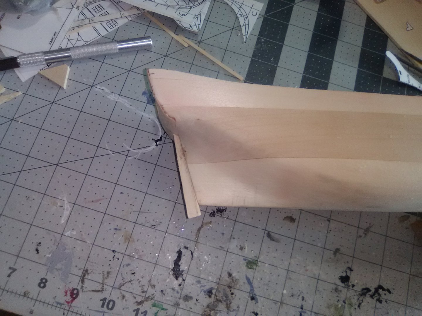
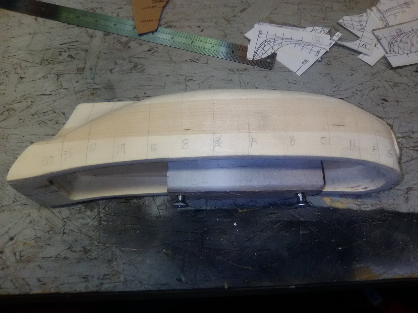
The bow and stern are at their final shapes:

The overall length is in accordance with the plans:
And the shaping of the hull is coming along at the individual stations (more work to though).

-
Gary,
I'm going to be following along because this is such a nice looking ship. I enjoyed your build log of the Fannie G and learned a lot that will help me with my (just started) build of BlueJacket's ALFRED kit.
At the rate you move along you will be done with this one before I've even finished shaping the hull!
-
It does come with planking, albeit a bit on the small size (.02 X 3/32) because of the scale and yes I would like to plank it, ideally the whole hull, including the inside of the bulwarks, but if that is too ambitious I'll just do the wales on up.
- Bill Morrison and mtaylor
-
2
-
David - Glad to have you following along. I may need your advice when it comes to planking. That is an impressive list of completed models, I'm sure a solid hull build would be easy for you.
Kevin - that is an incredible build of your St Nectan trawler! If I were crazy enough to try something at that scale I would have to go for something 8-10 ft long so I could sleep in it after my wife threw it, and me, out of house.
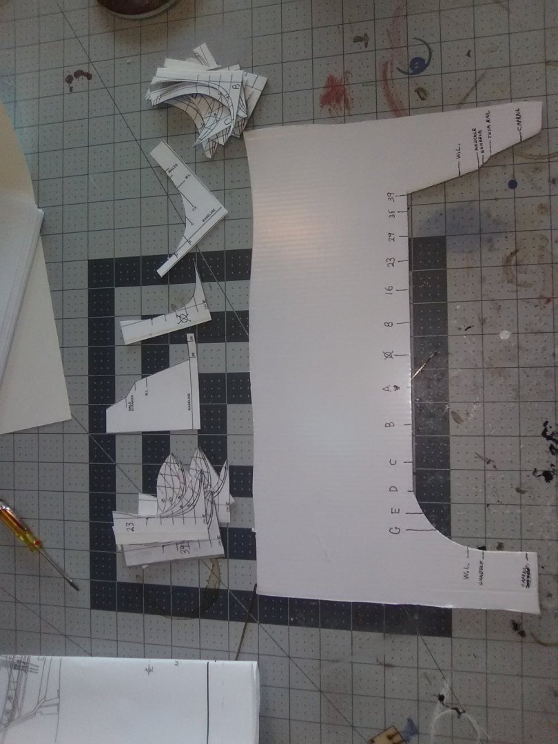
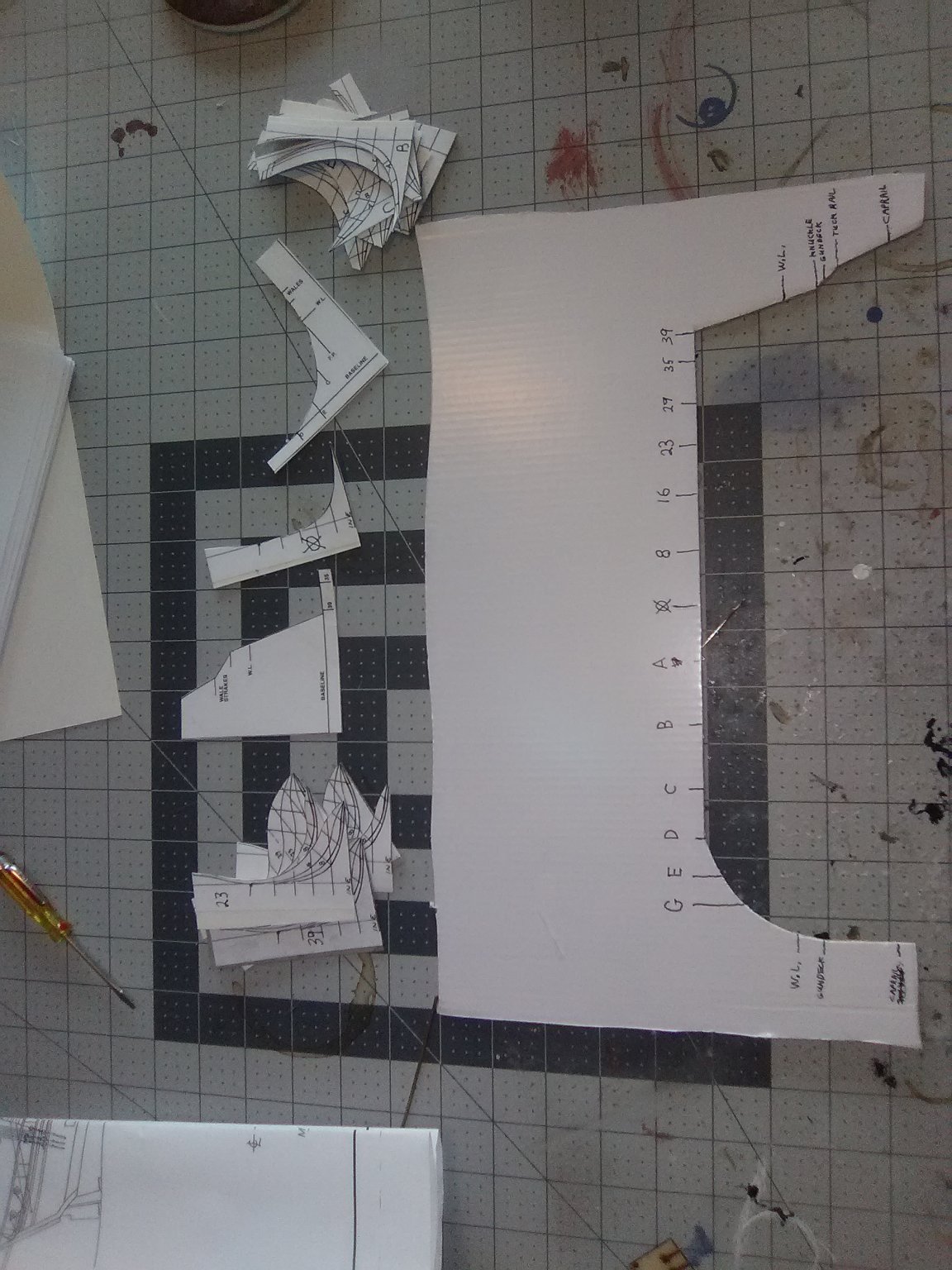
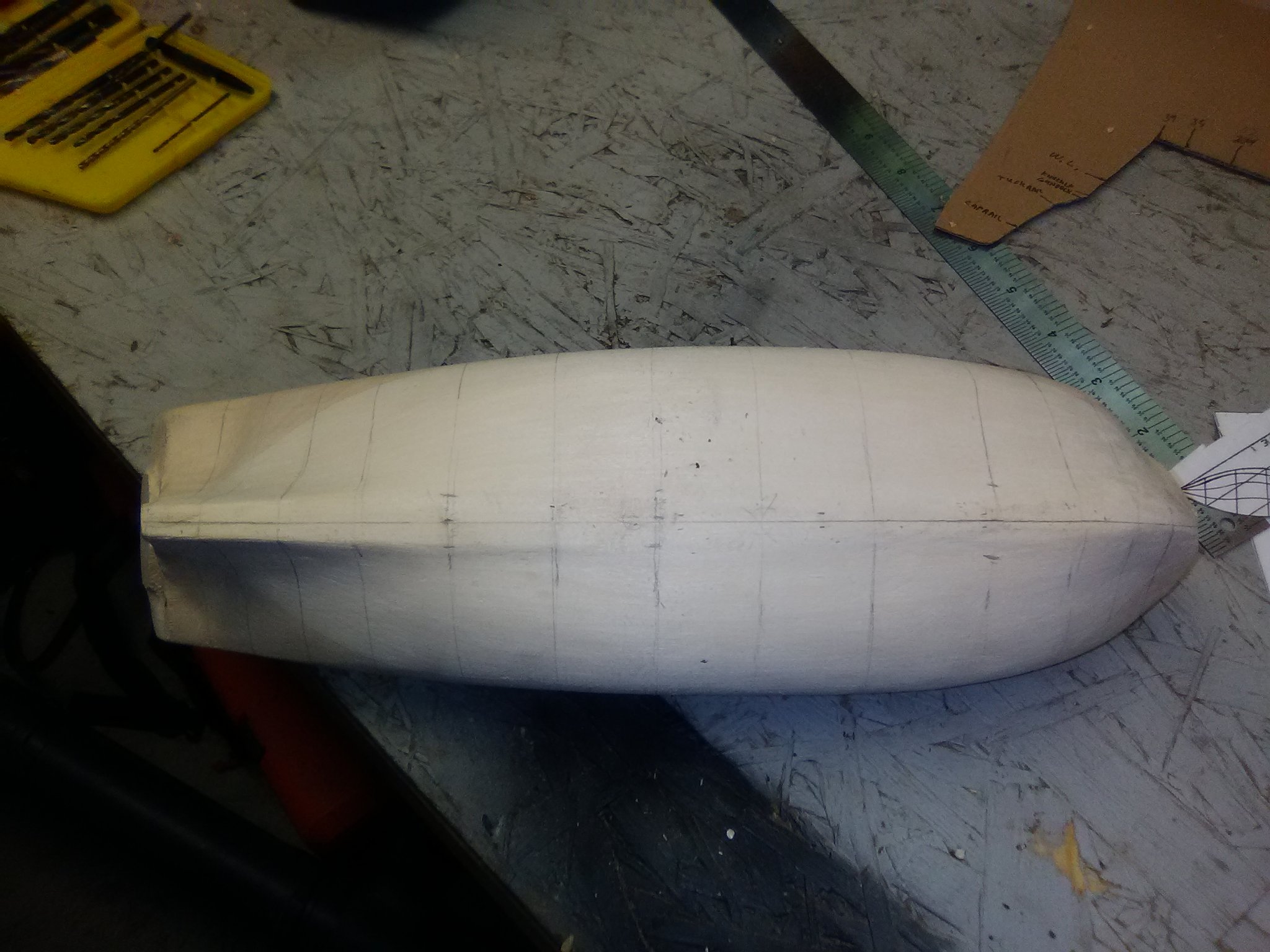
I finished up the preliminary stuff that has to be done prior to making sawdust. The half hull lines have been cut out and pasted to cardboard, as have templates to shape the bow and stern and an overall template from the side view on the plans. There are some discrepancies between the bow/stern templates and the overall template, enough that to get them to fit at their specified station lines I would have to remove a lot of wood in some areas and add it in others. I decided to go with the overall plan and just use the bow & stern templates to guide shaping but not length on the model.
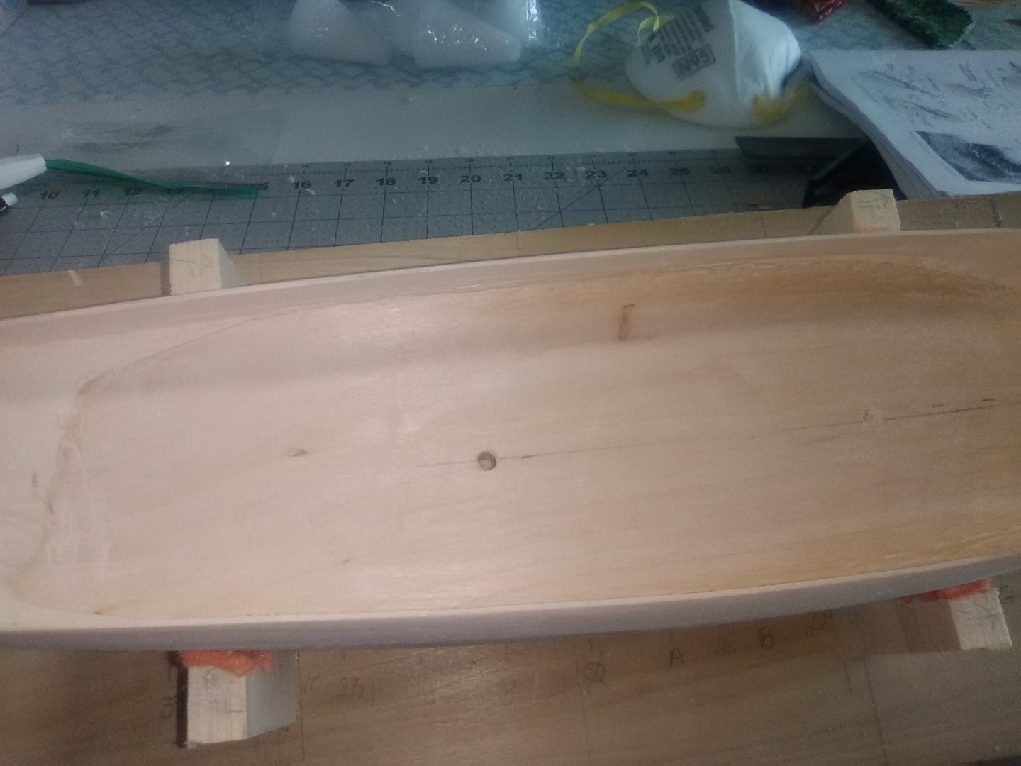
The station lines, waterline, and caprail locations have been marked on the hull, as has the centerline (always more guesswork than technique for me but It looks OK).
I'm going to have to build up the stern area with Bondo in order to get the proper shape and then it will be time to break out the electric sander and get to work.
Note from further along in the build: As you shape the hull DO NOT sand the top of the bulwarks - after thinning my bulwarks I did a lot of measuring for the placement of the gunports and found that the height of the bulwarks, with the exception of the last 2-3 inches back aft, is spot on for their final height above the gun deck so my advice is to leave the tops alone at this point.
- mtaylor, etubino and Bill Morrison
-
3


Red Baron by CTYankee - BlueJacket Shipcrafters - 3/8" scale - lobster boat - first build
in - Kit build logs for subjects built from 1901 - Present Day
Posted
One trick for filling small cracks is to use white (or Elmer's) glue. It has the strange property that if you are filling in a small crack or gap, say between a deck and a vertical bulkhead, the glue not only fills the gap but it tricks the eye into not even seeing the filled crack even though the glue dries transparent. That has really saved me a couple of times where I had 2 surfaces painted different colors that would have been tough to tape off and paint - white glue made the problem invisible1