


wefalck
-
Posts
6,648 -
Joined
-
Last visited
Content Type
Profiles
Forums
Gallery
Events
Everything posted by wefalck
-
 What operating system are you on and what kind of software do you have at your disposal? I am on MacOS and have Adobe Photoshop Elements. With the latter I can open PNG-files and then save them as JPEGs - quick and easy. It should also work with Apple's own 'Preview' software. I gather there are several other image processing software packages on MS Windows that do the same job.
 -
For some people, building a model is mainly the means to consolidate in a tangible form the results or their research. So it is more about the way than the actual product at the end, although this can also be an aesthetic pleasure, of course. Other people build models to exercise and demonstrate their skills and other just want something pretty on their shelves ...
-
There is a bit of a scale gap in books and other instructions on the practicalities of realistic ship models. For instance, Lloyd McCaffery provides ideas for very small scales, based on wire, in his book. There are the old-time classics, such as Underhill, but they typically are aimed at a scale of 1/48 or perhaps down to 1/64 or so. In the range of 1/72 down to 1/200 there isn't anything specifically in bookform, as far as I am aware. If you are interested in a tour-de-force of absolutely detailed, down to all the splicing and serving, rigging example in 1/48 including all the historical research that goes with it, have a look at @archjofo's log on LA CREOLE (we have been pushing him to write up his work in a more permanent form, but this is a lot of work). Another example, but in 1/96 scale is @dafi's HMS VICTORY. At this scale, he has to make already simplifications and describes them very well, including rope-making. At smaller scales the materials are a limiting factor. About the thinnest material for rope you can get is 16/0 fly-tying thread and Alterfil L400 sewing thread. Below that you will have to resort to wire.
- 2,699 replies
-
- 3
-

-
- heller
- soleil royal
- (and 9 more)
-
Pulled the Trigger == Lathe coming
wefalck replied to kgstakes's topic in Modeling tools and Workshop Equipment
Perhaps one should note an important difference between the Taig and the Sherline: in the Taig the longitudinal slide is moved by a rack-and-pinion-drive, which is why it has the handwheel in front of the apron, while in the Sherline it is driven by a leadscrew and a full nut under the apron, which is why there is the handwheel at the end of the bed. This means, that the Taig cannot cut screws without a modifaction that adds a leadscrew. Not a difficult modification and I believe, there are some examples for it on the Internet. Of course, additional modifications are needed by adding a banjo and changewheels, but these have to bought separately for the Sherline as well. The big disadvantage of the the rack-and-pinion-drive is that its position is less accurate than that by leadscrew and the 'feel' is less 'positive', depending on how accurate the rack and pinion match and how well the position is adjusted. On 'big' engine lathes one has a combination of both types of drives and the nut under the apron is designed as 'split-nut', which allows to disengage the leadscrew with a lever, so that the slide can be moved faster with the rack-and-pinion-drive. -
I gather these were designed, before so much plastic was floating around the oceans ... actually a jelly-fish can have the same effect and is quite natural ... There may be also a an outlet for the sewage. Today you have to have buffer tanks that are then emptied when at sea ... I have not so nice mermories of having to clean out the blocked sewage system on a sailboat.
-
To be honest, I have no clue, why the pictures where converted to PNG. They were re-uploaded to these posts in the same way as the other pictures. Also, there appear magically to images of the plug at the end of the post, that didn't put there and I don't manage to delete them ...
-
These grilles are probably cooling water intakes for the engine or perhaps for an a/c, if they have one ?
-
My newest Challenge
wefalck replied to James Flynn's topic in Building, Framing, Planking and plating a ships hull and deck
I think @JacquesCousteau framed very well our sentiments in that respect. I have something like 45 years of scratch-building under my belt and a pretty well kitted out (mechanical) workshop, but I am slow builder. While I think a project, such as yours would be a great ambitions, considering that I spent already 18 years on a modest 1870s gun-boat and that I am approaching fast 70 years of age, I made a life-decision and that is to go for small ships that I can complete within a reasonable time-frame. I decided to put a lot of details in something smallish, rather than to build something big, where I would be confounded just by the number of repetitive details that I would have to make. OK, this is my personal philosophy as model builder. Before tackling a project as you envisaged, it would be also good think about what kind of workshop space you have, what your workshop kit looks like and what investments may be needed to bring it up to a suitable level. The next tough question is also that of the skill and true patience level. Personally, I don't like the concept of 'beginner's' models. That's something invented by the kit industry. I you are an accomplished artisan or have built other types of models from scratch, there is no reaons why you shouldn't tackle even an ambitious ship successfully. Of course, if you have to learn the necessary woodworking and metalworking skills first, the situation may be different. One can learn everything, provided one has the necessary patience. I personally think, that people do not fail because they have to left thumbs, but because they do not have the patience to use the rest of their hands. I think you are trying to pack to many ambitions into one model. Yes, everyone of us wants to build the life-time model, but there may be so many practical problems that this easily can end up in a life-time frustration. Break down your ambition into several smaller ones. Build a smaller-scale model of one of those mid-19th century wooden anachronisms, build an individual gun station with all the details, even remotely controlled functions, etc. and you will have a reasonable chance to be proud of it ... -
My newest Challenge
wefalck replied to James Flynn's topic in Building, Framing, Planking and plating a ships hull and deck
You don't do it small, don't you? You mean the one of 1837? No, I don't have any plans. The Smithonian Institution in Washington would be a source, but others here may be better informed about USN ships. -
My newest Challenge
wefalck replied to James Flynn's topic in Building, Framing, Planking and plating a ships hull and deck
I think this is a wise decision, avoiding frustration and an abandoned project. If you google for 'Atlas du Genie Maritime', you will actually find hundreds of free(!) plans from the French archives of ships large and small, complex and simple. I can't point you right now to a contents list. Unfortunately, due to being hacked, the French naval archives have taken all their digitised plans off the Web a few years ago. However, if you find something that interests you, send me the link you found to the small plans and I can send you the full-size plan, that I had downloaded before the archive went off the air. Another source of free plans is the Maritime Museum in Greenwich (UK): https://www.rmg.co.uk/collections A third source are archives of the former Danish Naval Yard in Copenhagen (Denmark) - great resource, but time-consuming to navigate on the Web: https://arkivalieronline.rigsarkivet.dk/da/other/index-creator/40/3353816/17149179 Keep in mind that these are copies of original ships plans and are not processed/redrawn for model building. -
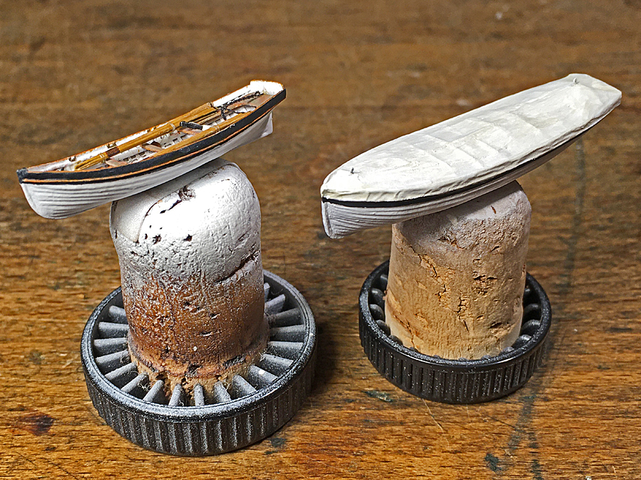
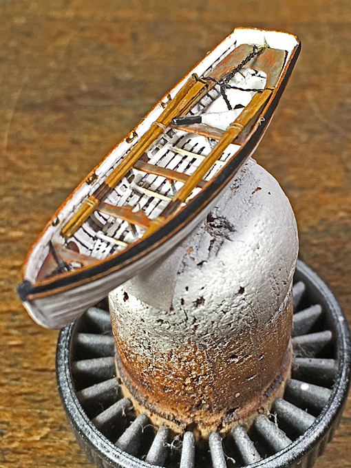
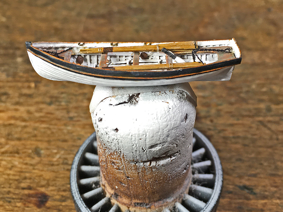
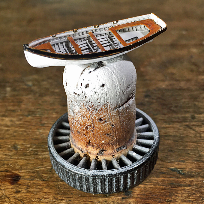
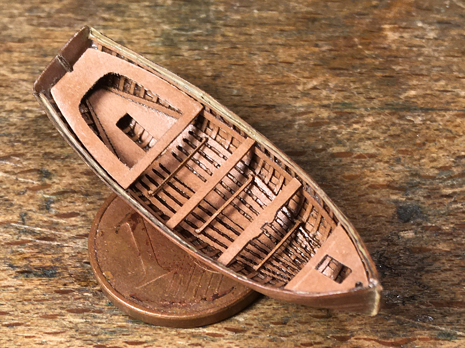
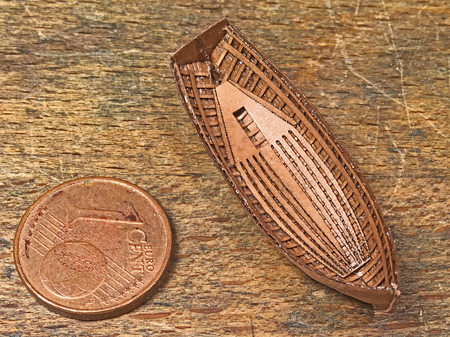
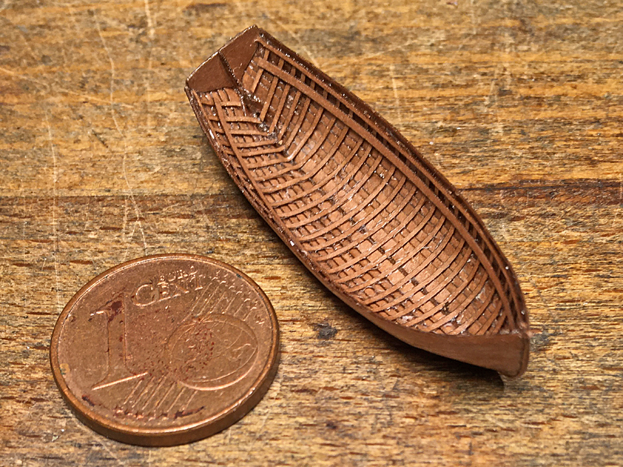
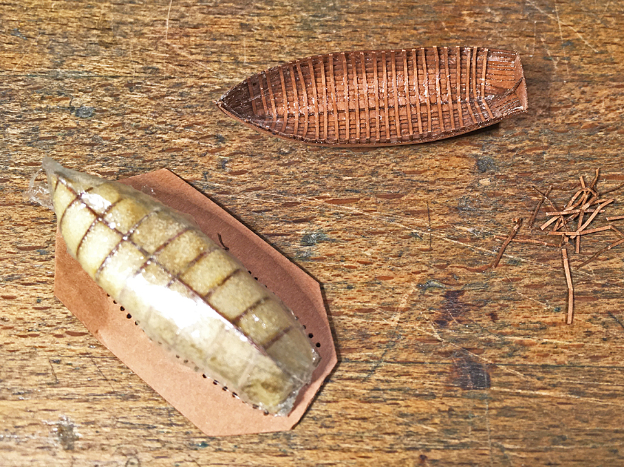
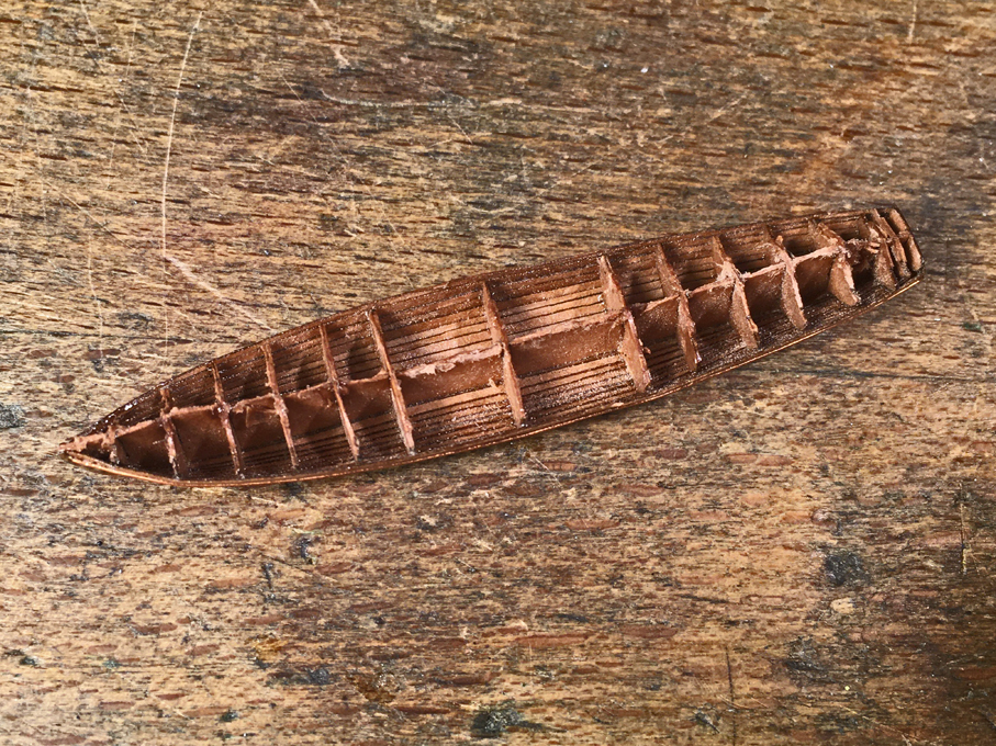
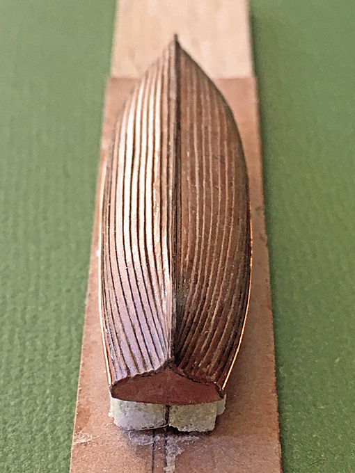
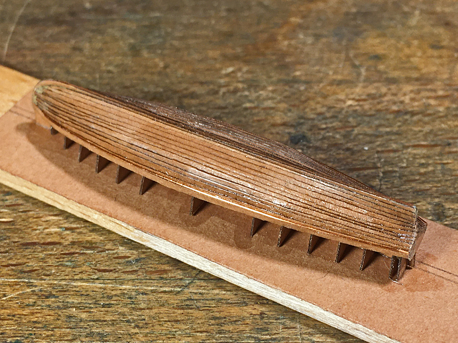
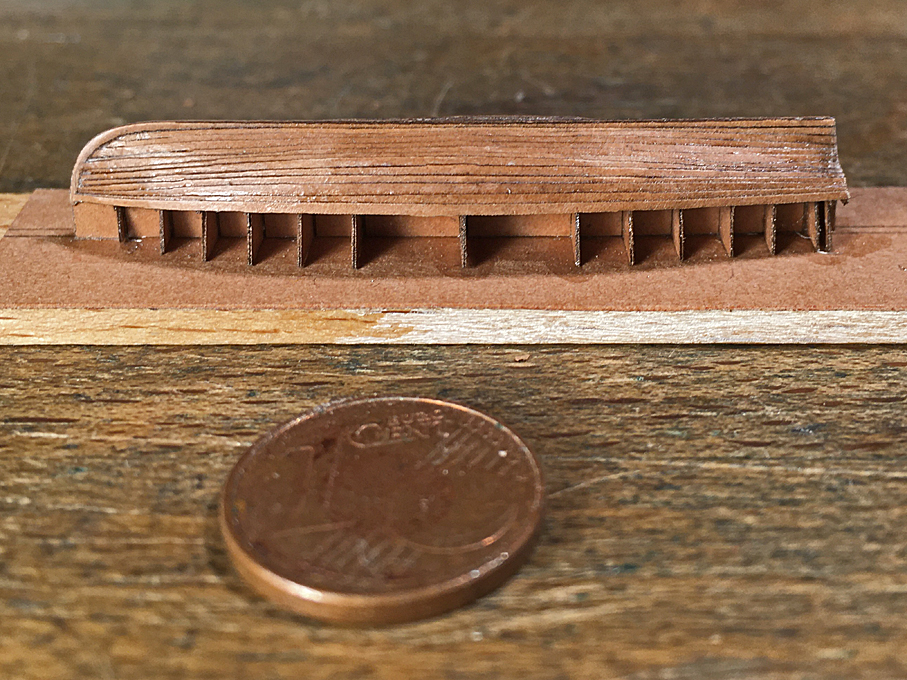
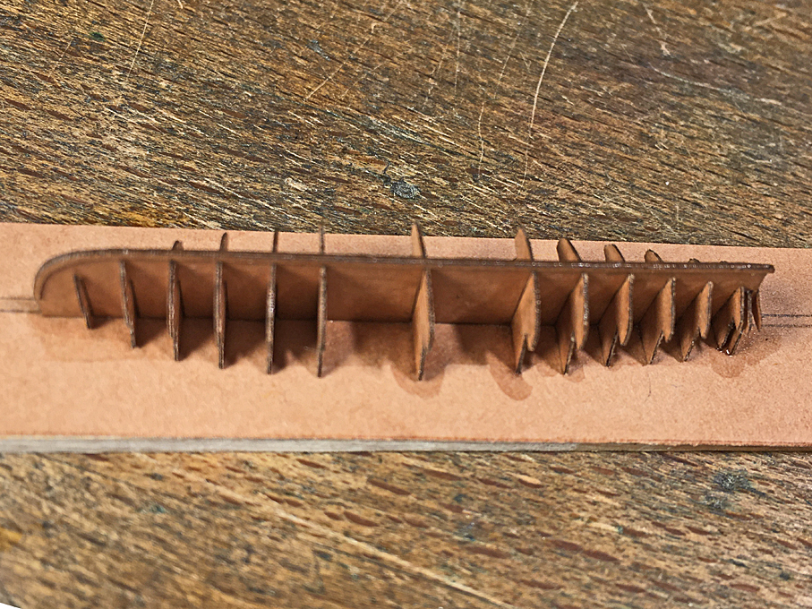
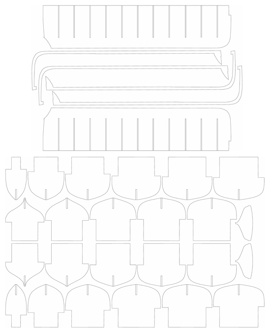
Building fully framed open boats The procedure is in principle similar to that of a boat that is covered. However, the bulkheads have to be drawn to the inside of the (bent) frames. The plug is built up in the same way as above. The plug built up from hard foam is then covered in a thin layer of automotive putty, which is carefully sanded down to the laser-cut templates. In order to prevent the structural parts of the boat from sticking to the plug, it is covered in cling-film that is drawn tightly over it, avoiding folds and creases. This plug is mounted to a baseboard of two layers of paper laminated together with varnish. This baseboard has rectangular holes for holding the bent frames in place, which are cut with the aid of the laser-cutter. The baseboard is glued to a piece of wood that is a bit smaller than the inboard profile of the boat, which allows it to be held in a vice etc. to ease further manipulation. It is important to remember, that this method of construction only works, if the boat has no tumble-home. Otherwise, it will not be possible to remove the hull from the plug. For boats with tumble-home, one would have to carve a solid former from interlocking pieces that can be released successively and lifted out of the hull. Laser-cutting templates for the formers and main structural components of a jolly-boat. Plug for the POF construction The bent frames are laser-cut strips of paper of the appropriate width. To achieve scale thickness, doubling may be required. The strips are bent around the plug, inserted into the rectangular holes, aligned carefully, and then cemented to the baseboard with varnish. If neede, they can be tied down in addition onto the plug with a length of wire that is tightened by twisting. The backbone of the jolly-boat The design of the stempost-keel-sternpost part is somewhat different from the previous construction. It is basically in two parts. One part is the part inside the boat and the other part is the one that is visible outside. The separation-line is basically the rabbet-line. The photographs give an idea of this. The actual outboard stempost-keel piece will be added later, after the planking. The interior part will be glued onto the frames now and the transom added. It should be noted that there will be likely a couple of cant-frames that but against the keel/stem, rather than running under it. In consequence, these can only be installed after the planking of the hull is completed. The framed structure One may have noticed that this is the reverse construction order compared to the full-scale practice. A traditional clinker-built boat would be built over a couple of templates, with the planks going in first and the frames bent in afterwards – the ‘shell-first’ principle. I prefer the described method, because having the frames in place provides more glue surfaces than just the plank edges and thus makes for a stronger shell, when removing it from the plug. The garboard-plank installed I don’t want to hide the fact, the gluing and coercing down the planks here is a bit more difficult than when gluing them to the solid plug. As on any clinker-built boat, the garboard-plank is the most difficult to install due to its torsion and being curved in all planes. Here it is no exception. It needs a fair amount of coercion. Planking, of course, proceeds in parallel on both side of the hull in order to ensure symmetry. Planked-up starboard side of a jolly-boat with the stempost-keel-combination also in place After the planks are on, the outside part of the stempost-keel-combination is installed. With this one cannot really see that is was no real rabbet into which the planks run. Looking down onto the planking; the overall length of the boat is 36 mm (just under 1.5") The next step is to cut the excess length of the bent frames and to cautiously rock the hull in order to release it from the plug. The frames are then trimmed back to the sheer line. If part of the design, the additional (cant)frames will have to go in now, before the further fitting out can begin. The result is a quite strong hull with the typical exterior and interior look of a clinker-built boat. Cutting the extended frames with micro-scissors Hull begins to detach from the plug Hull successfully taken off the plug Next go in the gunwales and the inwales on which the seats rest, all laser-cut strips of paper, doubled where needed and lacquered into place. Now the hull is given a coat of varnish and cautiously rubbed down with steel wool. Any imperfection visible can be touched up with putty, although it is likely, that more become visible once the first coat of paint has been applied to the hull. Shell with gunwales and inwales Most open boats have floorboards. These may be arranged in many different ways, but often are panels of several boards, which can be lifted out to give access to the bilge. Aligning these properly can be tricky and it may be a good idea to design them as a single unit, when the joining parts can be hidden under the seats etc. Floorboards installed in the hull At this small scale it is difficult to build precisely to the drawings, so that stern-sheets, seats, and other pieces may not fit exactly as drawn. This requires a bit of trial and error, and perhaps re-drawing for laser-cutting. Still a bit of sanding may be required for a perfect fit. Sanding paper is not that much fun, but re-soaking it in lacquer after a few strokes with a diamond-file keeps fraying under control. Stern-sheets, rowing seats and bow-platform installed The remaining fitting out depends on the features of the prototype. There may be foot-rests for the rowers, pillars under seats, covering boards over the sheer-strake, strengthening pieces where the thole pins are inserted, reinforcements of the washing-strake around row-locks, mast-steps, etc. All these can be laser-cut pieces. There exact size and shape is best taken off the hull and drawings produced accordingly to control the laser-cutter. They are lacquered into place. Depending on whether the iron hardware in the boats is going to be painted it can be installed now or left after the main part of painting has been done. The sequence of painting really depends on the kind of prototype. Painted model of a jolly-boat on an ordinary port-wine cork There will be various items of loose equipment such as the oars, rudders, fenders, a water-cask etc. that also can be produced with the aid of the laser-cutter. Painted model of a jolly-boat on an ordinary port-wine cork The oars can also be built up from laser-cut parts. It may need a bit of trial and error to get the right shape and dimensions, as the laser-cutter can be somewhat unpredictable with such small parts. Each oar is lacquered together from three layers to build up their shape. The round of the shaft was built up with more varnish and sanded to shape using a diamond file. More varnish was applied before the paper showed signs of fraying. Template for laser-cutting three-part Oars Fully kitted-out jolly-boat in 1/160 scale. The above lines are only intended to outline the principle of construction. Each boat-type is different and has different elements of construction. While the description concerned boats with bent frames, the same principle could be used for boats with sawn frames. Again, the plug (if such was used) would need to be moulded to the inside of the now wider frames. Each frame needs to be cut out in multiple copies to build up the necessary thickness. Of course, if one has a stronger laser-cutter, one can use thicker paper/cardboard. The construction then is essentially that of POF and several commercial kits for such boats (albeit at a somewhat larger scale) are already on the market. Comparison of a fully open and a covered boat in 1/160 scale THE END


- 13 replies
-
- 14
-

-
-

-
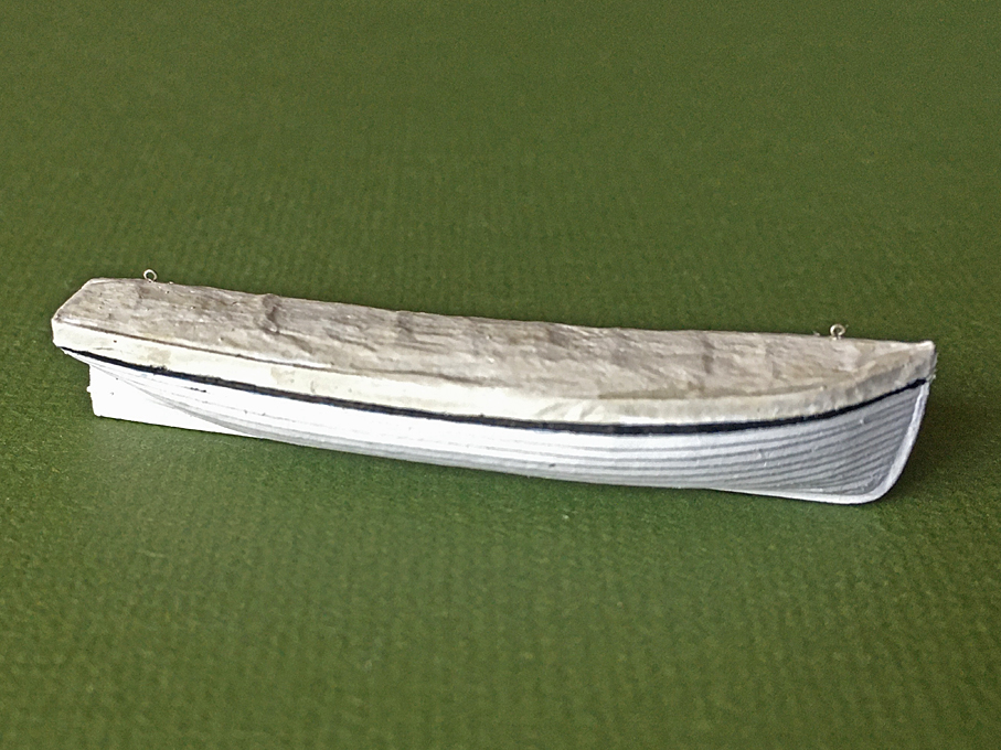
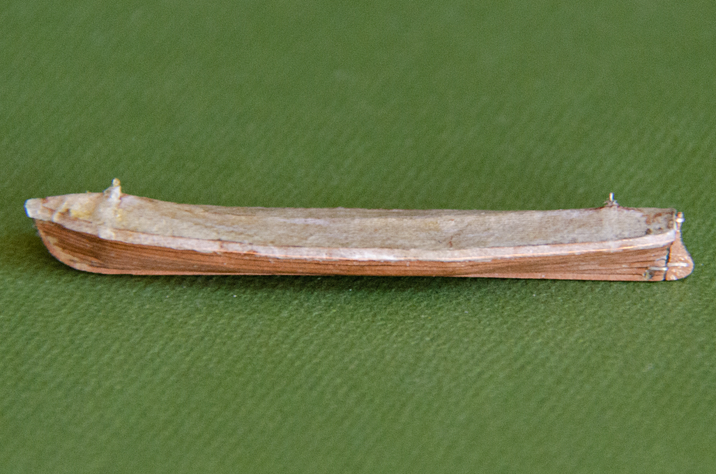
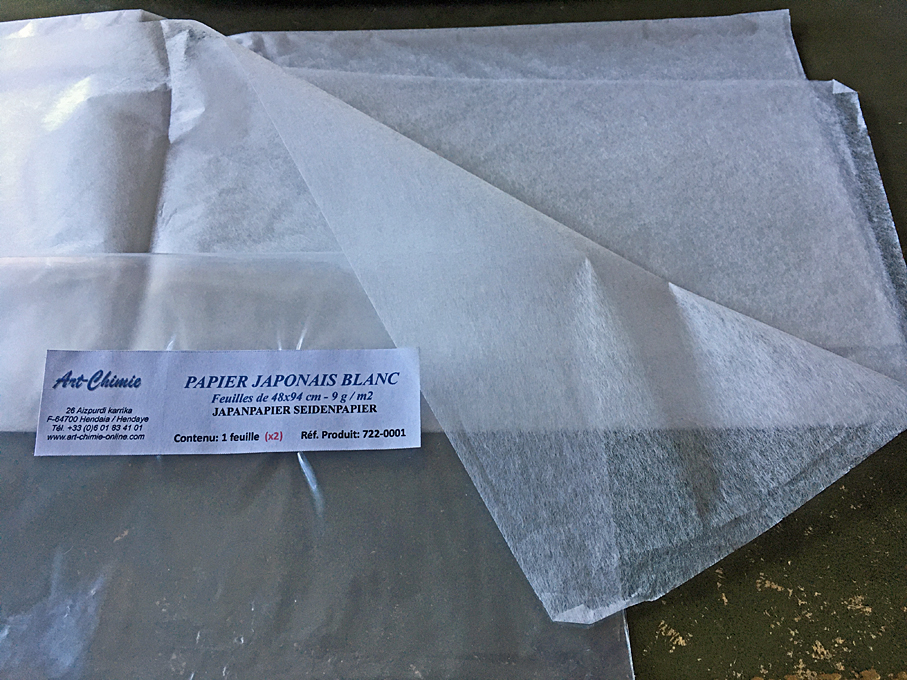
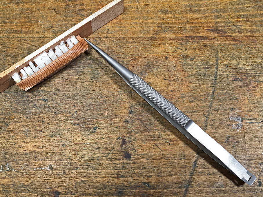
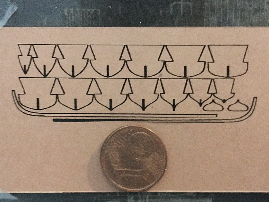
Continuation ... Planking of a gig completed Once the planking is completed, the excess material at the stem and stern/transom can be trimmed off flush. For this so-called cutting-tweezers as used by watchmakers to shorten watch springs are a very handy tool. The planked hull can now be given a coat of varnish to consolidate and further stabilise it. It then is rubbed down cautiously with fine (0000) steel-wool to smooth it. If needed, imperfections can be touched up with putty and sanded. The next step is to glue the combination of keel and stem-post into place using the same varnish. This was laminated from several copies of the same laser-cut shape to achieve the necessary thickness. Any gaps can be filled with putty. Many boats are fitted with rubbing strakes. Depending on how they look, they can be made from either very narrow laser-cut strips of paper or from thin wire that glued down with varnish. Rubbing strake from 0.2 mm copper-wire installed on a gig This basically completes the boat construction and it is ready to be cut from the building base. The next steps depend on how the prototype is arranged, i.e. whether it is suspended from davits, stands in chocks, or may be is placed upside down on a boat-skid. The bulkheads have to be cut down and the backbone be trimmed to a line that e,g, would be followed by the tarpaulin cover or that of the gunwale. The completed planking on a cutter If there are hoisting chains fore and aft to which the falls of the boat-davits will be hooked, only the top ring would be protruding from the boat-cover. This chain can simulated using a twisted-together piece of coper-wire of suitable thickness. The wire will be hooked into a bulkhead and glued down with varnish. Gig cut free from the building base (note: here the hull was not filled with foam) Completed cutter cut free from the building board Boats slung from davits or sitting upright in chocks are exposed to the elements and, therefore, often covered with a tarpaulin. The designs for such covers vary, but typically triangular pieces of canvass are sewn to the edges to which lanyards are spliced to tie the cover down. Other designs may use a draw-string in a hollow seam that goes all around the boat below the rubbing strake – much like purse-strings. Very light-weight Japanese silk-paper for tarpaulins, sails etc. Gig with simulated cover The boat-cover is cut to the rough shape from a piece of thin silk-paper, draped over the boat and soaked in sanding filler. It is then smoothed down over the edges and down to the rubbing strake. Once dry the paper is cautiously cut back to the rubbing-strake with a new scalpel-blade. Now, if necessary, the canvass triangles can be added. The draw strings are only added after painting. Rudder-pintles are made from short pieces of copper-wire or appropriate diameter and the respective bands are simulated by flattened copper-wire. All parts are cemented in place with varnish. The boat is now ready for painting. The procedure depends on the colour scheme, of course. As the boat-covers are typically off-white (i.e. oiled canvas), it may make sense to give the whole boat a coat of white paint with the airbrush. This kind of basecoat (though technically not needed) allows to better see imperfections, that may need to be fixed before final painting. To be honest the results can be quite sobering: all the imperfections that were not visible in the ‘raw’ state now begin to stick out. Any jagged edges from the laser cutting that seem to disappear under the varnish become now rather visible. So some more filing and putty-work may be required. It is important to remember that we are talking about small boats, perhaps two to four centimetres long with a beam of barely one centimetre … Painted cutter in 1/160 scale One should add, that laser-cut parts can also be used as templates (when drawn to the outside of the planking) for the frame-stations when carving solid hulls from wood to make carvel-built boats. They could be completed then with the same kind of laser-cut stem-keel-piece. Trying to build carvel-hulls with laser-cut paper planking may not be so successful, as paper does not sand very well. However, a good amount of putty could help here and at the bottom line may be quicker than carving with frequent checking of the shape against templates. To be continued …

- 13 replies
-
- 13
-
-
-
@tkay11 Sorry for the missing pictures initially. Don't know what happened to them, as they appeared while I was composing the post. Now corrected! @shipman My original pictures are JPGs and uploaded as such. However, it seems that the MSW forum software converts these into PNGs so that their size can be automatically adjusted to the width of the screen. I have no control over that.
-
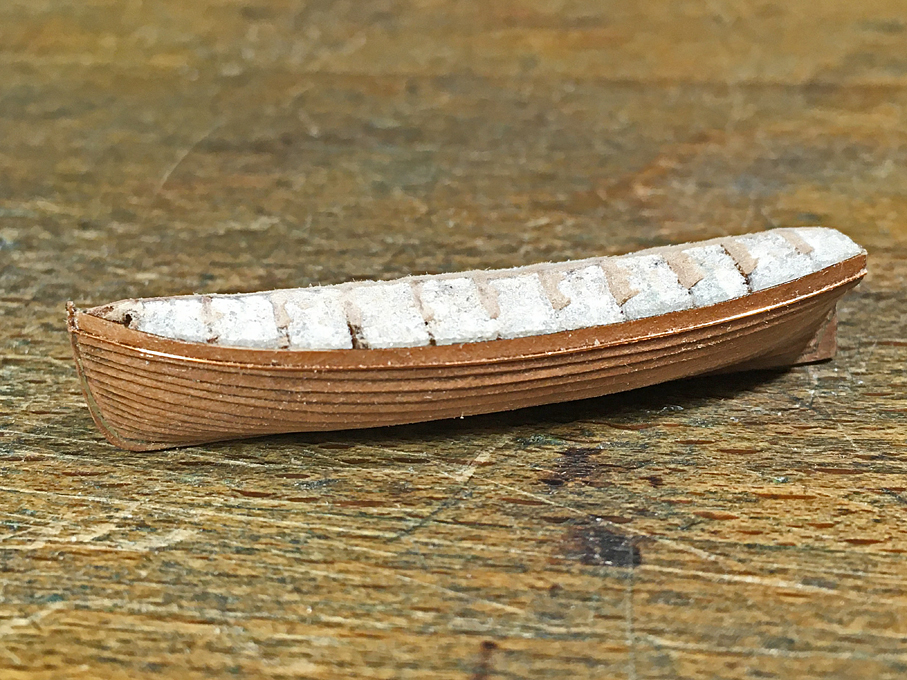
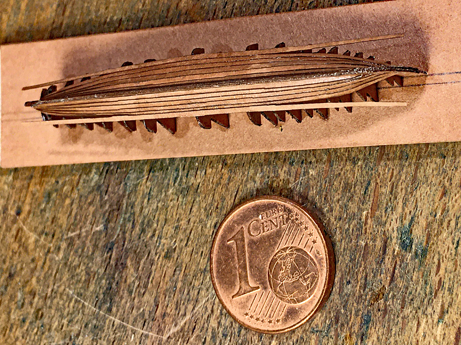
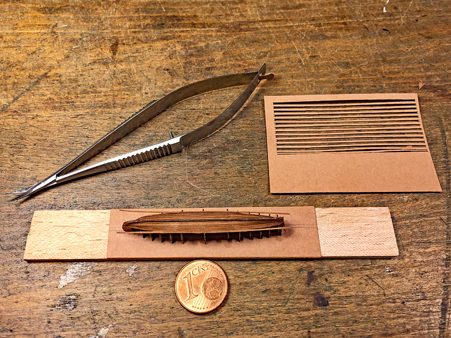
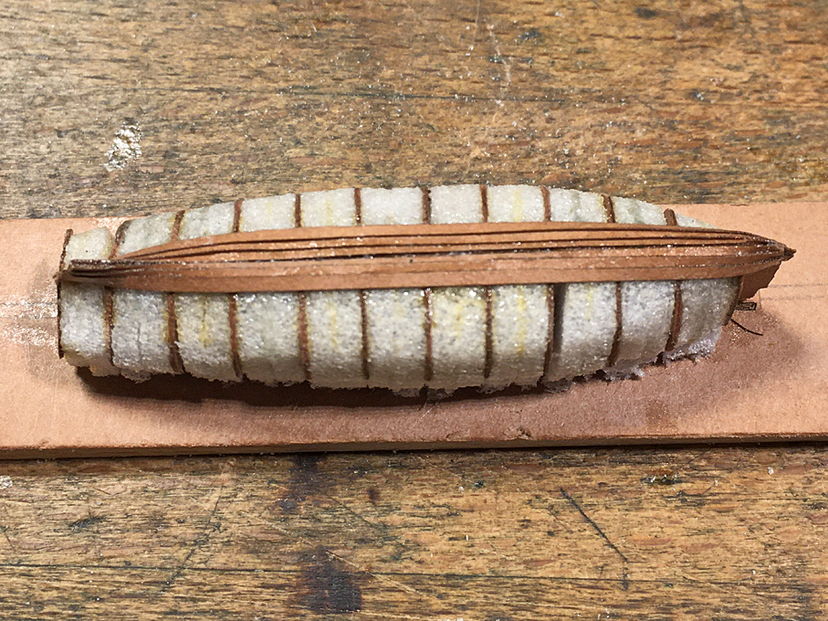
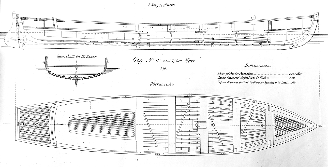
This has been buried deeply in my building-log for S.M.S. WESPE and not everyone is interested in 1870s warships. Thus, potentially interested people may have missed this description of building small-scale clinkered open boats. So, I decided to pull this part out, edit it for the purpose, and post it separately. Clinkered open boats in small scale (the examples below are in 1/160 or N-railway scale) can be a challenge. The processes described below are based on paper parts cut with a small and cheap 3W laser-cutter. If one has a stronger laser-cutter, the same method can be used with thicker cardboard or even styrene and may give even crisper results. There are even various laser-cut kits for such small boats in 1/72 on the market. Actually, the construction methods described below are adaptations of the well-known plank-on-bulkhead (POB) and plank-on-frame (POF) methods. Starting point, of course, are a set of suitable plans, line- and body-plan, plus ideally information on the actual construction, dimension of scantlings etc. Example of a drawing for a gig from the early 1880s. Two construction strategies are described one for boats covered with canvass, so that the interior structure is not visible and does not need to be modelled. The other example is for a plank-on-frame open boat model that shows all interior and construction details that one can possibly show at the chosen scale. Plank-on-Bulkhead (POB) construction of open boats closed with a cover Traditionally, one would carve a ‘plug’ for the boat from a piece of wood, that is based on the dimensions inside the planking(!). Such a plug can be re-used in case another copy of the boat would be needed. Otherwise, one can plank directly on the plug. For the method proposed here, each individual framing stations from the body plan was redrawn as a bulkhead to be cut out with the laser-cutter. Additional material is left on the top, so that all bulkhead scan be glued to a building board arriving at the right height. As backbone, a longitudinal profile of the boat, inside the planking, is drawn. All pieces were slotted as it is common practice in POB construction. The slots were twice as wide as the paper, as all pieces were cut in double to be soaked and varnished together back-to-back with a view to increase their stiffness. In addition, two pieces that represent the outboard profile of the stem-post, keel, and stern-post were cut, plus two copies of the transom. The bulkheads etc. were arranged on a drawing that controlled the laser-cutter. Template for laser-cutting the keel-pieces and the stem-keel-combinations for a cutter The material used is so-called Canson-paper, which is around 0.12 mm thick and an unglued, but heavily rolled paper. Its surface thus is quite smooth. This kind of paper turned out to be the most suitable for cutting with the low-powered (3W) laser-cutter. Laser-cut bulkheads and keel-pieces The pieces then are assembled as is tradition for POB-construction and mounted onto a piece of Canson-paper for extra stiffness. The whole assembly is then mounted on a small piece of wood to ease handling. The assembled parts for the POB-construction To increase the stiffness of the assembly (which in fact is already surprisingly robust), the spaces between the bulkheads are filled with a hard foam. I am using an acrylic resin foam, that is being produced by the manufacturers of Plexiglas, but any hard foam will do. The foam is sanded back to the profile of the bulkheads and then soaked in varnish. Imperfection can be corrected with automotive putty. This will give ample surface for the planking to attach to. Note that due to their thinness, the bulkheads do not need to be bevelled. Foam-filled framework with three strakes on The planks are laser-cut from the same paper. Tapering such planks by hand would be too much of a challenge and not quite feasible in paper, I think. However, my 2D-CAD program gives the length of the Bezier-curves used to draw the outline of the frames. So, one can simply take this length, divide it by the number of planks and add 50% for the clinker overlap in order to arrive at the plank width at each station. In reality that planks would overlap above and below only for about 25% of their width, but the extra width will not be seen on the completed model and gives extra leeway to accommodate small inaccuracies during construction. With this information somewhat too long planks were drawn with a few extras, as not all turn out well. A wider plank is provided for the garboard. In theory, the planks should not only be tapered, but also curved in the plane, but I do not have a software to develop a full planking diagram. However, when wetted with varnish, the paper, unlike wood, can be relatively easily bent and shaped across the wide side of the plank. Materials and tools for planking When laser-cutting the tapered planks, the curves are so shallow, that the ‘stepping’ due to the 0.1 mm resolution of the cutter becomes quite pronounced. For this reason, the planks were drawn with a straight line on one side and the tapering curve only on the other. The straight edge will become the visible lower edge of the plank, while the stepped, curved side will disappear under the plank above. When fitting the planks, the best way is to fix them in the middle first and then work towards the ends. As can be seen on some of the pictures, originally, I put the doubling of the stempost-keel piece in place before the planking in order form a rabbet against which the planks run. This turned out to be not very practical, as precise fitting is quite difficult with this material. Now I am drawing the backbone to the inside of the planking and add a false stempost-keel piece afterwards. This greatly facilitates the planking at the bow. Planking progresses from the middle to the ends All planks are cut flush to the interior backbone using a micro-scissors or cuticle scissors. When heavily soaked in varnish, the paper can be cautiously sanded. The soaking in fast-drying varnish has to be repeated after a few strokes with a diamond nail-file to prevent the paper from fraying. In clinker construction, at the bow, where it meets the stem-rabbet, the lower planks are thinned out by the width of the overlap and over a length of 1.5 to 2 plank widths or so. In this way the planks are flush at the rabbet. This is a feature, that at this scale is neigh impossible to reproduce, so one needs to cheat a bit again. Luckily, as long as the varnish is still wet, the paper can be squeezed and moulded. The thinning can also be simulated by squeezing the edge with flat pliers or splinter tweezers that have been ground flat at the end. While the varnish sets, the edges are squeezed tight using locking tweezers. The same thinning procedures is applied to where the planks touch the stern-post or the transom. Clamping the planks tight at the bows The planking is done mostly by eye, as it is difficult to mark out the planking run with sufficient precision on such a small workpiece. It is advisable to use an organic solvent-based varnish for the purpose. A drop of acetone softens the varnish and allows to make small corrections in the run of the planking. To be continued …
- 13 replies
-
- 17
-
-
-
-
Yep, hunting down materials can be a challenge, regardless where you are. And it seems to become more difficult with time, as many speciality shops disappear and other shops only stock what sells with a certain minimum quantity over the year 🤨
-
My newest Challenge
wefalck replied to James Flynn's topic in Building, Framing, Planking and plating a ships hull and deck
Would make a change to the usual kit-built cross-sections of HMS VICTORY 😁 -
My newest Challenge
wefalck replied to James Flynn's topic in Building, Framing, Planking and plating a ships hull and deck
If really wanted to reproduce a fully-framed model, you would need to make all those frames as shown above the keel in the blow-up below: All the vertical lines above the keel indicate frames. You would have to draw each of them, paste the drawing on suitable pieces of wood and then cut them out using a scroll-saw. Frames are also made of several pieces to ensure a good run of the wood-grain. So you would have to know from how many pieces the frames are made up of and reconstruct this pattern. This kind of construction usually goes by the term 'dockyard model' (though real dockyard models often used a simplified scheme of frames). If you search for this term here on the forum you will find several models constructed this way. In fact the Atlas du Genie Maritime gives all the construction details, but not necessarily for a particular ship. All this requires a lot of research, planning and drawing (i.e. real lofting, copying plans is not enough). Perhaps a worthwhile project, but one has to know that one will be spending probably a couple of years of spare time just for the preparations, before cutting any wood. I don't want to discourage you from such an ambitious project, but I have the feeling that you should build up some more basic knowledge of shipbuilding techniques pertaining to such large ships in the middle of the 19th century. Perhaps an idea would be to split the project in two, building a POB model of such a ship and another model of a considerably smaller ship that shows such interior arrangements ...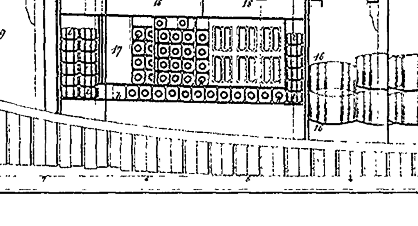
-
My newest Challenge
wefalck replied to James Flynn's topic in Building, Framing, Planking and plating a ships hull and deck
Another thing to consider: for a true POF contruction, you would have to loft dozen of intermediate frames, as they were spaced very closely on these ships, only a few inches apart ... a major investment in time and in material. -
My newest Challenge
wefalck replied to James Flynn's topic in Building, Framing, Planking and plating a ships hull and deck
Keep in mind that this is only the hull, the whole ship will be something like 50% longer, taking into consideration the bowsprit etc. However, I think you put a tall order onto your plate, something that will keep you busy for the next ten years ... -
My newest Challenge
wefalck replied to James Flynn's topic in Building, Framing, Planking and plating a ships hull and deck
There are data for the dimensions as well as a scale in metres for the small sail-plan. From this you can work out the scale for a hull of 4 ft. length. It seems that the hull was around 67 m long (= 220 ft., I didn't check where exactly this was measured), which means that at 4 ft. length we are talking of a scale of something like 1/55. -
On a German forum the colleagues try to coerce him to approach e.g. ANCRE to write up the building-log as compendium to (French) rigging practices in the early 19th century and their implementation in models 😁 Of course, this is entirely up to him and I know a couple of other exemplary modellers, who say that they rather spent their time at the workbench than at the computer-desk (and I can't blame them for that).
-
My newest Challenge
wefalck replied to James Flynn's topic in Building, Framing, Planking and plating a ships hull and deck
The drawings posted here and on the linked Web-site come from the 'Atlas du Genie Maritime' that was collated from the middle of the 19th century on until about the 1880s, so contains information and plans from different periods. There is also special volume on rigging details that is a fantastic source (see archjofo's building log for LA CREOLE). The exact contents of this Atlas varies depending on the different copies preserved. It was meant as a sample book and teaching resource for naval engineering students. Unfortunately, there never seems to have been a textbook with explanations for the numerous plates. Not sure what scale you want to build in. At the beginning you wrote the model would be 4" long, which is probably wrong. Otherwise it would be a veritable miniature. If you envisage such miniature, have a look at the building log in 1/700 scale here: http://www.shipmodels.info/mws_forum/viewtopic.php?f=59&t=382477. The two body-plans are, indeed, puzzling. As the lower one seems to show one more frame station I would venture the guess that it may refer to a possible lengthening of the ship, when in 1851 she was converted into an auxiliary steamer. However, Wikipedia on her is quite spartanic and I did not have time to dive deeper into her history. Lengething old warships to make space for machinery was a common procedure at the time. Concerning the language challenges: if one dives into a project from another country, one should be prepared to learn at least the basic terminology in that other language. Today it is easy to find on-line all sorts of specialised and period dictionaries due to the libraries digitising their holdings. Take modern bilingual on-line dictionaries with a pinch of salt - they do not always get it right ... Here are some useful dictionaries that also can be found on-line: PAASCH, H. (1885/1901): From Keel to Truck.- 206 + CIV p., New York/Antwerp. ... that's a classic for English, French, Dutch, and German, later also in addition for Spanisch and Italian. BONNEFOUX, P.-M.-J. DE (1834 and later editions): Dictionnaire abrége de marine. Contenant la traduction des termes les plus usuels, en anglais et en espagnol.- 338 p., Paris/Havre (J.A. Dezauche/C.-B. Matenas). BONNEFOUX, P.-M.-J. DE (1848?): Dictionnaire de Marine à Voiles et à Vapeur. Marine à Vapeur.- 771 p., X pl., Paris (Arthus Bertrand, Éditeur). -
Yep, phenolic resins are so much better, because harder, for many applications ... If you consider building a serving machine, you may also consider building yourself a rope-walk. Basically, you need the same kind of parts and materials, as for the serving machine. Ropes made from fly-tying threads or certain high-quality threads (e.g. Alterfil L 400, a German brand used now by various museums in Europe) will have a 'lay' and no fuzz.
- 2,699 replies
-
- 3
-
-
- heller
- soleil royal
- (and 9 more)
-
Perhaps it has become merged in my memory over the decades, but I seem to remember also to have seen one of those helmet divers at work then, perhaps to inspect that the piles were set correctly. A small barge with a handpump and crew, a diver on the ladder into the water, etc. could be a nice complement, but would be a real challenge in 1/120 scale 😁
-
To be honest, I don't remember, as it is many decades ago since I last saw one like this in action in a harbour. I was a small boy or teenaber at best then. Modern sheet-pile drivers in civil construction seem to work at higher frequencies and sound very metallic.


