


wefalck
-
Posts
6,354 -
Joined
-
Last visited
Content Type
Profiles
Forums
Gallery
Events
Posts posted by wefalck
-
-
Thanks ... the Bakelite-paper is semi-transparent, so that indeed parts underneath are shining through. After painting (eventually), nothing will be seen anymore.
-
Thanks, gentlemen, for your continuing encouragement and the many 'likes'
*****************************************************************************
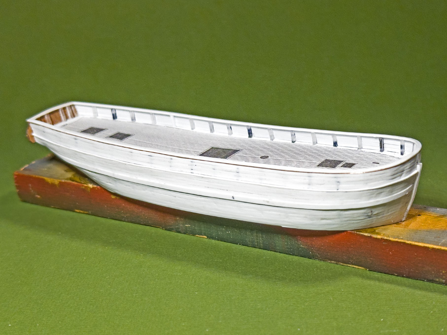
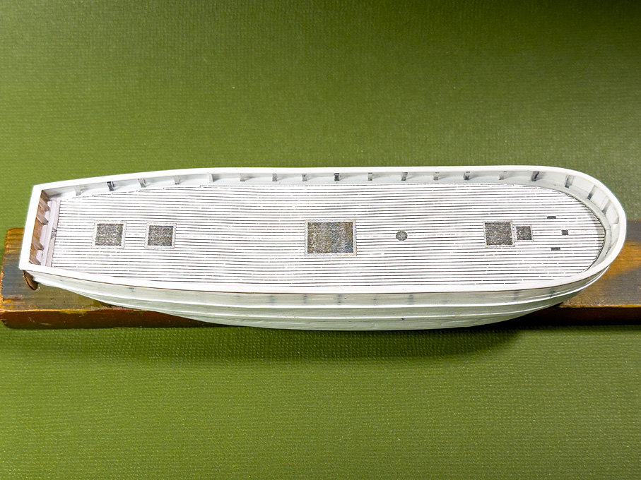
Fitting the deck
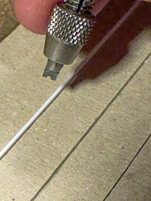
The deck is made from 0.4 mm thick Bakelite-paper. I find it easier to engrave the deck-seams consistently into this harder material with my tools, then into the softer styrene sheet. Perhaps I should get some day one of those hooked engraving tools the plastic modellers use (I have the suspicion these are the same tools as dentists use to scrape of ‘plaque’ – I have one of those and perhaps should have tried).
I first printed out the deck-drawing, cut out the shape and fitted it to the ship. Using the paper template, the shape was cut from the Bakelite with a small margin. This then was fitted very carefully in an evening’s session. Fitting started from the stern working forward, taking off material with a diamond nail-file while checking the fit after a couple of strokes.
A tight fit is important, as the whole idea is to paint the deck off-ship to avoid a complex masking exercise. Also, the painting process (as described in the build-log for SMS WESPE) would be difficult to exercise within the constraints of the bulwark.
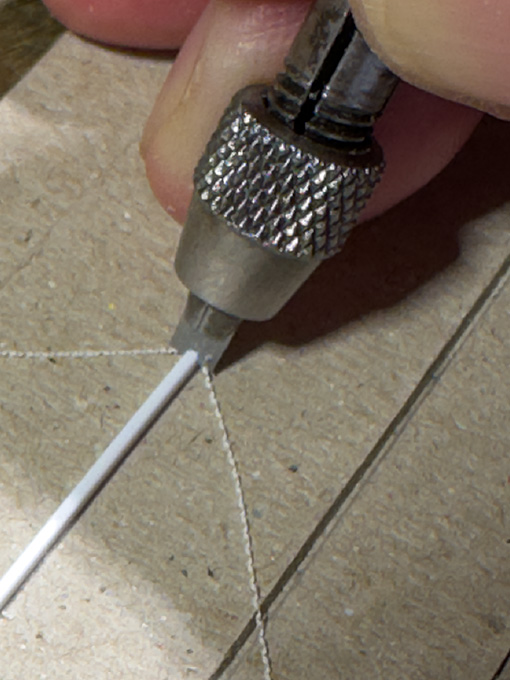
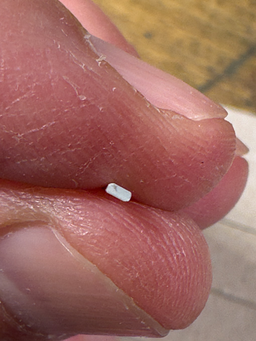
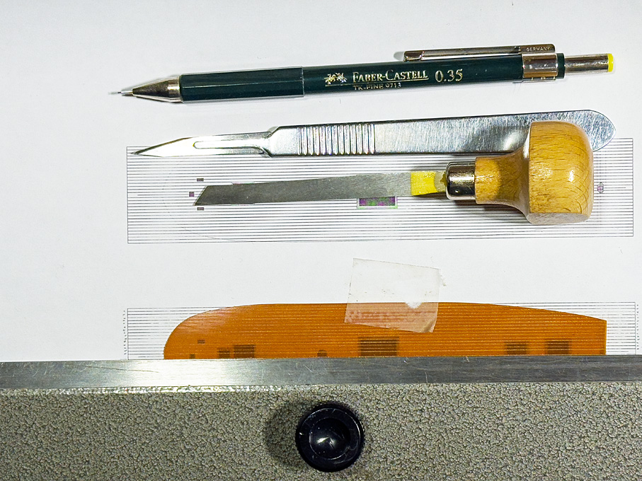 Tools used for engraving the deck seams
The fitted deck was taped to a printout of the deck with the planks marked as guidance for engraving. A heavy steel ruler ensured straight lines. First, the plank seam was marked with a scalpel to provide some ‘tooth’ for the graver. Then a narrow engraver’s graver was run twice along the ‘seam’ to clean out the shallow groove. Once the engraving was completed, the whole deck was thoroughly brushed with a rotary bristle-brush to remove burrs.
I ended up doing this three times, as in the first two attempts I lost count and cut a skewed seam. This is unrepairable, so I had to start all over again. However, the first fitted deck provided a good template, speeding up the fitting process: after scoring the material with a scalpel around the edges of the template, one can break the new deck out of the bakelite sheet. Only comparatively little fitting was required then.
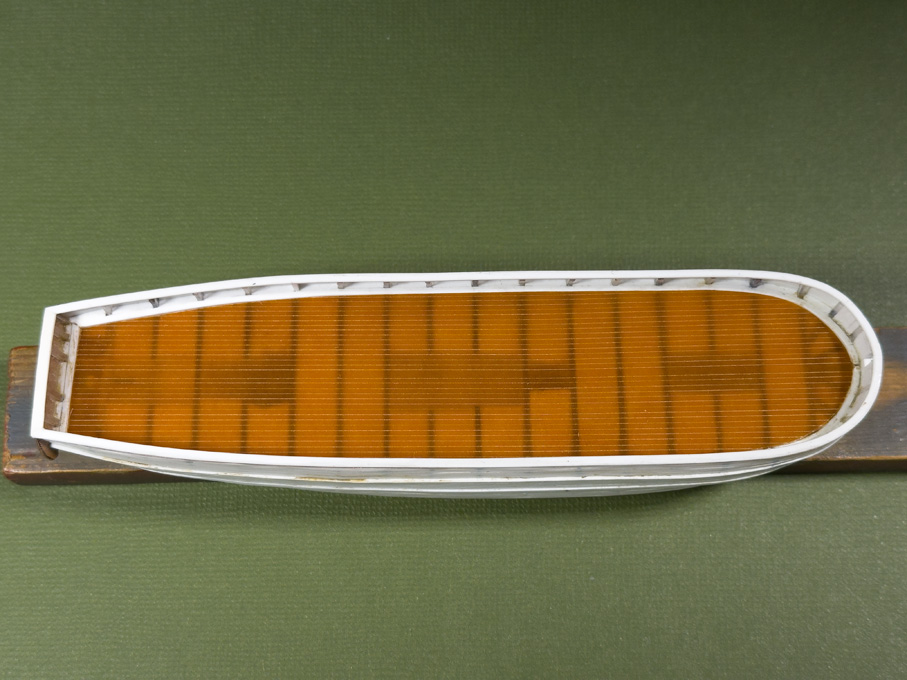
In fact, scoring the bakelite-paper with a scalpel twice and then breaking along the line is a quick and clean way of getting straight cuts that just require a bit of sanding with a diamond file.
The next step would be to cut out the openings for the companionways and hatches. However, these have to be tight fits to them and it will be easier to first build those and then file out the openings – back to the drawing-board for some time.
To be continued …
-
Oops, missed the continuation of this new project ... have been travelling too much the last few weeks.
When I used very thin copper-sheet to simulate hull plating and pouncing the rivets, I found that rubbing them down from the front with a cork (Champagne corks work best, because of their round lower edges and sort of integrated handle) reduces the distortion of the sheet and gives a more realistic look. I have not tried the same with styrene sheet. Not sure that it would work, because it is less malleable than copper, but it may be worth a try.
Another material that I have used is this self-adhesive aluminium tape that is used to cover up the seams in dry-walling. However, I have used it only only represent rivetted reenforcement strips, not larger surfaces, as I am a bit weary of self-adhesive materials - the adhesive film might dry out and become brittle with time.
- Canute, Keith Black, Valeriy V and 1 other
-
 4
4
-
Perhaps you could use cardboard-templates to work out the geometry?
-
-
You are absolutely right, the 'caboose' as a temporary deck fixture was very common between the early decades of the 19th and about the last quarter of it. They were usually lashed down onto the deck with one or more iron (or wooden) bars over their into which iron rods were hooked or screwed. When they were hooked, the rod had ring at the lower end and a lanyard between this ring and an eye-bolt was used to lash it down. The other option was to hook the rod into the eye-bolt on deck and tighten the threaded rod down with a nut at the upper end.
Below is an example from a German museum model:
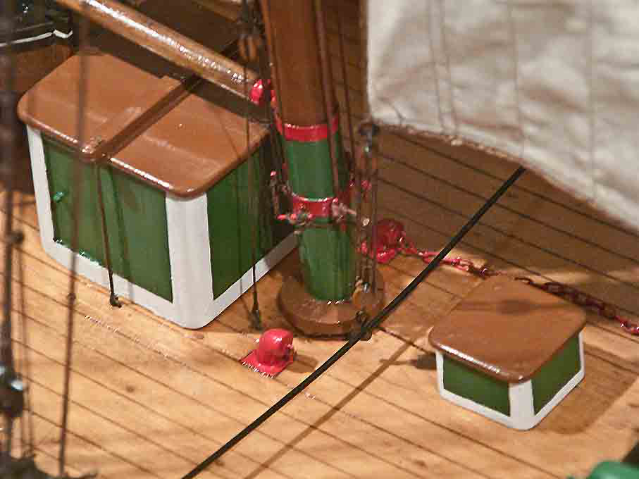
One also see this kind of arrangements on early photographs of sailing ships from both sides of the Big Pond.
Caps and companionways as such where not necessarily permantly fixed to their coamings, but may have been removable to be stowed away under deck, e.g. when really severe weather was expected. In this case the opening would be closed with a simple lid that was less prone to be washed away and thus give water access to the interior of the ship.
- Kenchington and Baker
-
2
-
BTW, decks should not be 'varnished', decks were always left bare wood on the prototype. If you use varnish or sanding filler, you should rub down the deck with very fine steelwool, so that no visible varnish layer is left on the surface.
-
Another option would be sheet brass. Strong structures can be build from very thin sheet bent and soldered together. When one sticks it to thin plywood or MDF, it can be sawn easily and precisely without distortions.
Personally, I think (nearer to) scale thickness is greatly enhancing the look when structures are hollow and with a lot of see-through windows in them.
-
Well, people tend to confuse 'scale' with 'size'. It doesn't really matter at what scale you are working, the size of features, both small and large can matter ...
Obviously, the thicker the material, the more difficult it is to cut it with a scalpel. On the other hand, with thin material, it is more difficult to correct cuts by filing or sanding. If you are working at 1/200 scale a sheet of 0.02" (=0.5 mm) thickness would translate to walls o 4" (= 100 mm) thickness, which would be quite formidable, even if in wood. So chosing thinner material will make your life easier from a cutting point of view.
Perhaps you should reconsider your construction technique. I assume that you use the styrene sheet as structural material, i.e. you are building a hollow structure? Unless you want to show some interior details, it may be a good idea to build a structure from wood or thicker styrene and clad this with 0.01" styrene sheet into which you can cut the window etc. openings.
For me the reason to use styrene sheet would be mainly that it looks more like steel when painted, than most efforts of filling and sanding wood.
When laying out the styrene for cutting, I would use a sharp scriber to mark the window openings. The scribed lines form a guide for the scalpel cut, even if you use a ruler. Make an incision in the corners first from both sides in order achieve crisp corners.
- JKC27, tkay11 and Keith Black
-
3
-
-
New York may be the same latitude as Naples, but they don't have there the Alps to keep the winds from the North Pole away 🥶 ... reminds me of a Christmas there many decades ago, when we had -30°C due to the chill-factor.
- Keith Black, FriedClams and Canute
-
1
-
 2
2
-
There are different formulations of acrylic paints. Some only use water as 'medium', while others may have a mixture of water and some kind of alcohol. Some may also contain some sort of detergent to reduce the surface tension of water (aka as 'flow improvers'). So, the 'thinner' should be compatible with the 'medium' used in the paint formulation to prevent coagulation.
I doubt that with pure water one would be able to clean out acrylics from a brush. You need something that encapsulates the binder molecules (the acrylic resin) that otherwise have the tendency to stick to the hair of the brush (which indeed is their purpose). This is a fairly complex physico-chemical process and normally some sort of detergent ('soap') is used.
I was given a pot of 'brush soap' by my wife, but historically have used washing powder for wool. The latter is a mild detergent designed to not damage the natural animal hair (i.e. the wool).
-
Agreed. I have the feeling the hitches were suggested by the model instructions because it seems easier than making seizings ...
-
This is presumably a way to stop the lanyard and to stow excess length of it - a kind of seizing done with the lanyard itself. I would feel more comfortable with a couple of real seizing though. Perhaps this was done on real ships.
-
I wish you a steady hand, and strong arm- and back-muscles to see you through this part of the project 👍🏻
- archjofo, Keith Black and cotrecerf
-
3
-
I have used synthetic brushes from the DaVinci range with acrylics for decades and always was quite happy with them. Not sure what brands you would get in Canada.
I gather the scaly surface structure of natural hair helps to keep more paint in the brush than the smooth synthetic fibres. This can be useful, when painting long lines with round brushes and in similar situations.
I actually also bought flat synthetic brushes from cheap Chinese sources and they are very soft and elastic, good for painting larger areas.
In general, I do not buy round pointed brushes on-line, but prefer to test the point in the shop myself (with a bit of spit between the fingers ...). On the other hand, if you buy on-line from a reputed supplier and you can show that a branded product does not form a proper point, they will replace it (at least in my experience).
The reason for buying on-line in the latter case was, that neither of the two or three art supply-shops here in Paris had undamaged brushes in their racks. People do not pay attention, when putting the protective sleeves back and break or bend hairs 😡
BTW it is not the water that damages natural hair brushes, but the solvents and detergents used to clean them. After all, the highest quality brushes for watercolour painting are the Kolinsky sable brushes already mentioned by @druxey.
-
I like this 'banged together'-look, gives you a real impression of a hard working boat. We tend to make our models often to yacht-like, probably to show off our modelling skills.
-
This is a recommendation by manufacturers (e.g. DaVinci) and art materials supply-houses. No explanation given, but I assume that the detergents and solvents used to clean out acrylic paints may damage the natural structure of the hair - raising the scale-like structures of the hairs, making them rough and less pliable. Ask your wife about using too aggressive shampoo ...
-
Thanks for the 'likes' !
***********************
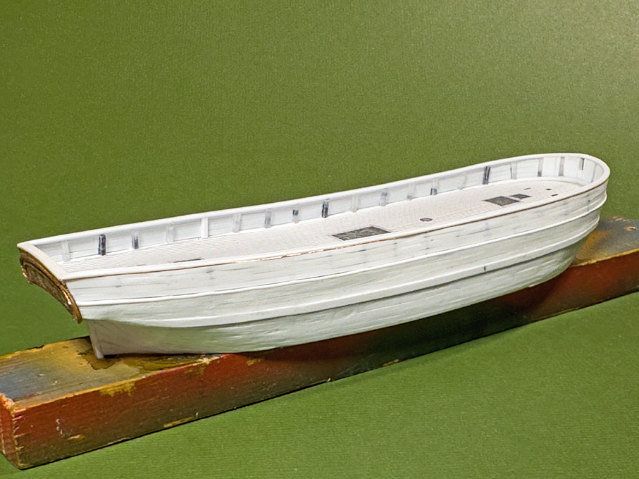
Fitting the rails
The rails are 0.75 mm x 1.50 mm styrene strips on top of the bulwark and a 0.75 mm x 2.00 mm strip over the stern. The edges of the strips are rounded.
To this end I cut a scraper from a piece of razor-blade which is held in a short pin-vice. The strip is held in a simple jig made from cardboard. Strips of cardboard were cut with clean and vertical edges and glued to a cardboard-base so that styrene strips of 0.25 mm, 0.50, and 0.75 mm thickness can be wedged into the resulting notch, holding it straight and vertical.
In this way a clean and uniform profile of the styrene strip can be achieved quickly.
The styrene strips then were pre-bend, holding them lightly in round-nosed pliers and by ‘massaging’ them around my thumb to make them conform to the sheer-line as closely as possible. They then were glued onto the stanchions and the top bulwark strake using styrene-cement.
As can be seen from the cross-section shown in the previous post, the profile of the rail may be even more sophisticated with some cornice planed in. I simulated this my lacquering a 0.1 mm copper wire into the outboard corner under the rail.
The next step will be puttying up any small gaps that have developed during the planking process.
As one can see on the pictures, I also started to work on the deck by making a paper template for it.
To be continued …
-
Very intricate and detailed structure. Love these kinds of details 👍🏻
- Canute, Keith Black and FriedClams
-
3
-
-
In fact, the heat is the key aspect. Water is mainly used to prevent the wood from burning, when doing the bending over an open fire (as was done in the old days).
The steam in steam-chests serves mainly as a carrier for the heat - the heat-capacity of steam is much higher than that of air.
As we now have heat-guns readily available, this is probably the best option.
-
I don't want to question the professionalism of Jack's son, but I would have doubts using a wire brush on an artist's hair-brush. The hairs are just too delicate.
It is quite normal that paint wicks into the hair inside the ferrule, even if you don't dip the brush down to the ferrule into the paint. As long as the solidified part does not extend beyond, this has no practical consequences.
The best advice for getting the paint out of the ferrule was already given above: the appropriate solvent.
It is also quite normal that a wet flat brush looks like in the picture above. Once clean and dry, the hairs will separate again.
Personally, I find brush-painting acrylics over larger surfaces quite difficult. Perhaps a 'retarder' can keep the paint longer workable, resulting in better surfaces. I normally use an air-brush.
-
... until they become pliable 😁 ... It depends inter alia on their tickness.


Pomeranian Rahschlup 1846 by wefalck – 1/160 scale – single-masted Baltic trading vessel
in - Build logs for subjects built 1801 - 1850
Posted
Thanks for your comments @mcb!
It is actually the 'old' duroplastic material invented by Baekelundt. It is essentially one or more layers of paper soaked in phenolic resin and cured between steel plates to ensure uniform thickness and a mirror-like surface.
It is still used for electrical insulation and certain types of PCBs, a class called FR-2: https://en.wikipedia.org/wiki/FR-2.
It is available from thicknesses from 0.1 mm up to 6 mm or even in blocks and rods (usually with cotton-fabric, rather than paper). I got a life-time supply about 30 years ago from a specialised dealer in Berlin, who sold it by the meter.
You can find suppliers on the Internet (including on ebay). Most of the material seems to be produced in India and China these days.
It glues very well with CA - some 25 years ago a made little clinkered boat with bakelite-paper planks glued with CA and it still looks pristine. For larger flat pieces I also used zapon-varnish, which adheres well.
The edges of the bakelite-paper are quite brittle, so care and sharp tools are needed, when cutting it. It sands well with fine diamond nail-files.