


wefalck
-
Posts
6,354 -
Joined
-
Last visited
Content Type
Profiles
Forums
Gallery
Events
Posts posted by wefalck
-
-
-
Never had to build one, but in general, in situ-construction ensures that the part actually fits. Otherwise, you would need to have a sort of jig that exactly reproduces the attachment points. Perhaps a hybrid strategy, building the elements that attach to the ship in situ, taking them off and completing the structure off-ship might help.
-
I think on a 'real' ship they would be called 'knightheads', but these are heavy timbers that bolt onto the deadwood.
-
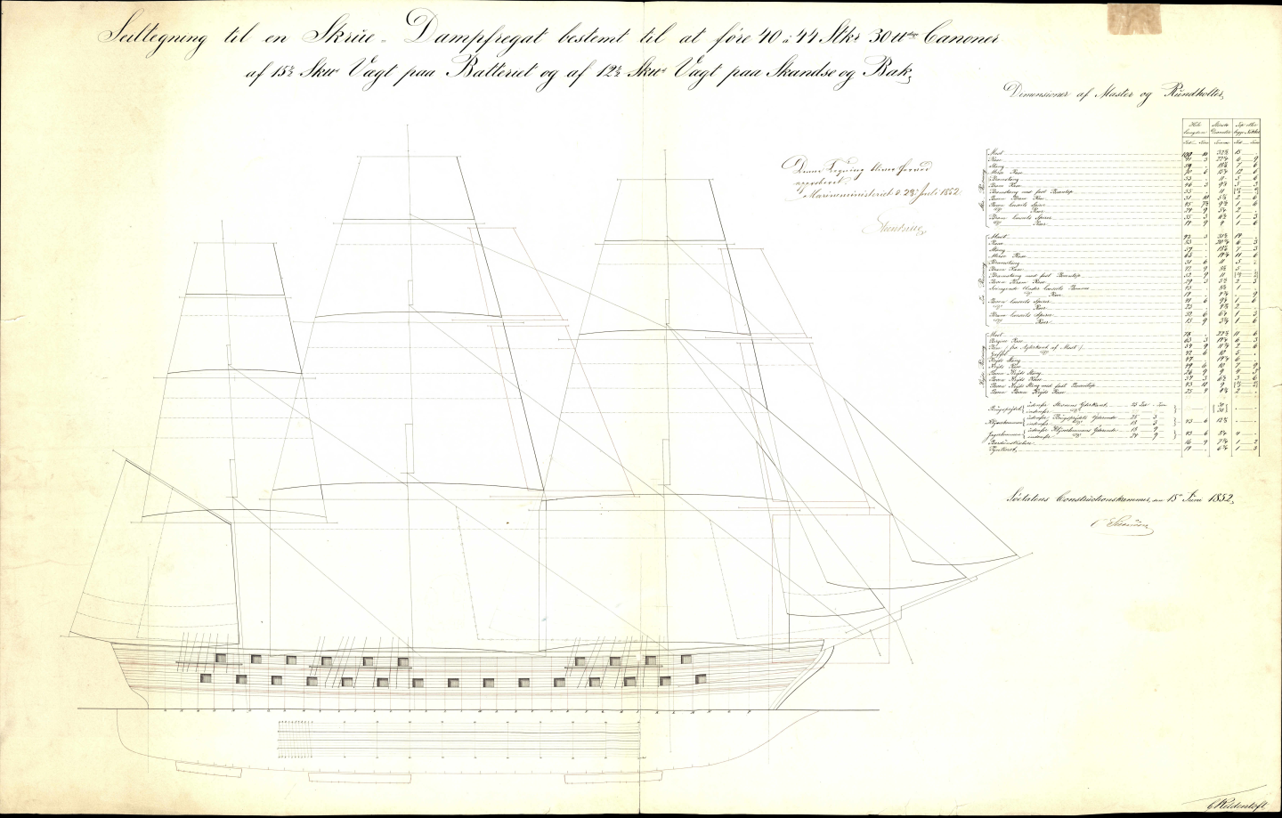
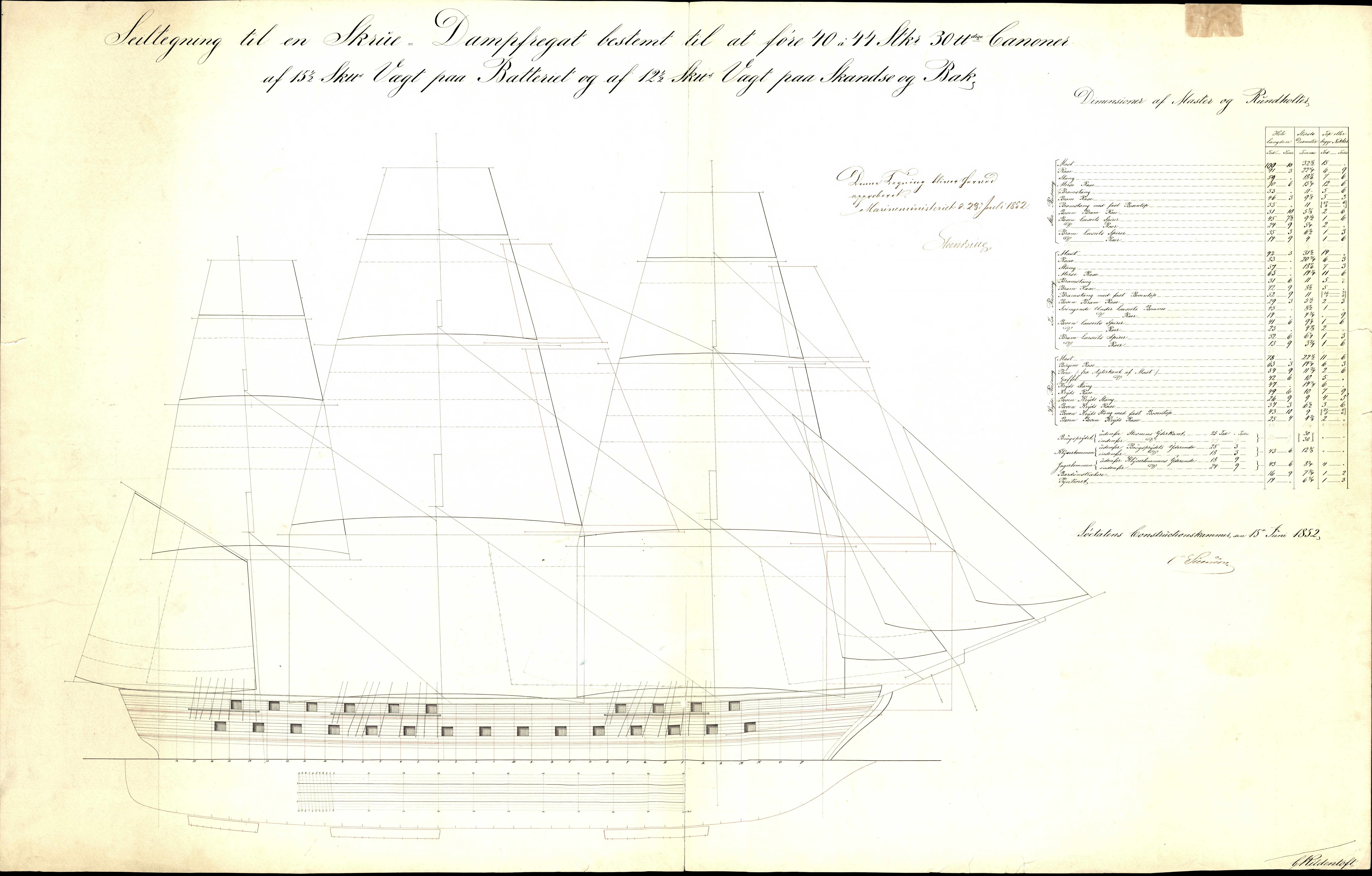
For drawings on Danish naval artillery 1850ff you may want to browse the archive for number G2092 and above:
https://arkivalieronline.rigsarkivet.dk/da/billedviser?epid=17149179#190263,31920089
As I said earlier, rigging plans and details can be found under numbers G1872 and above: https://arkivalieronline.rigsarkivet.dk/da/billedviser?epid=17149179#190444,31922330
-
With these 'non-standardised' designs, one can always take a bit of artistic license. The builders themselves probably would have adapted to circumstances.
I wonder, why they used this stepped design of the stanchions? Did bolts go through the 'ears' into the covering board?
It is common design for rails to either extend the frames above the covering board or to bolt some thinner material to the frames that then extends upwards. However, these low rails probably only served to keep equipment or loads from rolling over board, so they don't need to be terribly sturdy.
-
Didn't I send you at some stage a list of all the drawings that pertain to JYLLAND from the archives of the Danish Navy Shipyard?
Basically, archival Nos. G1859 to G1896 pertain to her, including a rigging plan (G1872 and G1873). There are additional mast details at G4882 to G4900.
The mast actually look surprisingly vertical.
- kruginmi and Keith Black
-
 2
2
-
Slow Progress (as usual)
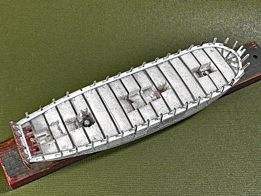
The run of the planking and their layout will be determined by three structural members, namely the rail on the bulwark as upper edge, the covering board, which marks the lower edge of the bulwark and the upper edge of which is marked in the original drawings, and the wales, the upper edge of which are also marked in the original drawings.
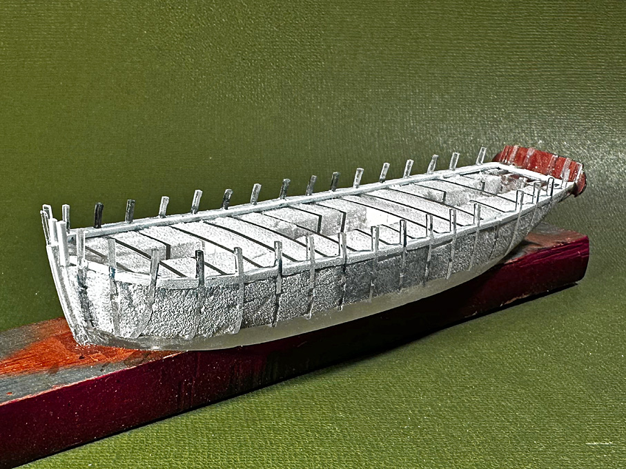
In order to physically define the top edge of the covering board, the waterways have to be installed first. The consist of a 1 mm x 1 mm styrene strip running along the inside of the bulwark stanchions. This is thicker than the actual water ways would be, but the thickness includes that of the covering board inside the bulwark stanchions. The space between the stanchions was filled with small pieces of 1 mm x 1.5 mm styrene strip. This is a tad wider than needed, but allows me to sand them down to the actual profile outside of the stanchions. While in theory the stanchions are spaced equidistant, the filling pieces still required a bit of sanding to fit them snuggly.
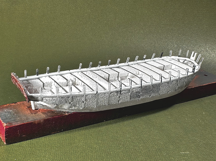
There are actually many different designs for the waterway/covering board arrangement and not any particular construction method is being followed here. The idea is to give the right visual impression after painting, not to follow prototype construction method. In fact, it would have been rather difficult to cut out the notches for the stanchions from the styrene strip representing the covering board at these dimensions, as would have been the prototype method.
The arrangement will be completed by a 0.5 mm x 0.75 styrene strip that will be shaped to a half-round profile using a scraper fashioned from a piece of razor-blade and that will be cemented along the upper edge of the covering board.
To be continued
- Bedford, vossiewulf, Rudolf and 9 others
-
12
-
Yep, jigs make life easier and more precise 👍🏻
- FriedClams, Keith Black and Canute
-
3
-
Again 'fonds dur' is an application, that can be achieved with a variety of materials, such as shellac plus pumice (the basis of classical 'French Polish'), nitrocellulose plus pumice, acrylics plus something as filler etc.
-
These hot glues work for almost everything, but 'technically' they are not quite correct solutions. There is also the risk that when the plasticisers diffuse out, the bond becomes brittle and the glued parts fall apart ...
- Canute and thibaultron
-
2
-
The problem is that people confuse 'materials' with 'applications'. A lot of materials can be used for the same application and a lot materials can be used for different applications.
Shellac can be used as a cement, as a varnish, as a binder in paints (with pigments added), as sanding sealer (with pumice added), for seals, etc. etc.
I fully agree and have repeatedly said so in this forum, that mixing varnish- and paint-systems can lead to trouble unless you really know what you are doing.
-
Not sure, why people differetiate between shellac and 'varnish'. Shellac can be used as a varnish among other applications.
A varnish consists of some material that form a continuous coating, e.g. a resin or a oxidising oil, and a solvent that allows to apply this material and vaporises after application.
- vossiewulf, paul ron, RossR and 1 other
-
4
-
You could dissolve some of the acetate in acetone and use this as liquid cement. If the wood surface is still raw, you can use this solution also as sealer, to which then the acetate should adhere well.
- Canute and thibaultron
-
2
-
Are the engine service-doors already glued in? Otherwise you could leave them open to give a glimpse of the engines ...
- Canute, JacquesCousteau, Cathead and 4 others
-
7
-
Do you have Underhill's 'Masting and Rigging ...'? That should give you the detailed information for that period.
- Ian_Grant, Tony Hunt, Glen McGuire and 1 other
-
4
-
Sometimes repairs can make things worse ... are these digs and dents very obvious? If they blend into the general rougher look of those boats, I would leave them like they are, particularly, when the areas are to be painted anyway.
- Bryan Woods, Paul Le Wol, Keith Black and 2 others
-
4
-
 1
1
-
5 hours ago, Mark Pearse said:
Hi Vaddoc,
If it is a print that you are talking about, one possible reason for a small error is that some printers slightly shrink to fit the page, without telling you. If you drafted in CAD to a certain size virtual page (eg A3), then when you print, you print to A3 paper size, but the virtual A3 is slightly reduced by the edge margin of the paper that the printer can't print on. The solution is to find the option in the print dialogue window that allows you to set the printing to 100% scale.
I have had a similar experience (albeit at a much smaller scale and physical size). I found that the prints came out 0.5% too small in x and y. So I am now creating a duplicate layer in my 2D-CAD in which I place the items to be printed and scale them at 100.5%. You can always check the measure of the printout with the theoretical value in the CAD-drawing.
- FriedClams and Keith Black
-
2
-
Distant diagnoses are always tricky, but I would cut the deck-sheet to size, rub it downs somewhat with sandpaper, apply sanding sealer, rub it down again with fine sandpaper, another coat of sanding sealer, and finally rubbing with fine (0000) steel-wool. That should give you thin sheets of decking with a satin finish, ready to be glued into place.
-
According to the 2nd Law of Thermodynamics everything will crumble away sooner or later - unless one spends energy and material on its upkeep (restoration is quasi periodic upkeep).
I agree that it is not so easy to find good quality paper and cardboard. I quite like Bristol-board, which is a wood- and acid-free cardboard that has a smooth calandered (rolled) surface. It is even more difficult to find very thin calandered paper - I have been hoarding supplies that came to me from deceased relatives and that may well be 60, 80, or even 100 years old.
Ab, as restorer is certainly painfully aware of this, that certain materials are simply not made anymore, because they are not used anymore or would be used only in such small quantities that it doesn't pay to make them. For instance I have been hunting down all over Europe a type of extremly fine and firm two-ply thread that was once used to darn ladies' stockings. Nobody bothers with mending stockings anymore, at least not with the old-time nearly invisble darning techniques, so that these yarns have disappeared from the market.
Sorry, I am digressing ...
- shipman, GrandpaPhil, Doreltomin and 1 other
-
4
-
But there are wood- and acid-free carboards these days. OK they are more expensive. I remember at least one art shop in Alkmaar that sells them.
- Ab Hoving and Doreltomin
-
2
-
In principle yes and it was also my first thought, but I think the images above show actually relatively wide double-banked boats.
-
Indeed these parts look excellent and one would have quite a time to make them from styrene strips etc. so consistently and with the 'drafts' as on real cast parts. 3D-printing is the future of high-end scratch-building ...
I am a bit confused that you mentioned PLA as material together with SLA as printing technique. I thought that PLA is only used together with filament printers (FDM), but the parts look actually as done with a SLA printer.
- Ras Ambrioso, Jack12477, Glen McGuire and 2 others
-
4
-
1
-
Perhaps the banks without tholes are meant to seat marines during landing operations?
-
Sure, a model with shiny brass guns can show off good handcraft. I you want to stay them like that, you can brush them in zapon-varnish as used to protect silver-ware.
Otherwise, it is a question, whether the prototype was bronze, cast-iron or (later) steel. At all times guns were not left to themselves, but various methods of corrosion protection where applied.
The archetypal black colour, of course, comes from black paint as applied mostly to cast-iron guns.
Bronze guns were given what the artists would call a patina. There is a wide range of recipes for that, resulting in a slightly metallic brown or dark green. The bright green as seen on coppered roofs is a sign of corrosion and would not be seen on guns in service.
Cast-iron and steel-guns in some navies were also rubbed down with vinegar, which resulted in the formation of 'rust', actually in this case ferric acetate mixed with ferric oxyhdrate. This rust layer then was solidified by rubbing it with lineseed oil. De facto one created a dark reddish brown paint (like caput mortuum) in situ, protecting the gun from further corrosion.
In later years, when breech-loading steel guns were introduced, the vinegar method could have damaged the mechanism, so brown paint of a similar appearance was used instead.
Hanks for attaching staysails to stays
in Masting, rigging and sails
Posted
"Some people call the rope coils created when belaying ropes to belaying pins "hanks" but this is a misuse of the term."
I am not a native English speaker (though I consider myself bilingual ...), but for me a hank of yarn/rope was yarn or rope coiled up. The use of the term 'hank' for the kind of hooks used to attach staysails to stays seems to be in line with the etymology of the word: https://en.wiktionary.org/wiki/hank.
In German we call these thingies 'Stagreiter' i.e. 'stay-rider' ...