EdT
-
Posts
2,214 -
Joined
-
Last visited
Content Type
Profiles
Forums
Gallery
Events
Everything posted by EdT
-
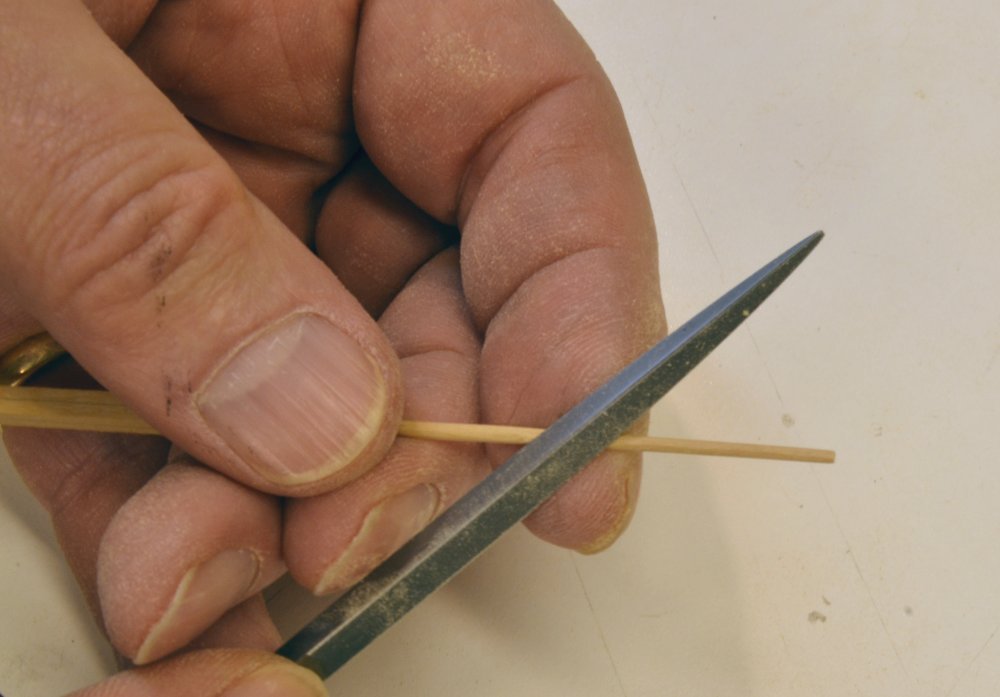
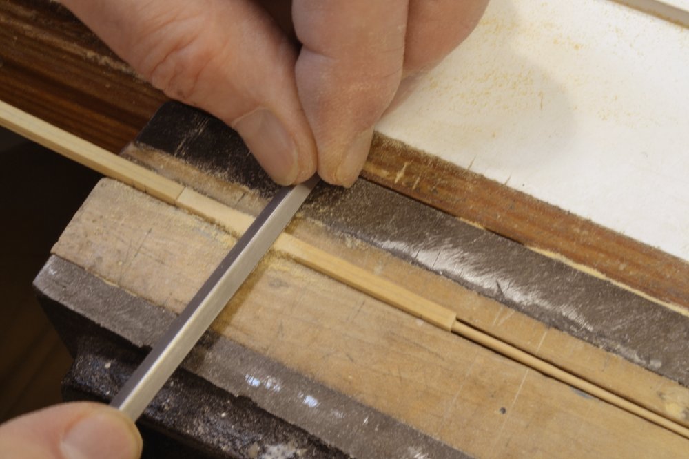
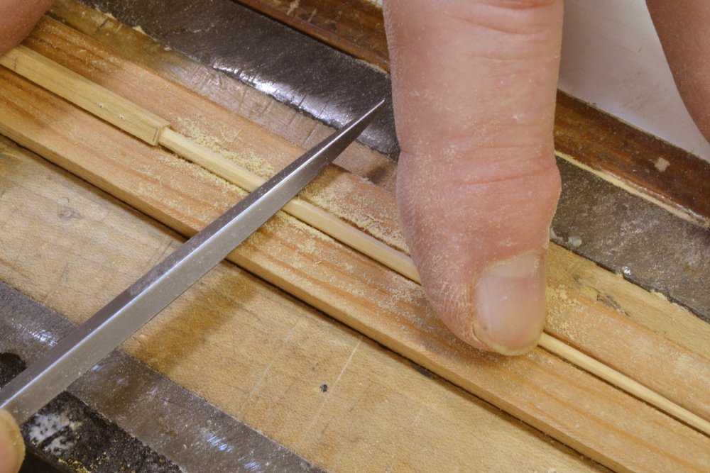
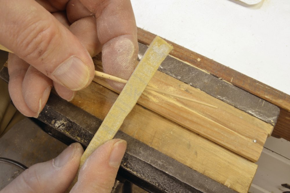
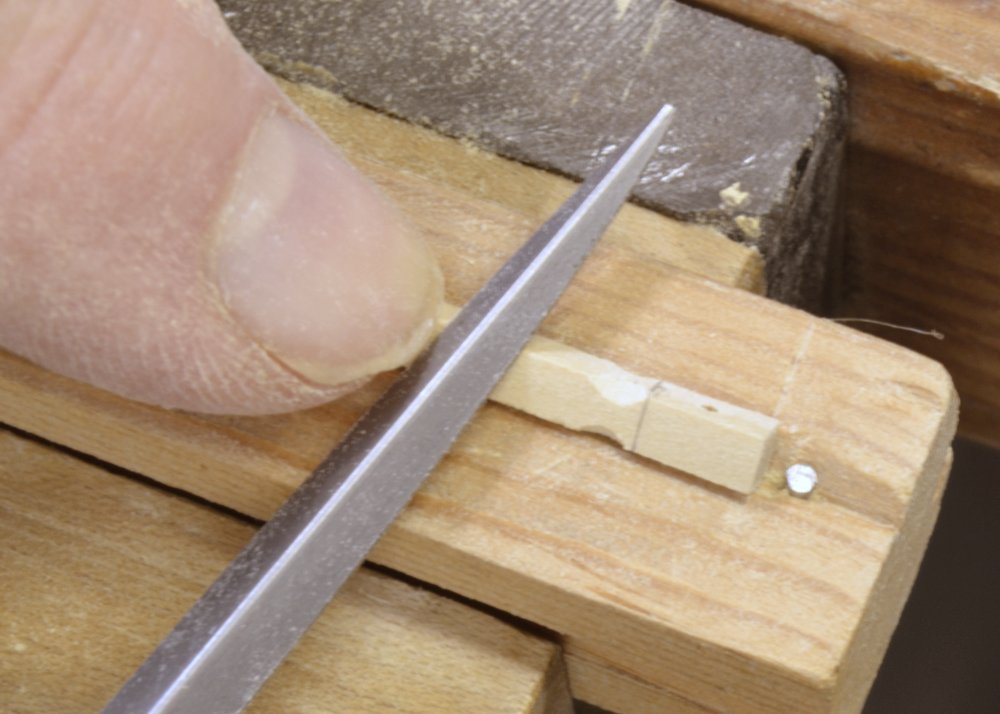
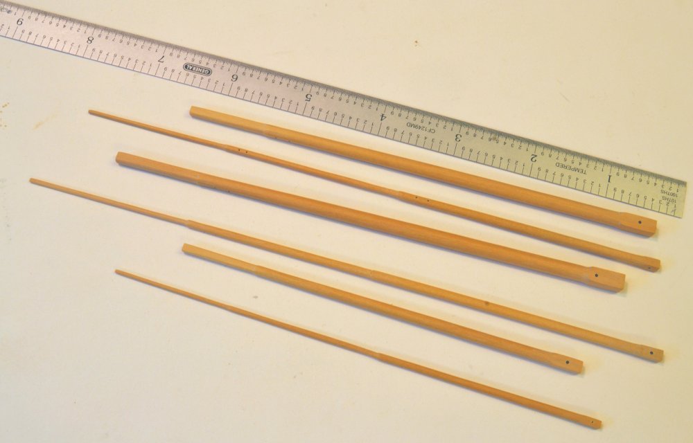
Young America - extreme clipper 1853 Part 286 – Upper Masts I decided to make the six upper masts at one go. This will allow me to use one basic set up of the milling machine to bore the holes in each of the six remaining caps and for the yard parral yokes. It will also permit the actual finished mast diameters to be used to set the bore diameters. This should ensure a tight but smooth fit on the caps. The six masts include the three topgallant masts and the three single-stick royal/skysail/pole masts. The topgallants were made by the process described in the last post. In making the combined masts I started with the upper pole sections first and worked down. The first picture shows one of the very slender poles being rounded. After rounding the pole one of the skysails sections has been stepped is being tapered in the next picture. Each section was converted to an octagon as shown in the next picture. On these small pieces the octagons are too small to be marked as was done on the lower masts, sothey were formed by eye with frequent measurement checks. The next picture shows one of the small poles being sanded to its final size. The pole and royal sections on one of these are shown completed in the next picture. In the next picture the fillet at the foot of a royal section has been filed and work on the octagon is in progress. Finally, the six completed masts. Trucks need to be added to the tops of the poles, the fid openings need to be squared, and all the sheave openings need to be formed. The next step will be to make the caps and parral yokes based on these finished pieces. Ed
- 3,618 replies
-
- 37
-

-
- young america
- clipper
- (and 1 more)
-
HMCSS Victoria 1855 by BANYAN - 1:72
EdT replied to BANYAN's topic in - Build logs for subjects built 1851 - 1900
Lovely metalwork, Pat. I assume you milled the circular track? Ed- 1,013 replies
-
- 5
-
-
- gun dispatch vessel
- victoria
- (and 2 more)
-
I was thinking the same thing, Sailor, but we have to remember that this ship was about as long as a football field and almost as tall. Ed
- 3,618 replies
-
- 5
-
-
- young america
- clipper
- (and 1 more)
-
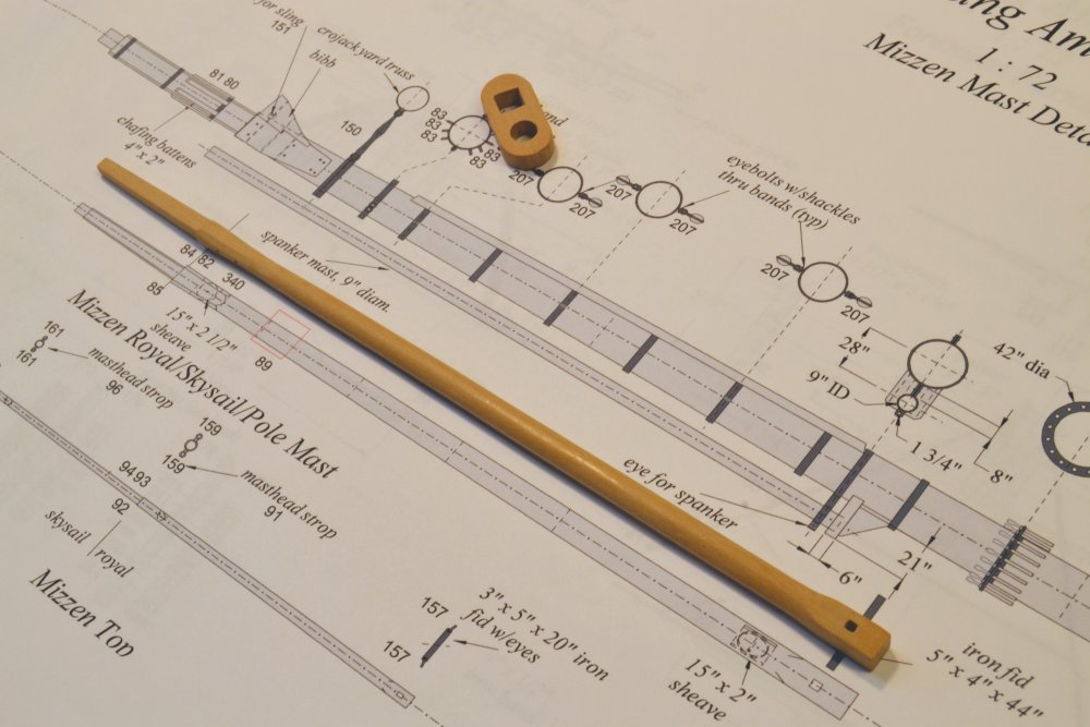
Sailor, I believe the fid hole in the last photo is 5" x 4" to fit the rectangular iron fid of that section. You will see those dimensions in the lower corner of the drawing in the picture. Fid sizes on the model range from 6"x 4" down to 3"x 2". Ed
- 3,618 replies
-
- 2
-
-
- young america
- clipper
- (and 1 more)
-
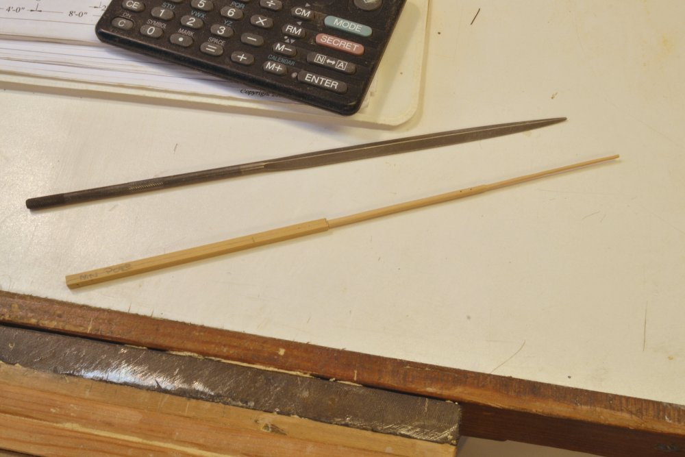
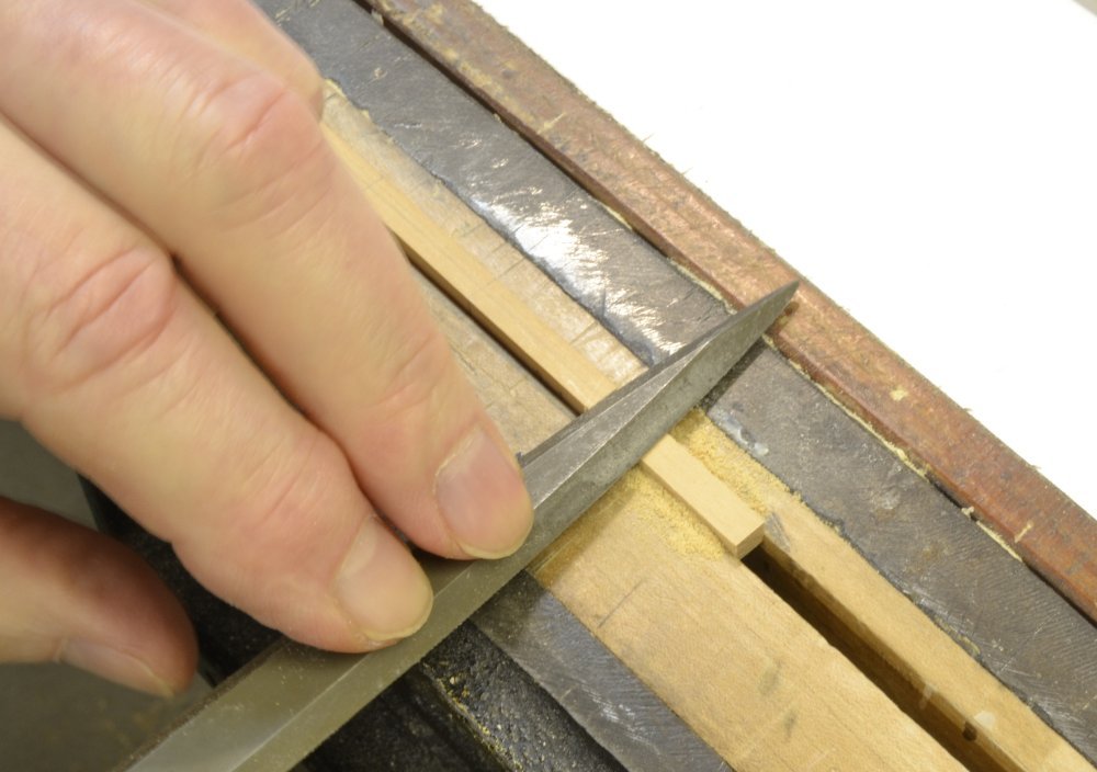
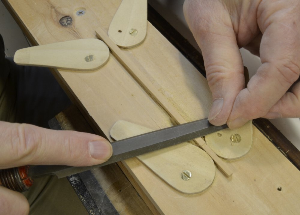
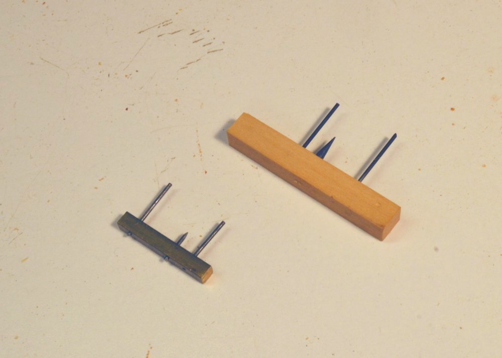
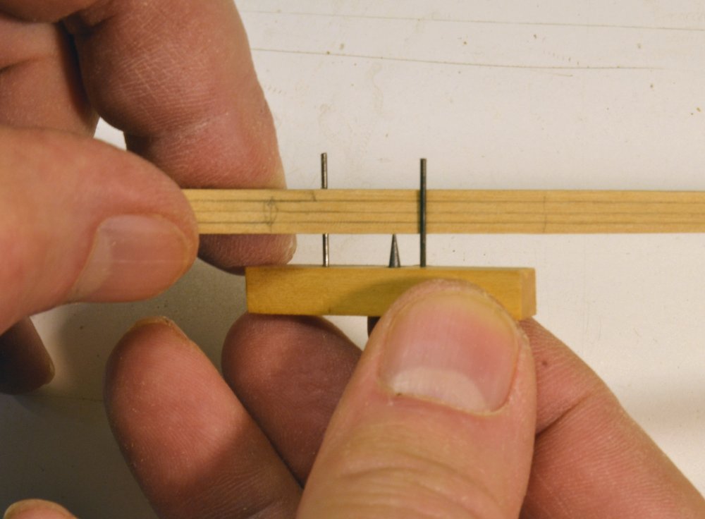
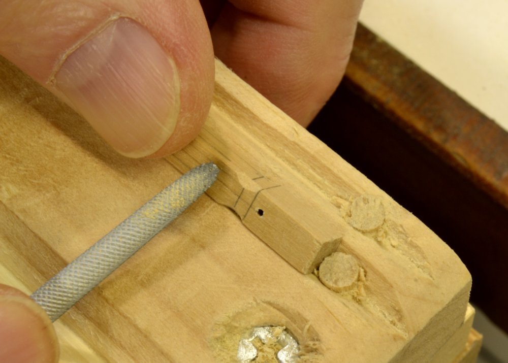
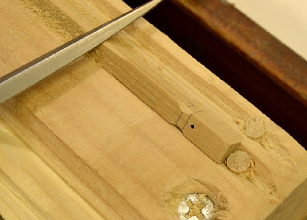
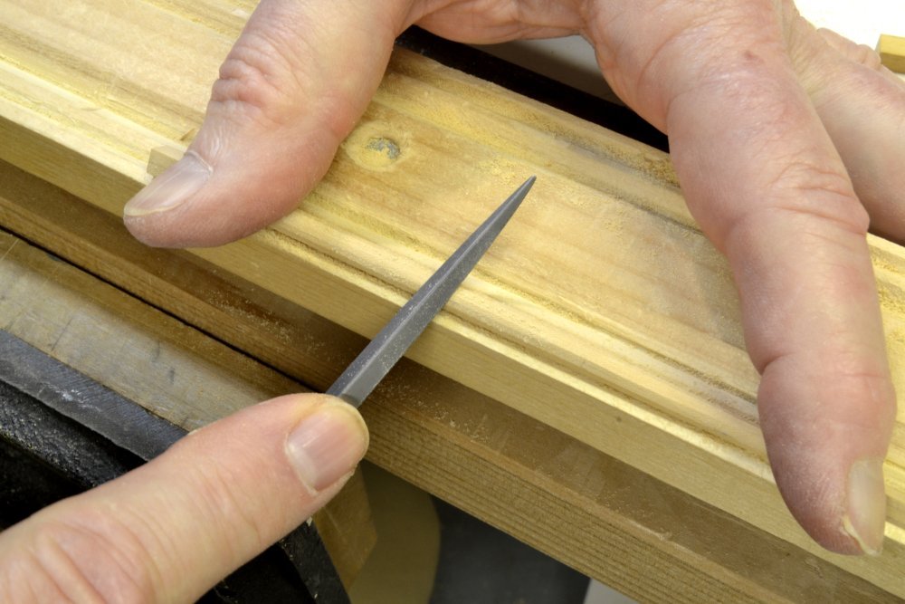
Young America - extreme clipper 1853 Part 285 – Mizzen Topmast At this stage in the model I am feeling like most of the modeling methods are well developed, with kinks worked out and reduced to standard practice. With a lot of repetitive work ahead, I believe efficiency and time saving will benefit by "mass producing" or at least grouping similar work. So far, work has been mostly sequential – to avoid tedium as well as "systemic" process problems affecting a lot of parts.. Making all the remaining masts – the mizzen topmast, the topgallants, and the royal/skysail/pole integral masts are described in this and the next part. Having these all made will allow me to reduce repeated setup time on the mill for boring matched, sized holes for the caps and the parral trusses. This work will be described later. This part describes the mizzen topmast, a repeat of earlier spar-making descriptions with some additional detail and at least one process improvement. In the first picture the sized square of the "first trim" is held in the vise to file the square of the mast head. The remaining square was then tapered - again by filing - using the fixture described in an earlier post to grip the tapered sides. Tapering these smaller spars uses more filing and less of the planing and scraping that was used on the larger pieces. Breadth of the spar was checked at each quarter frequently throughout all this shaping to conform to the specified dimensions. The next steps create a regular octagonal shape over most of the spar. Each surface is first marked with the lines of the apices of the octagonal shape. The next picture shows two tools used for this marking. The tool on the left – and its use - was described earlier. It consists of a scriber point located 7/24 of the distance between the insides of two guide pins. The tool marks a line at this proportional distance on tapered spars by holding the guides against the sides while marking. The newer tool to the right has the same configuration, but substitutes a sharp drafting lead for the scriber. This has the advantage of being easier to use, especially on small spars, but the disadvantage of having to frequently replace the lead. It is also important that the point on the lead be sharpened on center. The next picture shows this tool being used to mark lines on a small spar. These lines serve for initial roughing out of the octagonal shape. Final dimensions along the spar are refined by trial and error measurement with digital calipers. The next picture shows the fillets being filed out at the square-to-round transition at the base of the mast. This is done as the first step in creating the octagonal shape. The next picture shows the octagon being filed on to the spar. As described in an earlier post, the v-groove fixture is used to hold the piece for this work. After completing and final dimension checking, the spar is rounded as shown in the next picture. The last picture shows the finished topmast spar. Note that the hounds area is left octagonal and that the fid opening at the base has been squared and sized. The lower mast cap shown in the picture has the hole for this mast sized to fit the actual final diameter of the mast. More on that later. Ed
- 3,618 replies
-
- 34
-
-
- young america
- clipper
- (and 1 more)
-
Acrylic colours for artists
EdT replied to TomJonas's topic in Painting, finishing and weathering products and techniques
An old, dormant pastime, Maury. Ed -
Acrylic colours for artists
EdT replied to TomJonas's topic in Painting, finishing and weathering products and techniques
I have painted thousands of cast metal or epoxy molded military miniatures using acrylic artists' colors over many years, starting in 1970 when (I believe) the first acrylic designers gouache was introduced by Rowney. It was eventually discontinued, but returned later by other manufacturers. I have used the Jo Sonya product almost exclusively for many years. The finish is dead flat but may be given some gloss with acrylic medium, or other forms of artists acrylics may be used where some level of gloss is desired.. Gouache color range is extensive. Make sure it is acrylic. Some gouache resins are not waterproof. The product may be thinned as desired using water to provide washes or to build up color in multiple coats. I have found these materials to be superior to products made for modeling. I have used Vallejo, Humbrol acrylics, and other acrylic modeling paints but prefer the gouache for the pigment quality and variety of colors. As a primer, I use flat black (Rustoleum) enamel, highly thinned with a good quality solvent. The black helps highlight folds or crevices in the figure which would otherwise have to be filled with paint. The primer is brushed on and allowed to dry thoroughly. Colors are then built up from dark to light, which is facilitated by the waterproof acrylics. Finishes are durable and non-fading. Ed -
Thanks again, everyone, for all these comments and "likes." As I have said many times already, they are much appreciated and help me tremendously. Rob, I have not begun to think about future homes for any of the models, but will need to do at some point, especially for Young America, which is much too large for a place in our home. Victory fills an entire bay window behind me as I write. Naiad is essentially in storage awaiting a case. Allan, thank you. The camera, on its tripod, is an ever-present necessity and obstruction in the workshop. The white background for the model is provided by the white foamboard lining of the dust case - an essential feature in a shop that is also used for woodworking. My bench tops are white melamine-coated particle board, so to take a picture at the bench, I usually sweep the clutter away, out of the shot, and take it. Sometimes a use a sheet of Bristol board for close-ups of parts or use one of the drawings as a background. I take all pictures using the 10-second timer on the tripod-mounted camera so I can setup the shot, then put my hands in if necessary. All the pictures are taken in available light, using auto focus and aperture priority with the lens stopped down for maximum depth of field. I sometimes use a screw-on macro lens for very close-ups. White balance is a problem with the variety of lights in the shop - florescent, LED, and incandescent. As I mentioned earlier, this usually requires some postwork color correction. I probably average 200 pictures per month. It is definitely a major part of the job. Thanks for the question. Ed
- 3,618 replies
-
- 14
-
-
- young america
- clipper
- (and 1 more)
-
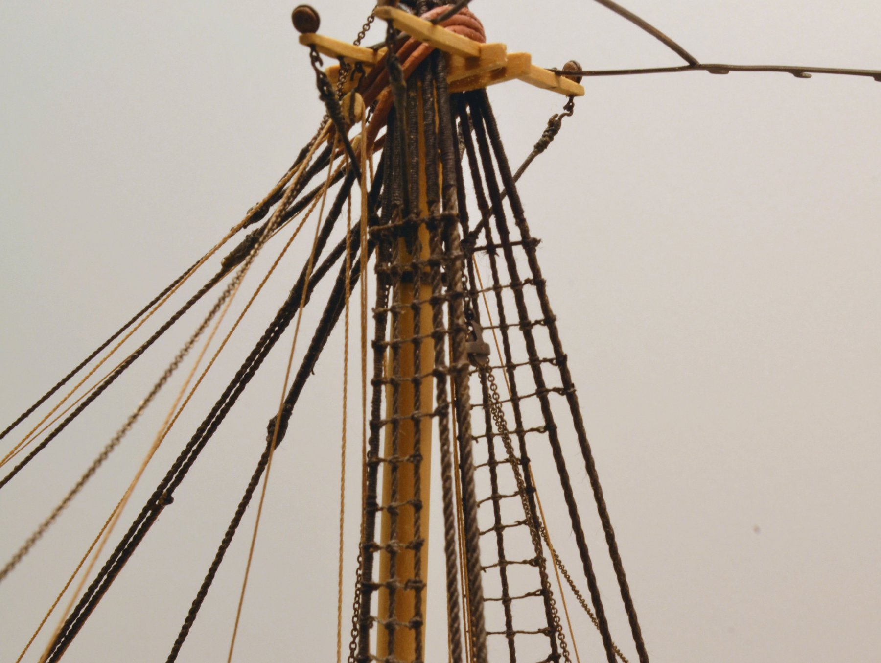
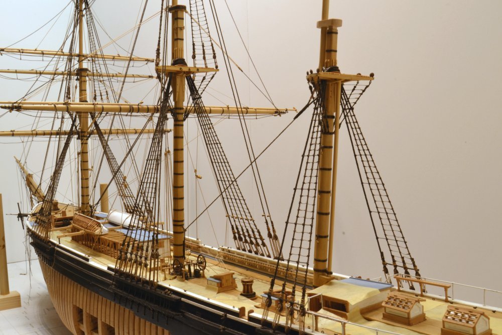
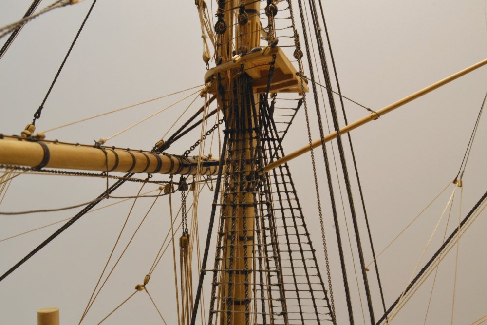
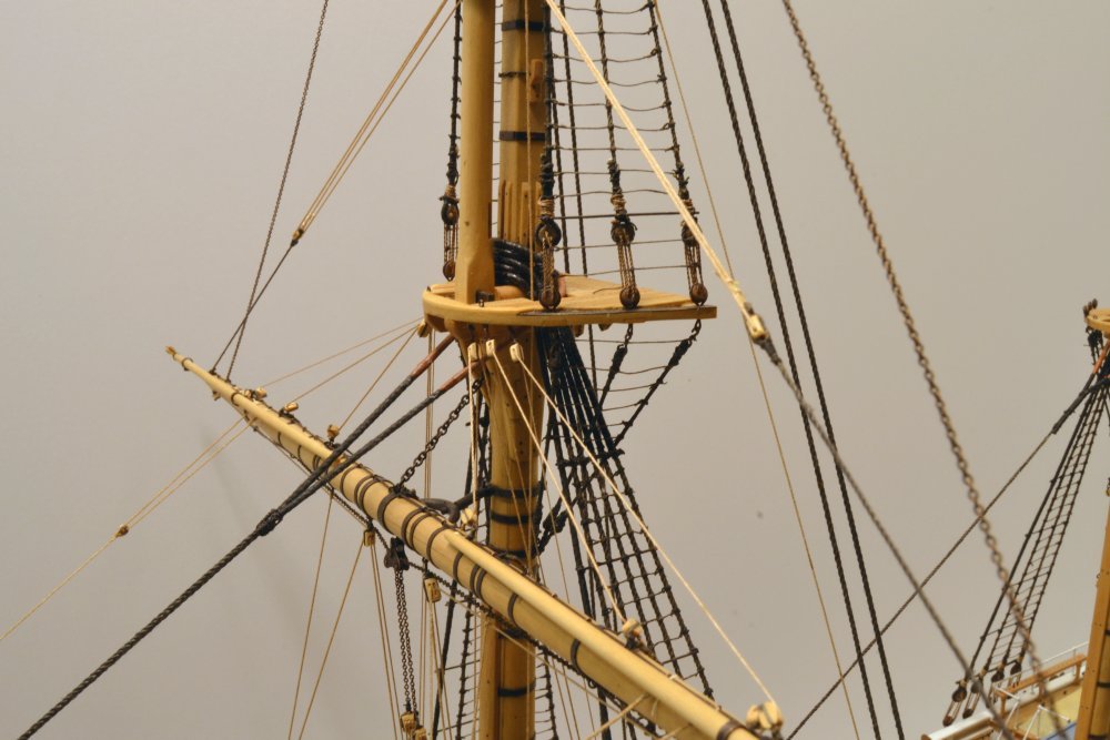
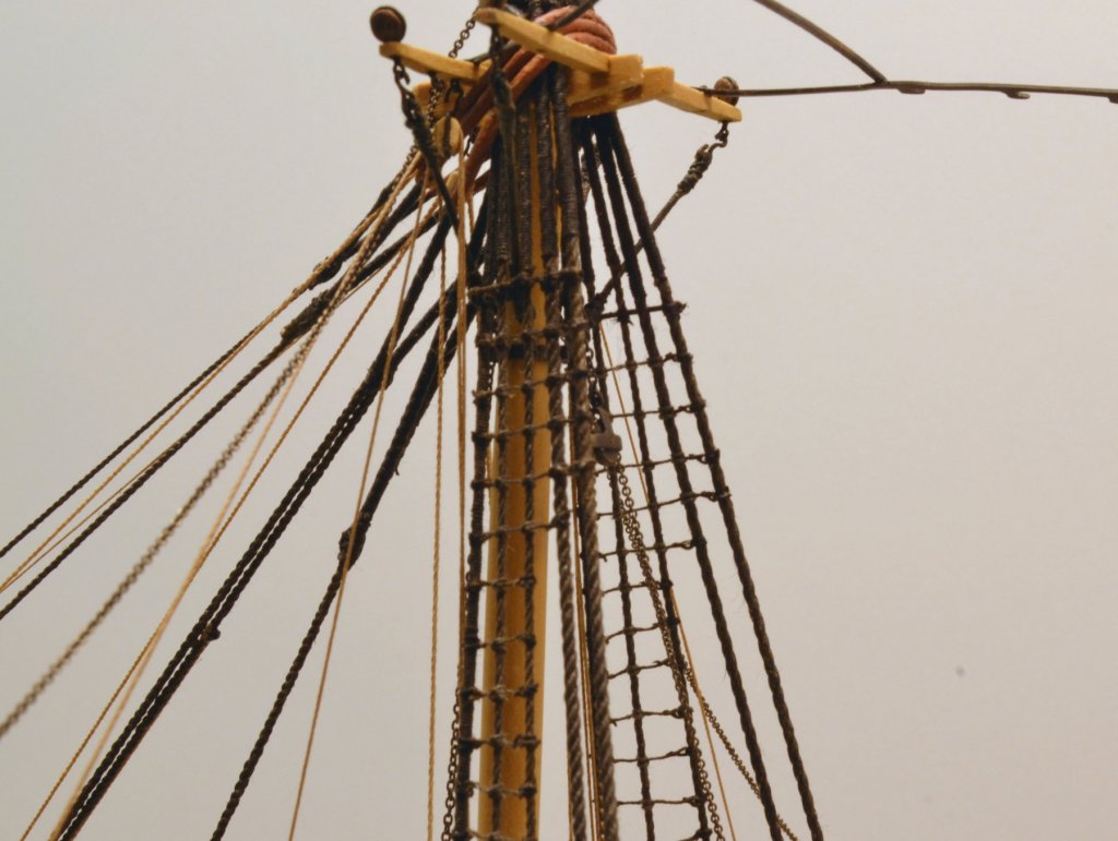
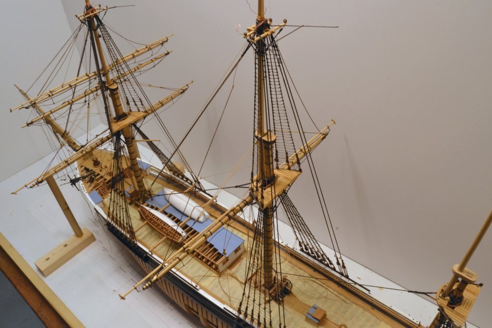
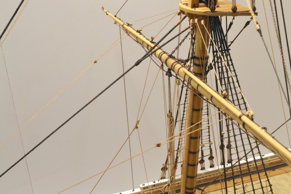
Young America - extreme clipper 1853 Part 284 – Last Post on Ratlines While there is still some further ratline work ahead, that will await further mast erection. For now, I have reached a stopping point after a few weeks work on this. Other work has been progressing and I will describe that in later posts. For now, I will just show the present status of the ratlines – and the overall model. The first picture shows the ratlines completed to this stage. Some minor replacement/rework is still needed – revealed in part on some of these pictures, but what is shown here is essentially finished. The next picture shows work below the foretop that I should have done much earlier to avoid having to tie ratlines in the congested rigging shown. The next picture shows the same work around the main top – much easier. The topmast ratlines extend across the topmast backstays under the crosstrees as shown in the next picture. The futtock ratlines here will be installed later. Finally, another view from above. The way is now open to work on the main topsail yards and other things. Ed
- 3,618 replies
-
- 49
-
-
- young america
- clipper
- (and 1 more)
-
HMS Naiad 1797 by albert - FINISHED - 1/48
EdT replied to albert's topic in - Build logs for subjects built 1751 - 1800
Fantastic work, Albert. Ed -
HMS ROYAL KATHERINE 1664 by Doris - 1/55 - CARD
EdT replied to DORIS's topic in - Build logs for subjects built 1501 - 1750
Your artistry leaves me speechless, Doris. Ed- 1,035 replies
-
- 7
-
-
- royal katherine
- ship of the line
- (and 1 more)
-
HMCSS Victoria 1855 by BANYAN - 1:72
EdT replied to BANYAN's topic in - Build logs for subjects built 1851 - 1900
Lovely details, Pat. Bravo. Ed- 1,013 replies
-
- 3
-
-
- gun dispatch vessel
- victoria
- (and 2 more)
-
Johann. these small detailed pieces are simply superb. Beautiful work. Ed
-
Thanks to everyone for comments and likes. Thanks, Druxey. That first post doesn't seem that long ago. Andy. perhaps what keeps me out of the corner is knowing that I would get no sympathy whatever. Cog, with my eyesight I can't distinguish every detail, but I like knowing it is there. Rob, I wish my time management was better. Perhaps the 4 1/2 years on this model would be less. Right now I am averaging about 2 hours per day. Thank you Peter. The high contrast photos accentuate detail - even unwanted detail. The biggest issue with work like this is clipping off the excess ends neatly. Ed
- 3,618 replies
-
- 11
-
-
- young america
- clipper
- (and 1 more)
-
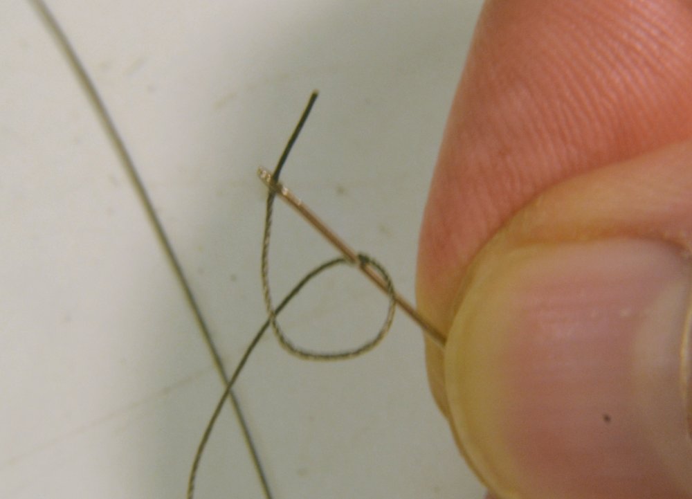
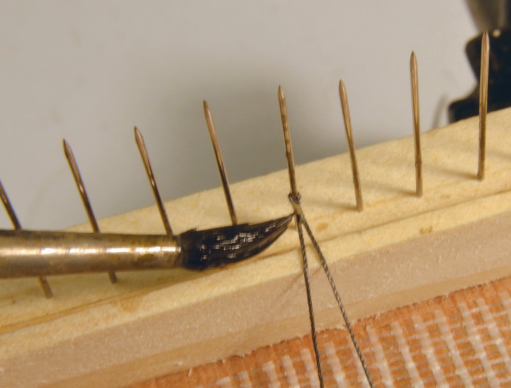
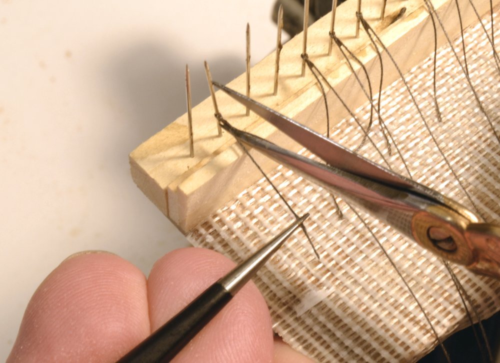
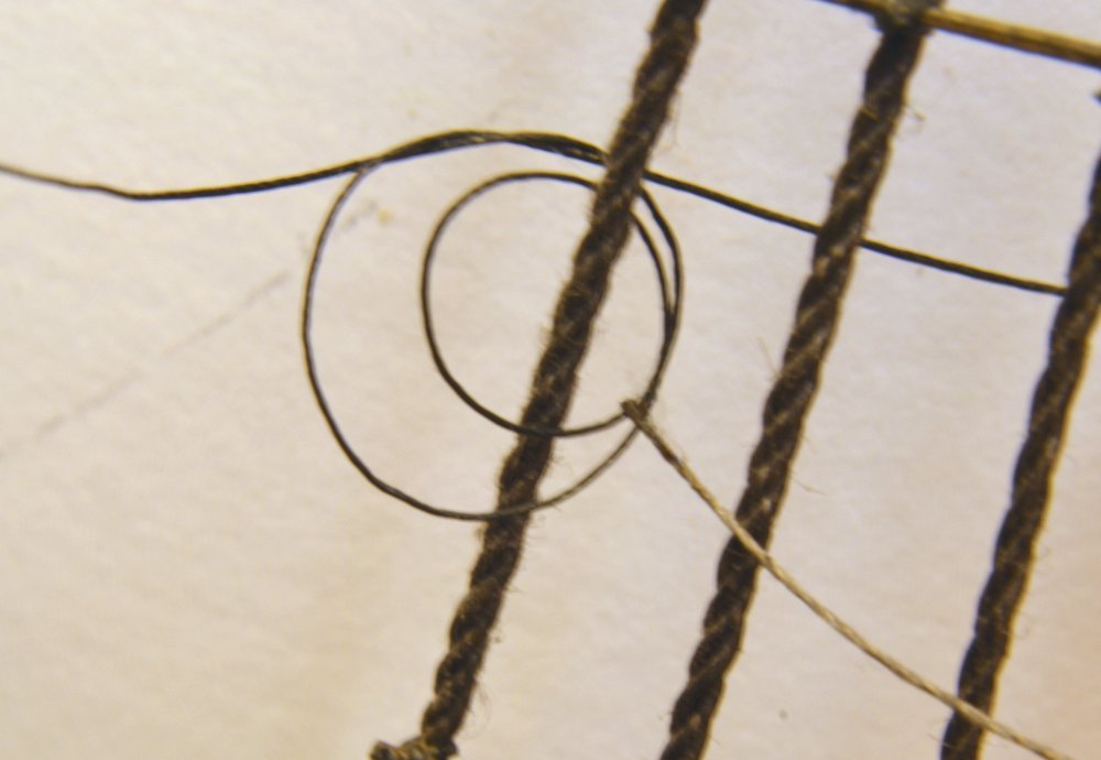
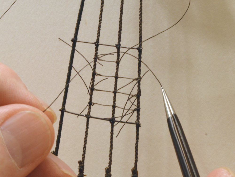
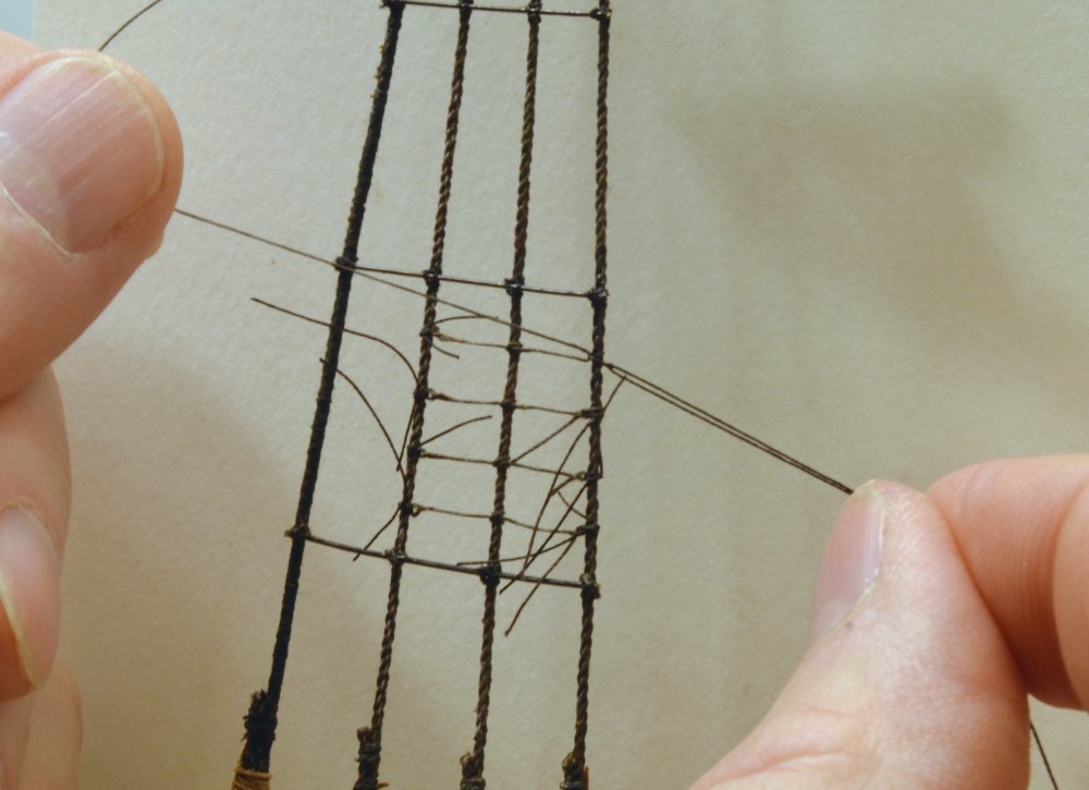
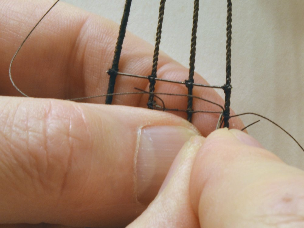
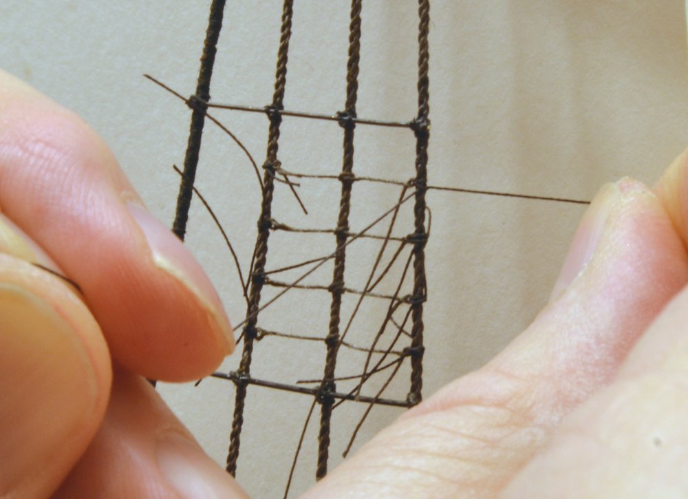
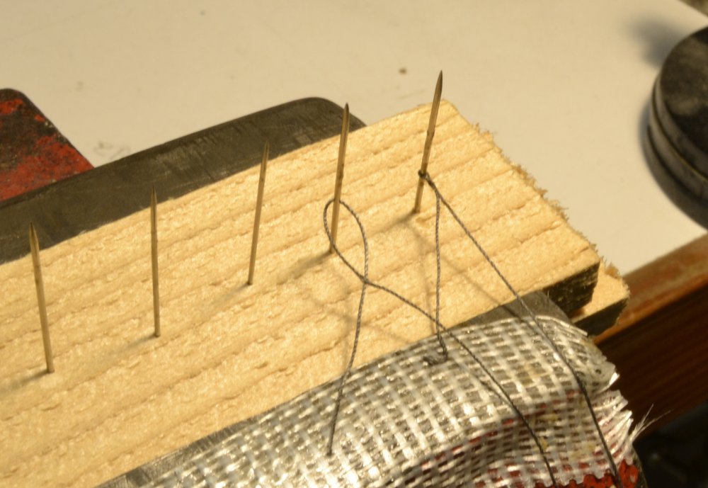
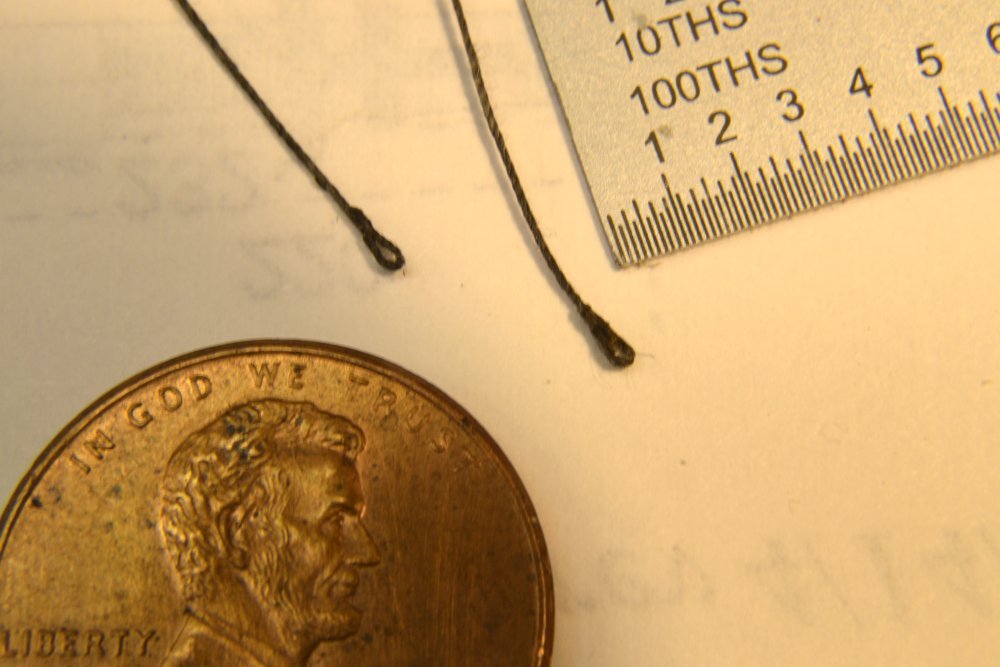
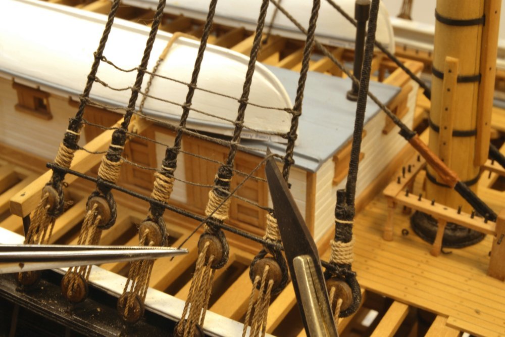
Young America - extreme clipper 1853 Part 283 – More on Ratlines There have been some questions on splicing and lashing ratlines at this scale, so the process I use is outlined below in more detail than I usually put in these posts. There are perhaps about 500 individual ratlines on the model. For the past ten days or so, I have been working diligently to get caught up with these. It is fairly easy, dull work but it can be a nightmare in the presence of other rigging - as I have learned while installing some on the fore mast after much of the surrounding rigging was in place. Not a good idea. At this stage I have settled on a process for this work that is described below. The ratlines are 1½" rope, about .007" diameter at 1:72 scale. I used No. 80 crocheting cotton for these, dyed with dilute India ink and de-fuzzed by passing twice through the flame of an alcohol burner. The ends of each ratline have eye splices that are lashed to the outer shrouds, with clove hitches on the intermediate shrouds. I used No. 100 mercerized cotton polyester thread for the lashings. One of the eye splices is put on each ratline at the workbench in batches of about 15 lines. The first step is shown below. A needle is passed through the ratline, then threaded and pulled through to form a loop. This is then placed over a pin on the splicing fixture, pulled taut and touched with slightly dilute, darkened wood glue as shown in the next picture. Both ends are held taut by pressing on two-faced carpet tape on the fixture. When the glue has completely dried, the short end is cut off as shown below. Small, sharp scissors seem to be best for this, cutting off the loose end and part of the hardened glue to simulate the shape of a splice. Finished splices are shown in the next picture from an earlier post. The spliced end is lashed to the outer shroud as shown in the next pictures. The lashing is passed through the eye and around the shroud twice, then secured with an overhand knot. When pulled tight the height may be adjusted by eye to set the correct uniform spacing. Clove hitches are then used on the intermediate shrouds. The next picture shows ratlines on the port lower mizzen shrouds. The left lashing has been secured and the center clove hitch tied. The remaining pictures show the method for forming and lashing the second eye splice. In this picture the first of two passes of lashing thread is being looped over the ratline and around the right hand shroud. An overhand knot is then tied, positioned and the ratline pulled through as shown in the next picture. The ratline is then threaded on a needle that is passed through the ratline just inside the shroud as shown next. The last picture shows the formed eye and the lashing being pulled tight. The knots are wetted with dilute glue to keep them from loosening. The ends are clipped off short to avoid entanglements with following work. When the glue has dried these ends are clipped off as close to the knot as possible. Ed

- 3,618 replies
-
- 43
-
-
- young america
- clipper
- (and 1 more)
-
That is what I call beautiful rope, Amalio. Ed
-
Lovely work as usual, Frank. The tackle looks much better now. One thing to keep in mind: the length of the tackle itself should be somewhat longer than the required length of travel to raise the centerboard to allow the full travel without the tackle becoming block on block. Ed
-
Looks like a scrap of broken chain, Rob - waiting for the cleanup crew. Ed
- 3,618 replies
-
- 3
-
-
- young america
- clipper
- (and 1 more)
-
Thank you for these comments. Scott, the clipper drawings by Bill Crothers were made, as I recall, in the 1970's. When I met with him a few years ago he was finishing up his book on masting. There are various differences from information he researched in between - mostly minor changes. Drawings and his books are still great references. Greg, I have been working on ratlines steadily over the past week It seems an endless job - and pretty tedious. I will probably be showing some of this recent work in upcoming posts, but here are three pictures from post 213 that sort of illustrate the process. The splicing fixture has been improved since then. The 2 1/2" rope for these is No. 80 crocheting cotton dyed black with dilute India Ink. One splice is made on the fixture then lashed to the shroud using finer black thread. Intermediate knots are clove hitches. The second eye splice is made in place after lashing that end by passing a needle through the rope inside the shroud. All is then sealed using diluted darkened wood glue. Although the work is repetitive, it is fairly easy to do with some practice and goes quickly. First a simple eye splice made by passing the thread through itself, pulling taut and gluing: Finished splices - one end: Removing excess fron glued second splice: Ed
- 3,618 replies
-
- 27
-
-
- young america
- clipper
- (and 1 more)
-
I expect it to be pretty much the same, Steve, but some of the smaller parts may need to be simplified and some of the sizing, for example chain, may require different representaion. Some of the smallest blocks may need upsizing. The 1:96 model is 3/4 the size of the 1:72. Most of the adaptations will be common sense decisions that you will be able to decide. ed.
- 3,618 replies
-
- 3
-
-
- young america
- clipper
- (and 1 more)
-
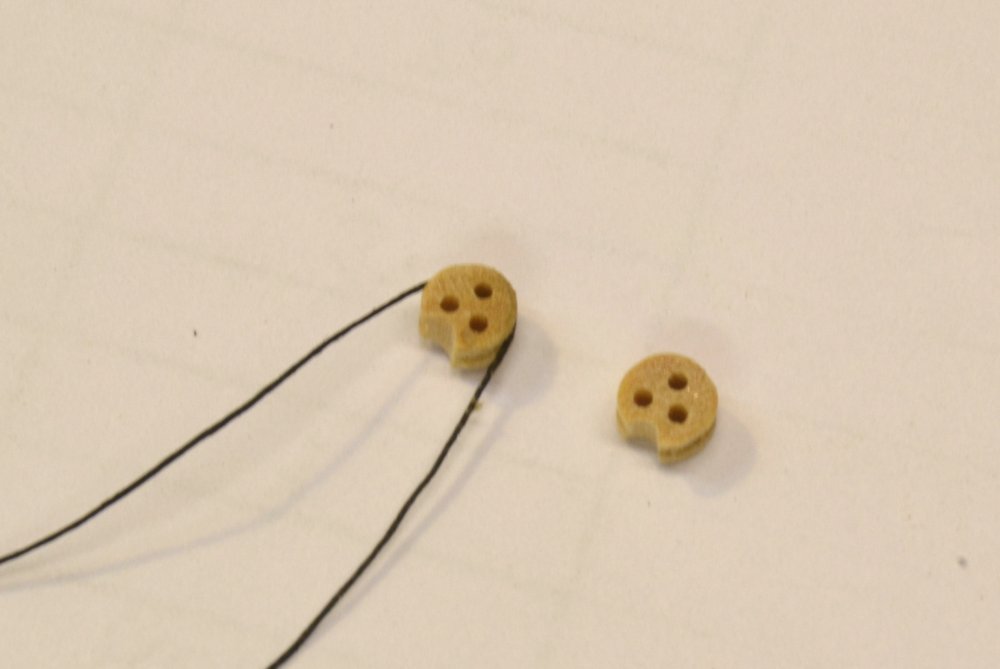
Thank you, Nils. These "fairleads" are very similar to deadeyes with their three bored holes. The groove around the outside is shallower and wider than a deadeye groove - to take the small rope lashing that holds it to the shroud. There is also a groove on the perimeter to seat the fairlead to the shroud. Here is a photo of an actual shroud fairlead and a second photo from an earlier post showing model fairleads: The holes are not easily seen in this photo due to the bright background. In this photo the lashing thread is first glued to the fairlead to make installation easier. Ed

- 3,618 replies
-
- 13
-
-
- young america
- clipper
- (and 1 more)
-
That is a very good idea, Dave. Thanks - and thanks for the compliment. Ed
- 3,618 replies
-
- 3
-
-
- young america
- clipper
- (and 1 more)
-
Thanks everyone for your responses to this post. Always a pleasure for me to see. Especially thanks for the comments and the questions. Pretty much everything but the studding sail rigging, Druxey - a decision I made early on when deciding on the level of detail to include in the hull. I wanted the rigging detail to be consistent with that - or was it just an engineer's mentality run amok? Maury, thanks. I would not fault anyone for not wanting to crawl into this rabbit hole. Fortunately there is no need to if you wish to build the model. I crawled in not really knowing if I could make it out, but after the work completed so far, including the tangle in the last post, I can begin to see light at the end of the tunnel. Now it is just execution. Thank you, Pat. I have no plans to put more work into the 1:96 POB demo model, but I have no doubt that the same rigging could be added to that smaller hull. I have given this some thought in developing the drawings and methods that are/will be included in the books. Simplifications and compromises must be made as scale gets smaller. Scale is only an issue it you set the same expectations across the range for modeling detail and perfection in all the parts. As a matter of personal objective, I think of the YA model as a whole piece, not a collection of perfect parts. To each his own. Ed
- 3,618 replies
-
- 8
-
-
- young america
- clipper
- (and 1 more)
-
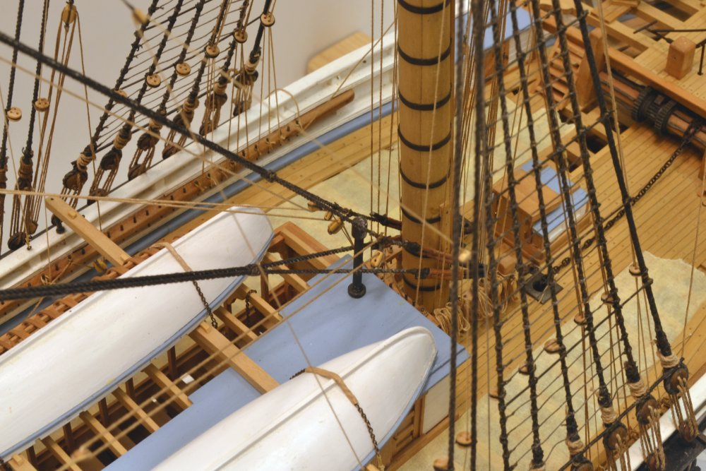
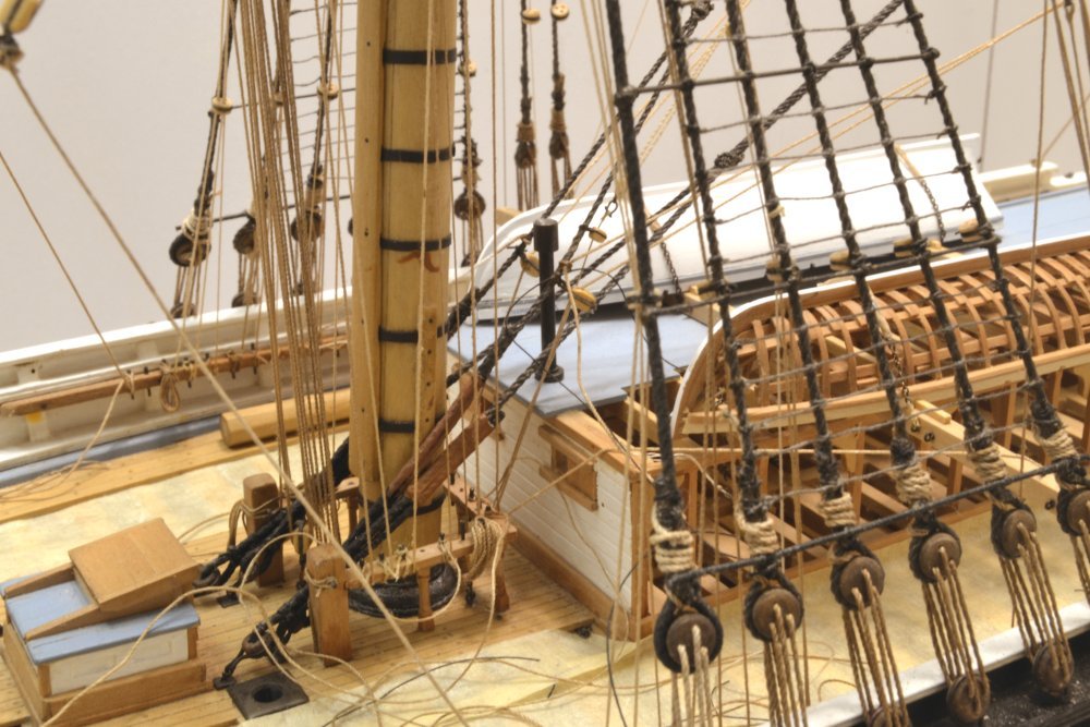
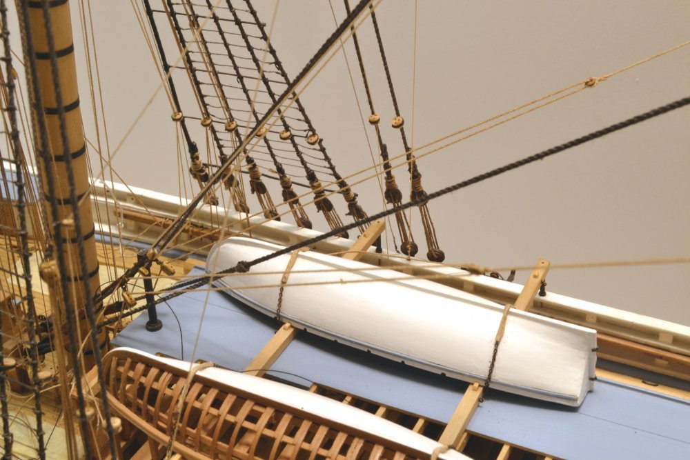
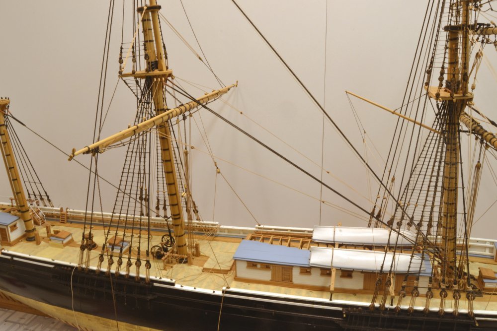
Young America - extreme clipper 1853 Part 282 – Main Yard Rigging 3 Bowlines were used to control the leeches on large sails. When the sails were bent, bowline bridles were lashed to cringles on the sides (leeches) of the sails. On the model without sails, the bridles are tied off to the jackstays where they would be accessible to topmen when rigging the sail. The first picture shows the bowline gear. The bowline bridles, in this case two-legged, have eyes spliced in each end and pass through bullseyes at one end of each "lizard". The bowlines, themselves, pass through the bullseyes at the opposite ends. The standing ends of the bowlines are made fast to the lower ends of the topmast stays, pass through the lizard eyes, and are belayed on the foremast fife rail. To avoid the falls rubbing on the roof of the main cabin, the two lead blocks shown in the picture were secured to the stay below the standing end fastening. The attachment of the bridles and the upper ends of the lizards are shown in the next picture. These lines serve well to square the model main yard and assist in holding it down. The bridles are tied off at locations on the yard near where the cringles on the sail would be when it was raised as a rolled up package. These and the other lines would then be fastened before the sail was loosed. I have expected that belaying lines in the confined space between the cabin and fife rail would be one of the major rigging challenges on the model. I wasn't disappointed. The next three pictures showing this work and the belaying of the main topmast staysail downhauler illustrate the problem. First, the staysail halyard and downhauler were rigged. The halyard may be seen running parallel and below the topmast stay. Its lower block is shackled to the downhauler that passes through a smaller lead block on the stay and belays on the athwartship fife rail just forward of the cabin. The two bowline lead blocks are also fastened to the stay legs below the downhauler block. These are then also belayed on the fife rail. The next picture shows the tangle of lines involved and the small working space. Apart from the difficulties of belaying lines in this small space with interferences from the shrouds and other obstacles, the two bowlines had to be tensioned together to hold the yard square. Both were looped under their pins, adjusted to square the yard, then each belayed on top. Finally, another view of the work in progress. This job took special tools, quite a few hours, and a number of expletives. The last picture shows this stage of the main yard rigging completed. You may note in this picture that the shroud lanyards that have been seen loose in previous pictures have now been wrapped and secured. Some rope coils have begun to be fitted forward where belaying is complete. There is still much of this to do and also quite a bit of ratline work on the upper main mast and mizzen. Ed
- 3,618 replies
-
- 38
-
-
- young america
- clipper
- (and 1 more)
-
I believe that nitrocelluose is laquer resin. It makes a good sanding sealer because it is hard. Will check and advise if incorrect. Ed