


Wintergreen
-
Posts
1,002 -
Joined
-
Last visited
Content Type
Profiles
Forums
Gallery
Events
Everything posted by Wintergreen
-
iieeeewww, those gory buckets of ...remnants. Spot on! Even the smudges on the decking 🙂 And that small, green tarp wrapped over something. All wrinkely and worn. So good. Didn't see that before. Keep it up!
-
That makes sense @wefalck, definitely no tar (self explanatory in fact). Albeit, about the kåg, it was a work boat so I have little faith in that they were meticulously kept. Maybe I'll give them a light wash. But before any painting there is a rubrail to add. After that comes variious hardware and the rudder.
-
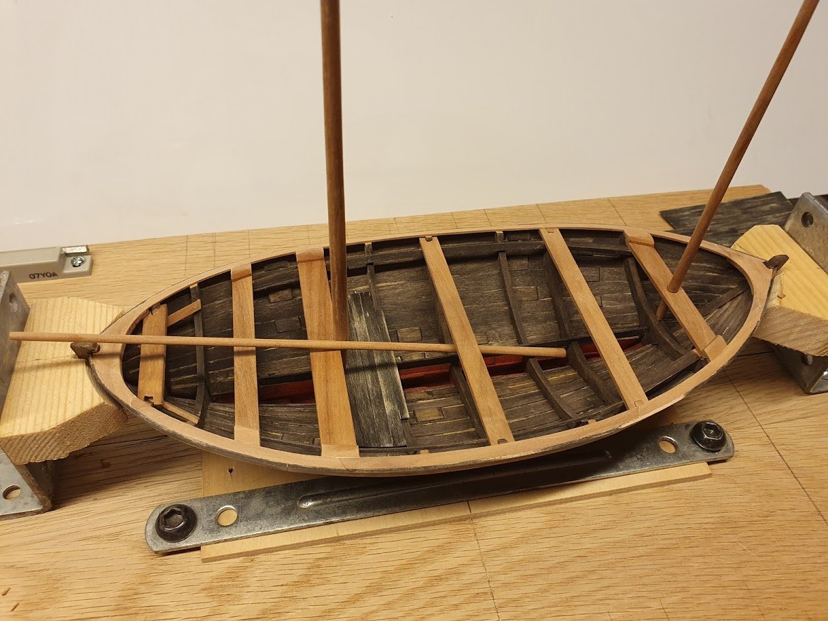
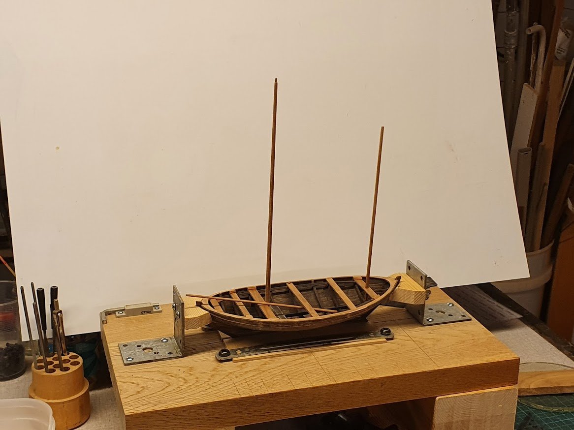
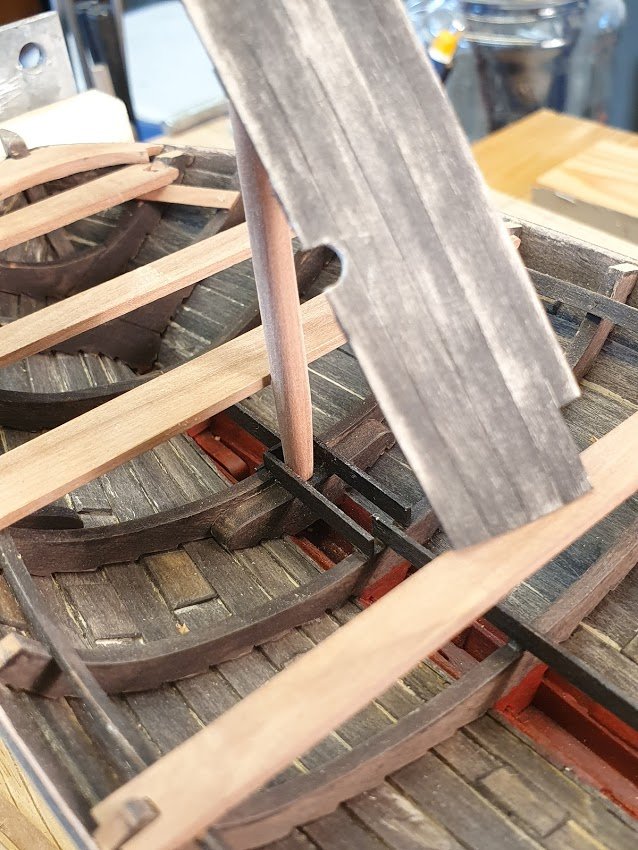
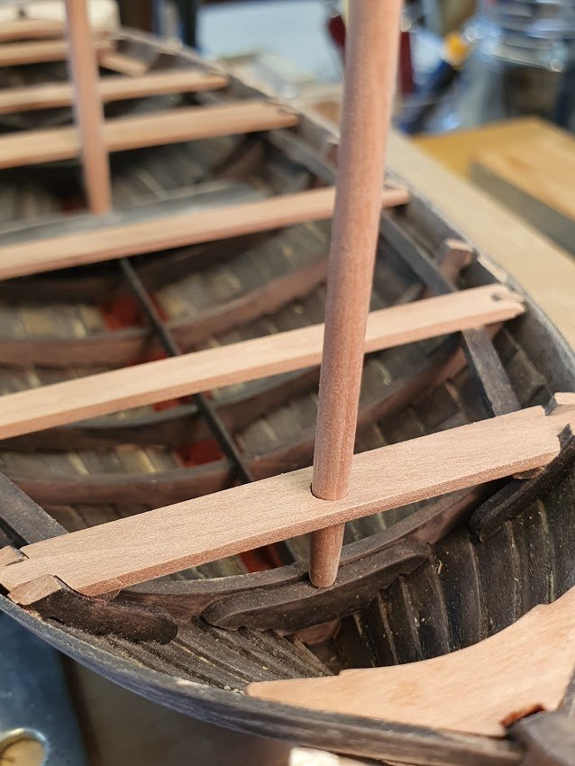
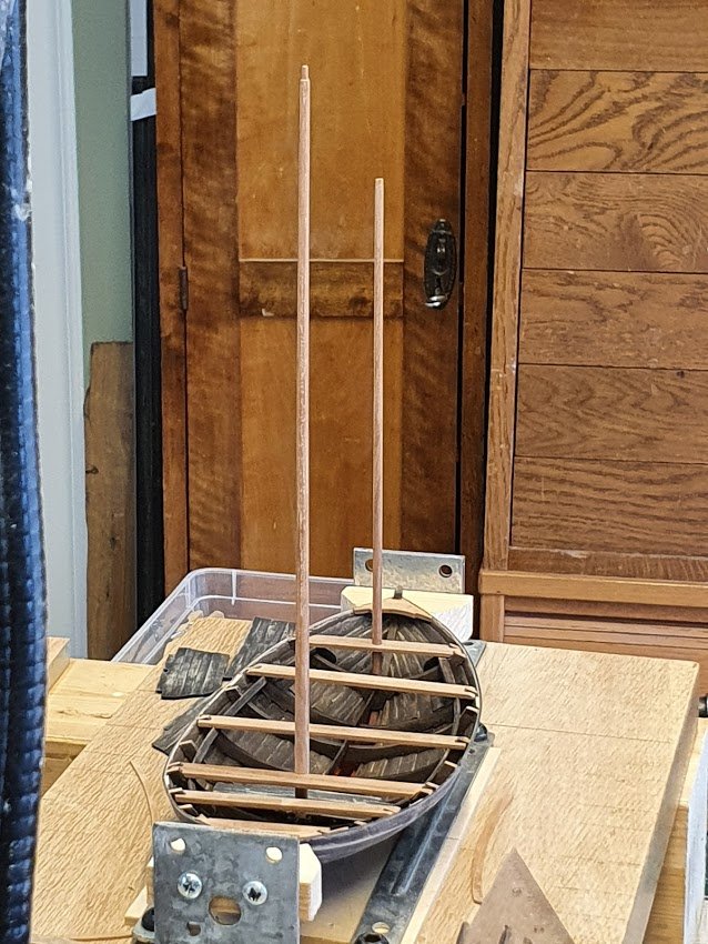
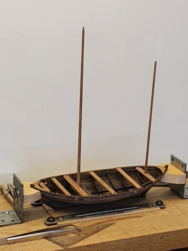
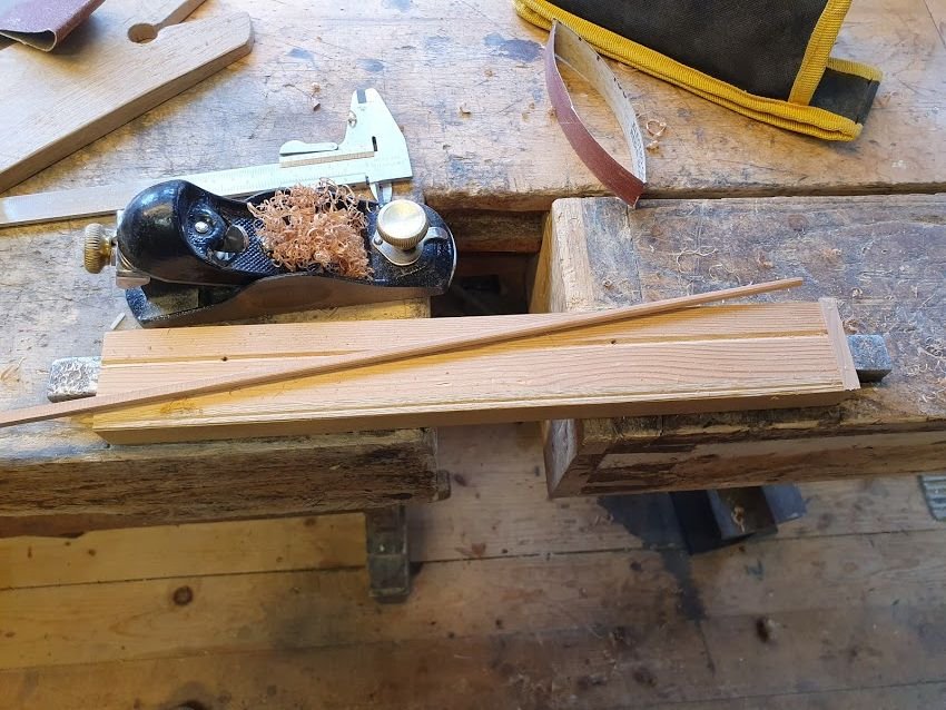
Building continues. Focus last couple of days was to permanently glue the inwale. But before that the masts needed to dealt with. The fore mast sits at the after edge of the main thwart and the mizzen mast is just stepped through a hole in the last thwart. Both masts have a peg or tenon at the bottom end. Both masts stands unsupported by shrouds and stays. Dimension are as follows. Main mast - length 25', diam at thwart height 5½", diam at top 3". That translates to 254 mm x 4,7 mm and 2,5mm. Mizzen mast - length 19', diam at thwart 4". Translates to roughly 192mm x 3,3mm. Made a small jig to accommodate easier planing. This is actually a quite good fit 🙂 Don't mind the dust, it is after all Work In Progress 😉 Trying out main mast support. After the supporting semi circle is filed in the thwart masts are both plumb and at correct angle. Main mast almost vertical and mizzen a slight lean aft. Now I could fasten the thwarts and glue the inwale in place. As mentioned before, the foremost thwart and the one in the middle are removable. I even made the jib boom while I was at it, 16½' long and thin. Only used in lighter winds. As can be seen I haven't painted the details and maybe I won't. I kind of like the contrast of the natural apple to the rugged hull. What do my followers think? And as always, thanks for likes and comment! Much appreciated 🙂
- 240 replies
-
- 14
-

-
John, Tony and Jim - thank you and welcome to this show of "slow TV" 😄 Tony, good of you to mention the use of same CAD sw. I'll remember to add the specific features I use and all others will have to adapt that to their preferred CAD sw. Yes Jim, the ship is quite big and at 1:30 the hull will be almost 870 mm with a breadth of 210 mm. I figure it will be quite handy to build. Not too small and not too big. And my previous to boats are at 1:30 also, the Regina and the kåg. Speaking og the kåg, better head out to the shop and continue... Cheers!
-
Quite impressive work at 1:48 on a ship that is just above 40' long between perpendiculars. I guess they were almost 50' LOD? And two at the same time, wow. Edit. That peculiar stern... it looks inspired by Asian boats. Do you happen to know why they have that striking feature? Keep it up!
-
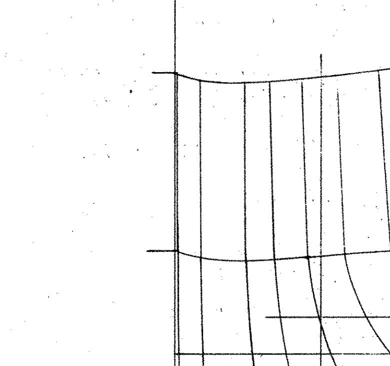
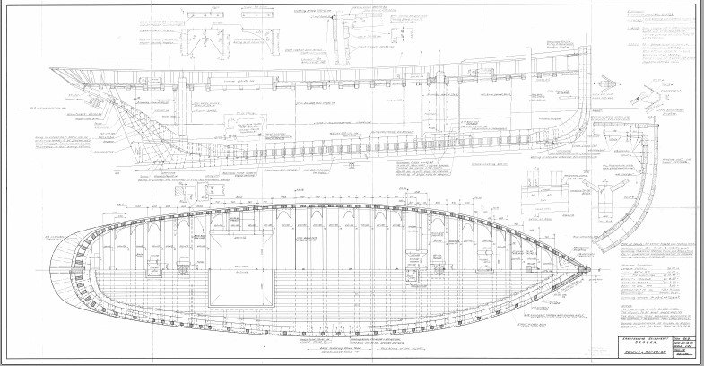
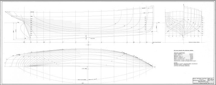
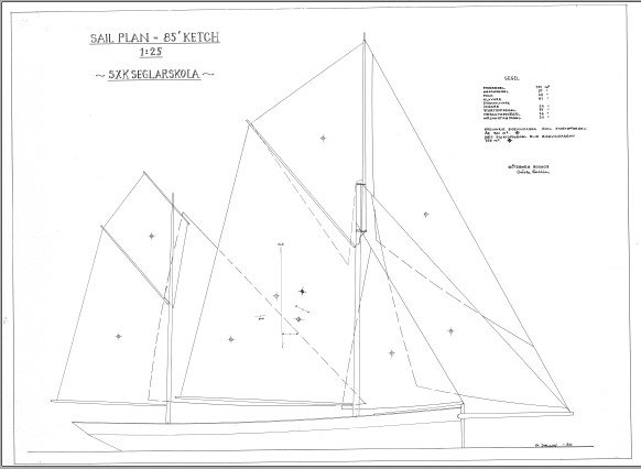
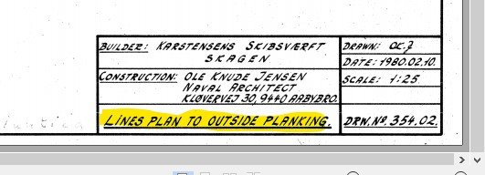
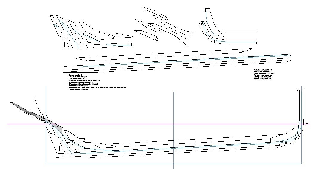
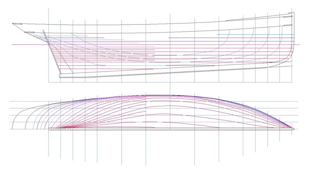
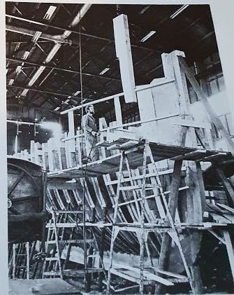
1. Plans and drafting I will not delve into too much detail about this process, instead I suggest anyone interested to have a look in Waynes document. What I will do is to point out my own challenges, retakes, and mistakes. That’ll be fun (they said) 😉 As previously mentioned, the plans are scanned originals in PDF format. Through some online service I had them converted to PNG, which I understand is the desired format (after BMP) for images with great detail. Both PNG and BMP are uncompressed formats, therefore retaining sharp images even when blown up beyond full scale. The CAD software I use is Turbo CAD Deluxe version 20. It is a reasonable priced software for those without too big ambitions. It says it can handle 3D but I’ve never got my head around using it so I stay in 2 dimensions. These are the plans I got: Lines plan with body, sheer and half breadth plans. Construction drawing showing all major details as frames, deck beams, mast supports, deck and side planking, deck openings and what not. Sail plan Finally, a big PDF with mast and hardware. Several pages long. The process of drafting is to take the lines plan first, load into your CAD software and trace all lines of the sheer and body part and leave out the half breadth plan with all its waterlines. Make sure you have the loaded image in correct size. It usually takes a little fiddling about. I used the length between perpendiculars, because I couldn’t really understand the body plan. More on that later… Next you create a new half breadth plan from your traced body and sheer. Corrections need to be made when you see uneven waterlines, and these corrections propagate back through the body plan all the way to the sheer plan. When you are satisfied dump the body plan and all corresponding station lines on the sheer plan. Add new stations and draft a new body plan. Easy peacy. I then took the sheer plan into a new drawing and added the image of the construction plan. The first goal was to create the center line with keel, false keel, keelson, stem, stem pieces, stern, deadwood and all that. I noted that the two drawings weren’t too far off one another which was good. On the construction plan the rabbet was presented and so I added that to my center line. I took a while to disassemble the structure. One challenge when using the polyline to trace parts is that what looks like a piece is actually a void. Like the small triangular deadwood piece closest to the inner sternpost. Such things become obvious when you explode your drawing. I keep the perpendiculars and waterline to always have a common reference point when moving between drawings. Next I was to start drafting al frames, 47 all in all. The first one sits at the sternpost, like in this picture. The last frame sits at the junction between the keel and the stem. Forward of that is just bollard timbers, which I don’t really know how to fasten to the hull. The stern is made up of every so much timber there can be. The square-ish timber in the lower left is the fashion piece rising up from the sternpost. Just as I was about to start with the frames I came to a full stop. Something wasn’t quite right. To loft frames one uses the half breadth plan and the sheer plan. The half breadth plan gives you the width of each frame at any given waterline and the sheer gives you the height at any given station/frame line. However, when I was to start with the foremost frame (because they are simple) things didn’t add up. I couldn’t get the waterlines to create a frame for me and I also lacked the rabbet line. Suddenly one thing caught my attention. This is a close up of the stem. Notice how the waterlines all meet the stem very far forward? The only reasonable reason I could think of is that instead of waterlines depicting the shape at the inside of the planking all lines were of the outside! Sure enough, what do you say – sometimes your eyes clouds your vision? Yellow highlighted by me. Say no more. That’s why the waterlines come all the way forward. And also my body plan needs to be re-done. Sigh. But like a chain event I suddenly understood why I had troubles with the body plan. This is a magnification of a part of the body plan. The vertical, straight leftmost line is the square that defines the “body”. But no station goes all the way out, why? Simply because the extreme breadth of the ship falls between two station lines. Not like on old drawings where station 0 is at the extreme breadth. Some things are just plain obvious once you revisit them 😉 How to proceed? First I need to re-trace the body plan and make a new half breadth plan. When that is done I can take the body plan and do a line copy of each station at 65 mm inwards. 65 mm is the thickness of the planking. With this new body plan I can then make a new half breadth plan. Just doing a straight line-copy enters a slight error because the inner line is a tiny bit smaller. Think circles inside circles. I will play around in my CAD sw to see if I can remedy this. And when that is done - Then I can start lofting frames! Why didn’t the draftsman just draw to the inside of planking? Probably because the lines come from Gratitude, the sister ship, and that they measured her up to create drawings for Atlantica.

-
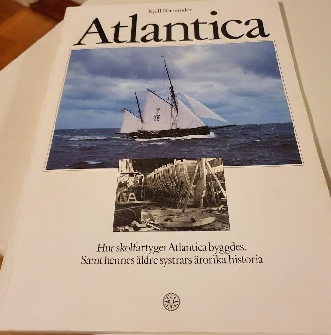
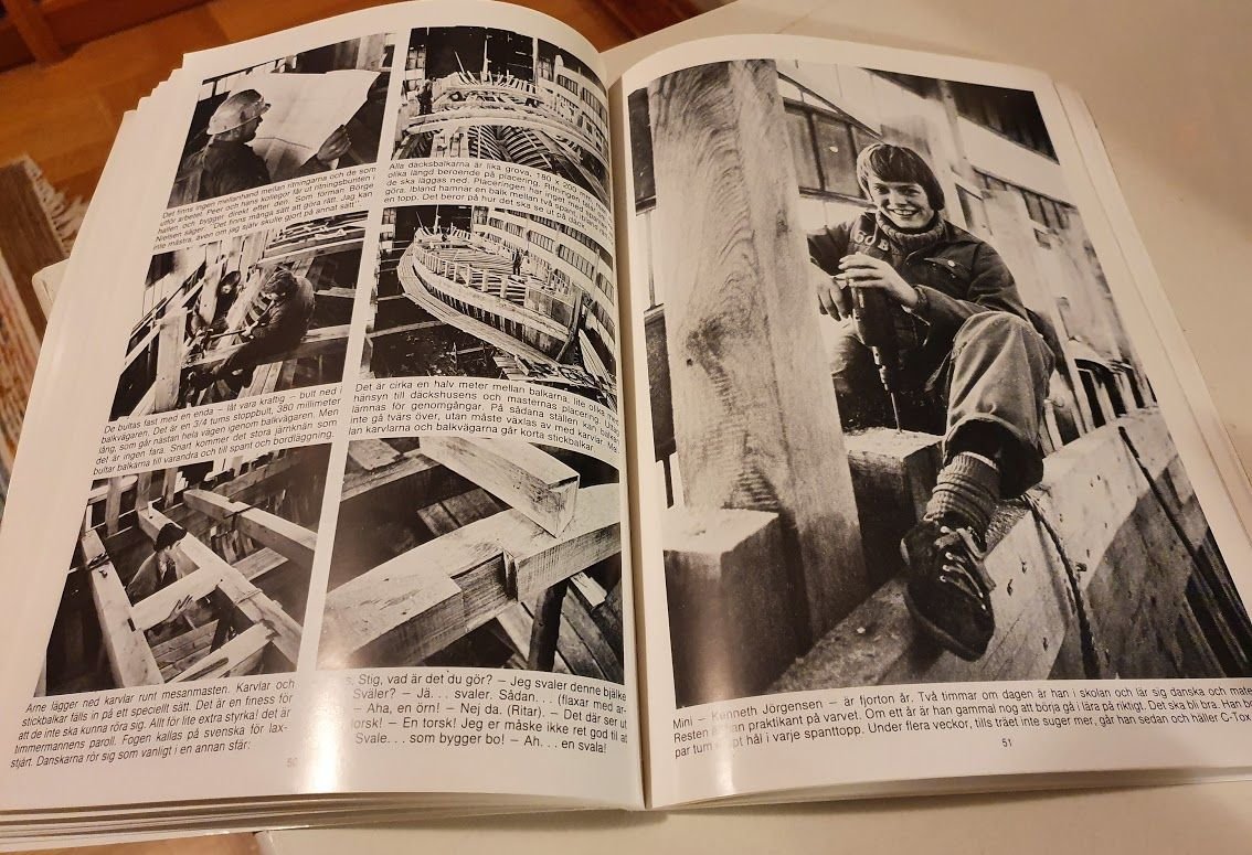
Preface §1 Expectation management It will be quite some time before any sawdust is made here, probably not before late fall. If you wonder when that is, well, that is October where I’m located at about 58 degrees north. Maybe already in 2021...we will see… §2 Pogress To quote @mtaylor: “The shipwright is slow, but the wood is patient." For you as an audience, I urge you to stack up properly with fizzy drinks and popcorn, because this will take some time. However, there are a couple more boats I like to build down the line; hence this build will not take forever, hopefully. §3 The builder - me Just on the upside of half a century old, maintaining a full time day job, summer holidays spent sailing, managing five to seven kids (or actually young adults now) and half a handful of grand kids I will disappear from time to time. See §2. §4 The captain is always right. Period. §5 In the unlikely event that the Captain is wrong – refer to §4. §6 The ship When investing so much time and effort into any project there needs to be something that makes you “tick”. There is no shortage of plans and kits of almost any kind of ship. Af Chapman comes to mind, but he will appear later in my boat building career. We have a plethora of leisure crafts, mainly small. Our Swedish constructors didn’t draw them like Fifie of Scotland, GL Watson or NG Herreshoff, the Wizard from Bristol RI. My mind finally went for Atlantica. Atlantica is a gaff rigged ketch of English smack heritage. Built in Denmark and launched 1980. The main mast is cutter rigged, meaning it has more than one head stay. It also has a bowsprit. More details and specifications for the ship, see below. The ship is in full service today as a sail training vessel owned and maintained by SXK Seglarskola (SXK Sailing School) which is a sub-branch of the Swedish Cruising Association - SXK (Svenska Kryssarklubben). More information about the Sailing School can be found here: http://www.sxkseglarskola.se/ The site is in Swedish but use Chrome browser and Google translate. The site translates really well. Needless to say I’m a member of said Cruising association and have know of Atlantica and her sisters for a long time. §7 Type of ship – English smack For some reason I’ve been attracted to this type of hull form, mostly known as a pilot cutter. It has a straight, almost vertical stem, a keel that slopes considerably from stem to stern, a large rudder and either a cut of transom or rounded one. The hull is quite narrow with one mast flying a gaff main sail and topsail. Add to that three headsails and a retractable bowsprit and it makes a handsome vessel. The hull and sail area makes for a fast and seaworthy vessel, which was a demand for piloting. It was a race to get to the merchant ships, first come – first served, any day of the year in any weather. The smack was used in dredging and fishing and was very similar in hull form to the pilot cutter because it also needed speed under sail. First, it takes speed to be able to tow the dredger. From what I’ve read it needs to be above 2 knots. Secondly, when fishing is done, the race was to get home first and land the best deals on the fish market. As with any evolution the smack was not so big from the beginning but grew over time. When the boom grew too large they went from cutter rigged to be ketch rigged. However, as a type, they weren’t that big, usually under 75’ or ca 25 m length on deck. In their hay-day at the end of 1880 the smacks were counted in thousands. 1887 there were just above 3000 registered smacks sailing out of Grimsby, Hull and Brixham. At the turn of the century Grimsby had only 34 left, Hull none. What was the reason for the quick decline? The industrial revolution with steam powered boats swiftly killed the sail powered competition. Back to sailing, a smack usually had a crew of four to five men and a boy, hence the boats could not grew too large. · The ships boy also with cooking duties. Signing on at 12 years of age. Apprentice for 5 to 7 years. Did not get paid usually. · Deck hand, also an apprentice. Had some pay, but not much. · Third hand, an able seaman that was given responsible for watches alone. · First mate, captains right hand. Could take full responsible for the ship. · Master, or captain. Answered only to God when at sea and when in port answered to the ship owner. §8 The ship – Atlantica The name is from one of the sponsors, an insurance company. She is built on the lines of her sister ship Gratitude, albeit a fair bit bigger. Again, see http://www.sxkseglarskola.se/ and menu item “Fartygen”. Gratitude is the real deal. She originates from Lowestoft, after her fishing career sold to Sweden and rebuild for cargo carrying. Atlantica, main specifcations Length on deck: 85’ or 26,2 m Length on spars: - Breadth moulded: 20½’ or 6,27 m Breadth extreme: 21’ or 6,4 m Depth: 10½’ or 3,2 m Sail area: 5810 sqf or 540 sqm Displacement: 134 tonnes No of bunks: 32 Building material: oak on oak with laid deck of keruing §9 Plans and other sources In short - a book and a bunch of PDFs’. Why, or where I got the book I can’t remember. I used it to spice up the hull of Regina (see my signature), my previous build back in early 1990, that I know. The book is in all essential a build log but in printed format and from 1980 well before internet forums. It is full of b/w images and short descriptions to each picture. What about plans then? Yes, after a fairly short search I was directed to a fellow model builder. He was involved in the process of the Atlantica build and had gained access to all relevant plans as scanned to PDF. He sent me the lot free of charge! To show my gratitude I donated a sum for the new main mast of Gratitude. The mast came tumbling down when out on an autumn sail this last fall. No one was hurt and not too much damage either bar the mast. With the help of CAD I have already started to draft the ship. I use Wayne Kempsons’ treatise on “Drafting ship plans in CAD” as a guide. See https://thenrg.org/resources/Documents/articles/DraftingShipPlansInCAD.pdf For the actual layout I will look at the plans from EdTs’ book Naiad. §10 It feels good to end the preface in double figures Tools and equipment might be of interest. At the moment I do not own a miniature table saw, no small lathe or a fancy milling station. But what I do have is a full size jointer, a full size planer, a full size (2 m) band saw, full size table saw that can take blades of 12” diameter, a wood lathe and a drill press. The lathe can be converted to a disc sander and a thickness sander and for the table saw I will source some thin blade, probably 1,5 mm to try to mill delicate planks. Fall back solution will be a fine tooth blade for the band saw and then a couple of runs through the thickness sander. In the future I might buy me a Proxxon table saw since the Byrnes one is out of reach with VAT and shipping. Until then I’ll make do with what I have. In addition to that I have a cupboard of ordinary carpenters hand tools. So it will be down to basic skills and a lot of trial and errors during this build. Let the work begin! Index 1. Plans and drafting 1.1. Preparing for lofting frames 1.2. Frame lofting party
-
Blind me! I thought the big schackel was a challenge and then there is an even smaller one linked to the chain. Just wow! Splendid work!
-
And I thought that the holiday season was well over? How wrong was I? A perfectionist may dislike the exterior hull with all the creases and unevenness, but to my eye that looks quite perfect. It looks like the ship has been in commission for quite some time and that the hull has been painted and repainted due to wear and tear. Great look actually! Keep it up!
-
Nice progress Tom! Maybe there is not much details and hardware to add, but what you add really looks spiffy and up to the task. The skylight is very probable if this was a pleasure craft. 🙂 Keep it up!
-
How to simplyfi the build of a large ship?
Wintergreen replied to ubjs's topic in Wood ship model kits
Hello ubjs, I read your question a bit up about gluing two stringers 4x8mm. These are for reinforcing the structure. About the bend downwards, as long as the bulkheads and keel are well supported it is no problem to force the stringers down. Glue them at the same time and add some weight to keep them in place. And how do I know this? Well, I did build Billings Wasa back in 1985. It took me 4 or 5 years. A thought on doing it more simple? Just add the lower masts, as it is on show in the WASA Museum. That way you will still have some striking rigging, but not too much of it. And as others have stated - it's all up to you! There are no wrongs or donts here. Do as you please 🙂 -
You should be! I know I would
-
Man! That is just excellent! I really like your detailing and that rusty chimney looks any part as real as the true piece. Keep it up!
-
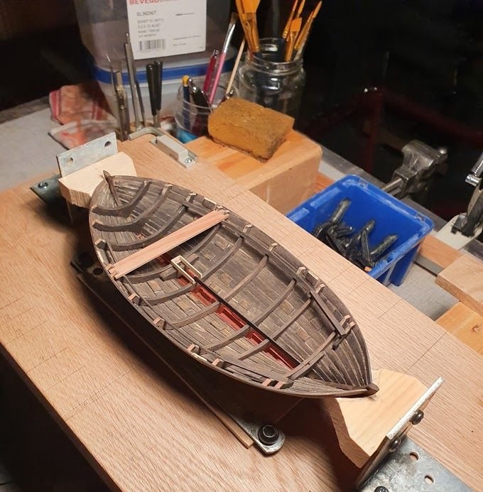
Here again. Time for another little update. Mark and Vaddoc - thanks for your support. I'll check with the admiral if there are any jewels to support my vessel. Kind of a patreon if so, right? Today I managed to produce six pieces (not of eight) but of railing. Is it called railing btw? Anyway, and previous to that the stem and stern hooks was made. I think the forward piece is called a breast hook, but what is the stern piece called? A fiddly process since nothing is square. The process of manufacture included card templates of every piece and a lot of sanding and filing. To get a good snug fit every piece it cut over sized and then the outer edge is trimmed to perfection. After that the piece is cut to width. In this case ca 3mm, which believe it or not is still over sized. The book and drawing calls for a railing of 2". At 1:30 that is less than 2mm. But sometimes I can't really be bothered. If it looks good to me. It stays. Only the breast hook and stern piece is glued and pinned in place. The railing just rests on the frame tops. I might also have a word with the shipwright since I'm not overly happy with the mess he leaves in his wake... About tools, that sturdy hand-vice is soo perfect for holding all these itsy bitsy flimsy pieces. It's quite heavy which gives a good support to any movement. Before I used it I hade to file down the jaws because they left a checkered marking on the clamped piece. Before we part for today, thank you guys for comments and likes! Much appreciated 🙂
- 240 replies
-
- 13
-
-
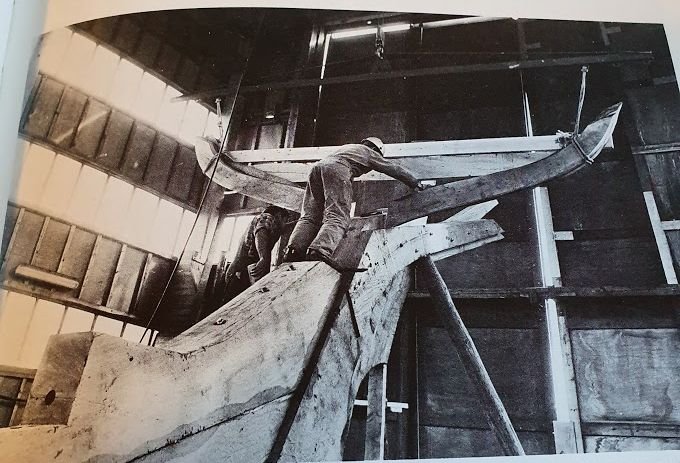
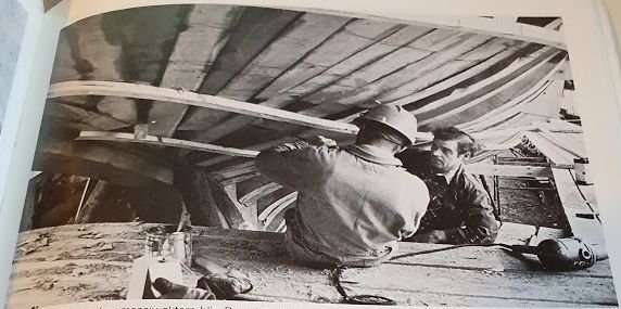
About raising and lowering the mast. My understanding is that it was done like the midsummers pole, put the lower end towards the stop and then walk under it successively raising it. Like in this picture. It's the same procedure described for my 19th century boat as well.

- 179 replies
-
- 5
-
-
- longship
- Helga Holm
- (and 1 more)
-
Looks good bolin. About the stain. On a test piece you can always play with number of coats and also what a light sanding does to the effect of weathering. Anyway, keep it up!
-
I would say that your trials and tribulations on this planking stuff is paying off now. Looks really good! (then you can add, "yeah, from a distance a dark night, lol") No, seriously, it looks good. Well done Vaddoc. Keep it up!
-
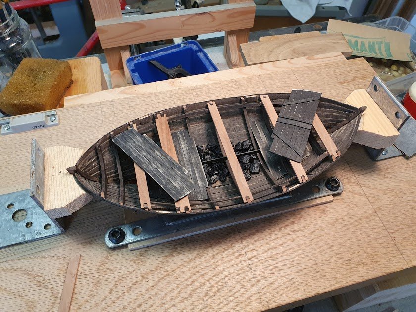
@wefalck Thanks for you input. Maybe I got the figures wrong. 12 ml (a little less than a table spoon) I can definitely fit under the boards. Anyway, it's just for show and not authenticity 😉
-
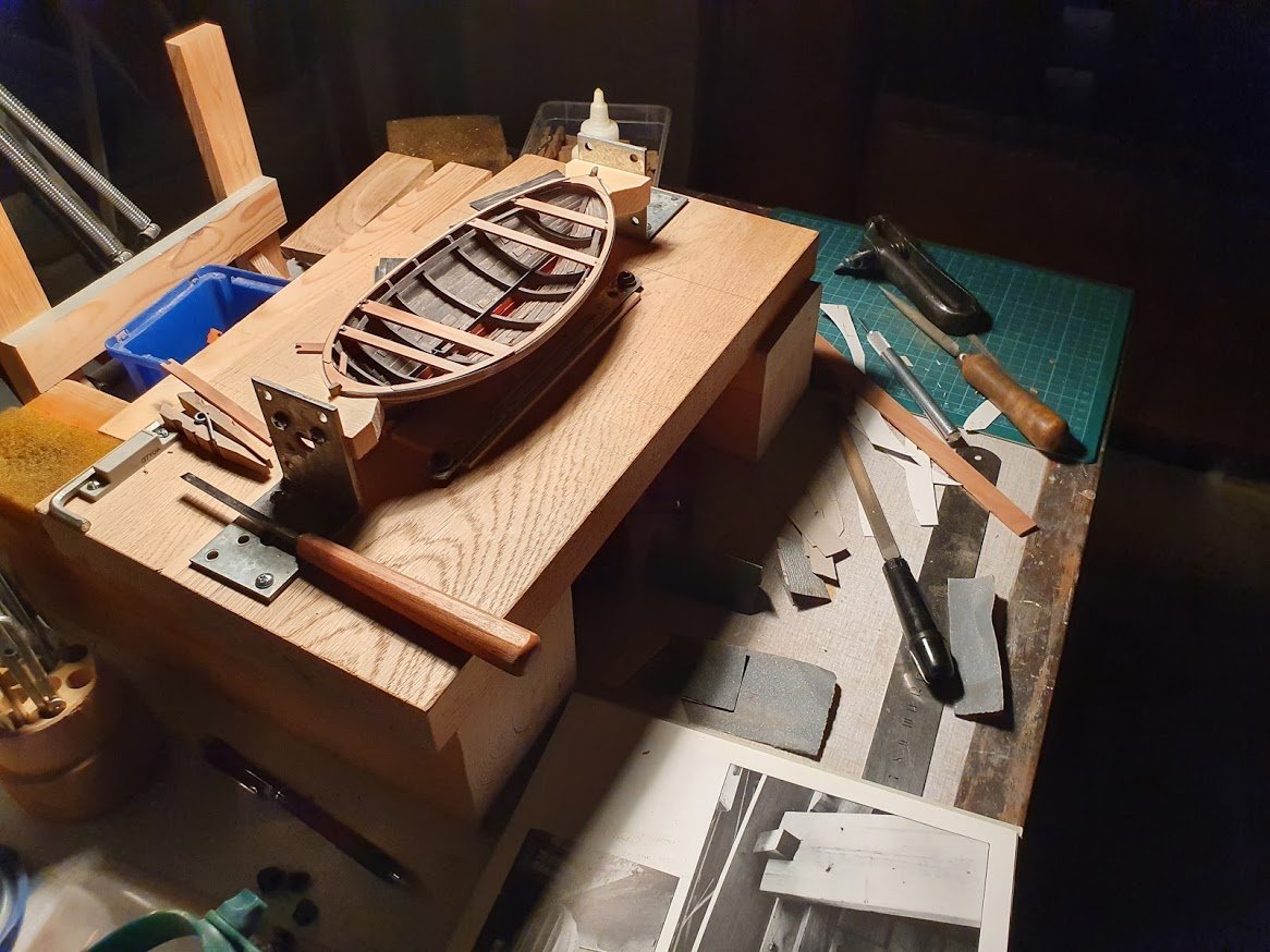
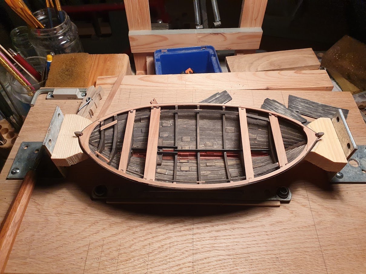
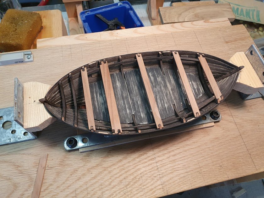
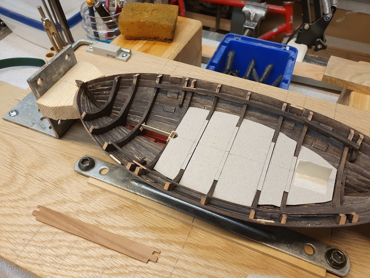
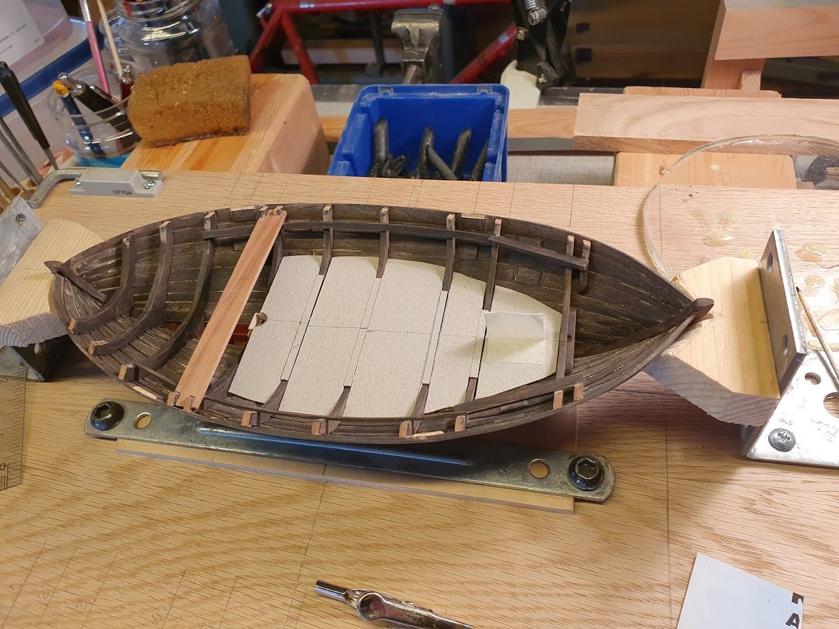
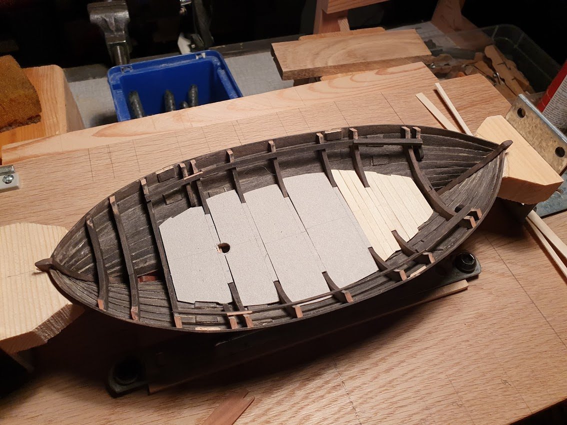
Thank you all for shown interest! @bolin - you are welcome! Steel with pride, as we say on our office 😉 @Mark Pearse @wefalck - yes, I think that the pattern and traditions of building coastal boats slowly spread from area to area. Adaptations were done to suite specific needs of course. Carry more cargo, sail faster, manage different sea states, the list goes on. Here is another small update. All floor boards are done. I didn't get the colour right so some more finishing is needed. All but one thwarts are cut and positioned. Two of them will be removable and the rest will be pinned in place. The removable ones are the narrow one in the middle and then also the foremost one, which I haven't done yet. For every thwart I cut a small recess in the stringer to have them lay down more naturally. For ballast I just went out in the street and wiped up some of the gravel they spread here in wintertime. Some are left natural and the others painted with Paynes gray. The real boat had some 650 kg of ballast. In 1:30 that is almost 90 grams. If I use these "rocks" there is no way I can fit 90 grams of ballast under the floor boards 😄 Next up will be the last thwart and then the covering board along with a couple hefty stem and stern hooks. More of that another time.
-
😄 that table with the dishes still on it made me smile! Lovely detailing!
-
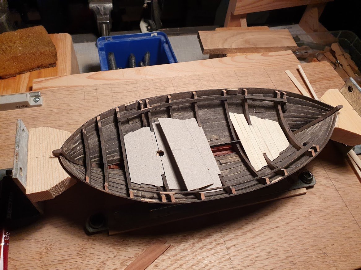
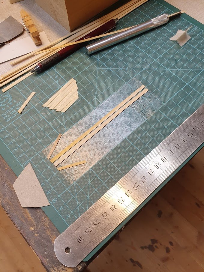
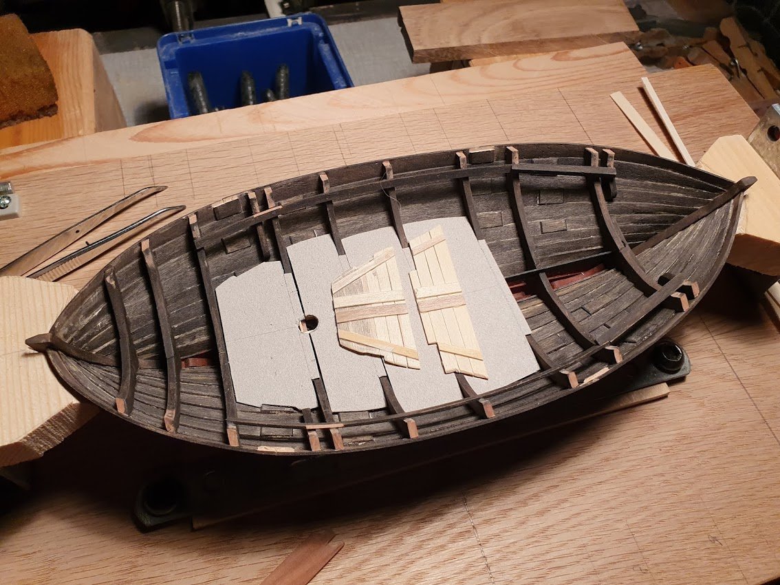
Enough progress for another update I think. So, floor boards it is. First fiddling about with card templates to get a close fit. Also marking the center line on each template because I thought it might be useful (which it proved to be). First a picture with the main thwart though. Also can be seen the "catch" for the mast when raising the same. Templates with a reasonable fit. The butt blocks do interfere with the under side on several positions. Then a short board to support the forward most board. Two aft most boards done. There are no directions in the book about these floors. Only that they rest on that for-aft board in the middle. Therefore I concluded that planks would be athwarthships. Might be wrong, but who knows? If I ever get to see the real boat I will know. This is the supporting pieces. Square and fair. A piece of double adhesive tape on the cutting mat made easy position of everything. One has to wait for the glue to harden before one tries to pry the board away from the tape. Aske me how I know 😄 That's all for now. Thanks for likes and comments, much appreciated!
- 240 replies
-
- 13
-
-
Valuable information for anyone building this kit, I'd say. It's also a slippery slope when you start to investigate and search for authentic information about a ship... all of a sudden you realize all the short comings of kits 😉 However, it's a learning experience and best off will be a balance between kit supplied and own enhancements. (unless you go over to the dark side of scratch builds that is. Then nothing is stopping you and the abyss is deep... 😄 ). Planking a hull IS difficult and there are numerous accounts of how-tos and tutorials here on MSW. Don't rush and you will do just fine! Keep it up!
-
You really upped your pace as of late! Nice progress, crisp and clean as per your usual standards. Keep it up!

