


keelhauled
-
Posts
788 -
Joined
-
Last visited
Content Type
Profiles
Forums
Gallery
Events
Posts posted by keelhauled
-
-
Beautiful work!! Nice detail!
Just a comment on the double O wood versions of the brass sheet. I was intending on purchasing them and kept putting it off until a couple of years back. Unfortunately, by that time they no longer made them. I called double o and they didn't even know what I was talking about. I tried again months later and that person knew what I was talking about and said that they hadn't offered it for some time and no longer offered wood products. Such a shame.
-
Looks good! paint and mount that windlass!
- mtaylor, popeye the sailor, GLakie and 2 others
-
 5
5
-
Hi Nenad,
Yep, they removed the buckets in front of the entrance when she got her new entrance.
Great work on the forecastle!
I just mounted the lower aft dead eyes. I have to admit that I used my "Captain's prerogative" and mounted them slightly higher than they are in reality. I thought that they would really be a pain to rig, so I raised them just enough to give me access to the lower hole. I agree about the deck house being in the way. I pretty sure that I'm not going to mount the deck houses until the mast in front of each one is finished being rigged (going to rig bowsprit back in order). I think that it will be hard to belay all of the sail rigging to the side rails across from the deck houses with the deck houses in place.
-
-
Thanks Popeye!
I still have the mizzen dead eyes to install. I discovered that I screwed up and drilled the holes in the deck the same as they are on the rails which leaves no way to secure the eyes. Luckily I can get to the area beneath the poop deck, so I can glue some wood down there to solve the problem. Hopefully.
Marc
-
-
-
-
Thanks for the compliments George. The more I scratch build things the more confident I become to tackle other projects and the less concerned I am about damaging stuff, or ripping it apart and redoing it, like I did with the bow and stern ornamentation. To date, I think the ship's wheel was one of the most challenging projects that I tackled.
Can't wait to see you start your build, George. I appreciate you keeping up with what I'm doing. Even as slow as I am showing progress. Unfortunately, my job keeps me traveling. And when I'm home I'm often busy doing stuff around the house that should have been done while I was one the road. Hopefully, I'll have some relief from travel this winter, If I can get another body hired.
Thanks
marc
- GLakie and thomaslambo
-
2
-
Hi George
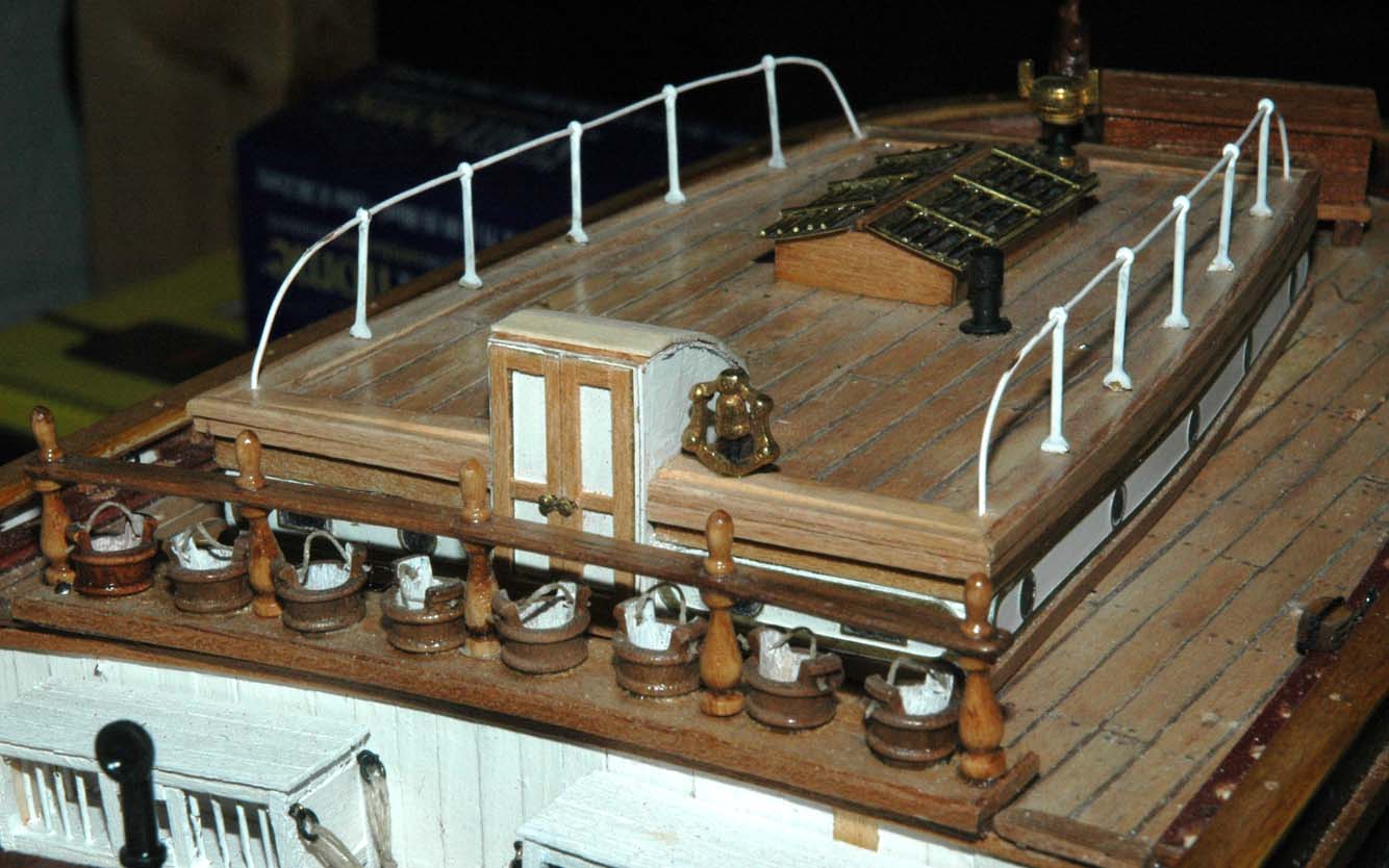
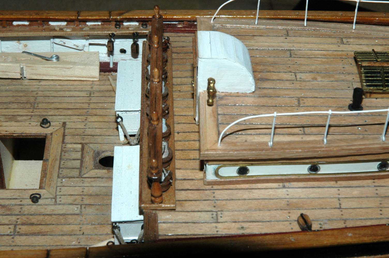
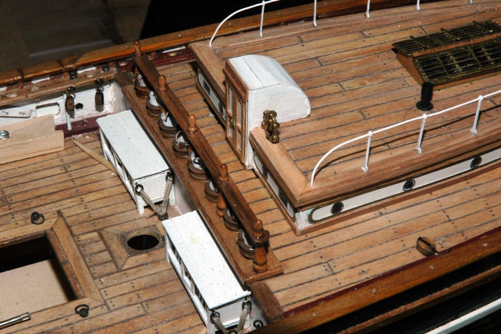
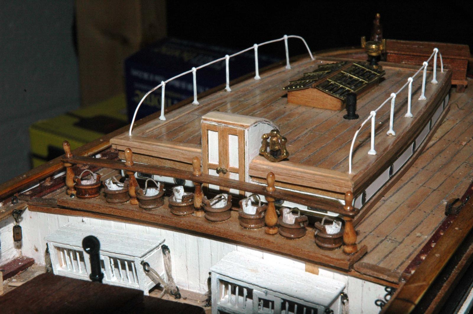
Mantua's model has the ship as she is now. So the stern deck house entrances are completely different. There are three entrances. The incorrect entrance shown in my first photos was scratch built. Just built wrong. The whole deck house with the exception of the compass, bell and windows were built from scratch. I built the skylight from wood and brass. I turned the balusters and buckets and made the rail from scratch. The buckets don't actually taper toward the deck and the tops aren't actually all the same size, but I don't think anyone would notice.
Actually, I stopped using the model plans shortly after planking the hull. I've been using Campbell's plans and filling it in using Longridge's book on the Cutty and Campbell's book on clippers. Also I use as many photos as I can look at. Much of my model is scratch built (except the blocks and dead eyes). It seems the more I build, the less I use of the model.
However, I don't think that the model as built by the directions is bad at all. I just kept finding that I could do better. Although it takes much more time.
Thanks for the feedback
Marc
- gjdale, thomaslambo, GLakie and 2 others
-
5
-
-
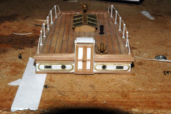
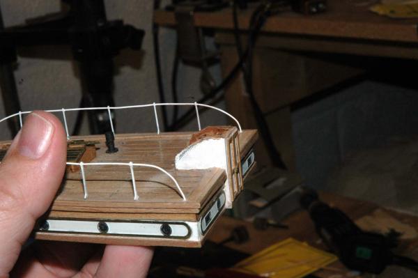
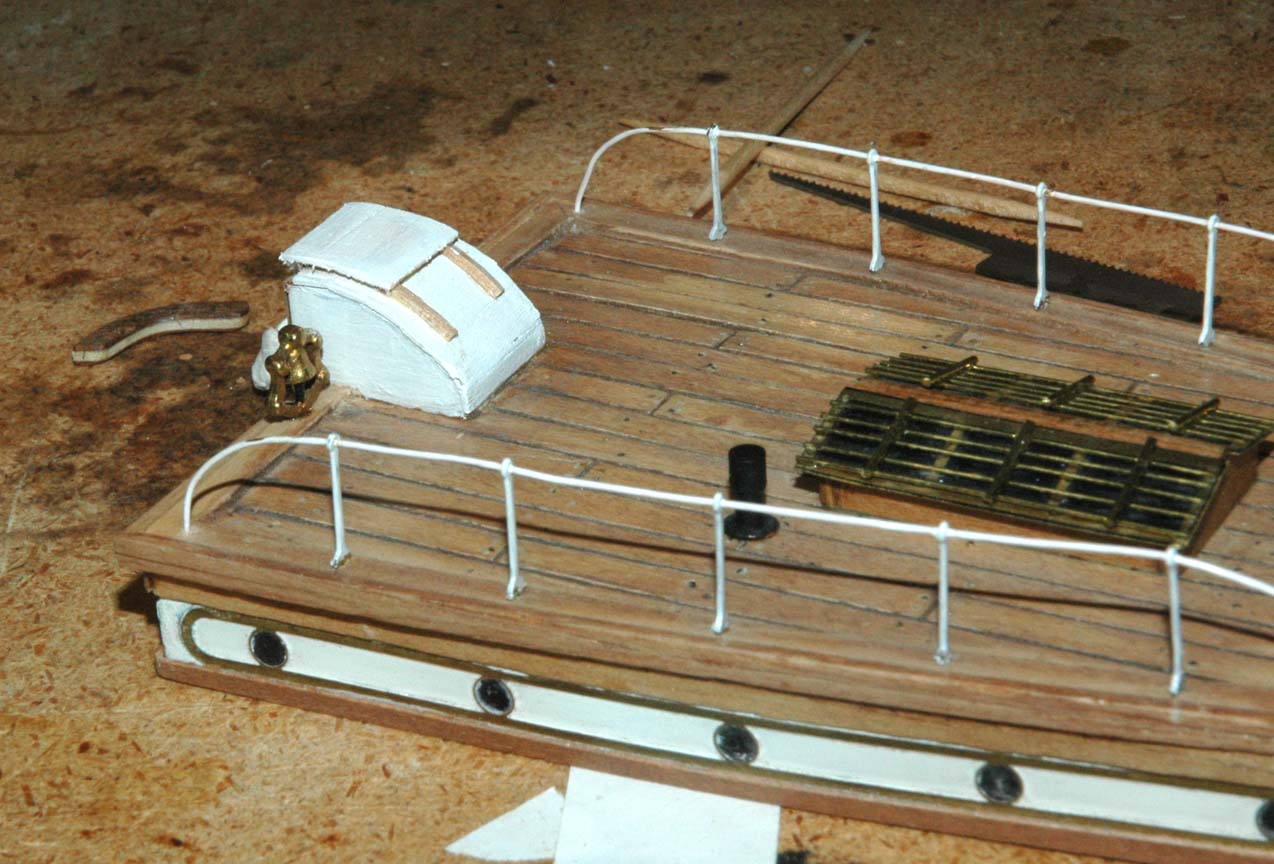
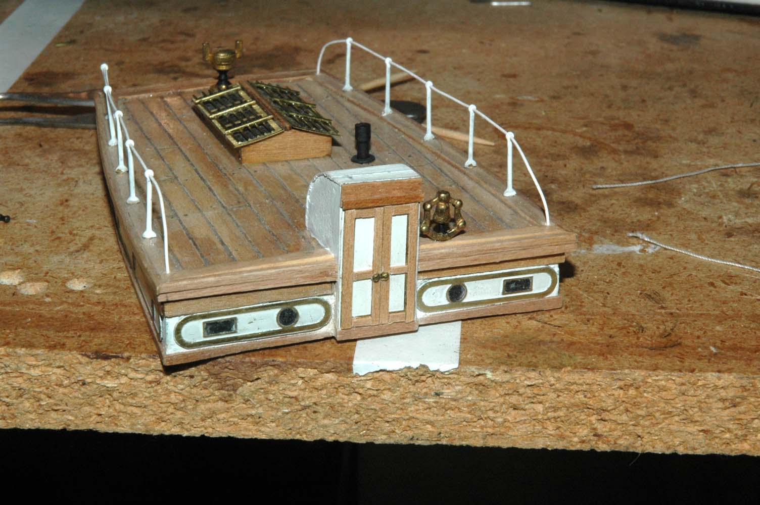
Here is laying down the roof.


And here is the new entrance, complete with booby hatch.


-
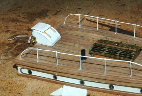
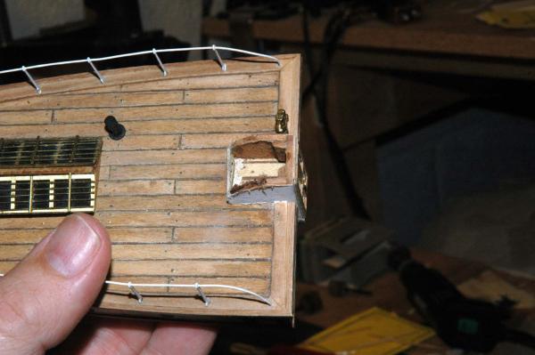
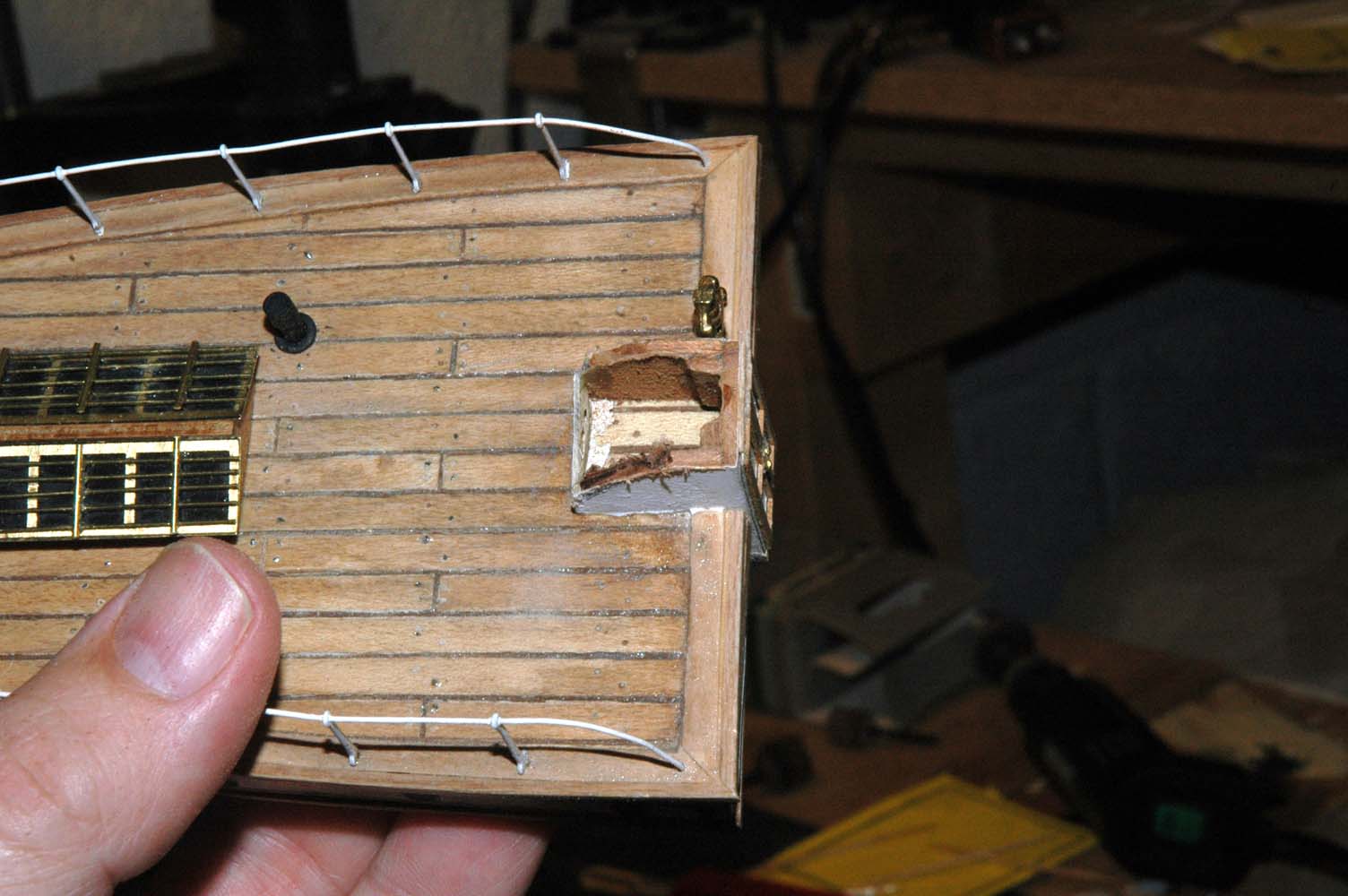
Here is the work on the stern deck house.
The previous entrance was too tall. I had the height the same as what the current height is.
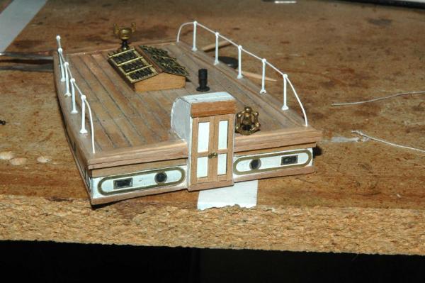

So I gave it a hair cut! I took the measurements off of Campbells plans, made a template and cut the top off with a dremmel cutting disk. I did ware safety glasses.
-
-
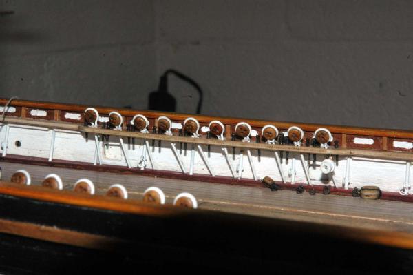
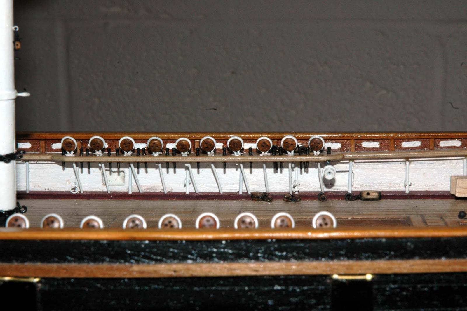
yep George, you're right about the dead-eye orientation. good catch!, the dead-eyes are just loose enough in their brackets to rotate. I was concerned about not getting the exact angle orientation for the holes, so I made sure that I could rotate them if I needed to. When I was placing them, I ended up rotating some of the dead-eyes. In fact most of them are rotated to some degree.
Thanks for the catch, George!
Marc
- GLakie and thomaslambo
-
2
-
Nenad, George, Grant and Thomas,
Thanks for the comments. Having the right tools definitely reduced my frustration and waste and allowed me to make what I needed. It sounds like I might be getting the Byrnes saw for Christmas - Fingers crossed
 .
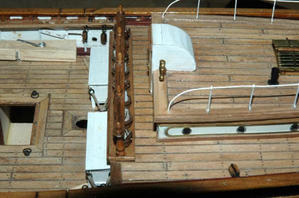
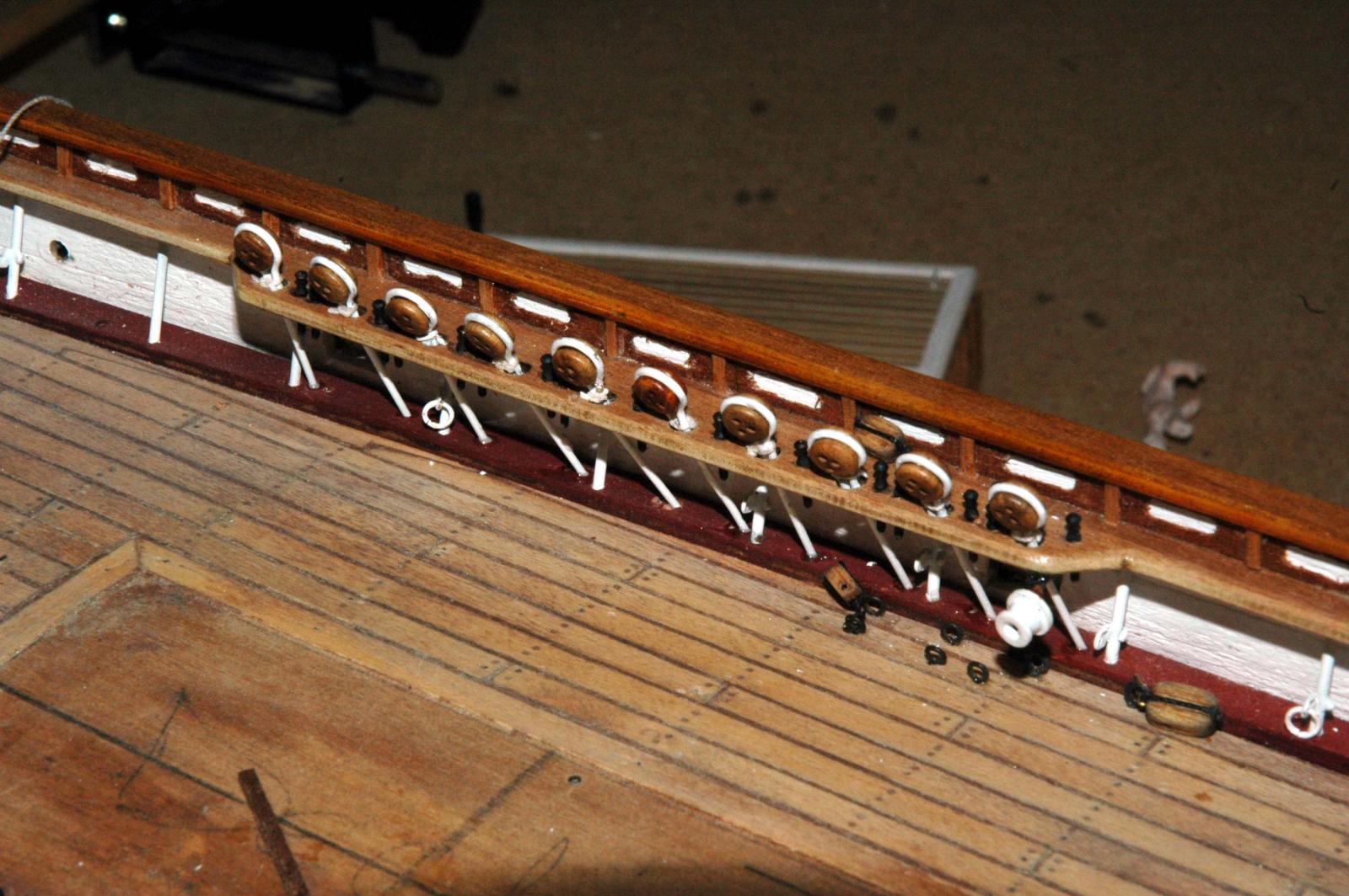
.I was able to get the lower dead eyes mounted for the fore and main masts. Had to re-drill the holes on the deck for most of them. I don't know how I screwed up the angles a few months ago when I drilled the deck holes. This time I checked and rechecked the plans and ran dummy shrouds for each position to check the angle. I finished drilling holes for the belaying pins (wish I had caught that they were missing back before I had mounted the rails).
The fore deadeyes
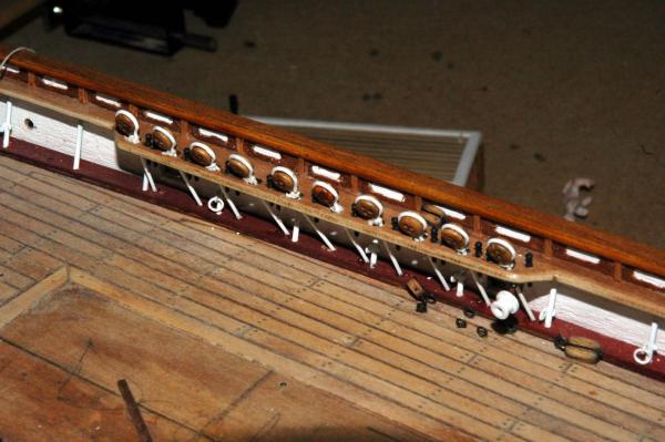
The main deadeyes
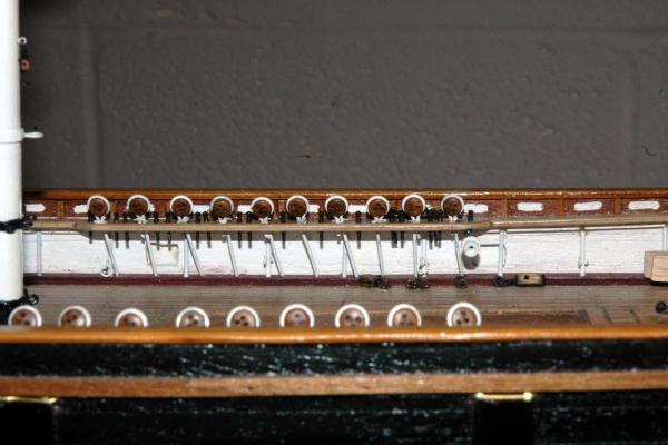
I need to finish the mizzen. Also, I noticed that the entrance to the aft deck house was too tall, so I've started ripping that apart to rebuild. I'll post photos next time.
Thanks
Marc
- Lou van Wijhe, thomaslambo, GLakie and 1 other
-
4
-
-
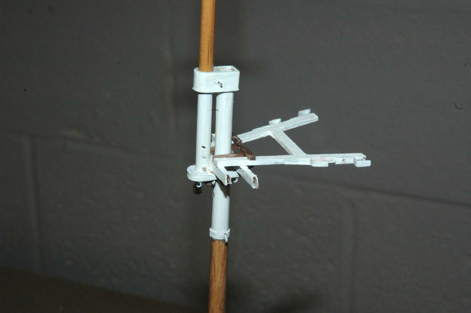
So using my new saw and x-y table I made the fairleads and the bolsters for the masts. I've found that I love ripping wood. Took me a few attempts before the 1/32" x 1/32" came out clean. I think the answer was feeding the wood very slow and not pressing it against the fence.
Had to make the fairleads for the fore mast twice. I couldn't fit enough holes in the length that I had available. I also made sure that the lines would actaully fit through the tiny holes. They do, but I think that I'm at the limit.
fore mast fairleads
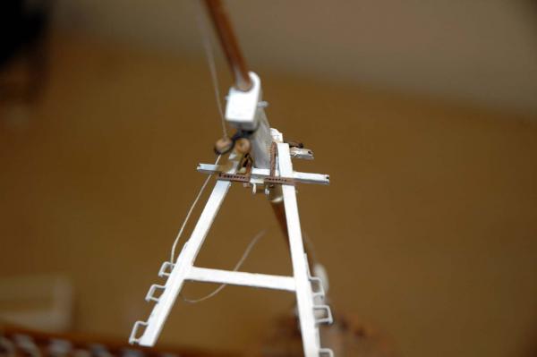
Mizzen mast fairleads

- GLakie, popeye the sailor, tasmanian and 1 other
-
4
-
Thanks George!
Nenad, Thank you for the advice! Sounds like very sound advice. I want to make sure that I keep my fingers and my eyesight! thanks for the examples, I'm very glad no one got hurt.
When I was a teenager I worked for a metal repair shop sanding the items. I forgot to put on my thick leather apron once and the orbital sander bounced and hit my leg. the paper cut right through the canvas apron, my pants and luckily only my skin. Amazing that paper cut through the thick canvas in a split second. I was lucky.
Marc
-
Hi Nenad,
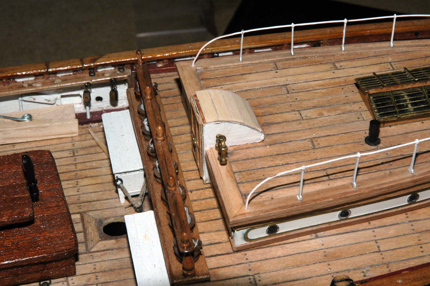
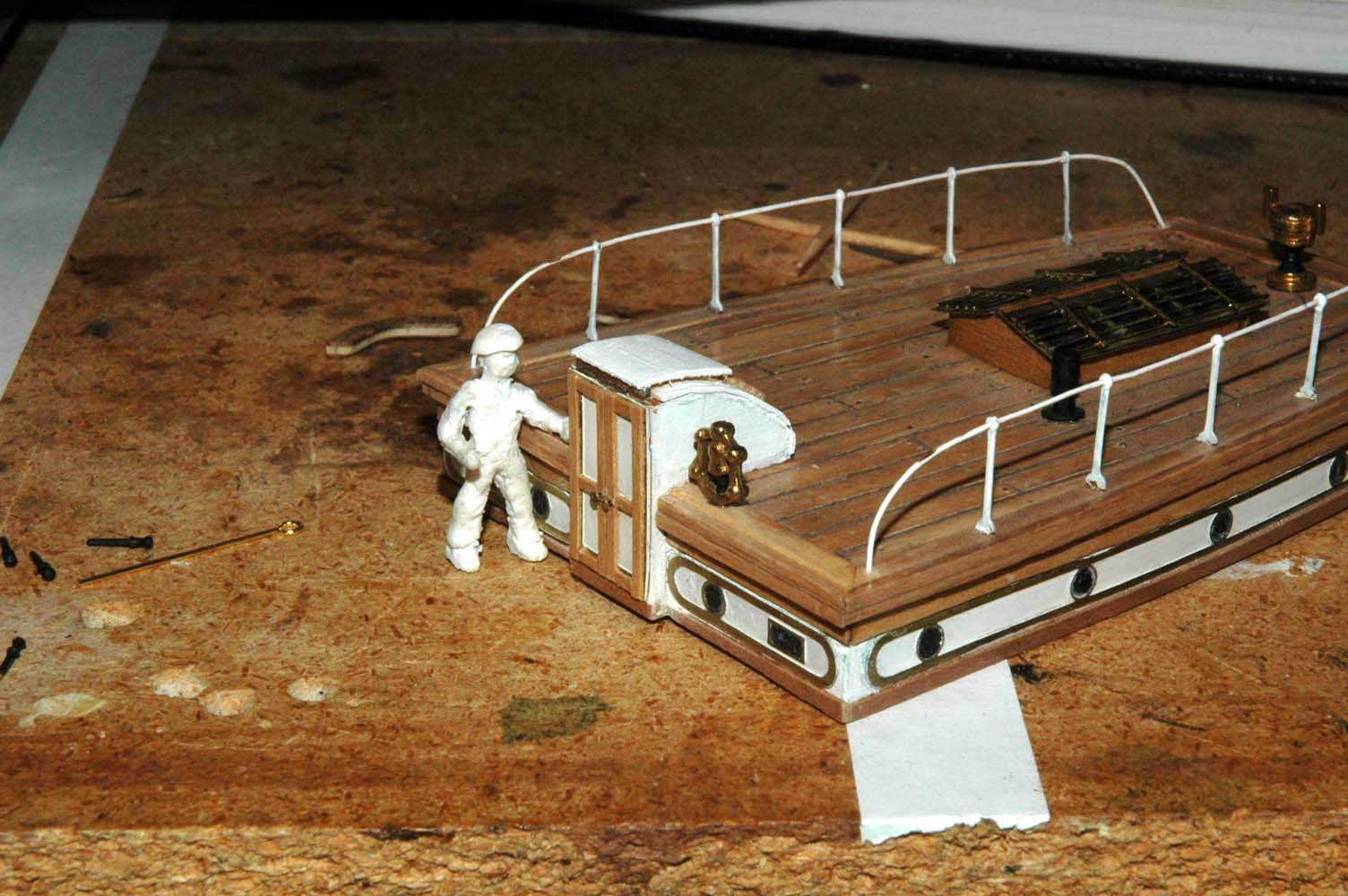
I'm in the process of rebuilding the entrance to the aft deck house. Here are a couple of photos of mine. I thought they might help to illustrate what I was trying to explain.
Excuse the entrance roof I'm still working on it.
Marc


- UpstateNY, Mirabell61, IgorSky and 11 others
-
14
-
Hi everyone,
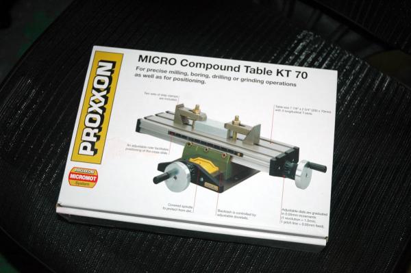
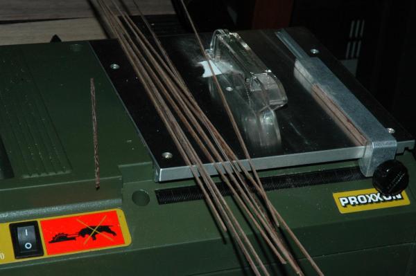
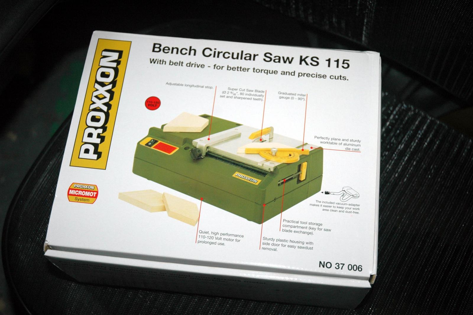
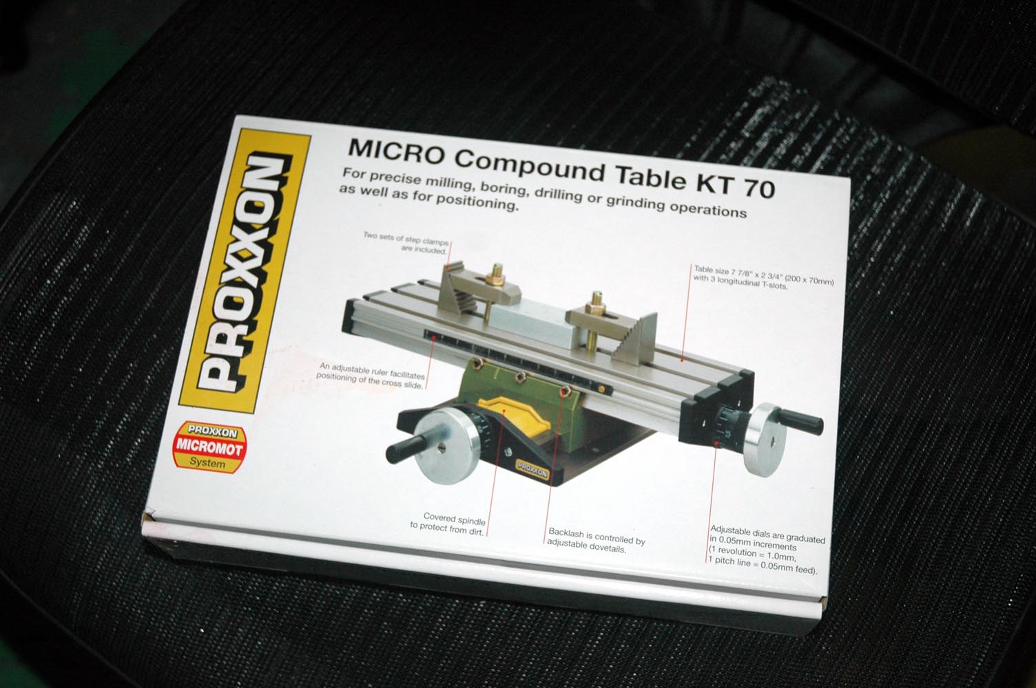
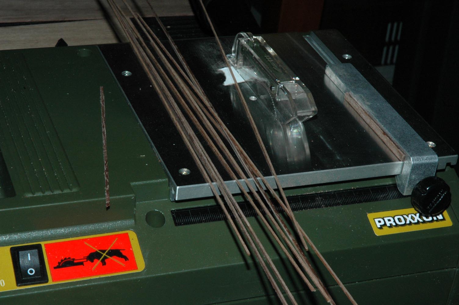
I've been running into issues trying to buy 1/64" x 1/64", 1/32" ,x 1/32" and combos of those size strips. The two sources that I've used in the past no longer make them. I tried cutting those sizes from walnut with an xacto knife and razor blades without much success. too much variation in widths. so I decided to by a table saw. I wanted the Byrnes, but didn't think I could get the support to drop the $600-$800 for the loaded saw. So I bought the Proxxon Saw. Also after drilling all of the holes for the belaying pins in straight rows, I decided it was time to get an x-y table. I know that I'll be making fairleads with holes somewhere ranging from #60 to #75 holes (not sure what size yet) and I didn't think that I could hand drill the holes close enough and consistently enough.
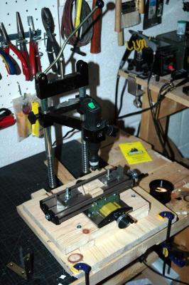
I received two Proxxon tools: an table saw and an x-y table.

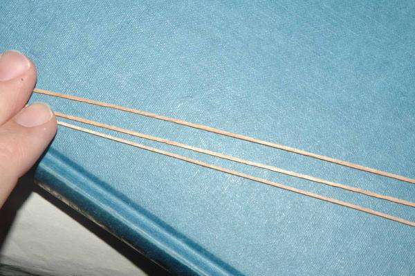
I ripped a stack of 1/32"x1/32" and 1/32x1/16 walnut strips. worked great with the fine tooth saw.
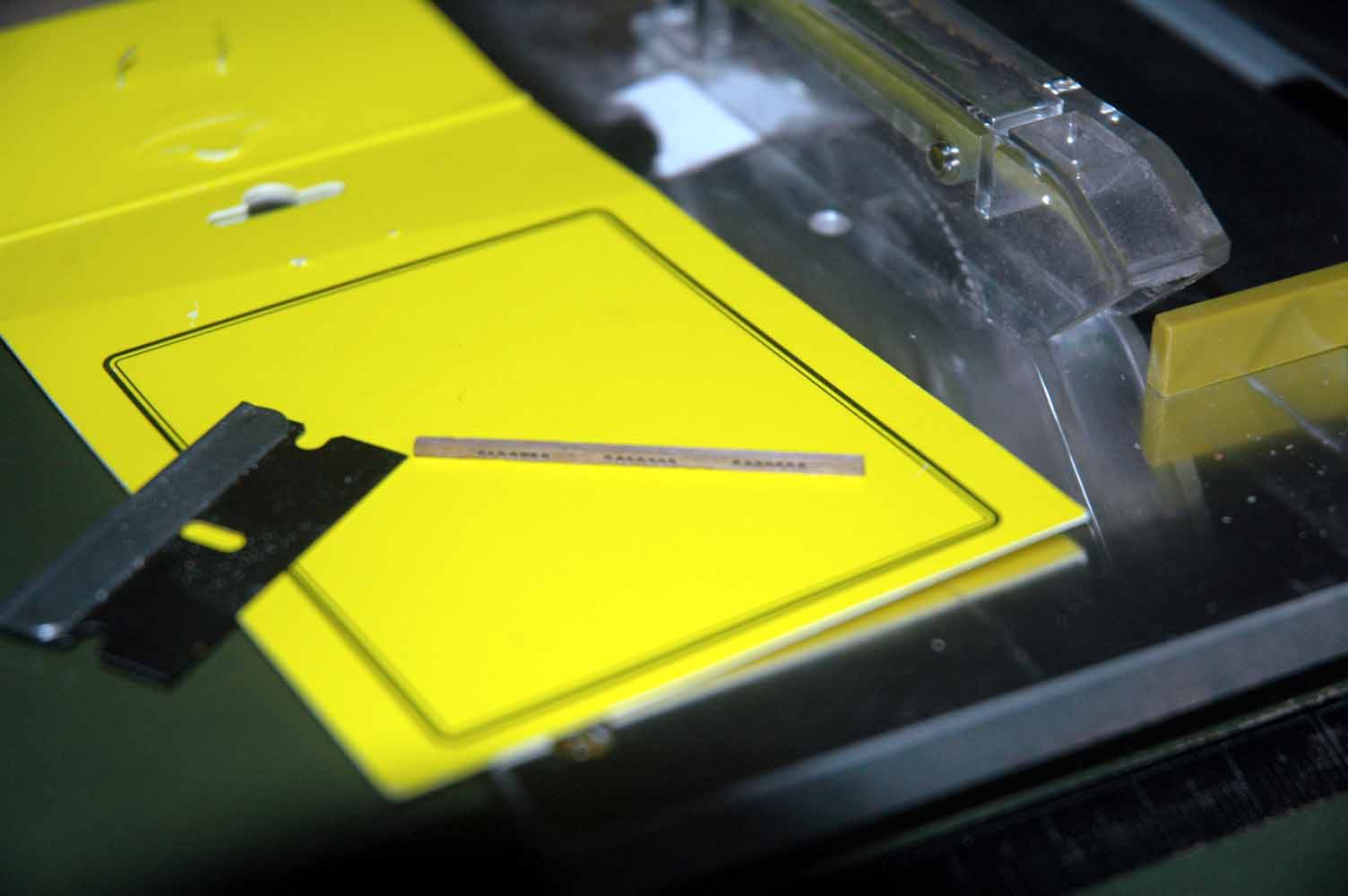
I ended up creating a stop, mainly because I was worried about getting the fence too close to the blade.
I don't have a nice drill, just an old minicraft drill press and the x-y table didn't bolt into any of the holes. Since I wanted to be able to easily remove the x-y table I created a wood sled that the drill press slides into. I was able to get it to where the drill press slides in and out of the x-y table easily and index drill sizes 60-75 lined back up to holes previously drilled across 6 inches. The alignment held in the extreme x and y directions in those same drill size ranges. good enough for what I need.
Here are holes drilled into a 1/32"x1/32 walnut strip.

Drilling test holes for the fairleads . The holes are too large - I won't be able to fit enough holes in for the number of lines. So I'll have to go down probably 5 sizes. The good thing is that with this large of a hole it shows that the x-y table is aligned well. The slight variation in up and down position is becasue of the grain. I tried it with other woods and they were dead-on straight.
Notice how small the little 2 inch blade is compared to the razor blade


Marc
-
Looking great! each new grating is better than the last!
Originally the doors didn't extend past the aft deck house. So the deck between the house and the rail was essentially the same across the entire front of the deck house just as in Campbell's plans. the rail was continuous and the fire buckets were consistent across.
You are correct about the picture of the Queen. When they changed the entrance, they extended it right up to the rail and cut off the lower platform that held the buckets in front of the entrance. The shape of the intersection between sections of the rail is called a scarph joint. It would be a nice detail to add. I wished that I had done these types of joints instead of the angled joints that I did at the time. Live and learn. I'll do it on the Victory when I finally get to her.
Enjoy your vacation!!
-
What can one say that hasn't been said before? Amazing, beautiful,.... It's all true.
Not only the quality, but the build speed with the depth of detail of all of your work is incredible. And you post it all! Do you sleep?
Thanks for giving me hours and hours of joy!
Marc
-
thanks for the tutorial. Very informative!


Cutty Sark by NenadM
in - Build logs for subjects built 1851 - 1900
Posted · Edited by keelhauled
Nenad,
your dead eyes look great.
However, if you decide that you don't feel like making all of them and/or the 300- 400 blocks I know a source in europe.
I've been working with Radek Beseda on developing sails for the Cutty (awesome sails. I just received the final set and will post photos this week).
Anyway, Radek offers C&C blocks. Beautiful work and he really cares about providing good parts. You can tell him that I sent you.
www.radekshipmodels.cz