
HOLIDAY DONATION DRIVE - SUPPORT MSW - DO YOUR PART TO KEEP THIS GREAT FORUM GOING! (Only 20 donations so far - C'mon guys!)
×


popeye the sailor
-
Posts
16,007 -
Joined
-
Last visited
Content Type
Profiles
Forums
Gallery
Events
Everything posted by popeye the sailor
-
 you'd need to figure the scale.......the kit is 1:426. I've been using 1:350 scale PE.......the hood set I bought. thanks Javlin.......I've done it with regular thread in the past.......always hated the fuzzy dust thing. hoping that this super thin wire will be different
 -
bombers are neat........I recently bought a B 25 and a B 17G look'in good so far.
-
nicely done Danny........I see the trucks move as well. you did a super job with this one
-
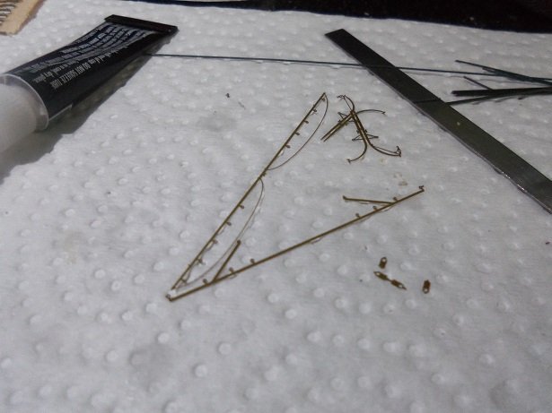
thanks gents I think if I study the pictures @ Battleship Photo Index BB-39 USS ARIZONA more, I might see more to add. what I'm using is some really thin electric cord wire.......I stripped an abundance of it a while ago.....it will look better than thread, I think once it is run, a little bit of primping will straighten it out, although I have it in a bag to keep it from getting all kinked up. thanks for the kind word, and thanks to those who hit the like button would a drowning man refuse a life preserver?.........PM going your way Craig thank you for the offer!
-
yes........there are pictures! looking at the PE, I saw these parts that might be of use..........I'm sure there are more. I made up the larger davits.......these are related to the boat booms, so I will try and do some rigging too. I added the boarding ladders......still need to touch them up. the port side only has one....and as I mentioned, I began to start the rigging. the stern mast is a lot easier than the main mast....there more rigging associated with it. more soon.........thanks for look'in in
- 259 replies
-
- 16
-

-
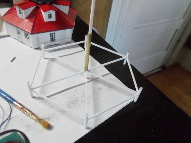
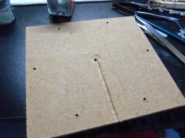
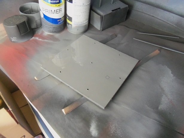
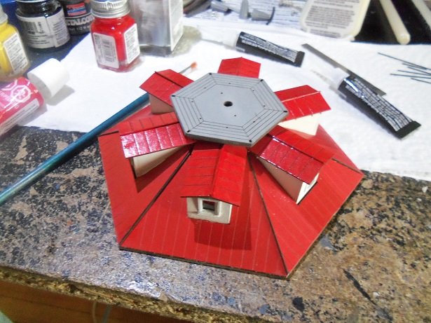
with what I have so far, the screw pile really needs to catch up. for that, I need the main deck, so I can run the other section of braces. on the other hand, if I'm going to paint and run the wiring through the base, the beginnings of the 'pile' needs to come off the base. there was some CA leakage to the base of the posts, as this much was being assembled. there was also instances where joints came apart as I progressed, so I had to re-cement those joints, compounding the problem. this thing may very well be cemented to the base.....could be a challenge to remove whole it actually came off rather well. some of the post were a tight fit, but pushing them from the bottom, little by little.......and equally, worked. only one joint broke in the whole process........it's already repaired. the base, on the other hand, needs a ditch dug under the perma frost . this will be for the wire as it comes out from the center. I have an abundance of the wooden cast off hole plugs from laser cut kits........I will plug off the holes at the bottom, so that when the posts are put back in, they will only go in so far. otherwise I will have to trim the center post. since this will be a display, I decided to simply paint the base gray, like the decks. one thing I did not see, was that the squares for the spacers were 'cut' into the board. this is only one coat of gray primer. here's a shot of the structure as it sits right now
- 97 replies
-
- 15
-
-
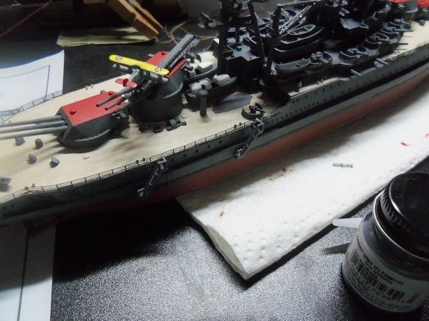
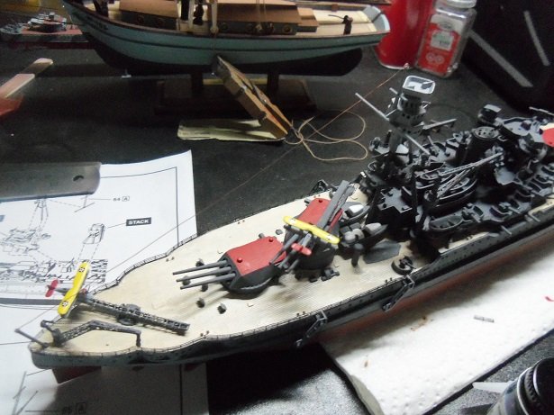
yea......I hear you on the time thing Piet........my vacation was broken here and there still managed to have a good time....and the seafood festival was awesome {ate my weight in clams}! if your like me, I'll play around with something, till I discover that it's turned into a doable project. problem here is.........I have quite a few projects that are like that patience is a virtue my friend.......I'll keep my eyes open for a new project of yours...or the revival of an old one. gives me something to look forward to. I did a little today on the Arizona. at first, I wasn't going to use the boarding ladders........I've changed my mind since. I've also run the first bit of rigging at the stern. to be honest, I haven't done the rigging on too many of these types of ships. my main stumbling block is how to terminate the lines on the deck{s}. do folks drill holes, or just cement them to the walls or deck floor? the hood PE may have some means to help me with this...I hope it does. I will also add the davits Lou.......our talk this past conversation was helpful. I have the large and small ones. sadly now.......I have to go back to work tomorrow......the normalcy is going to kill me. I think I have a picture or two......I'll check
-
checking in to see your progress.........sorry to see your suspending the build. must have taken a lot of work to get the starboard side look'in like that all for the best I imagine. I've never looked into a group build before........it should prove quite interesting hey....what the heck.........tinker in your spare time.........you may be able to save her
-
yes Ken........that is what I thought too I have a couple of alternative types of wire I could use.......I even picked up a roll of wire along the side of the road while walking Gibbs. I had passed by it on a couple of occasions, but this time I stopped to pick it up.......I'm in the habit of picking up trash during our walks {I absolutely hate littering}. it had been run over a few time, but it's still good.......there quite a roll of it......very thin gauge wire. I am using what is supplied in the kit though......it cuts well and is pliable enough to shape any way I need it to. I played around with the Arizona a little today.......with errands to run, there was no sense getting into anything too involved. thanks for look'in in........thanks to all for the likes
-
congratz on the finish of your model! she looks great on display, along with your other ships. truly wonderful job on her....the paint is extraordinary.......such detail
- 146 replies
-
- 1
-
-
- deagostini
- vasa
- (and 1 more)
-
checking on your progress Eric....and boy.....you have done some amazing work! such wonderful detail the second level really looks nice........I have Northeast scale Lumber bookmarked. I found it when I was doing some research on the Ambroid company, which is what they were called back when they made model train kits, along with the scribed wood. Arabia is coming along nicely.....the history is really interesting too great job!
- 599 replies
-
- 3
-
-
- sidewheeler
- arabia
- (and 4 more)
-
one of these days I want to buy a house, so I can join in your misery I miss it like you wouldn't believe! love the chair........sorry.......no alien jokes here. what.....no cup holder?
- 1,208 replies
-
- 2
-
-
- great republic
- clipper
- (and 1 more)
-
Cutty Sark by NenadM
popeye the sailor replied to NenadM's topic in - Build logs for subjects built 1851 - 1900
busy with the small parts......realize though that even in kits, eye bolts and some stuff are out of scale..........but we still use them the chimney could be smaller.....I'm sure your in the process of making a new one. the trials and tribulations of scratch building.......... doing a great job as usual........not sure of the mistakes your trying to cover up.........as I've forgotten already build what makes you happy!- 4,152 replies
-
- 2
-
-
- cutty sark
- tehnodidakta
- (and 1 more)
-
those are delicate posts Mark........very prone to breakage. would it have been a benefit to make them a bit thicker to allow for sanding and faring? great job on the frame so far! this coming from one that is still chained to his scroll saw
-
the black hose does look better although.......the clear hose would have been great if the one could see the presence of air bubbles..........then they would know they need to prime the pump don't mind me........I've dealt too much with problems like that in real life she coming along nicely.......love the engine!
-
I looked up and book marked the site! they have quite a few unique kits.........and I only looked at the first few pages! yup........I didn't see these kits.
-
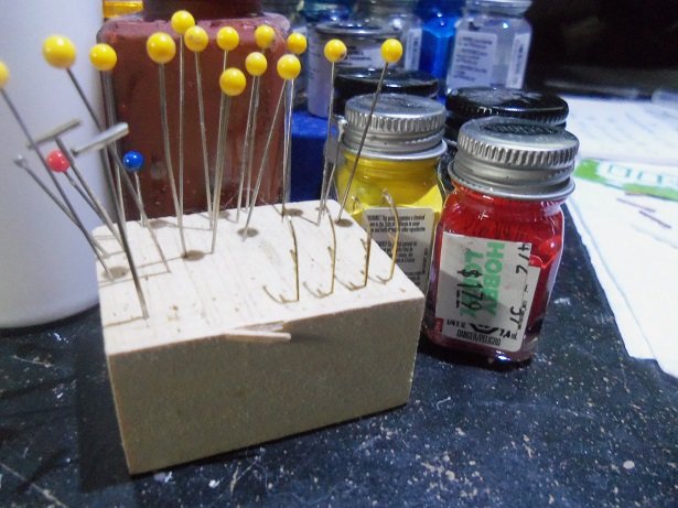
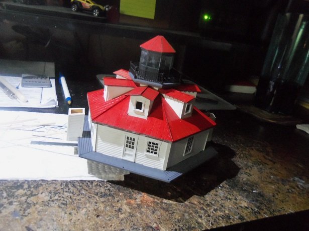
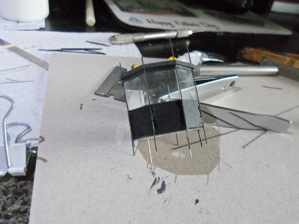
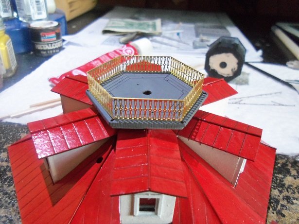
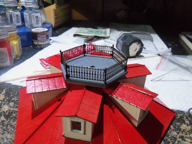
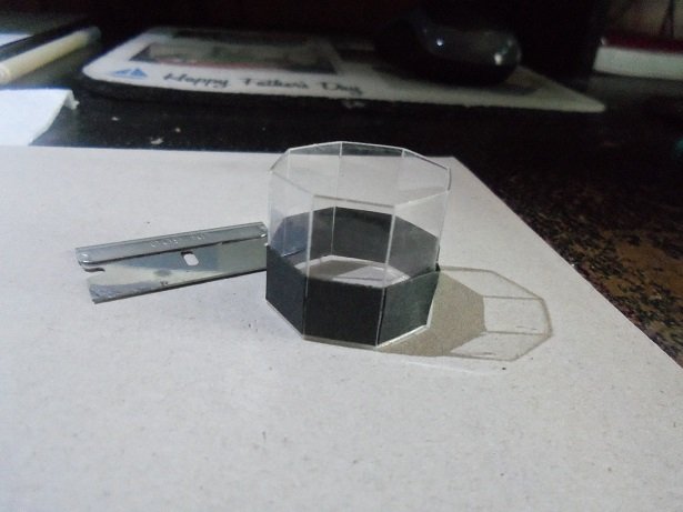
hello Jan you saw that I had glued the beacon glass together........that was short lived once I began mess'in with it. it came apart....that's when I read through the instructions I did have a plan though started in mind, but went with the instructions. sandwiching the two upper parts together, pins were inserted to keep them aligned. the top and bottom were painted gray. the beacon glass was then cemented around the top after it had dried..........the bottom glued in place soon after. for some reason, there was a gap where the two ends met........likely the cause for the formed glass to come apart. taking two thinner rods of metal {I don't believe they are brass...they are painted green}, they were painted gray and run through the holes that encircle the top.......gluing them along the edges of the black bottom. the assembly was then dry fitted onto the beacon deck, using the pins as guides. all of the protruding rods were snipped off, and the black bottom was painted. as for the gap, some 2 mm thin strip was painted gray and cemented into place. in hindsight, I should probably have done it with the one opposite it on the other side, to make it even and symmetrical. I still can, I suppose the plan is to keep it apart for the time being, so I can run the lighting. I ran it today and adjusted the light.......they specify the flash to be around 6 seconds apart........I have it adjusted to be a little quicker. with the lower part dry fitted together, the center tube barely comes though at the beacon deck. the circuit board is to be stuck anywhere outside of the structure via sticky tape that is on the bottom of the board.......just peel off the paper and press into place. I don't think this is going to work for me, since I have incorporated a base. for those who would use this in a layout, they need to drill a hole in the layout floor and run everything under their table. what I would prefer to do, is put the circuit board inside the structure, and run the wires through the bottom of the base.........I will have to create a grove for the wire to run along, and exit the base. I might even be able to run another light for the structure {can't do the dormers.........shucks}. it would have to have direct current, running it before the flasher circuit board. we'll see how things go until then the railing around the beacon was formed.........it still need to have rail posts added. the parts that I thought were the rafters for the dormers, are actually the posts for the railings. the posts were added and the railing assembly was painted flat black. the beacon roof was cemented together, and like the other roofs, need the wire rod treatment and a round ball on top. more on this later on. the pins will also be removed later on and I will glue guide pins where the base and beacon deck meet.
- 97 replies
-
- 17
-
-
these are fun to build.......haven't built one in quite a while though. depending on how long you had them, short run kits like that become rare in a short period of time. is Ace still in business?.......are the kits dated?
-
''''''hmmmmm............that's still a bit traditional. most frigates and war ships have their armament low and within the hull........my plan is to add upper structures, while still maintaining the sailing ship appearance. this is why I chose a clipper hull.......give it a lower draught, and build upward.....the masts will adjusted to allow for space. cool picture.......a defense dept. secret?........the world may never know
-
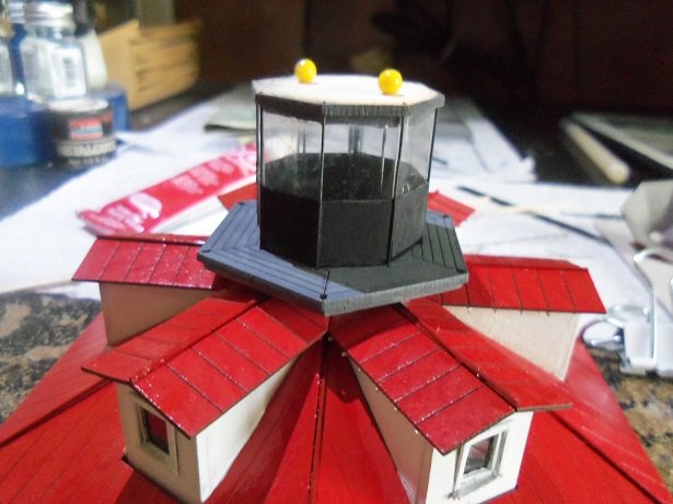
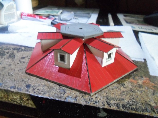
....didn't think of it actually.....even when I was putting the black border on the bottom. of course, I haven't read further ahead in the instructions either. now that I have.........it's not that much of a question anymore. for the beacon assembly, there are three octagon parts.......one for the roof top, one for the top of the beacon, and one for the bottom. all of these parts have alignment holes, which will come in handy assembling it. I've been working on it as we speak...........next update
-
thanks Phil........glad you like it Lou, I see your trying to stay one step ahead of me...........right?!?!?! since you asked..............a while ago, I had this crazy idea to do a what if battle ship, but done in a sailing ship format........dunno......1800's perhaps. now I know there was the Warrior, the Alabama, the Kearsarge.......think of the set up of these vessels, in a more modern way. I know it's a stretch........the sail configuration is going to be a huge dilemma. anyway.......I had traced out the parts for the hull, using the Thermopylae parts panels........did this months ago. I finally got around to cutting them out........assembling the frame..........and faring the frame out. two last bulkheads of the stern and the smaller bulkhead at the bow {the one on the stem}, I have not done yet. I'm not decided of how the bow and stern will look. I want to use some of the Hood PE parts to build up the structures.......I already have the cannons it's still in the planning phase.........I think it will be an interesting endeavor. if it all comes down on me........I have a great start on another clipper ship I never cease to amaze me
-
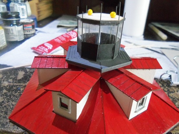
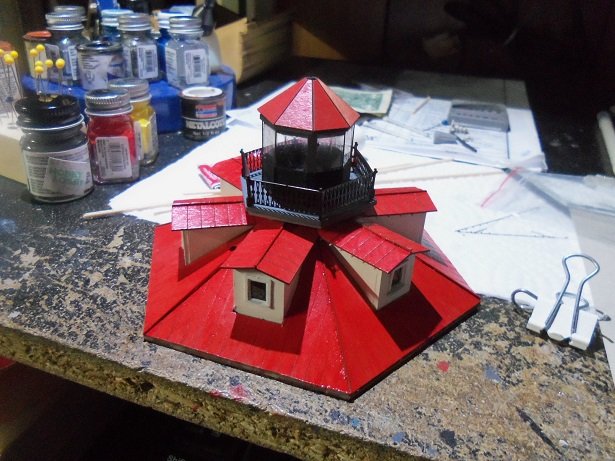
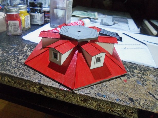
the windows went in flawlessly! the dormer windows however was another story. after cutting the glass and cementing them in place, adding them to the roof was a feat and a half. I ended up breaking a second window in the process and had to fix two of 'em for the price of one. the repairs went well though, although one of them has a speck of 'something' on the glass. it's on the inside.........due to the fragility issue, I'm gonna leave it. think of it as a small white cat sitting in the window ..........cone on...........you know you want to along the crown of the roofs, .030 wire was cemented in place {supplied in the kit} this led to a bit of a mess.........they will be painted red. I'll touch up the roof panels while I'm at it the dormer roofs are done here. the bottoms are done here..... there is edge molding that will encircle the roof assembly.......I'll get to that next. after scoring the black apron around the beacon glass, I bent it along the scored lines that separate the panes. this led to another piece of the puzzle. now I left a thin border around the bottom to eventually cement into the beacon deck. if the beacon glass forms an octagon........how is it going to fit into the beacon deck, which is a hexagon? I submitted that question to the 'ponder department' waiting for an answer to it....................................................................
- 97 replies
-
- 12
-
-
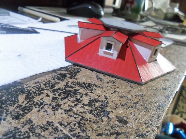
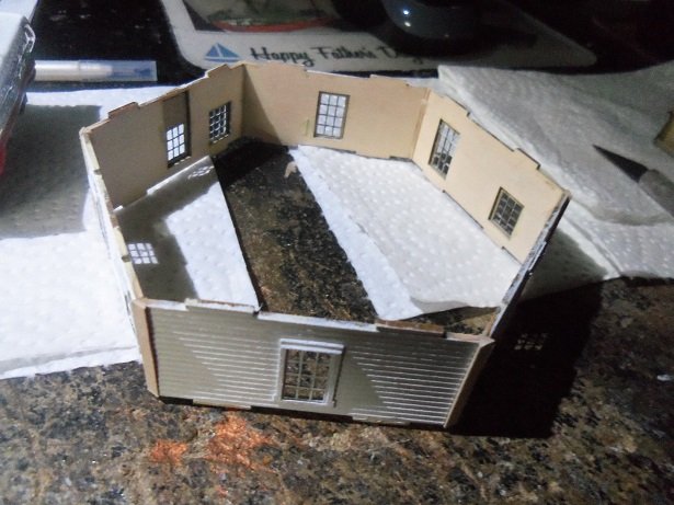
I did snap these two pictures of the window prep........the wall cemented together.........and the two sizes of window glass {cello}. the tops and bottoms of the corner moldings were sanded flush to the walls. I marked the top and bottom decks for proper orientation of the the wall {sandwich}.
- 97 replies
-
- 10
-