HOLIDAY DONATION DRIVE - SUPPORT MSW - DO YOUR PART TO KEEP THIS GREAT FORUM GOING! (Only 51 donations so far out of 49,000 members - C'mon guys!)
×


Thanasis
-
Posts
652 -
Joined
-
Last visited
Content Type
Profiles
Forums
Gallery
Events
Everything posted by Thanasis
-
Making small nails with round head
Thanasis replied to Aleksei Domanov's topic in Metal Work, Soldering and Metal Fittings
You could try by visiting a local repair store in which, a non functional CPU might be given for free, related Fb pages where you can find them also for free or by an exchange and finally from the ebay starting from around 2 euro-dollar. Thx -
Making small nails with round head
Thanasis replied to Aleksei Domanov's topic in Metal Work, Soldering and Metal Fittings
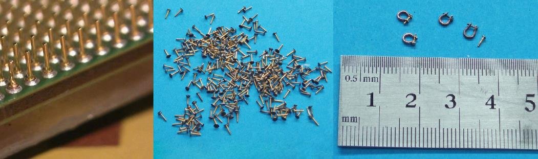
Hi all. I really admire and appreciate whoever scratches everything on his model... As about me, I prefer the shortcuts whenever I can. I have placed it also somewhere...For those who think alike take a look inside of an old pc. Every processor (CPU) can give you many tiny nails with round head. It depends on how sharp eyes you have, to work with them... Thx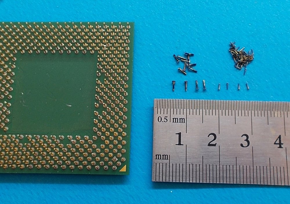
-
Hello. Another source of small nails is an old pc processor... It's surface are covered with pins, which can give you up to 100 "nails" by setting up a small fire in your backyard and take out the last offer of it …. I use these nails as “keys” for my shackles. Just to notice that many of those pins come out with some lead on their head. Just keep them with a tweezers over a lighter's flame… Thanks

-
Hi Kostas. Although we didn't meet each other in that contest, I've been there and I saw your model from close. It is exelent. Congratulation for your prize. Keep on the good work. Thanasis
- 70 replies
-
- 1
-

-
- san francisco ii
- artesania latina
- (and 2 more)
-
Hi Nails. I would be ungrateful if I stayed still silent... I didn't dare to make any comment until now, thinking that it would be like if I was judging you on every step of you built. And I don't have the right since I'm not even close to your level. So, you have built a beautiful model that has been created through an inspiring modeling school for all of us. Congratulations Thx

- 692 replies
-
- 6
-
-
- eagle of algier
- chebec
- (and 2 more)
-
Thank you all for your likes and comments.! Kostas nice to see you still here.. Friendly to all. Thx
-
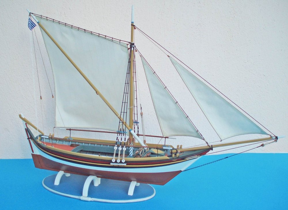
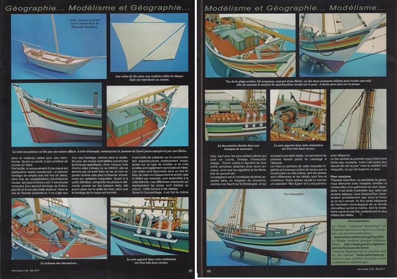
Hello all. You might have noticed my absence but I’m still here… Well, it’s been a long time since a previous presentation work of mine but I’m not notorious for accurate build logs anyway. So I have come to prove myself again … I started the model one year before accepting the challenge to build a model with open hull. I didn't work on it regularly, so that's why the lack of many photos, not that I have in my mind to take photos in other case… I chose to represent a vessel from my place of origin, the Island of Mytilene (Lesbos). It was a small double ended vessel (Tserniki type) which was used for coastal trading. It was usually rigged with a half lateen sail or a sacoleva sail (sprit sail). ...... I observed many photos of that vessel from the archives of 3w.naftotopos.gr and I modified an old plan of that hull type. I built the model following the method plank on bulkheads removing a number of them afterwards from the middle of the hull. I prepared the false frames by soaking proper pieced of wood, bending them and drying them on the surface of the removed bulkheads. ...... I had to paint the inner of the hull before I plank the deck and keep it covered for the rest of the construction. ...... The grapnel anchor was made by using fishing hooks that were set and glued inside a hole in a plastic rod, while the cleats on the mast were made by modifying some fishing swivels… The Shackles were made as is shown there The Belaying pins were made as is shown there The Sails were made as is shown there The cargo was made by chopping some twig pencils. It took me much time to decide about the colors on the model…Painting is always the only stage of my builds that stresses me. Wanting to give a local-origin character in my models, I'm always anxious whether I have chosen the right colors or I have turned it to a clown. ...... Finally the stand was made by a piece of plywood and some wooden rings which were cut in half. I hope my wife won’t notice the missing curtain hoops... See the finished model in gallery. Many thanks
-
I'm not a fan of kit models but I would like to see many more Mediterranean and more humble (less known) sea vessels (not Ancient). Thx
-
Many thanks!
-
Seizing/splicing step by step...one method
Thanasis replied to Chuck's topic in Masting, rigging and sails
I have also used a similar to Chuck's tip. I opened up the rope and passed through only one of the three strands. After applying some ca glue, I cut the two other strands and made some turns around the rope with the first one, covering so the cuts and simulating the seizing. Tserniki vessel of Mykonos Thx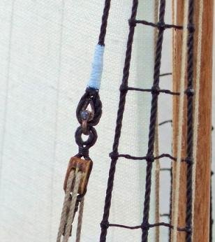
-
Beside wood and time saving, a full length plank can give you smoothly the curving lines of a hull, rather than a row of small planking parts. But that depends on everyothers will. Thx
-
Hi. Depending on the length of the dowel (upper mast) see whether you can cut it in two pieces. Then open holes, at both pieces and place a metal thin rod (unbendable) that will connect them from within. Put the metal rod at one piece of wood at a time and after you have applied some ca glue on its surface. Finishing you can cover the cut by a hoop, as a part of the rigging. That's I would try before I turn to make a new one. Thx
-
I will agree with wefalck up to a point. According to Gr. book "About the rigging of the ship" (Περί εξαρτισμού των πλοίων) of 1919 at page 96, the hem of a sail is not being folded (back) and sewed alone but there are additional fabric strips, that are being placed at the front of the sail and then are sewed together. Also in the Gr. book "Terms of sail ships" (Ονοματολόγιο ιστιοφόρων) of 1890 at page 112, there is the French term "les doublages" that is referring to fabric strips that are being sewed at the sides of a sail to give reinforcement. It doesn’t say on which side (back or in front) so I can only guess what that "doubla" means. So at least me, I can accept hem on both sides of a sail. If someone can read Greek, I can place photos of those pages. Thx
-
Mike, I use that cotton fabric that is being used for bed sheets which first I have ironed it well. I use a sharp razor, I press the fabric with a metal ruler and I make the cuts over a piece of cardboard. Thx
-
Hi Mike. Yes this is a part of my lazy technique, when I make sails for my models. Take a look there: Aegean Tserniki vessel Thx
-
I don't know what kind of grommets were being used on the sails of Arrow. To my knowledge the grommets as sewn metal eyelet (not as hammered grommets) were known at that period. Certainly wefalck's method could imitate also the sewn ones. Thx
-
Hi Mike. Make the holes on the sail-s. Then insert the point of a pencil in every hole and give it some twists, marking this way the perimeter of each hole. Make the same in the other side and the result will give the illusion of a grommet. After the marking on the holes, you can reinforce them by inserting a toothpick which you have soaked it a bit with ca glue and give it again some twists. That's what I do. Thx
-
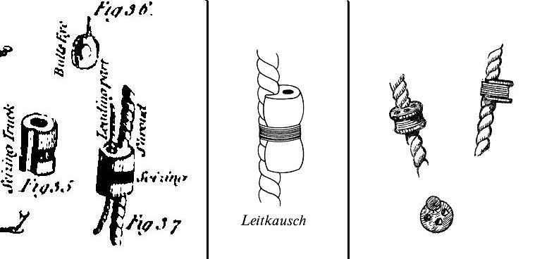
From my library. Thx
-
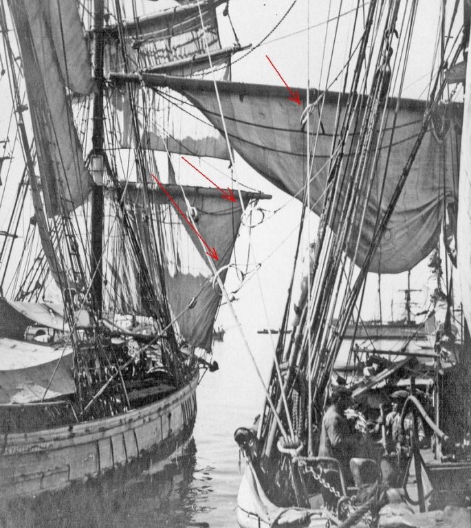
Hi all, Could be also considered these rigging items as "fairleads" or is something else. I haven't seen them before. Thx
-
Hi Chazz. Take a look at the links http://modelshipworld.com/index.php/topic/8936-zip-ties-yes-or-no-for-seizings/ http://modelshipworld.com/index.php/topic/1255-question-on-false-seizing-zip-seizing/ (Sorry, but if you have problem with the second link , I don't know why it doesn't work properly...works perfect through the first link though) Thx Thanasis
-
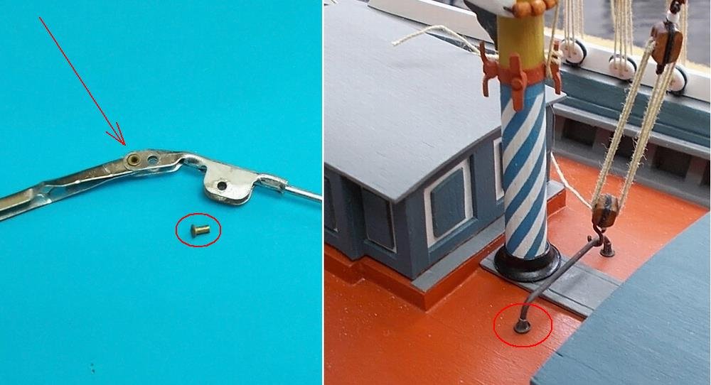
Hi Derek. I had also bought one pack of those to find out that they might do what are promising only when the planks are in low thickness and with a gently tension of the screw. Otherwise, as it happened for me, that small plate tends to distorting, pressing only the closer to screw side of the plank... Now, I use those plates in a combination with board pins (instead of screws), which because of the wider base, they prevent the plate to be deformed. As about the pre-drilling on the bulkheads, a smaller in diameter than the screw drilling, usually helps. Thx
-
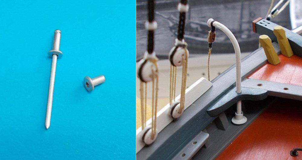
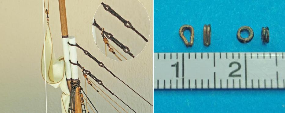
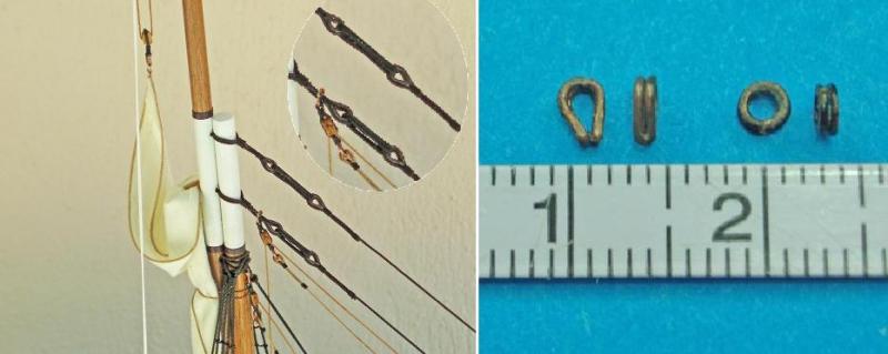
Hi. John here's my tip, fast and cheap. Take a piece of relatively soft wire at a thickness close to the side of the thimble you want to create. By the "side" I mean the part of the thimble that it will stay uncovered when the thread (rope) is placed. Fold the wire in two pieces and make a loop around a rod in a proper - required diameter. Cut the rest of the wire and apply some ca glue between the formed loops. Then with a fine file, make flat the curved edges at the side and you've have your thimble... Thx
-
A Greek proverb says: "When you hear of many cherries, hold a small basket”... The ship models can be seen also there: http://greekshipmodels.com/en/home/ Thx