


gil middleton
-
Posts
308 -
Joined
-
Last visited
Content Type
Profiles
Forums
Gallery
Events
Posts posted by gil middleton
-
-
Thanks Lawrence and Mark for the heads up. Who ever thought we'd need computers in building model ships? But then I remember modeling before MSW. Each of us working in our venue, our resources limited to a few friends and a collection of books and our horizons bound by our travels to ships and museums. And suddenly with MSW, passionate modelers from around the globe offer ideas on a daily basis and friendships kindle. OK! Lawrence and Mark, I'll work on my computer skills.
Grant, Glad it helped, but with your skills, I'd bet you'll come up with something better.
Cheers, Gil
-
Grant and I have been discussing shroud cleats through private messaging on MSW. In order to continue the dialog, I need to post photos which on my version of Internet Explorer, doesn't work on MSW. Hence, to Firefox and my log.
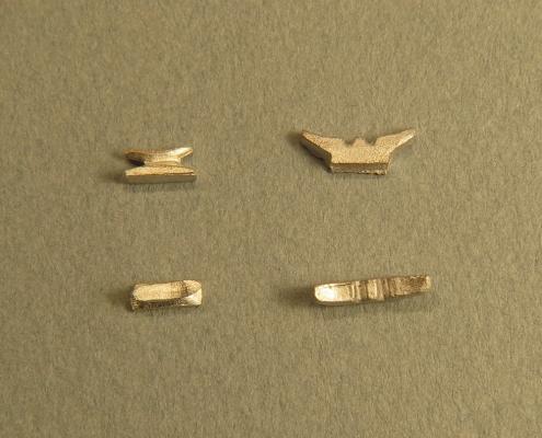
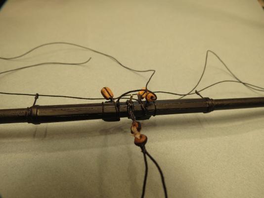
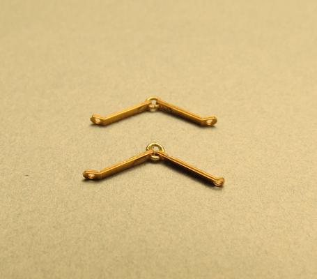
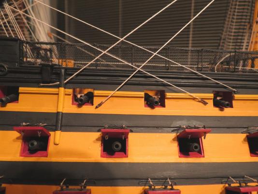
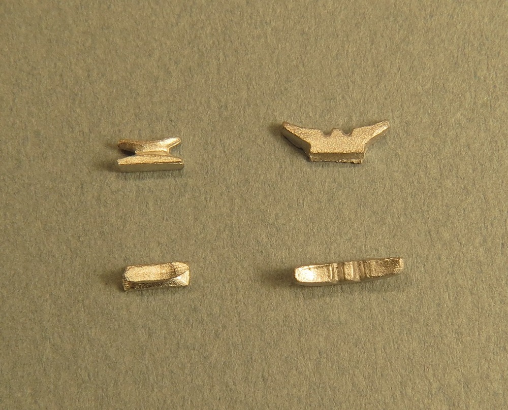
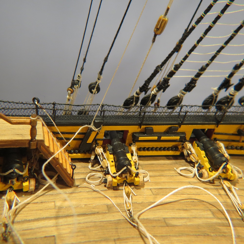
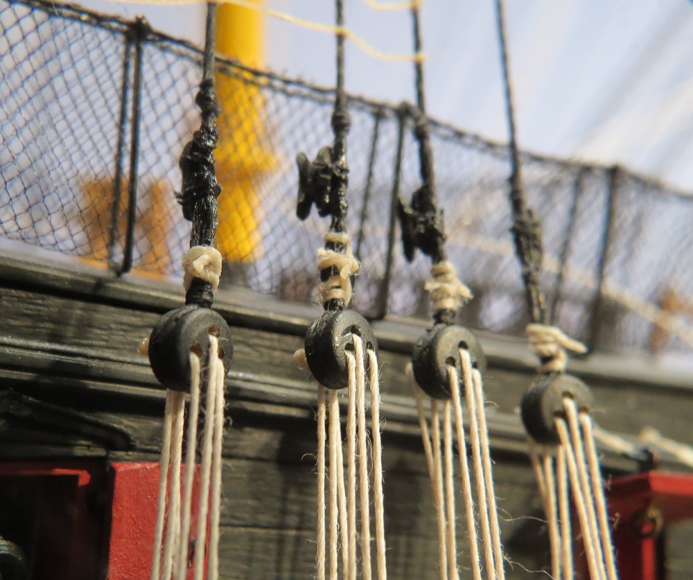
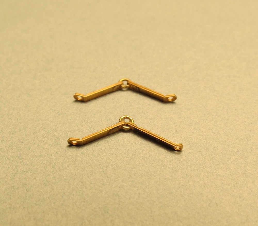
I wasn't satisfied with the supplied shroud cleats. They appeared too large of scale and required lashing over the center of the cleat. Longridge and McGowen (McKay's drawings) showed cleats lashed on both ends of the cleat. Accordingly, I went with Model Shipway's 5 mm. cleat (not currently in stock). The following photo shows on the left Model Shipway's 5 mm. cleats and on the right the JoTica supplied cleats
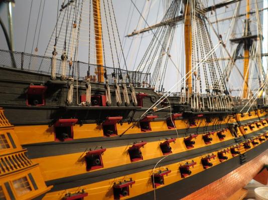
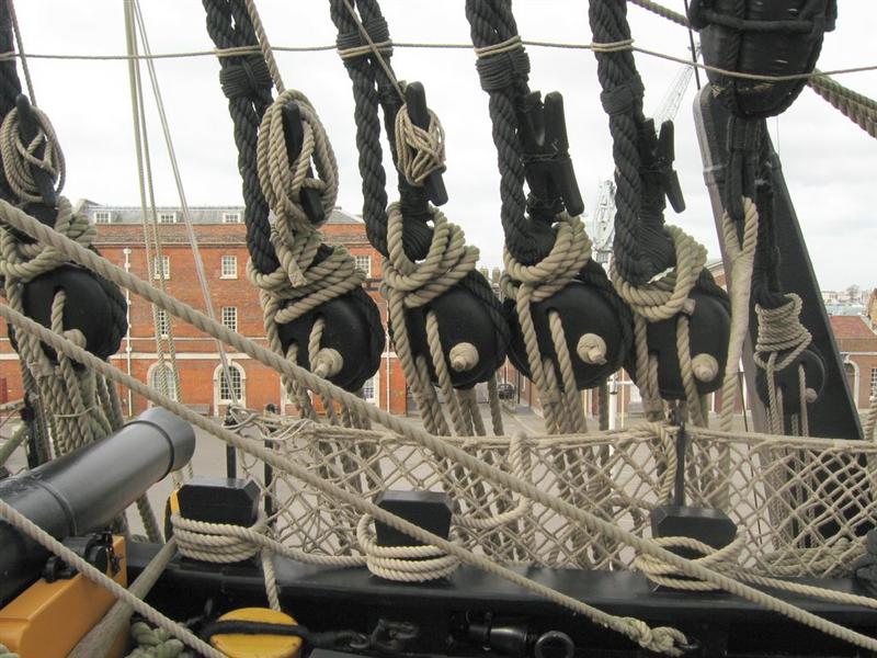
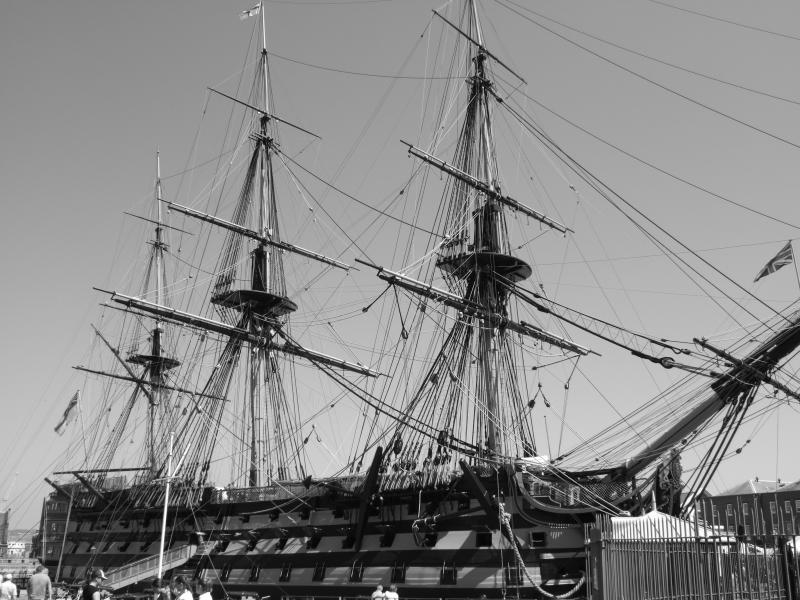
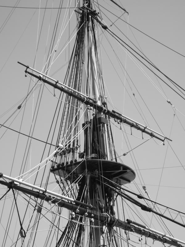
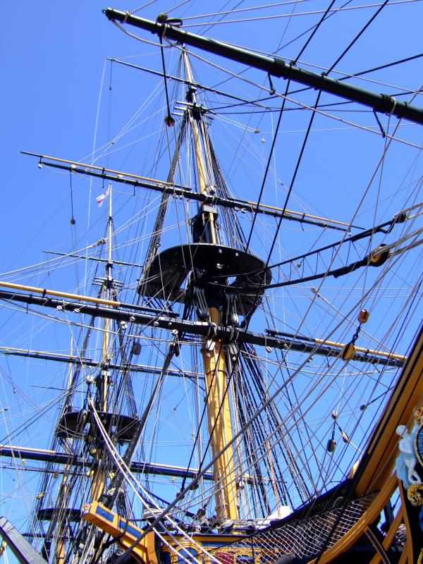
Shroud cleats on the real ship

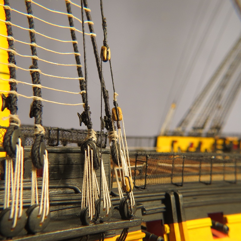
Shroud cleats on the model


The mizzen shroud cleats required filing down the width in order to fit the smaller shroud lines.

With macro photography, they look like they were made by a modeller with only thumbs, however, in normal viewing they look rather good. Cheers, Gil
- Kevin, fnkershner, DBorgens and 11 others
-
 14
14
-
Gary, Those early in the "Victory" build will appreciate your suggestion on drilling for the dummy gun barrels. For some of us, it's too late. Good luck getting your log started.
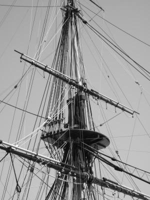
Rich, I envy your location in Portsmouth. I visited HMS Victory perhaps twenty years ago and have hundreds of photographs of the ship, but still find many details where I'd love to have another look. However, you said that the masts were down, which wouldn't be of much help at this stage.
Cheers, Gil
-
Grant, I can't leave your log without missing something. Just had the second cataract done and in those few days, your ship went to sea, brought down the mast in a storm and has undergone a refit. Great recovery by the way. I probably would have taken a month off. And on to new ideas, raising the bar for the rest of us. Gil
-
Thanks Gary. I also drilled the holes too high and after testing, redid them. Kevin, your memory is probably better than mine, however, I'd suggest Gary do the drilling at this stage. The gun port lining is rather fragile and once the planking and decking is in place, the drilling debris becomes part of the model.
Grant, I'm not sure I have the patience to follow the one step forward, two steps back routine, but your results speak for themselves.
Thanks Bug. Your post introduced me to your Santa Maria. I enjoyed perusing your log with the wonderful details, a host of good ideas and a history lesson as well.
Are we having fun yet? Cheers, Gil
-
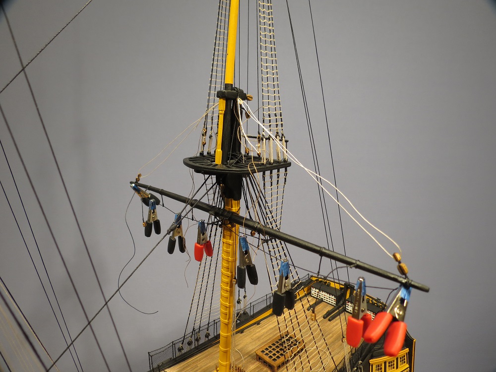
The "pin to mast" is perhaps the most helpful tip in simplifying rigging. I've mentioned it before but only in passing. Not original. I picked up the idea from Bob Hunt.
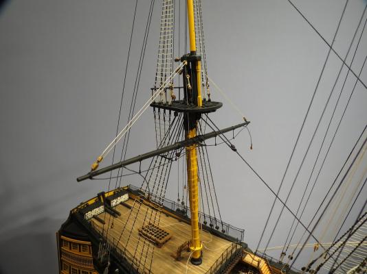
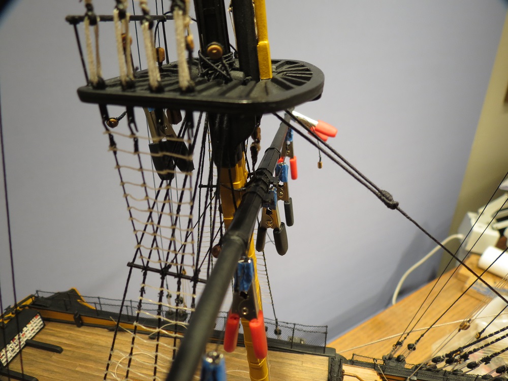
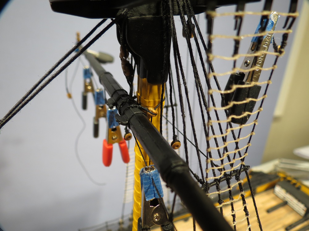
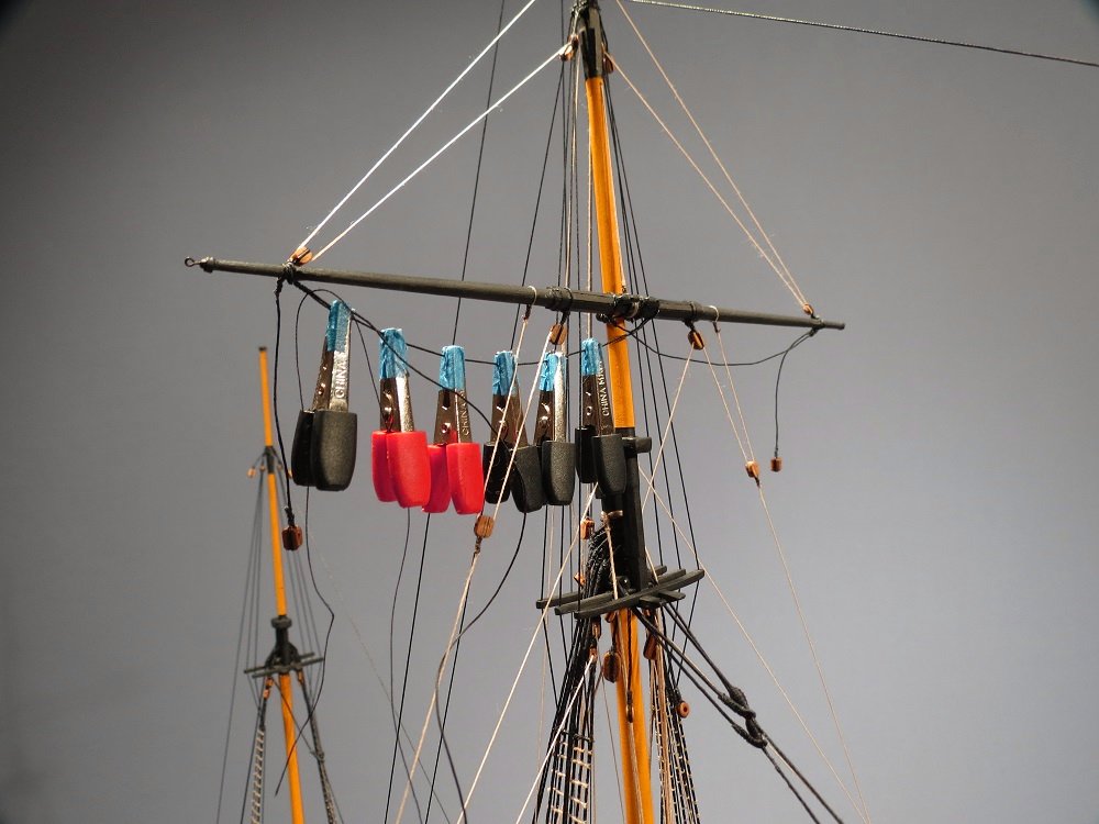
In the real ship, yards have great weight placing tension on lifts, slings and jeers. On the model, the small dowels are so light that tensioning support rigging simply raises the yard. By pinning the yard to the mast, one can tension the lifts, slings and pendants without the counterpull of down hauls, yard sling pendants, etc.
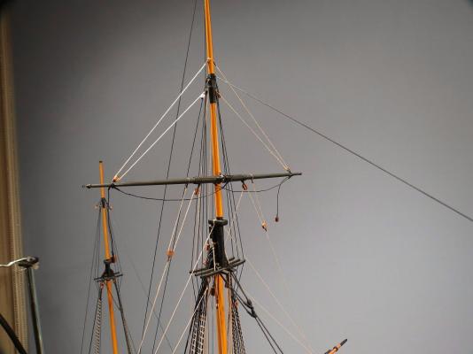
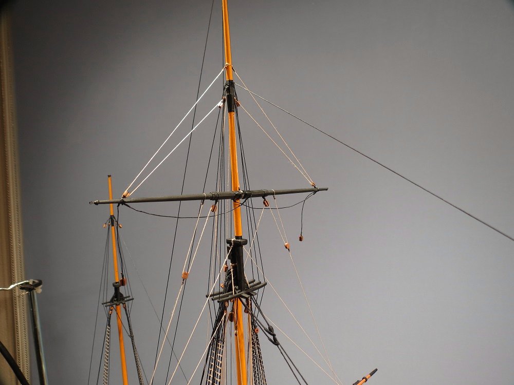
Many, perhaps most of us, already use this technique, but for those who are rigging for the first time, or who have trouble adjusting tension, the "pin" greatly simplifies the process. I drill a hole in the yard and the mast and glue the pin in the yard (5-15 sec. C/A). Adding glue to the pin, the yard is placed on the mast. After about 30 seconds, I move the yard ends slightly up and down, and fore and aft. The yard is held firmly to the mast but allows enough movement to level the yards with the topping lifts and align the yards athwartships with the braces. The pin is not visible from port or starboard. The port view shows the single truss pendant.


Truss pendant tackle.
Topping lifts rigged but slack. The hole in the topmast for the topmast yard pin can be seen.

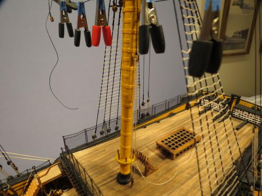
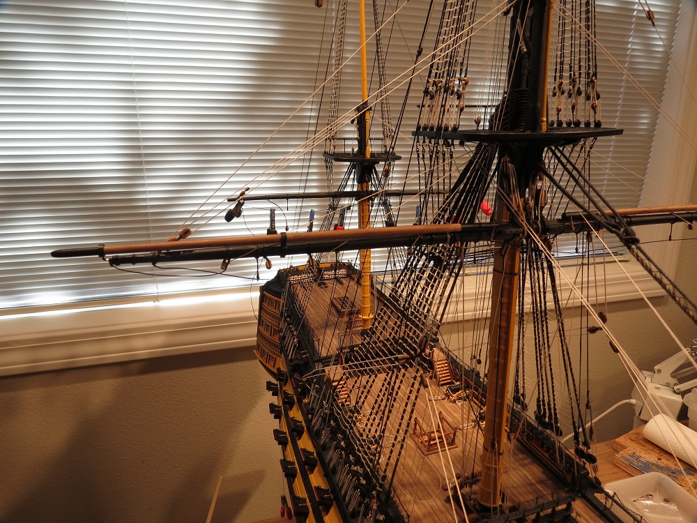
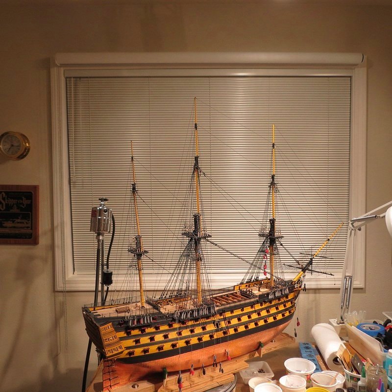
A lucky break at the Kirkland Shipyard. Venetian blinds help to level the crossjack yard.
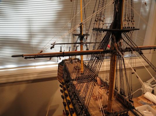
Topping lifts are tensioned to level the yard.
- freewheelinguy, canoe21, bhermann and 9 others
-
12
-
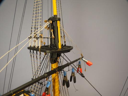
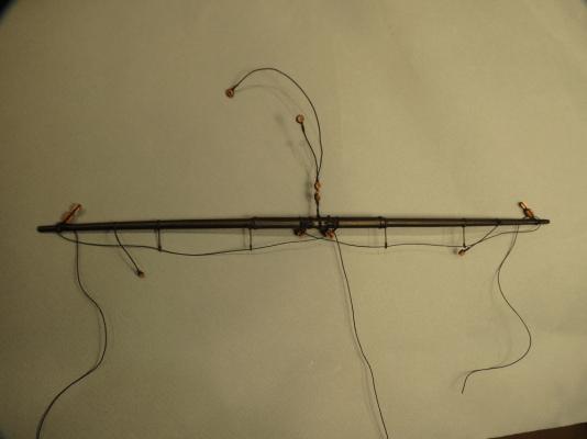
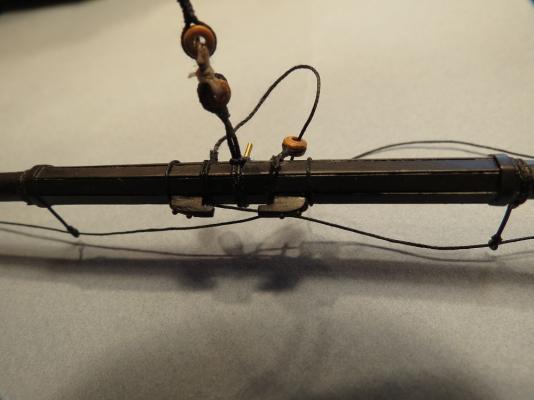
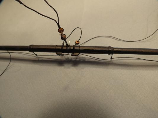
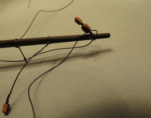
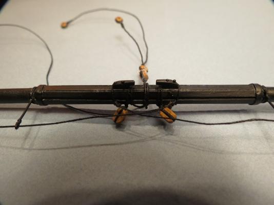
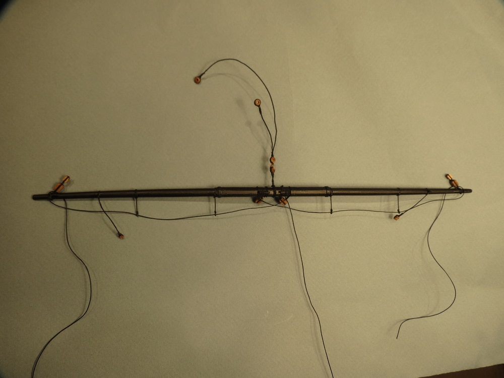
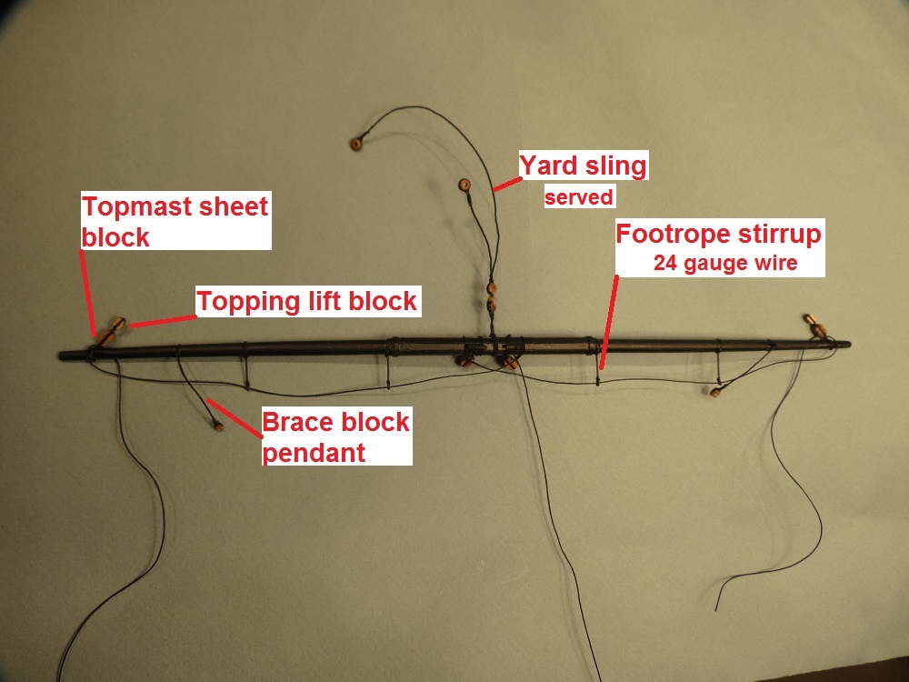
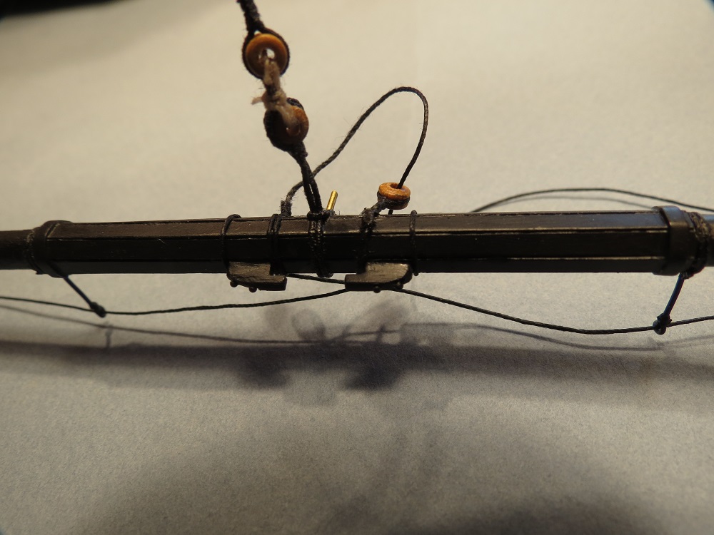
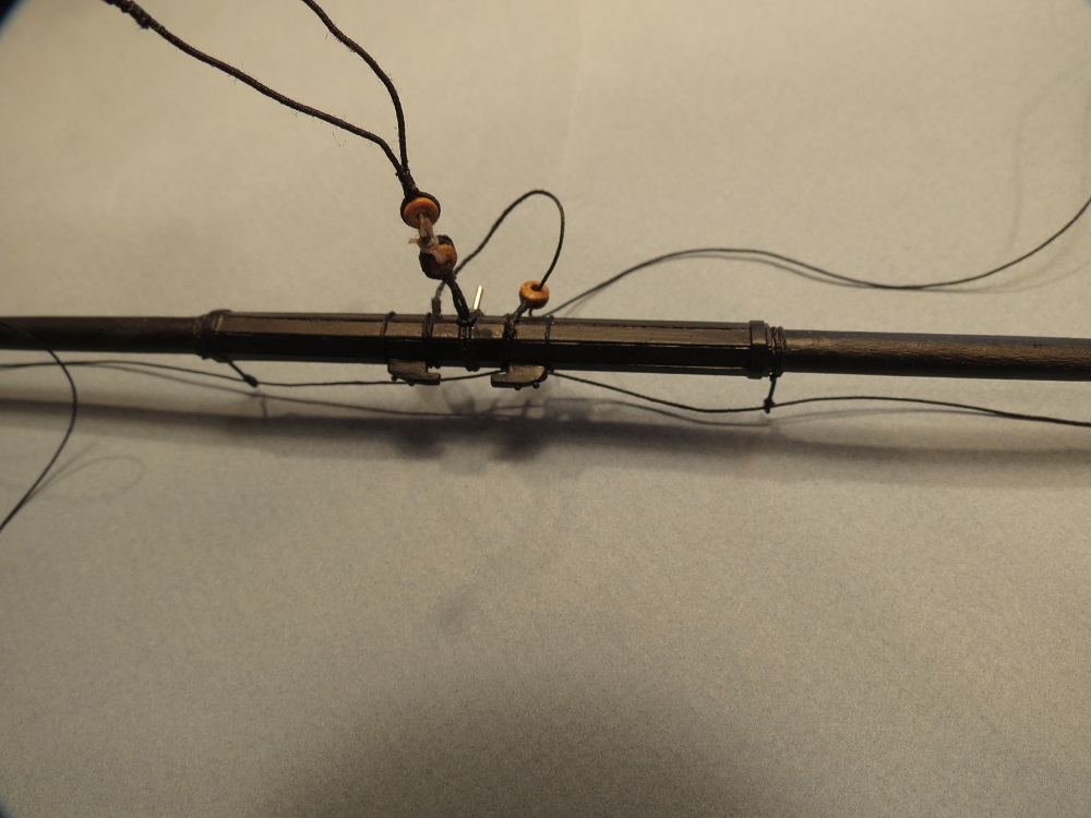
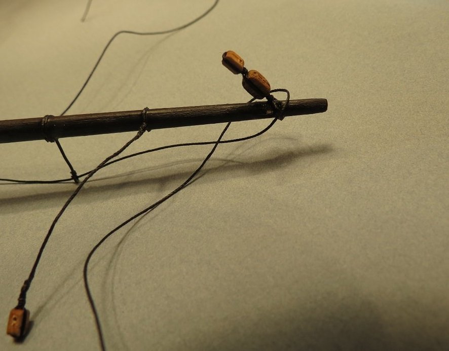
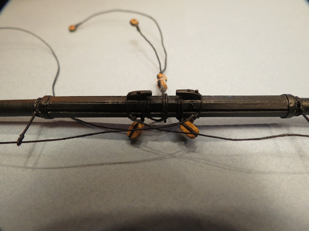
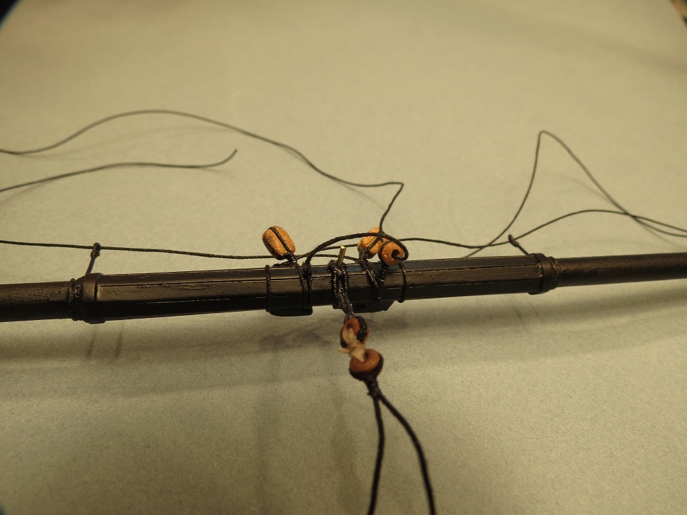
RIGGING THE CROSSJACK YARD
The first two photos show the served yard sling, foot rope stirrups (24 g. dark annealed steel wire), brace block pendants, and topping lift blocks and topsail sheets blocks stropped together. Since no course is attached to the crossjack yard, there are no clue, sheet or tack blocks.

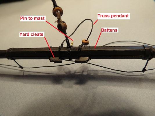
The next wo photos show details at the center including the single truss pendant, battens, yard cleats and the pin to the mast. Reference to the "pin" is made in the next post.

-
-
Grant, This just in. The JoTika rigging plans show brace block pendants on the Foremast yard, topmast yard and topgallant yard, Mainmast yard, topmast yard and topgallant yard, Crossjack yard and Mizzen topmast yard. No pendant is shown on the Mizzen topgallant yard. Cheers, Gil
-
Hi Grant, I did get your message and responded with a fairly long reply plus three photographs. Of course I have no idea where it went after I pressed send. It's probably hiding never to be seen again. So here it is again and a very Merry Christmas (past tense) to you and yours.
You certainly raise an interesting conundrum. I think that by all your reading, you are correct in the distribution of the brace block pendants (not located on the topmast yards and topgallant yards). I also looked back in Longridge, McGowan and McKay's books and came to the same conclusion. On the other hand, I took my lead from photos of the real ship, as it has been restored (supposedly to Trafalgar status). In some ways I suspect we are both right. Longridge is the best source one could ever find, however, it is based on observations made 60 years ago and on the restoration of the Victory in 1922. But then McKay's drawings reaffirm Longridge's statments. I'm at something of a loss since in cleaning out papers and old manuscripts, I apparently threw away the JoTika plans for the braces. JoTika kindly mailed me a new plan sheet but I haven't received it yet. I think further clouding the issue is my belief that different captains, sailing masters and bo's'n mates altered rigging to their own preferences. An example: adding bentink shrouds to stiffen the rig to point slightly higher to the wind and gain the weather gage on an opponent, or changing the rake of the mast to improve sailing performance and reduce weather helm. I think we'd have to talk with Captain Hardy for the real answer.
The attached photos of the real ship clearly show the yard tackle pendant on the lower yard, and brace block pendants on the topmast yard and topgallant yards. Is it correct????? From the point of view of presentation, I like the look of the pendants so I'll probably keep them.
Thanks for the fun of comparing notes, and a Happy New Year. Gil


-
Floyd, You can see that I chose the easy path. Hanging a sheet each time for a photo would be a pain.
John and Lawrence, Many thanks and a timely Merry Christmas ( 9:30 pm in Sidney? ) and wishes for a great New Year. Gil
-
Hi Len, No stops on the Lazy Susan. Not a bad idea though. It certainly helped with tensioning the shrouds and backstays, and leveling the yards with topping lifts. I've held off on the driver boom since it will limit the swing.
Looking forward to your build log Daniel.
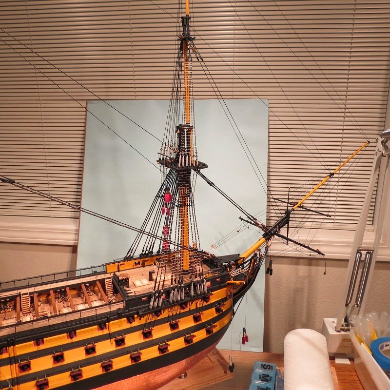
Floyd, After Mike Graff's photography workship, I tried posterboard which was inadequate, and finally found a baby blue pull down shade. If I painted some clouds on it, would it look more real?
- mtaylor, Blue Ensign, Sjors and 4 others
-
7
-
Daniel, I couldn't match your beautiful work on the Victory's anchor cable, but did rebuild the windlass on our boat to raise 500 - 700 lb. of anchor and chain. A bit small for the Victory.
Jerry, I'm still at the amazed stage of the white whites and bright colors.
Popeye, Where can I find a copy of your "Modelers Creedo?" Sounds interesting.
Daniel (Sailor), I looked at your bio and was astounded. I was also a lieutenant in the Canadian Navy (Reserve) and as a midshipman, spent time on HMCS Sioux (tribal class destroyer) and HMCS Antigonish (Frigate), 1951 - 1954. AND built models of the Cutty Sark, USS Constitution and of course the present Victory. Dream on! Our dream came in 1999 - 2002 when we took our boat offshore for three years and 30,000 miles. I couldn't find a build log, but hope you'll start one before getting too far along.
Nick, (Pompey2), Your Victory is a delight to behold. I'm looking forward to seeing the rigging come to life.
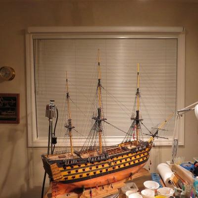
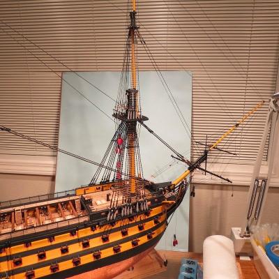
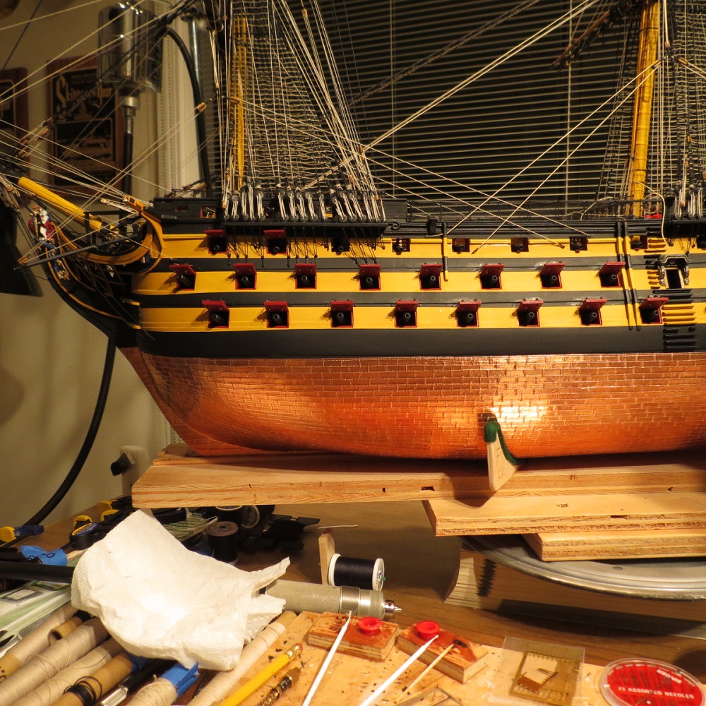
And finally, finishing up the Main mast topgallant yard. Adjusting the foot ropes.

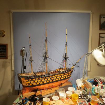
The state of the ship before progressing on to the Mizzen Mast. Click to enlarge.
Cheers, Gil
- Blue Ensign, RGL, Sjors and 9 others
-
12
-
Many thanks Popeye. You may have bailed me out.
And Klaas and Jerry, I sincerely appreciate your comments.
A REFLECTION........Why do we spend so many hours building model ships that were in their prime over 200 years ago or more? We each have different priorities, however many are common to the majority of us. For me, the satisfaction of working with my hands to produce a replica of a ship with beautiful lines tops the list. We learn a great deal about ships of the day, and how they worked, sailed and crossed oceans, and perhaps more than we need to know about the source of our immediate project. I'll never anchor our boat again without thinking of Daniel's dissertation on anchoring the "Victory." (I'd need ten men to raise our anchor without a power windlass.) We strive for authenticity in our models, which of course can lead to obsession over details, while sharing with great joy the interchange with our friends on MSW. They praise us when we get it right and keep us humble when we miss the mark. But most of all it's dialog with friends from around the world.
We build model ships for the love of the sea, and dreams of crossing the horizon to who knows where. "If I were a lad in 1805 going to sea........................."
We build the models for presentation, but since larger models don't travel well, our audience is limited to close friends and family, unfortunate neighbors whose eyes glaze over when told of over three thousand copper plates or serving the shrouds and grand and great grand children who call it a "Pirate Ship." Few of us will ever crack the door of a major museum, so the venue will likely be the front hall, back room or where ever space allows. Judy says, "The house is a museum."
Net result? It's a passion and it's fun.
One other observation. Vindicari noted that my Yellow Ochre seemed brighter and more Yellow than the real ship. I responded with a "learned reply" about mixing paints, effects of lighting, etc............and then I had cataract surgery three days ago. You guessed it. With the unoperated eye, the "Yellow Ochre" looks pretty good, while through the operated eye, it's brighter and more yellow . So from now on, one has to consider the age of the old geezer and whether he has cataracts. Nuff said.
Merry Christmas and Happy New Year. Gil
-
More on Klaas and Jerry's comments. I had to change to Firefox in order to post photos.
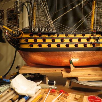
From the point of view of presentation of the model, it seems a shame to paint over the black bands, pintles and gudgeons with copper since the black shows off the detail of the bands, bolts, etc.much better than a uniform color. The answer may be to paint the rudder fittings with copper paint darkened with umber to simulate the darker color of bronze when compared with copper. In fact I'd over darken the fittings to increase the contrast and highlight the detail.
The photos show the present rudder fittings and a photo of the restoration of the USS Constitution showing the somewhat darker color of bronze compared to the copper plating (National Geographic photo). When I have finally come up with an appropriate color, I'll add a photo. Cheers, Gil


- ZyXuz, fnkershner, mtaylor and 1 other
-
4
-
Hi Klaas, Perhaps not the definitive answer. Bronze is an alloy of copper and tin or other elements such as today's silicone bronze used in boat building for fasteners with wood such as teak decks. Bronze was certainly available since bronze cannons were in use before giving way to steel. In any event your observations are undoubtedly correct since iron based pintles and gudgeons would be degraded by electrolysis. It's fun to share the ideas. Gil
-
Hi Jerry, Oops! Another senior moment. I'm looking in obscure books while there it is, right under my nose in the manual. Many thanks for the heads up Jerry. Copper would seem too soft a metal for the load while bronze certainly could handle it. Does anyone have the definitive answer?
Cheers, Gil
-
Sjors, Thanks. Gutermann is also my favorite for seizing and whipping, as over splices. I like a darker whipping which seems to better define a "splice" and perhaps simulate use of an oiled or waxed thread. For those unfamiliar with the terms, whipping is a heavy thread or cord used to wrap a rope end to keep it from fraying or a splice from unraveling and weakening, whereas serving is done with a heavier line to protect a larger rope from chaffe.
But enough of that. I need to climb the ratlines and finish rigging the main topgallant yard. Cheers, Gil
- mtaylor, freewheelinguy and Sjors
-
3
-
Klaas, Many thanks for the reference, one that I do not have. However, it makes sense since it was about the same time that it was realized that iron nails deteriorated in copper sheathing. None of my limited references make note of the metallurgy of the pintles and gudgeons. Thanks again for the resource.
Cheers, Gil
-
Thanks Lawrence and Popeye. And Gerty, as I mentioned on your log, I think your Chesapeake Skipjack may be my next project. When we were on our boat in the Chesapeake, the one we saw was like living history. Sort of like seeing the C.W. Morgan being restored at Mystic Seaport. I spent the whole day crawling about the ship and now want to build the model. As I've said before, I think we were born about one to two hundred years too late.
Sjors, the "tutorials" are pretty simple and perhaps only one of several ways to do it However, it may help someone starting out. I've used the threads from the JoTika kit which I think are very good, along with a healthy dose of extra Mantua line from a previous build and a number of trips to JoAnns fabrics, a local fabric and sewing store. Fine lines for serving and those used for seizing splices etc. were added from the fabric store. My only regret is that I didn't soak the lines in tea or dilute stain before rigging since the "natural" line supplied appears almost white in most lighting, much lighter than sun bleached Manila hemp. Of course, if someone isn't as old as I am, one might never have worked with Manila line and wouldn't notice the difference. When we reach about 90, we should have all the answers if we can just remember them.
Cheers, Gil
-
Grant, You've raised interesting conundrums we've all faced and I suspect there is no definitive answer. On the Cutty Sark and the Constitution, I did all the mast and yard work including blocks, foot ropes, etc. off the ship. They were added when ready to begin shrouds and stays. The advantage was that both ships were mounted on their support pedestals so that work on the masts off the ship, placed less stress on the supports. The Victory however, is in a very firm cradle support. Still the masts were completed off site and added when complete. The yards were completed off site simply because it is far easier to work on them at a desk than when mounted. Trying to strop a block, adjust a foot rope, or add battens to a yard over head is too much for this old fellow. It seems more satisfying placing the masts first, then adding yards as it would be done during building or a refit.
As to the order, I tend to start with main and fore yards going up and aft, holding off on sheets, tacks and braces until other lines have run their course to the belaying pins and bitts. Still, my fingers and instruments seem always to be a bit too short. Is this like Gulliver building a doll house for a Lilliputian child? Sorry Grant, not much help here.
Popeye, you talk about the Whisker Boom or Boomkin. On the Victory, the inboard end is fixed to the knighthead, supported at the rail and of course ends with a block for the main course tack line. Looking back in your log (great fun by the way) there is no knighthead on the Gothenborg and I am at a loss at to the inboard attachment. No help here as well.
Joe, it's always fun to know you're out there keeping us honest.
Vindicari, I appreciate your comments. I did not use the excellent paint sets available, since working in my den, I chose to use only water based paints. However, by mixing colors and testing results, I came up with a fair substitute. If you go to page 2 of my log, the first several photos show the result under natural lighting, the use of incandescent lights which change "Yellow Ochre" to lemon yellow and of course flash which changes all the colors. Another reference shows the same observation. The JoTika Victory build site shows rather bright yellow in photos but also shows the model in natural light. Go to jotika-ltd.com/pages/1024768/Victory. On page 9 of the build site, click on the first photo and it should show the Yellow Ochre without Halogen lighting.
Cheers, Gil
-
Lawrence, I'm glad it helped.
Modelman, Will not likely get to Finland again but we'll be in touch through MSW.
Ron, Thanks, but your brig "Oneida" is a gem. What a great transition from kit to scratch building. The decking and planking is exquisite and I am so glad I can paint over my mistakes. If I live long enough, perhaps I'll handle wood like you do.
Continuing on with the main course clew garnet (clew line), clew block, tack and sheet. The main sheet brackets and ring supporting the aft sheet block.
A side view for orientation, showing the fore yard tack going forward to the boomkin and the fore yard sheet going aft. Also showing the main yard tack.
The fore yard sheet running down to the right. The main yard tack, down to the left.
The main yard sheet, originating from an eyebolt in the hull, passing through the sheet block, returning to the aft sheet block, supported by a lanyard through the bracket and ring.

One could argue that the sheet interferes with the gun port lid, however, when clearing for action, the courses (lower sails) were generally furled to avoid the firey wad being blown back into the sail causing the sail to catch fire. Have we all read the Patrick O'Brien series? Cheers, Gil
-
Lawrence, There is no joint around the mast. Problem solved. Each pair of shrouds is one line. The line is served where it passes around the mast to below the top (or one can leave the lines without serving). At each end of the serving, long tails are left to act as shrouds. Where the shrouds pass around the mast, they are seized together with 8 to 10 turns of finer thread and then both tails become shrouds. Usually both tails (shrouds) pass down one side, eg. starboard. The next pair of shrouds to port, then the next to starboard, etc. When the deadeyes are in place and tensioned, one can go back and forth between Port and Starboard to insure that the masts remain midline when viewed fore and aft. Here is where the Lazy Susan proves so useful. Hope that clears up the confusion. Cheers, Gil
-
Hi Lawrence, I'm not sure I understand the question. Are you talking about where the deadeyes are lashed together? Gil


HMS Victory by gil middleton - FINISHED - Caldercraft - 1:72
in - Kit build logs for subjects built from 1751 - 1800
Posted
Glen. Thanks. It did seem an imposing task at the beginning. You'll be bonded to the Victory for about as long as it took to build the original ship. I'm starting my sixth year with the old girl. Sit back and enjoy. There's hardly a challenge you can name where you won't find abundant help from other builders on MSW.
Lawrence, Great progress on your Victory. You are very kind, but just to set the record straight, this was my first go at serving lines. Pretty soon you will have done it, be an expert and showing newcomers how to do it.
Cheers,
Gil