


gil middleton
-
Posts
308 -
Joined
-
Last visited
Content Type
Profiles
Forums
Gallery
Events
Posts posted by gil middleton
-
-
Thanks Michael and Jerry.
Michael, I haven't delved into the 1600's. Good luck in your search.
Jerry, I agree with your outlook. I don't want to start another 6 or 7 year project. Might not be around to see the finished product. But small boats and small ships, go for it. Turkey time. Cheers, Gil
-
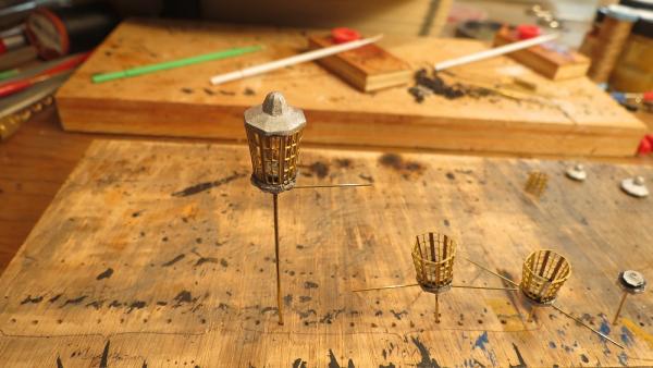
And the rest of the story.
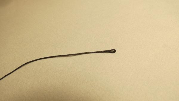
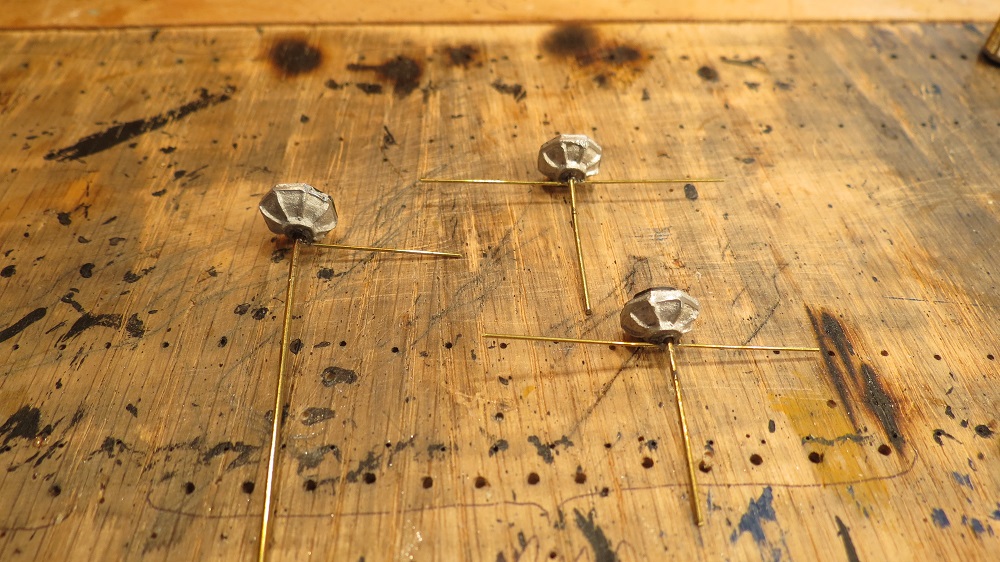
Both eyes formed
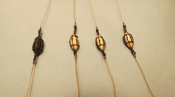
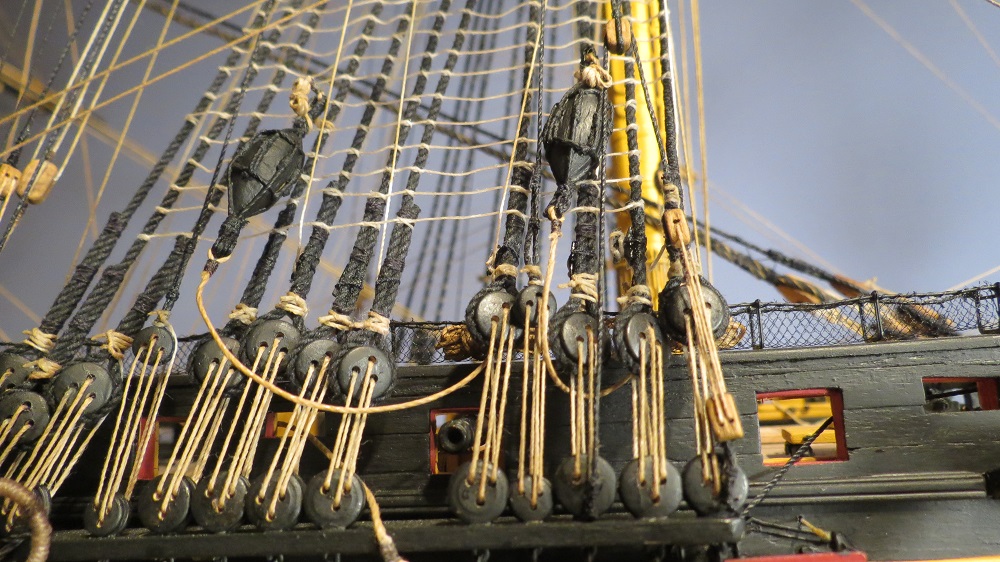
All nun buoys rigged. On the right, upper line for retrieving the buoy, heavier lower line to the anchor.
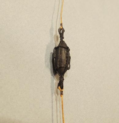
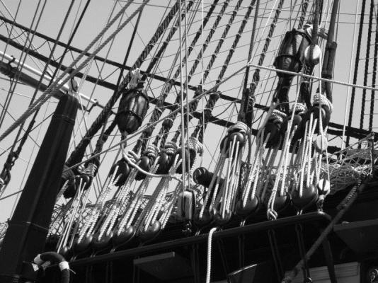
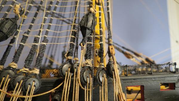
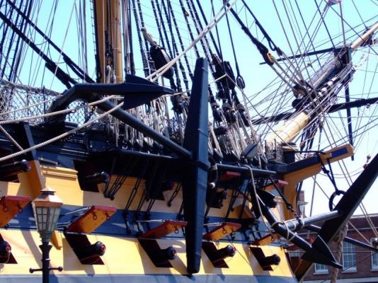
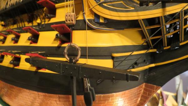
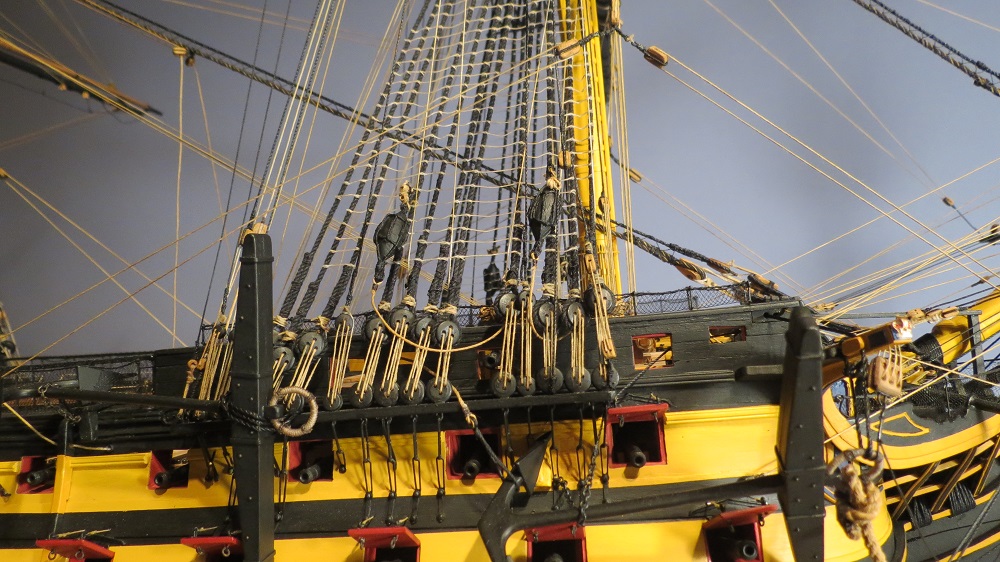
On the real ship, nun buoys lashed to the shrouds.
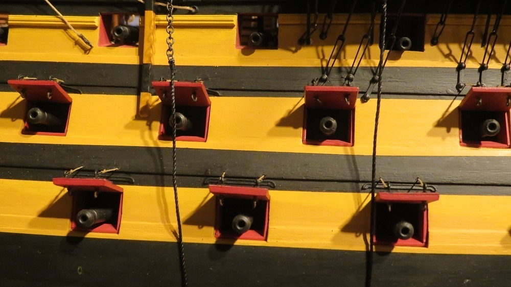
And on the model. Excess line to anchor stored in hammock net.


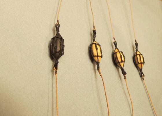
The close up appears rather rough, but gives the sense of tarred canvas and ropes over cork
Happy Thanksgiving everyone. Gil.
-
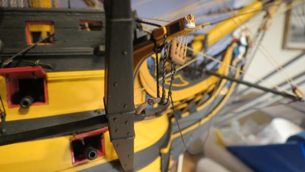
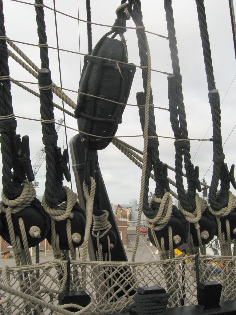
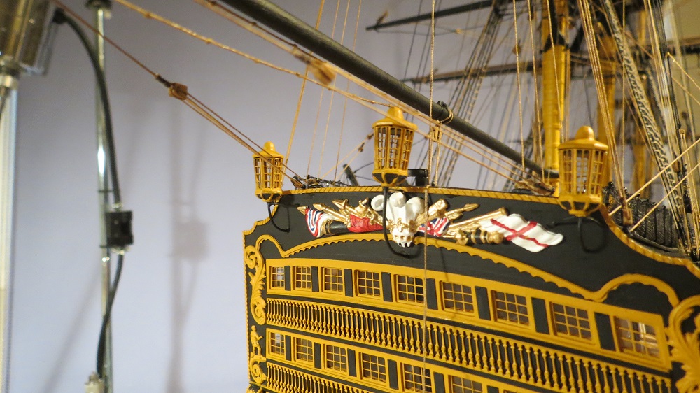
More details to add are the nun buoys used with the anchors. Seen on the real ship, these served to locate the anchors and by a line attached to the foot or fluke end of the anchor, the anchor could be pulled backwards to disengage the flukes with a fouled anchor.
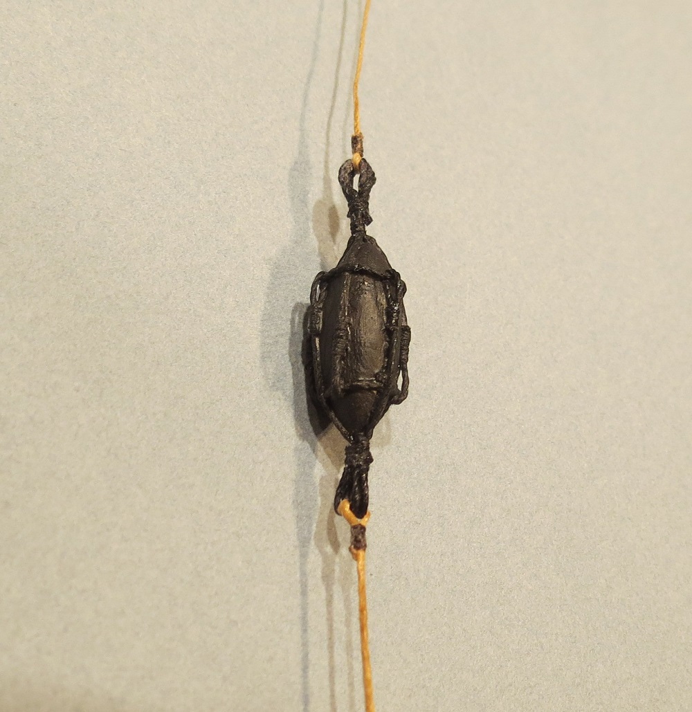
On the present ship, the nun buoys are rigged as they were described by Steel in 1794.
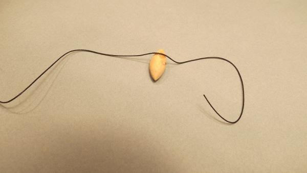
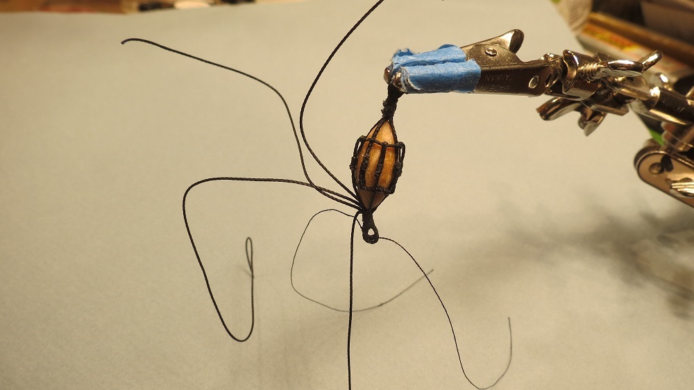
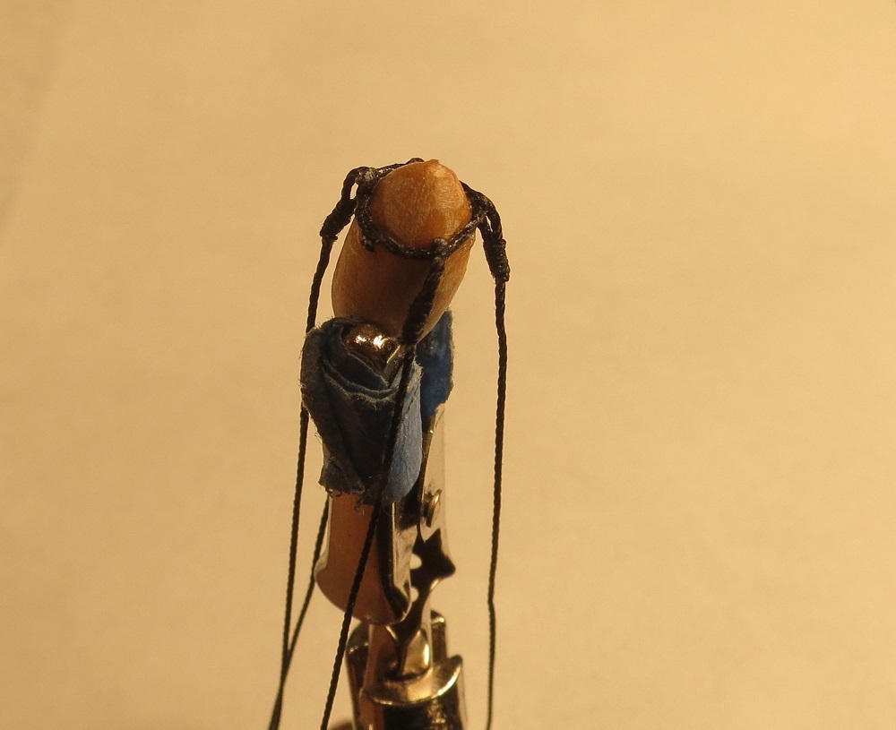
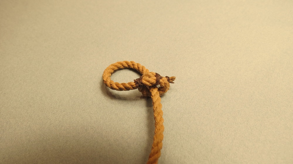
On a close up of the nun buoy, although rather dark, one can see the upper rope line forming a ring with lines eyespliced to the ring, running down to form a lower eye. The reverse lines run from the lower ring to form the upper eye.

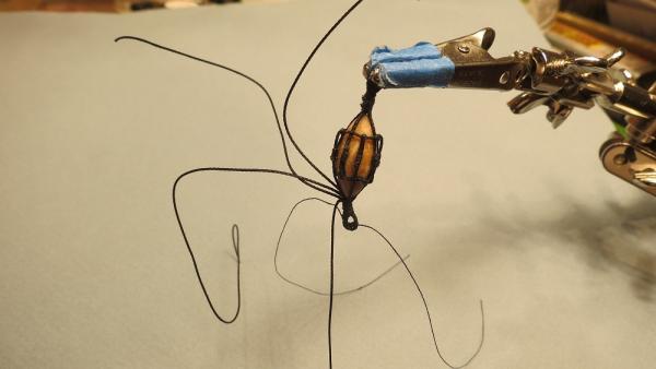
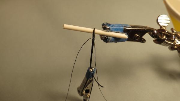
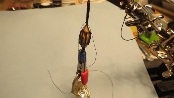
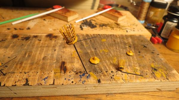
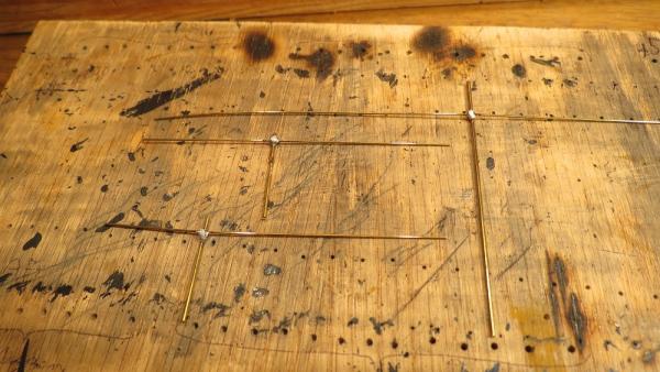
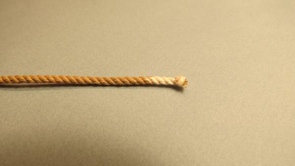
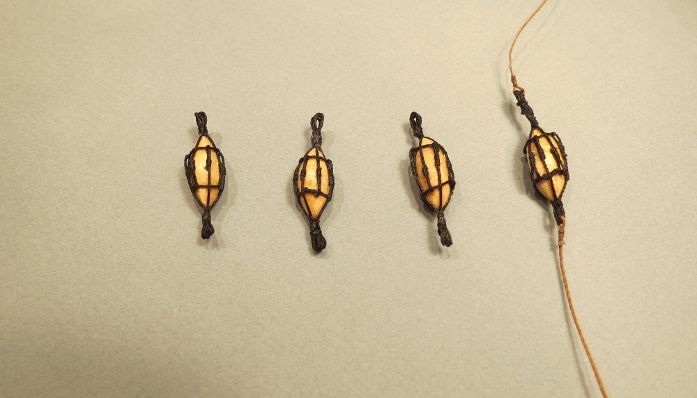
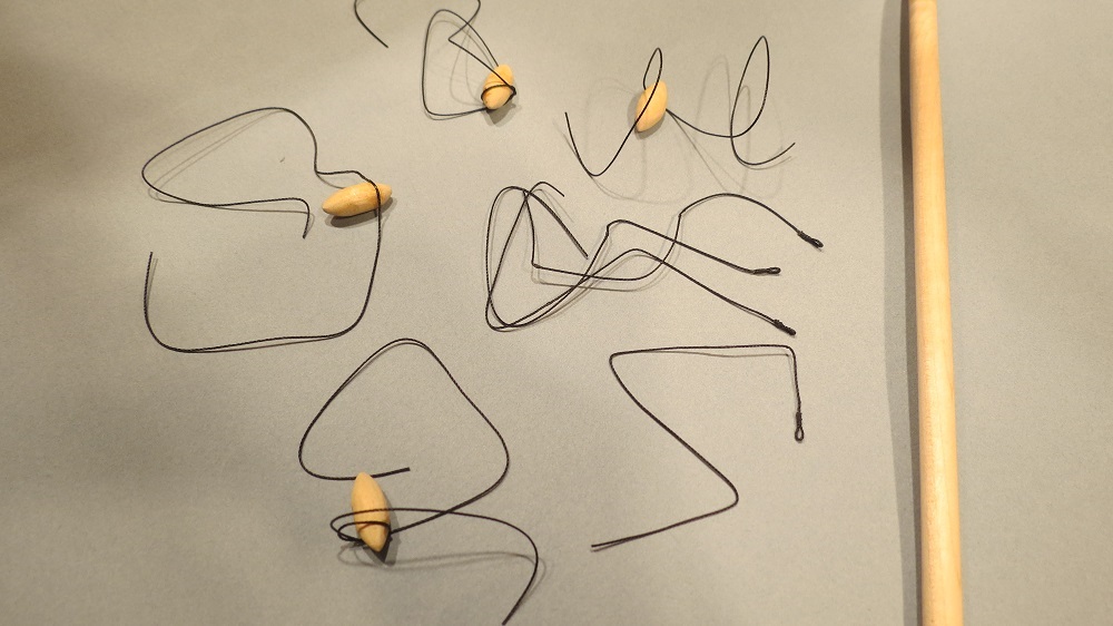
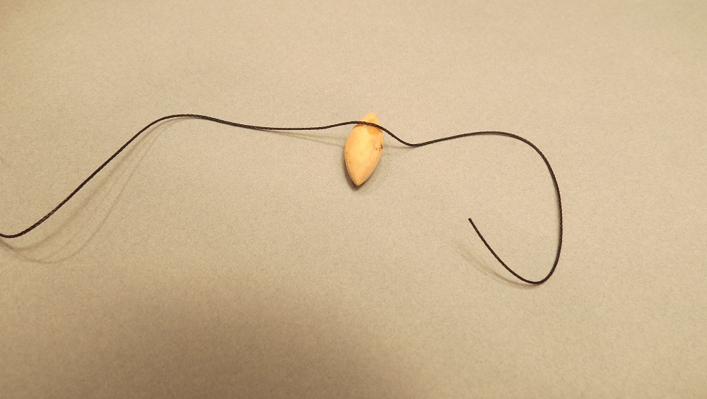
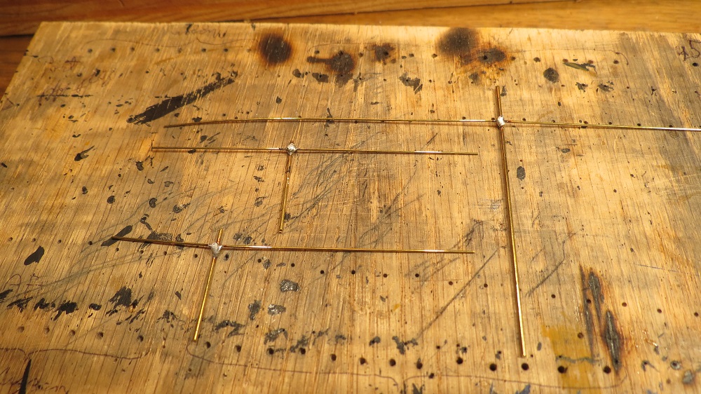
I hesitate to recommend this technique since it requires many "splices" but being rather compulsive, I decided to rig them as described by Steel. I suspect one could paint a vitamin pill black, glue it to the rigging and few would notice. But what's the fun in that. The buoys were shaped from a 7mm. dowel and the line to form a ring was glued to one side (C/A 10-15 sec.) to give a stable starting point.
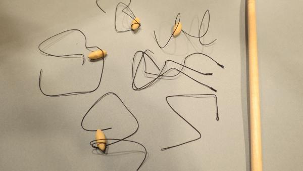
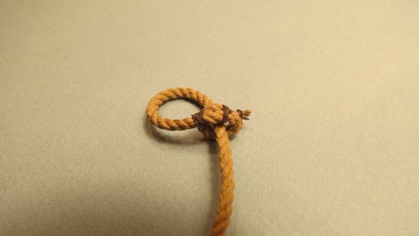
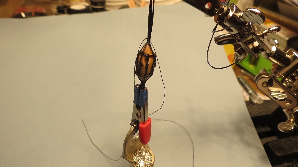
Lines with eye splices were attached to the ring line. Forming the eye splice. The upper ring line completed.
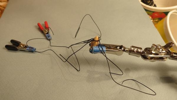

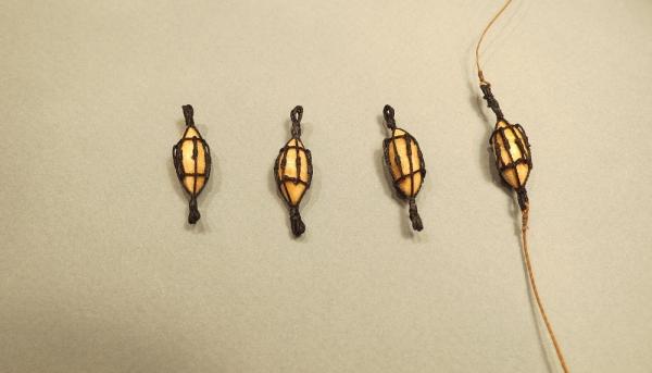
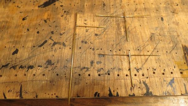
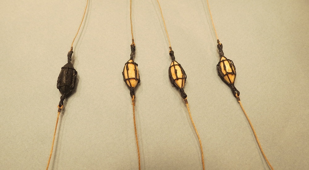
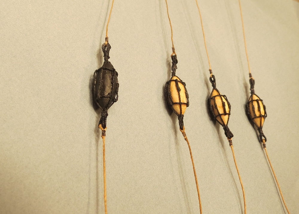
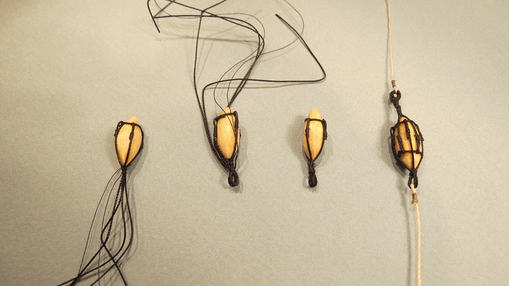
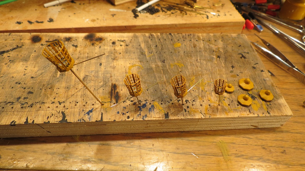
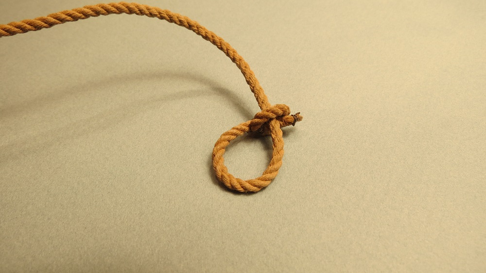
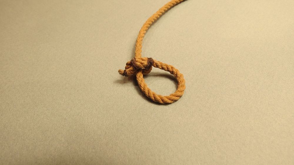
Four stages of rigging the nun buoys. From left to right,
Upper ring with eye splices and lines seized at lower end.
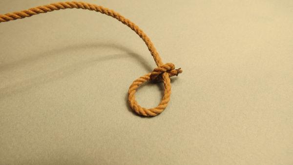
Lower eye seized.
Lower eye seized and trimmed.
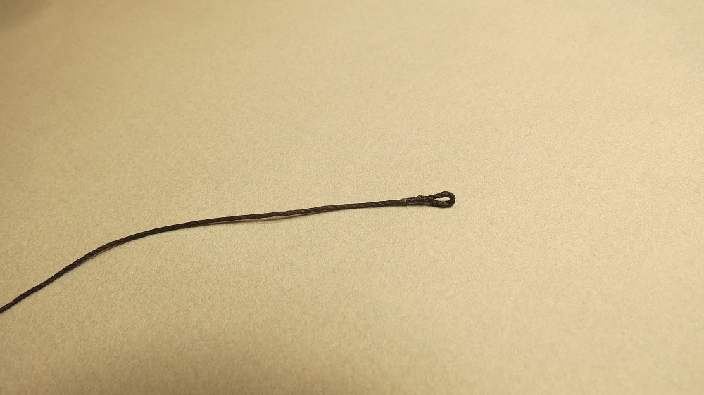
Reverse rigging lower ring line and forming upper eye.
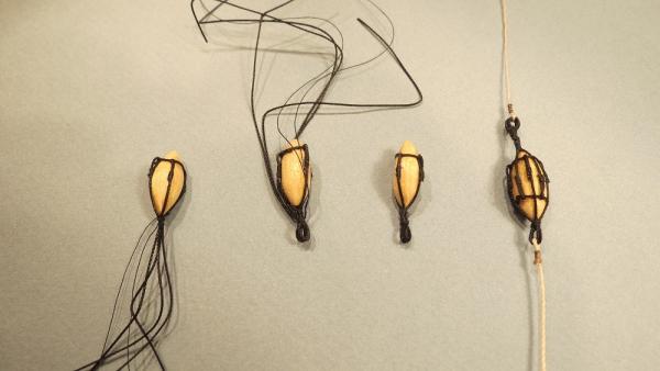
Seizing the other end.
To be continued.......
-
Many thanks Jack. Since I'm about to start on the ship's boats, I'll refer to your site for a heads up.
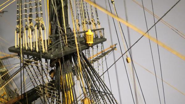
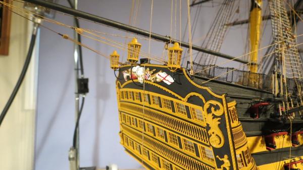
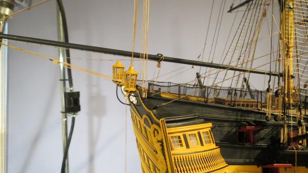
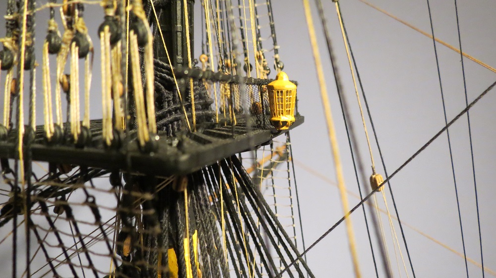
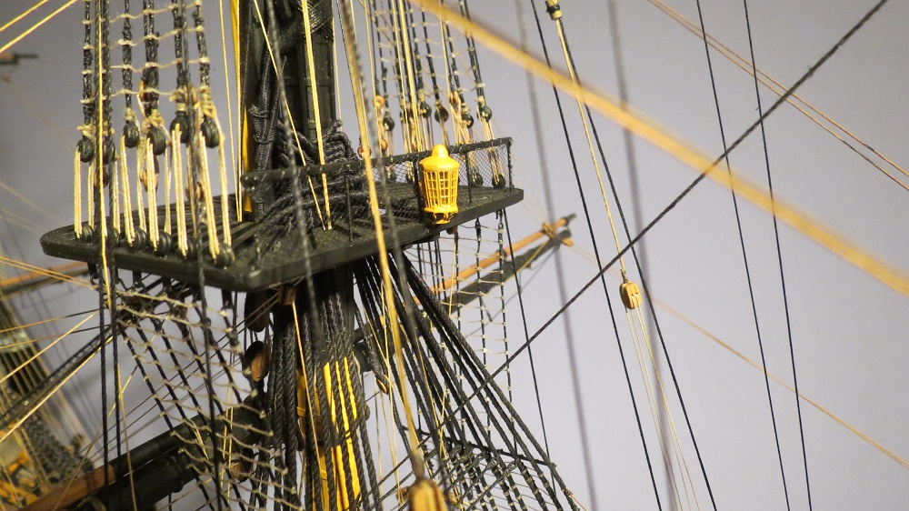
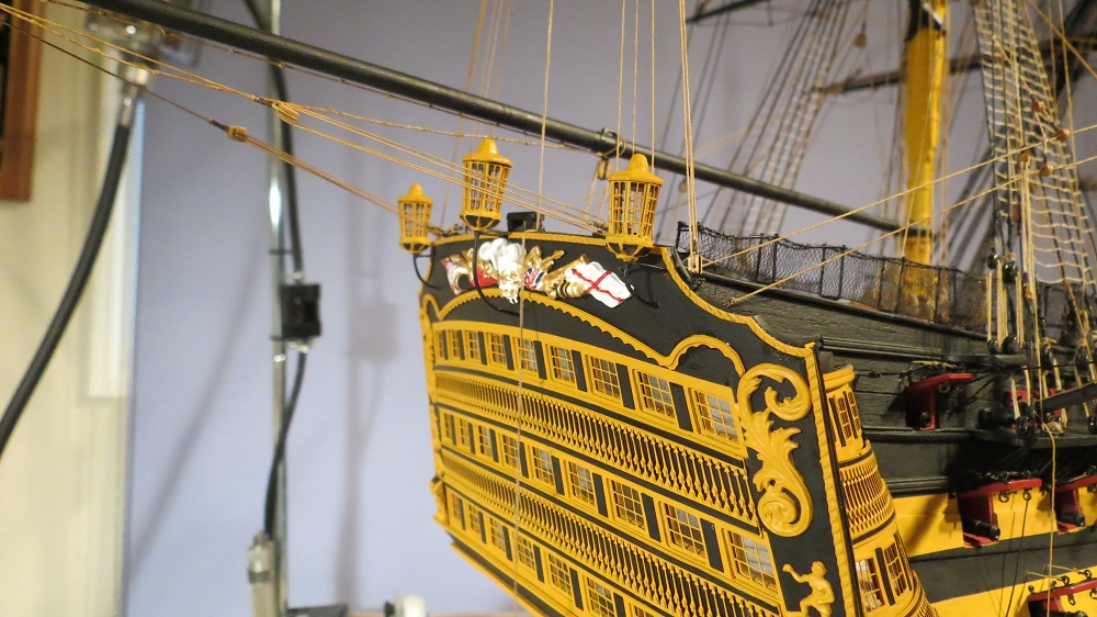
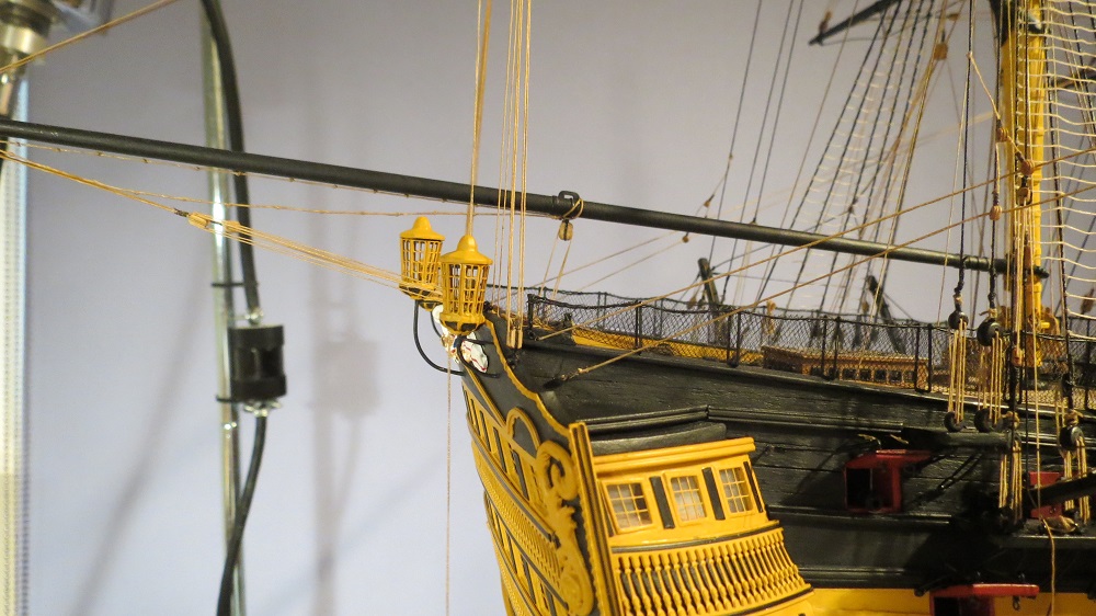
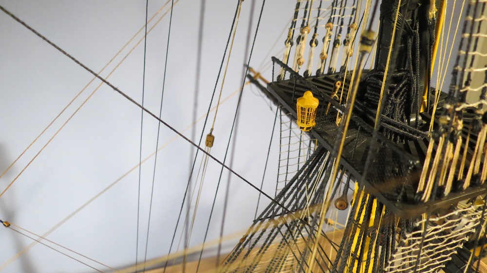
I had experimented with clear acrylic flat and clear acrylic semi-gloss for the glazing of the lanterns. It worked well, but was too opaque, rather like plastic milk carton appearance. The Micro-Glaze gave a much more realistic appearance. A couple photos show the outcome.

Gil
-
Thanks David, Alan, Mort, Edwin and Grant for replying. My apologies for the delay as I had a computer meltdown. It will probably be a week before I can post photos again.
Also, thanks Mort and Grant for the reassurance with Micro-Glaze. I had experimented with clear acrylic semi-gloss and flat but Micro-Glaze seemed to work better. More later. Gil
-
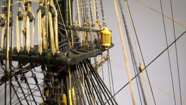
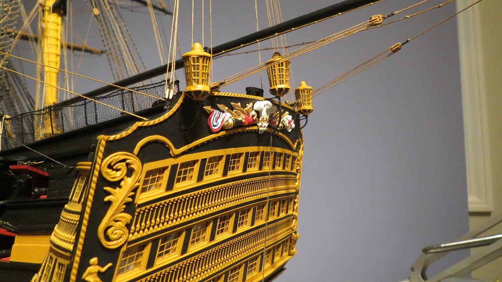
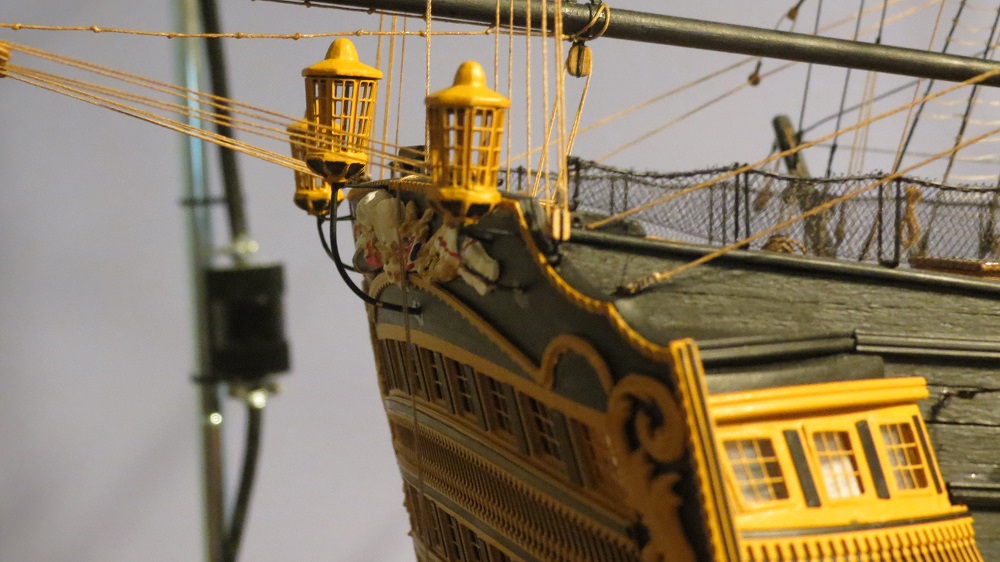
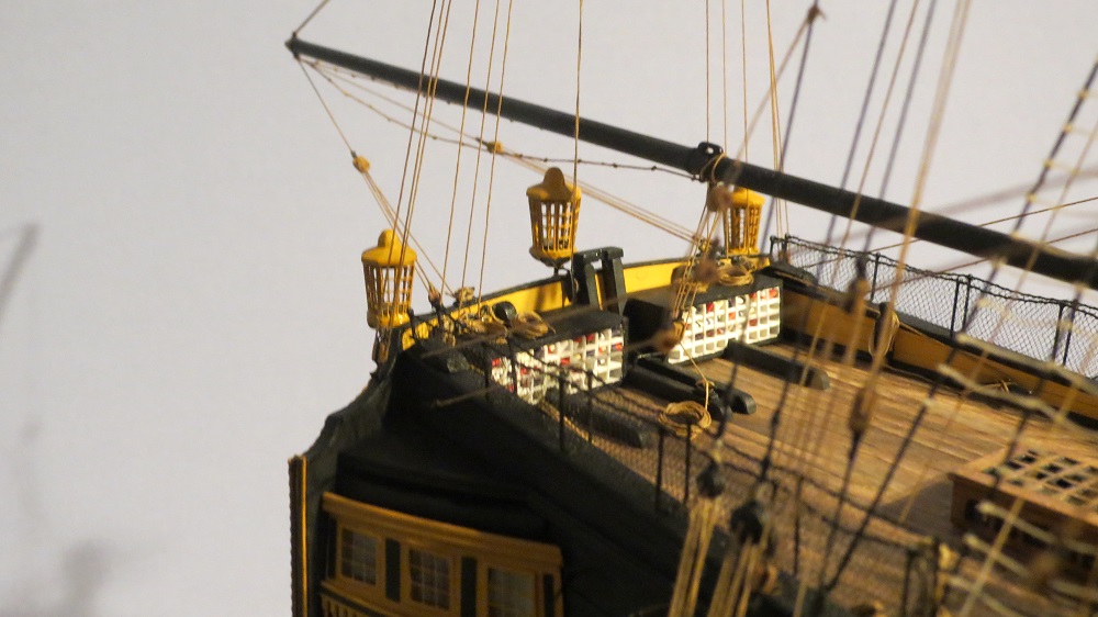
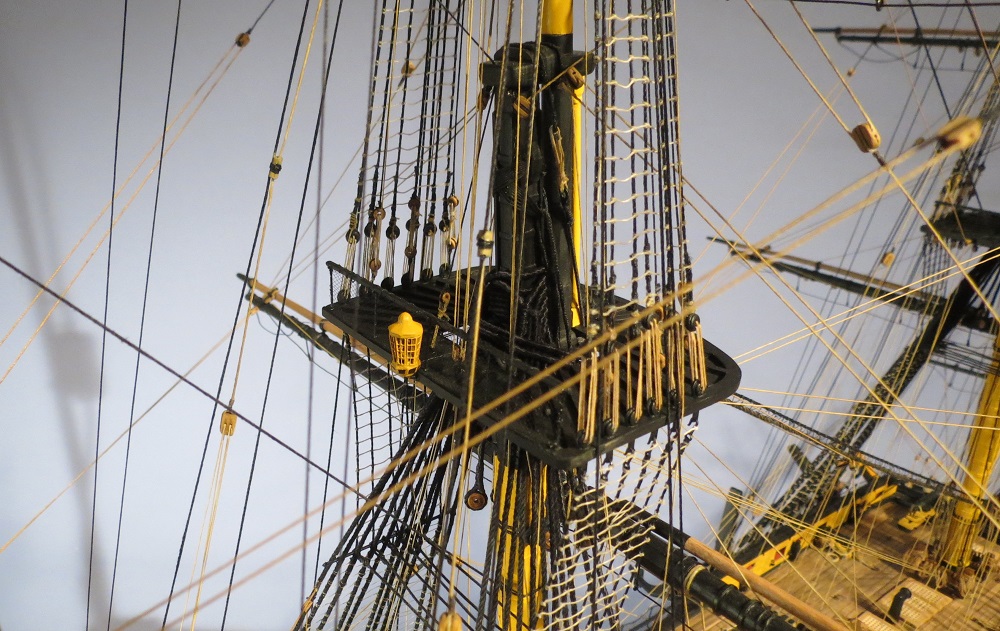
Lanterns and supports painted.

Lanterns mounted. The top of the lanterns have not been fixed in place in order to add glazing inside the lanterns. I'm experimenting with glazing. Has anyone tried the Micro Glaze from Micro Mark? And if so, does it stand up to handling?

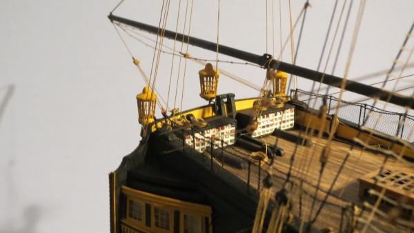
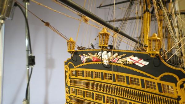
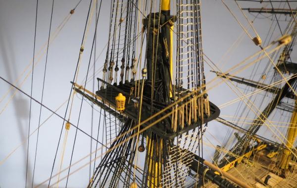
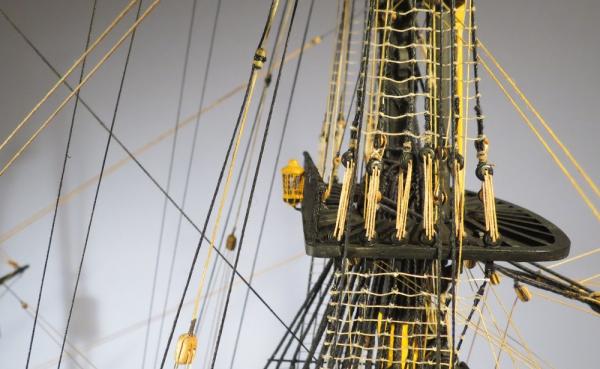
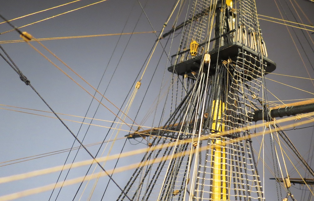
The smaller Admiral's lantern is attached aft of the main top.


-
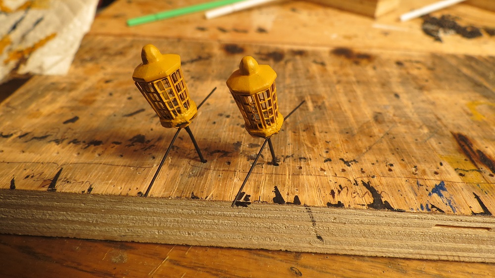
Moving on to the ship's lanterns. The JoTika kit has very nice etched brass for the lantern windows that can be bent to fit the base. Soldering the lantern supports.
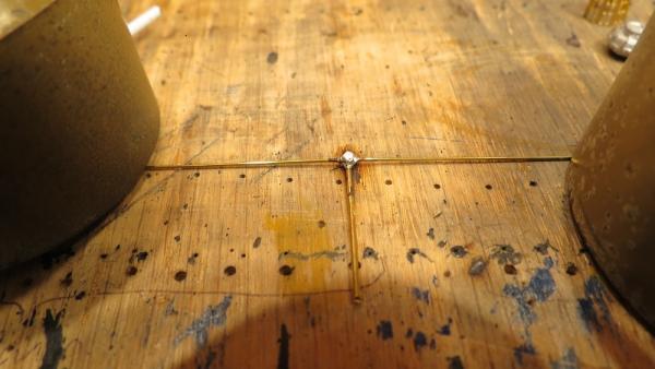
Solder points filed down
Holes drilled into the lantern bases for the lantern supports. Supports fixed with C/A glue.

Lanterns

- edmay, augie, mort stoll and 11 others
-
 14
14
-
-
-
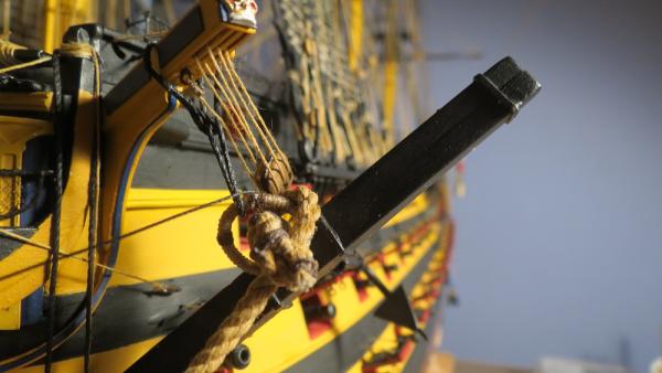
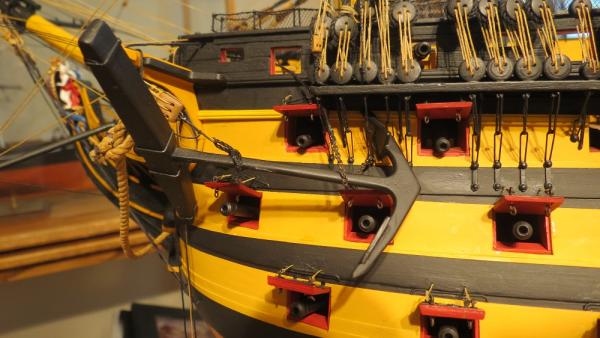
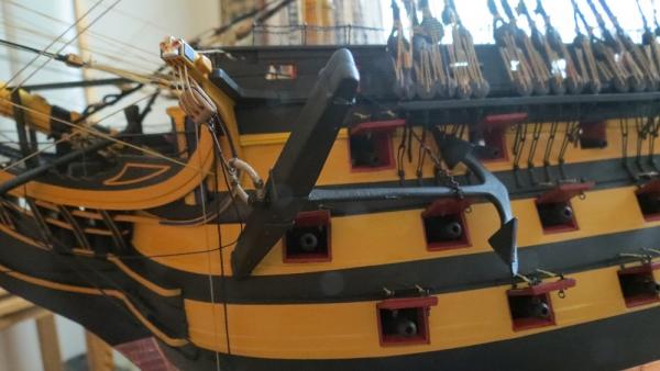
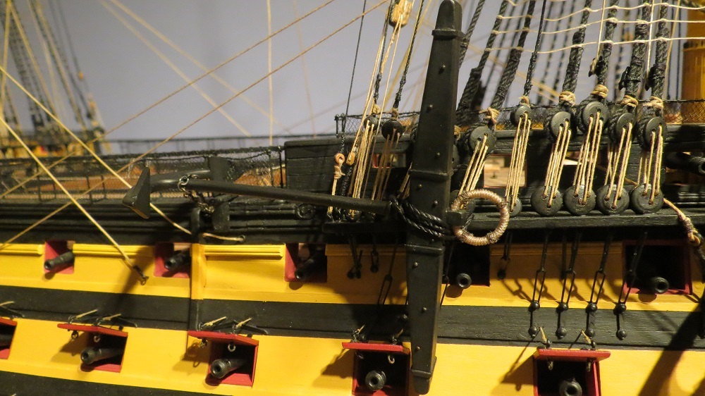
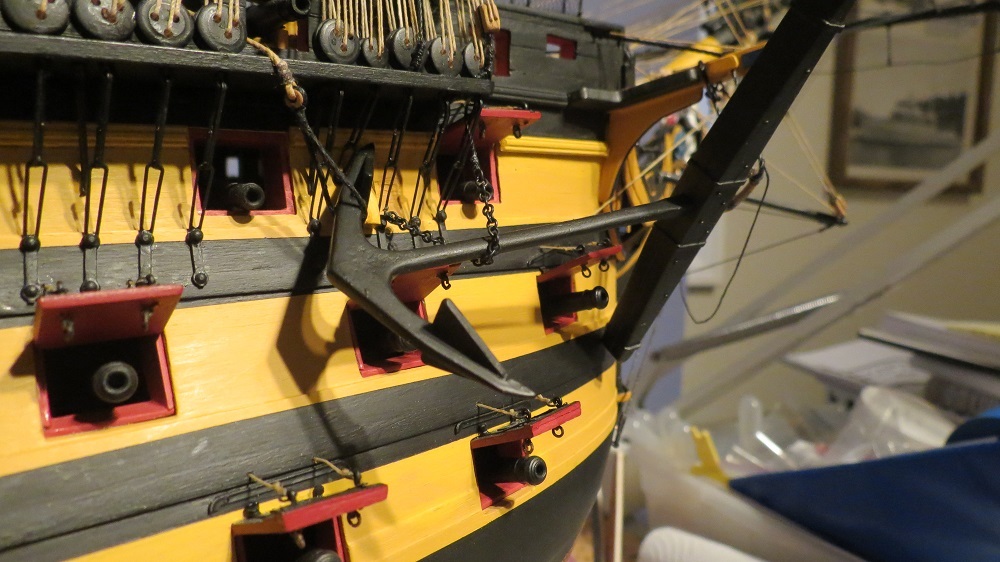
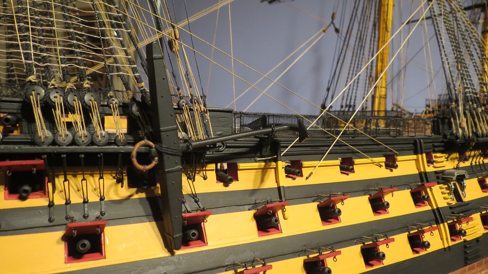
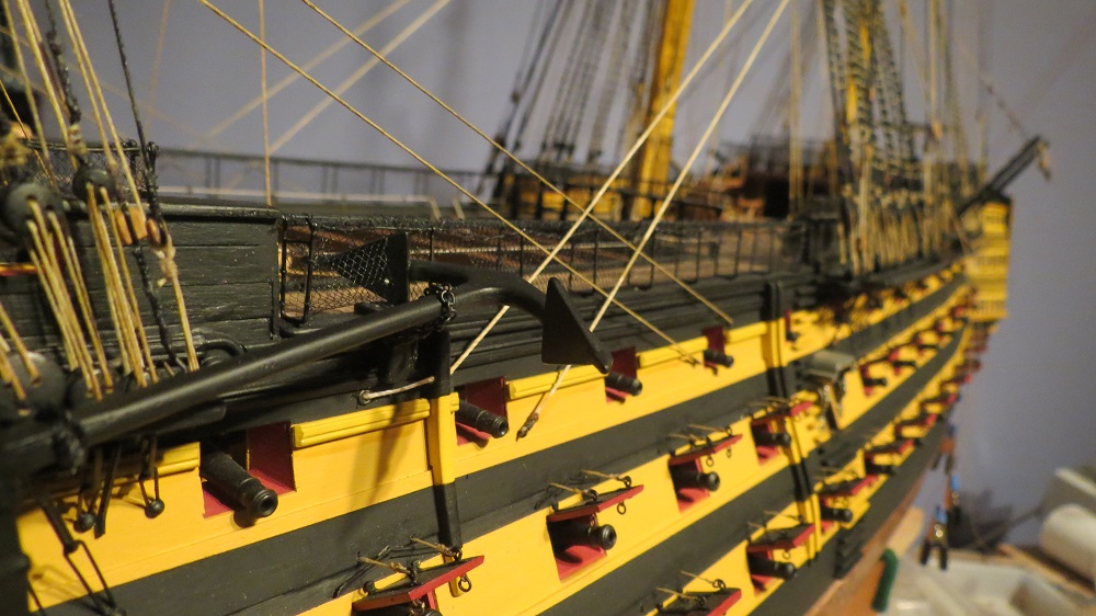
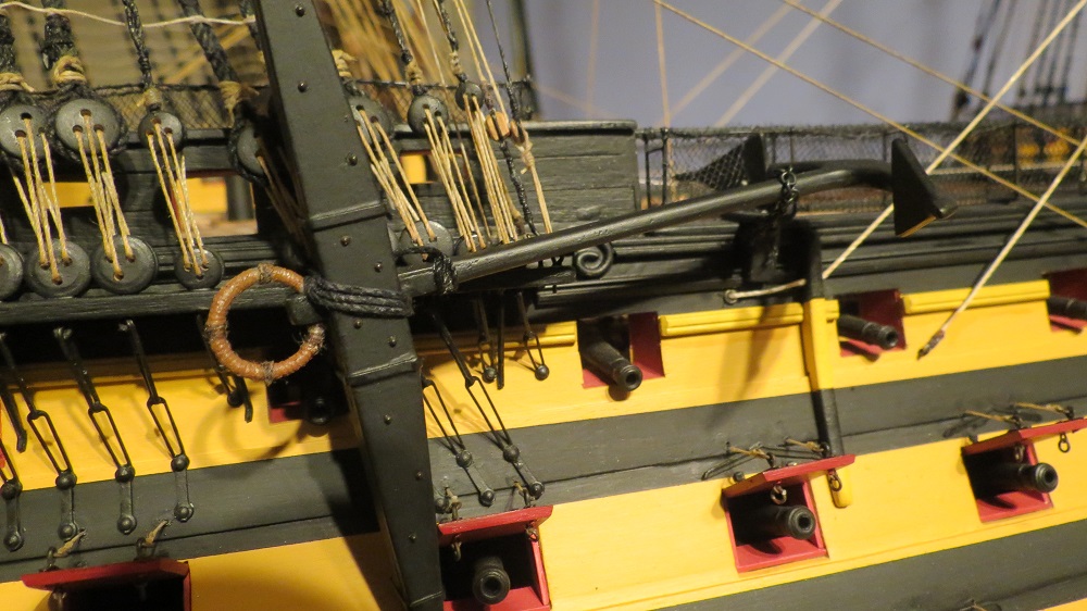
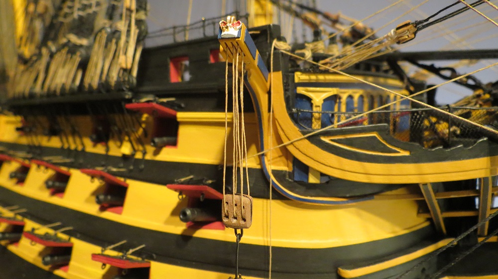
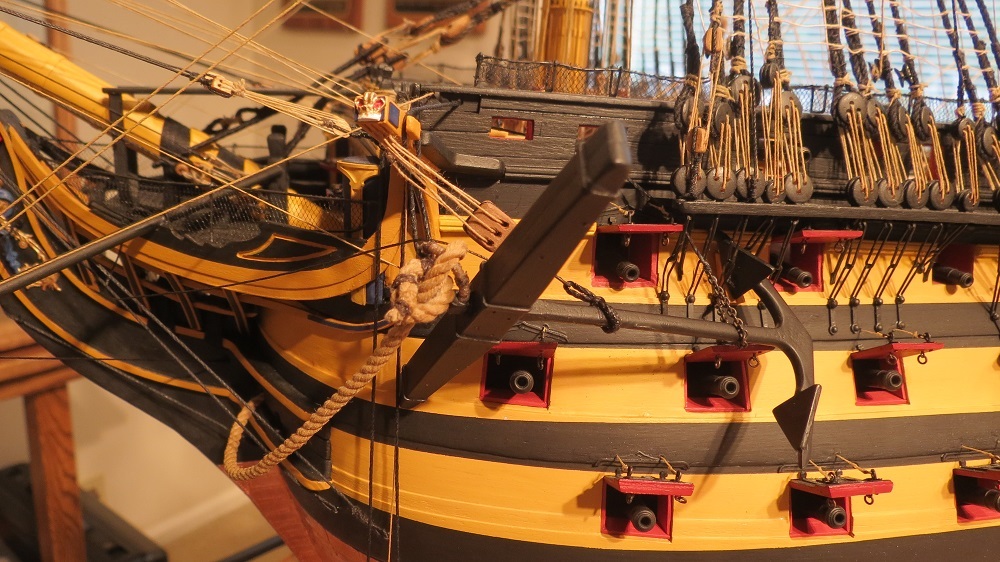
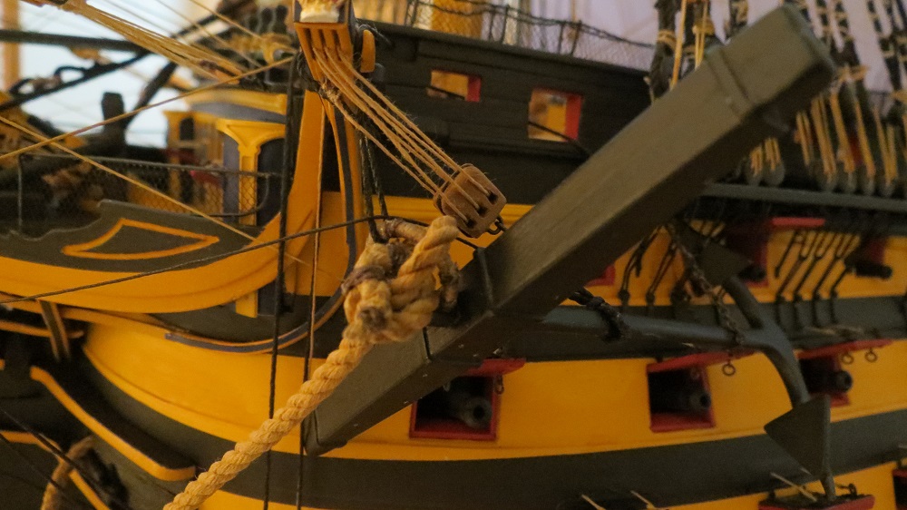
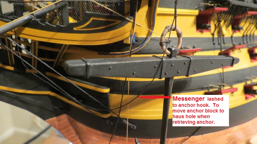
Continuing with the anchors after a diversion into display cases. While the port bower anchor is shown in the secured position, the starboard anchor is depicted in the process of being stowed. In the following photo, the anchor is catted (cathead tackle is two blocked, while showing the purpose of the cathead), the sling from the anchor ring has been place over the cathead, the lifting sling is seen at the inboard fluke and the chain and spliced line supports the shaft. To complete the process, the tackle from the cathead would be moved to a sling on the anchor shaft and the sling removed at the fluke.

Detail of the anchor ring sling.

Looking forward
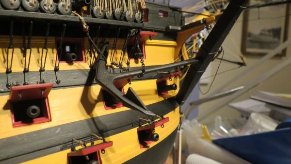
Cathead block and anchor hook. Messenger lashed to anchor hook.
Looking aft.

-
Thanks Glen and Joe.
Glen, you've made amazing progress on your Victory is what seems like a very short time.
Bill, We seem to agree, the model is fun and challenging while the grandkids are far more important and irreplaceable.
Cheers, Gil
-
Just converted to Firefox to upload drawings. A few pen sketches to explain case construction.
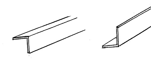
The brass "L" 3/8" each side by approximately 1/32" thick.
The back and side panels were glued together with aquarium silicone glue, then reinforced by gluing Brass "L" strips over the joint, hiding the glue joint.
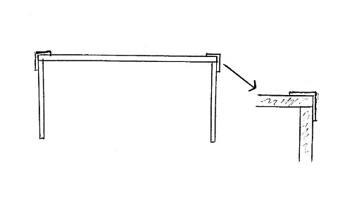
The front panel was finished with the brass "L" glued to the right and left borders. The brass L overlaps the side panels but was not glued to them.
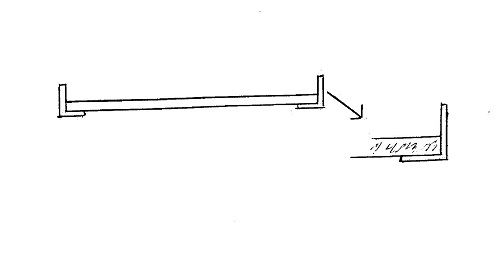
The top glass panel has brass L on all sides which overlaps all the other panels and holds the front panel in place.
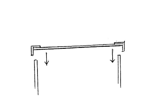
When the top panel is lifted at the front, the front panel is free to swing out and be removed, providing easy access to the model.
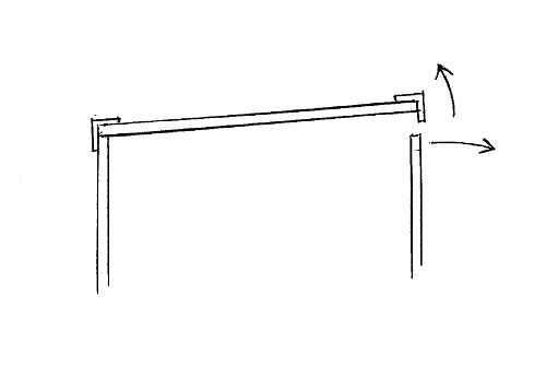
There are probably hundreds of ways to build a case. This worked for me. Cheers, Gil
-
Daniel, Always appreciate your visits.
Thanks David. I agree that some cases overshadow the model.
Jon, I enjoyed perusing your log, particularly the bow and served collars for the forestay and preventer. I'm requesting directions from our overworked moderators on posting a log on the Constitution.
Gerty, I also like your Willie L. Bennett. I think I mentioned before that a Chesapeake Skipjack may be my next project.
Jerry, Indeed, I had already checked your log. Good find on the table.
Mike, Like the idea of a mirror under toe model. I'll keep it mind when I get there.
Bill, Following is a description of how the case was put together. Probably more than you wanted to know.
The wood base has grooves created by a router. All the glass panels (back, sides and front) fit in these grooves.
The glass is 1/8" tempered glass. With active (hyperactive?) grandkids, tempering the glass avoids dangerous glass shards if broken.
The brass "L" shaped strips were 3/8" each side and approximately 1/32" thick. Tempering the glass creates some distortion, and 1/4" "L" was not enough to hide the distortion and cover the glue joints. The brass "L" was obtained through Michael Wall, American Marine Model Gallery ( wall@shipmodel.com ).
-
Lawrence, David, Bill and Jerry, Many thanks. I was out of town for the past several days and just returned.
David, the acrylic case with wood strips sounds like a great idea.
Bill, I can't imagine the Victory without a case. I think it would be a dust catcher, and little hands (grandchildren and great grandchildren) would eventually find their way into the rigging. I'll likely follow what I did for the Constitution.
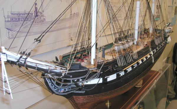
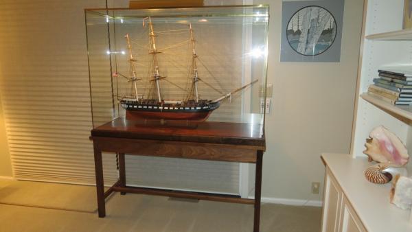
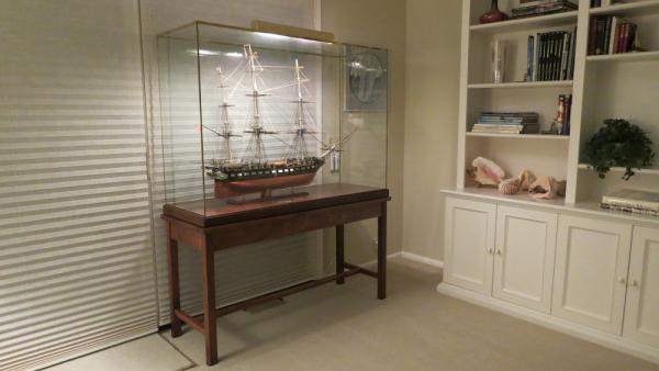
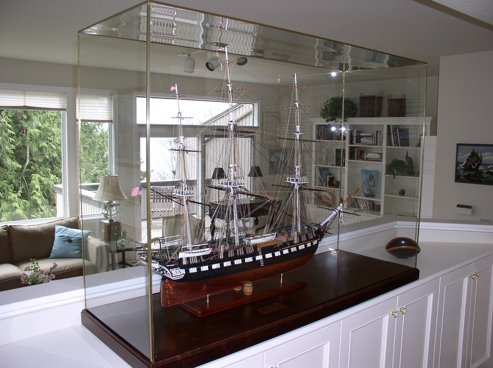
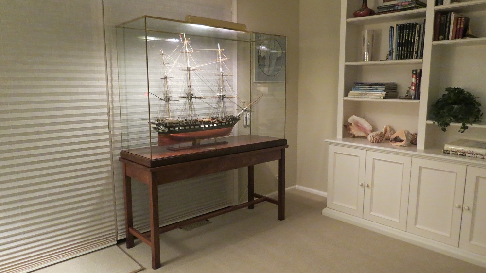
I made a case for the "USS Constitution" of glass (tempered, so that the glass would break into tiny bits if shattered). Brass trim was added and when the top front is lifted, the front glass sheet can be lifted out for easy access. And finally a table was made to fit the case. The Constitution however, was somewhat smaller than the Victory. It's a museum.
The model of the Constitution without a case.
Completion of the case.

And finally the supporting table.
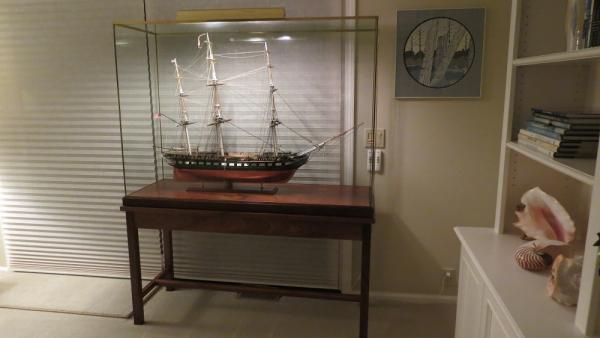
Cheers, Gil
-
-
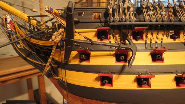
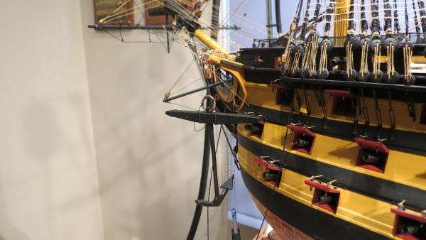
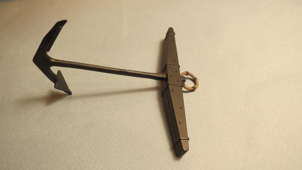
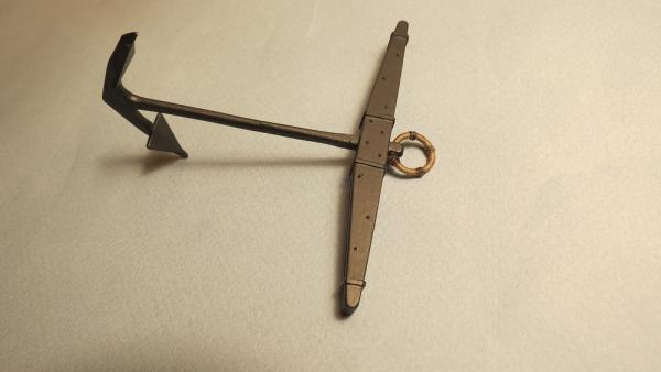
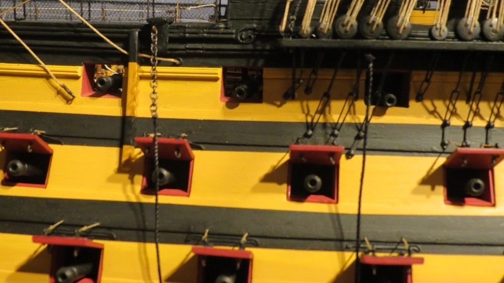
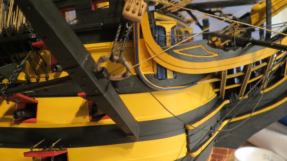
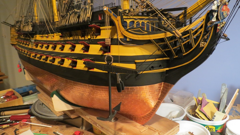
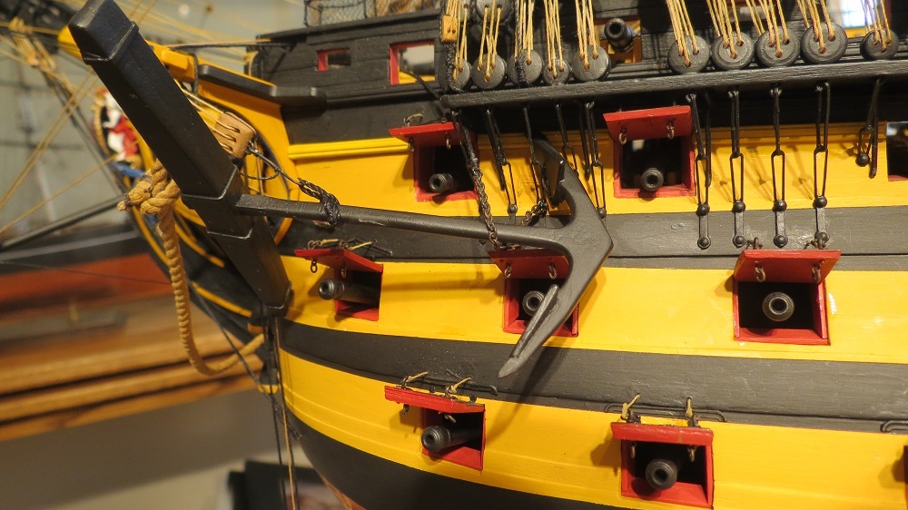
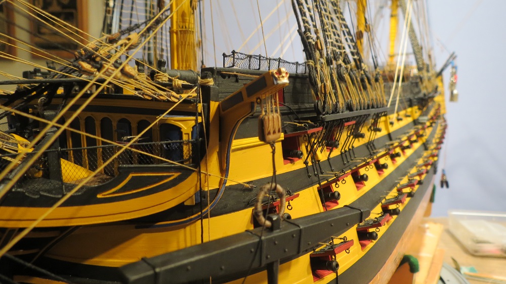
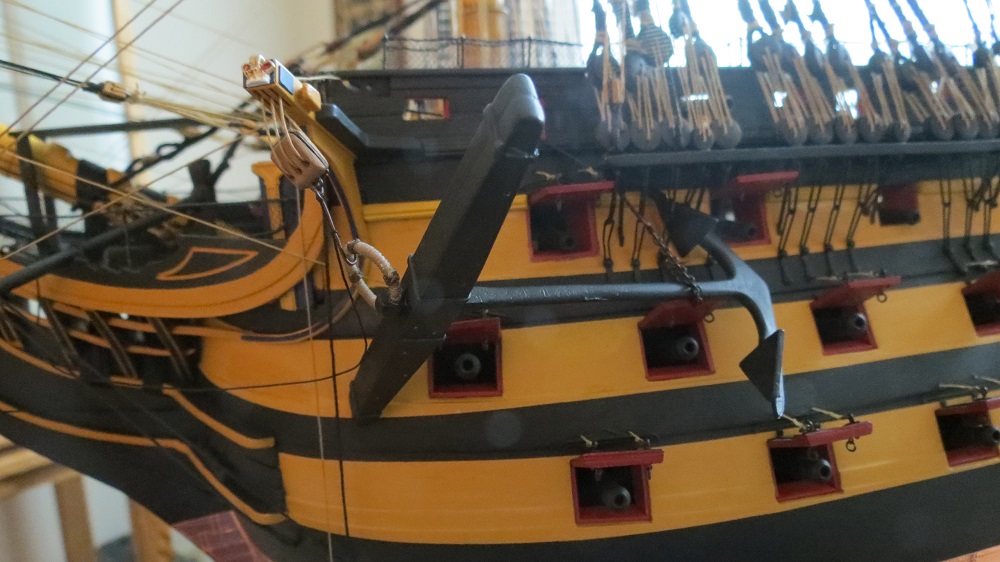
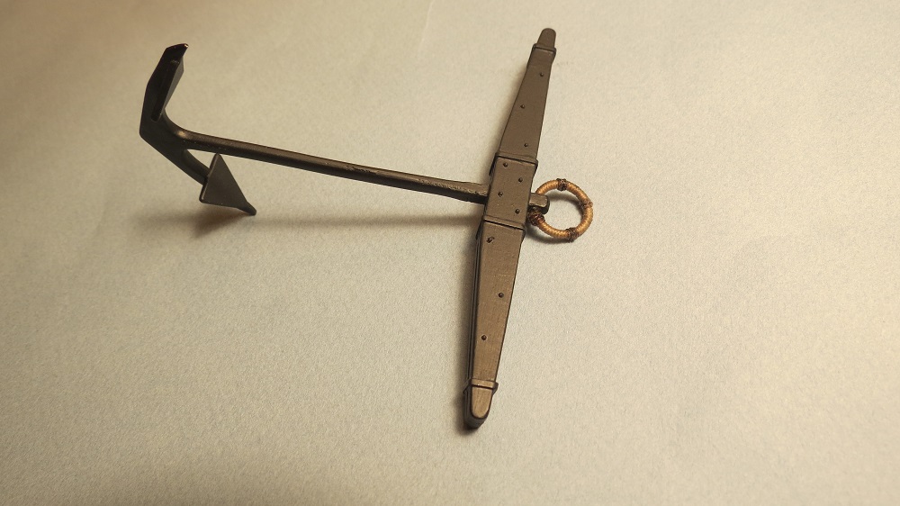
The Port Sheet Anchor in it's stowed position, held by chain and lanyard near the flukes and lashings at the stock.


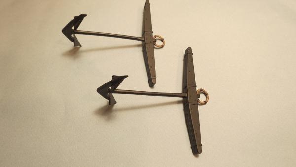
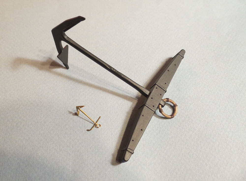
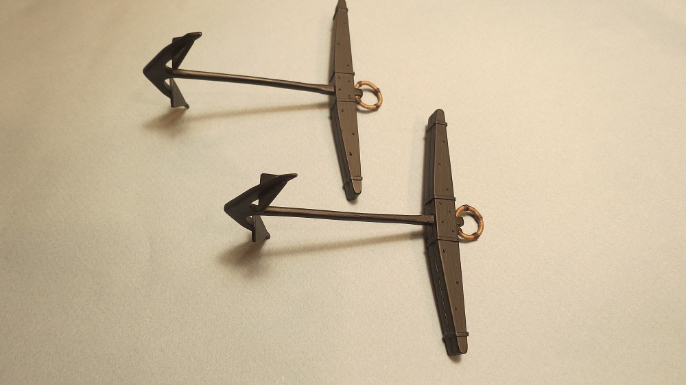
An interesting size comparison, between the Bower anchor (around 8000 lbs.+) and the small Kedge anchor that could be carried out by one of the ship's boats to kedge-off a shallow or help maneuver the ship.

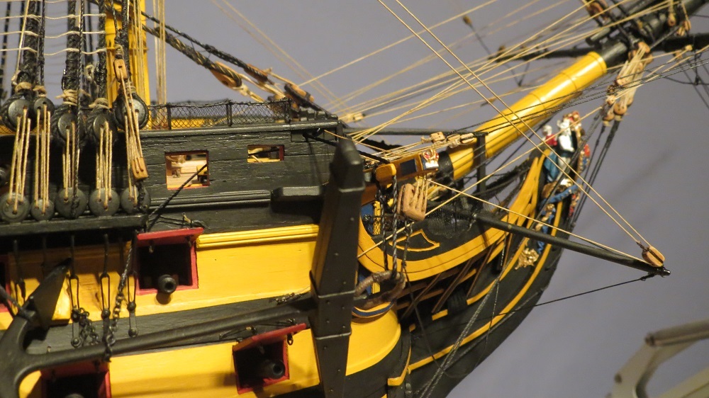
A better looking cathead block with simulated sheeves.
The Starboard Bower on the anchor hook

-
Oh, Edwin of Port Alberni, you are very kind. With any luck, we'll arrive someday at Port Alberni by car? or boat? and share a wee dram. I hope the log is helpful.
David, Many thanks. Only Daniel can give us a crew slacking the anchor cable with another crew hoisting the anchor to the cathead. I must rely on our imagination. I find that the little projects take on a life of their own and are more fun. However, it does slow down the build. Thank goodness there is no performance clause attached to the build.
Cheers, Gil
-
David, Appreciate your comments. I've missed the updates on the Bluenose. I'll try to connect with the PSSM next month. Gil
-
-
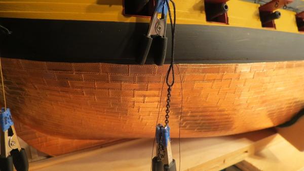
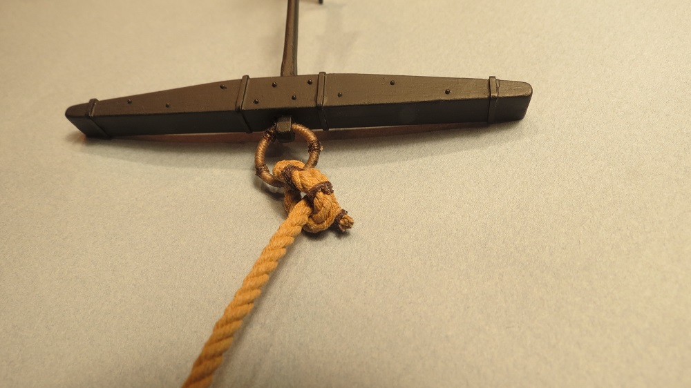
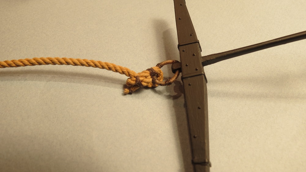
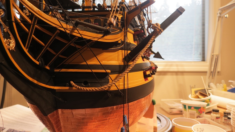
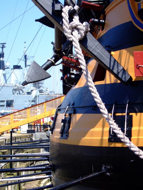
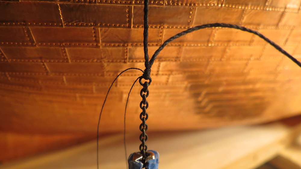
Fastening the cable to the anchor.

Looking at the real ship, I had difficulty interpreting the fastening of the cable to the anchor. It didn't look secure, but then a 9" diameter anchor cable doesn't lend itself to using an anchor hitch. My other references weren't much clearer. Looking at my printed (photocopied reprint) of David Steel, the quality of the illustration was too poor to interpret, however, the web site version available through the Historic Naval Ship Association (Steel, The Elements and Practice of Rigging and Seamanship, Vol. II, p. 304) was much better.
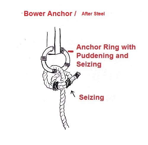
A simple scetch showing the fastening of the Bower anchor according to Steel.

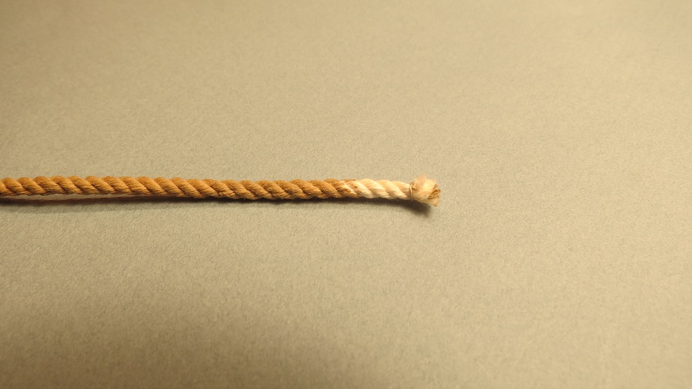
Staining the anchor cable to simulate hemp/Manilla (Minwax water based English Oak)
Isolated view of fastening.

The next post completes the Bower anchor.
-
Are we having fun yet? Thanks to you all for your comments. Alister, your "Fly" is a work of art. I enjoyed going through your log. Grant, Many thanks. Glad you still have one foot in the "kit" world. David and Jerry. Let's see. If we sold twenty copies at a two dollar royalty, we'd be wealthy?????? Mike, Great progress on your "Unicorn" (AKA "Lyme"). Daniel and Popeye, always a pleasure to see your interest. And Kevin, the block is glued to the ship. If it were fixed to the anchor, I'd be afraid it would foul the chain plates when positioning the anchor. Cheers, Gil
-
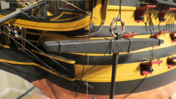
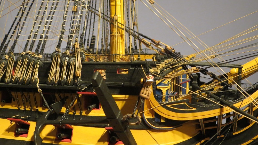
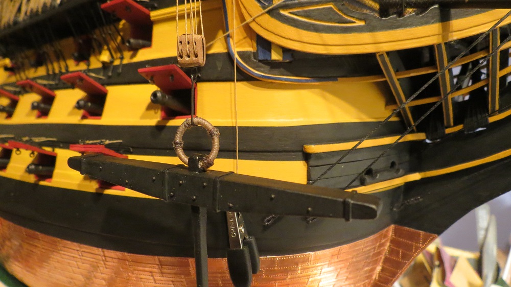
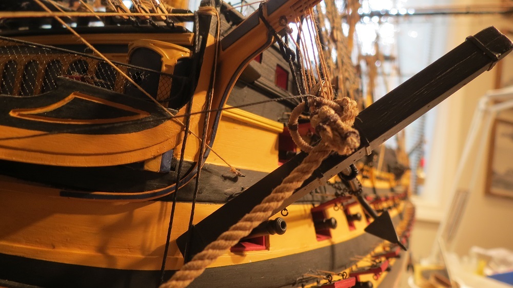
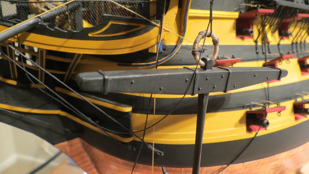
Final steps in stowing the anchor.
An eye splice for lashing the anchor ring to the cat head.
Anchor ring lashed to the cathead.
Cathead tackle shifted to a sling on the anchor shaft.
Anchor in the stowed position.

Next up. Fastening the cable to the anchor.
Gil
- AON, fnkershner, gieb8688 and 13 others
-
16
-
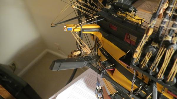
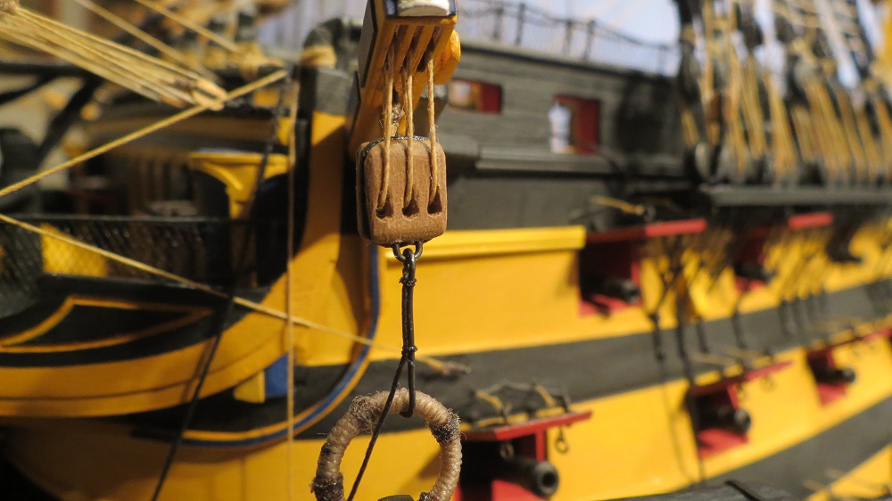
Anchor tackle at the cathead with the anchor ring in the hook. The line seized to the hook is the messenger to bring the block to the haus hole for retrieving the anchor.
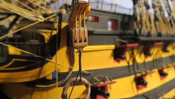

Anchor ring hooked with the messenger line seized to hook.

Stowing the anchor. Chain supporting the shaft. Anchor ring still supported by the cathead tackle hook.
Another post follows
- fnkershner, augie, GuntherMT and 9 others
-
12
-
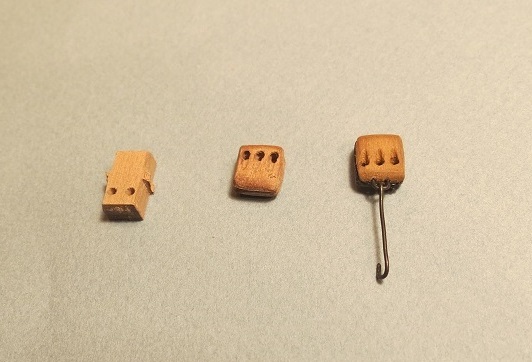
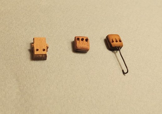
Attaching the anchors.
From left to right, a double block as supplied, a triple block shaped and a tripple block stained, stropped, with steel becket and anchor hook. I should have added holes in the upper part of the block to look more natural. On the starboard block, (the display side) those holes and carved slots will be added.
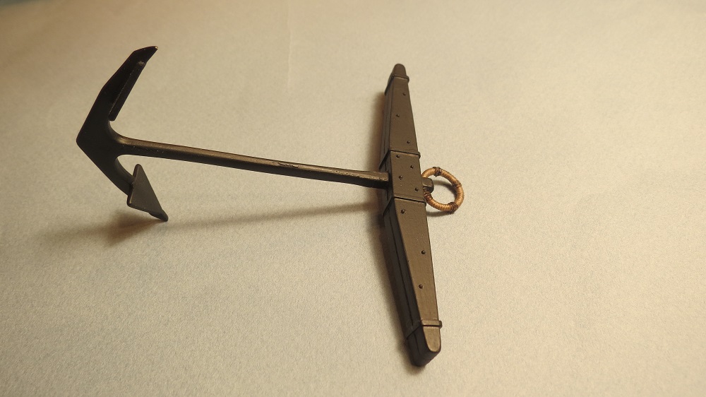
Preparing the anchors. These were previously covered in Section 13, page 3, post #39. I plan to display the port best bower anchor in the stowed position (after McKay), while the starboard anchor will be suspended by the anchor block from the cathead. This conveys even to the novice, the function of the cathead.
Creating an eye splice from a line to chain, to support the stowed anchor.


Continued in next post


HMS Victory by gil middleton - FINISHED - Caldercraft - 1:72
in - Kit build logs for subjects built from 1751 - 1800
Posted
Hi Harvey, I agree, the the tape doesn't do much to protect soft wood. The main reason I use it is to hold small threads when tying seizing, knots or whatever needs holding. Without the tape, threads seem to pull through the clips. Just regular 3M masking tape (the rough type) most of which have lasted through the six years with Victory. Nice to hear from you. Cheers, Gil