catopower
-
Posts
1,901 -
Joined
-
Last visited
Content Type
Profiles
Forums
Gallery
Events
Everything posted by catopower
-
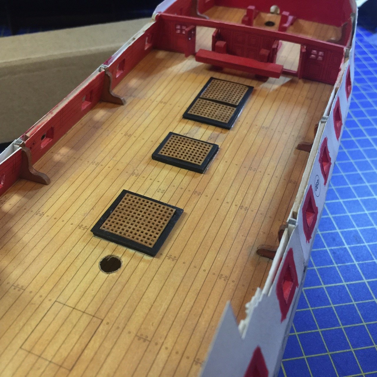
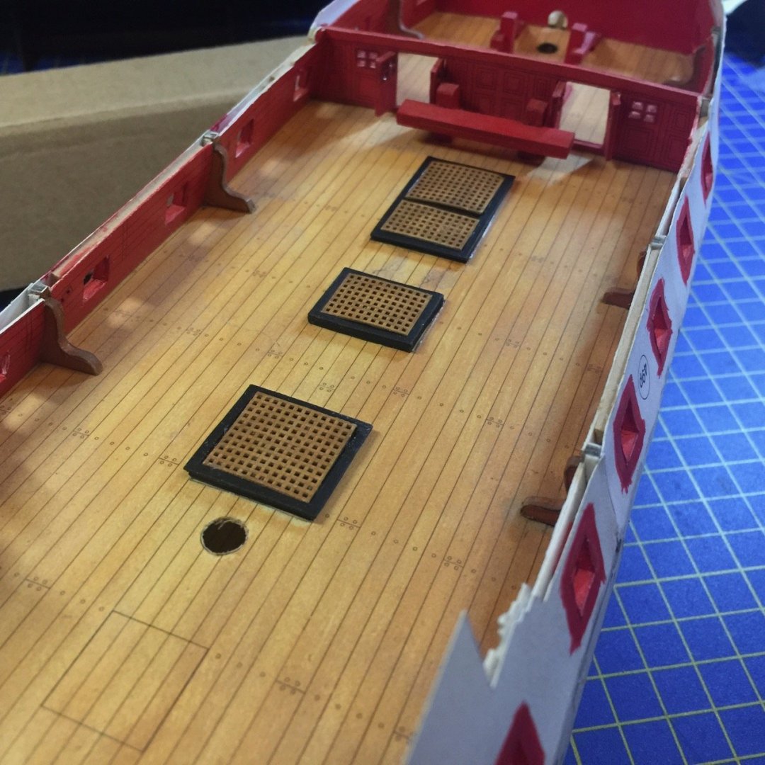
 And since it was clear that I had some parts sitting around that were pretty much ready to onto the model, I went ahead and added the hatch coamings and gratings. The gratings were from the GPM laser-cut detail set. These have all the holes nicely cut, but oddly enough, there was still a paper backing – the laser didn't cut all the way through the holes. I opened these up by slicing off the back of the gratings. Now, the holes go all the way through. Not that you can see through the ones on this deck. Don't get too excited about the progress. I was just looking over the model and found something I could do easily. I'll get back to the other projects I need to finish now, but this was a fun distraction... Clare
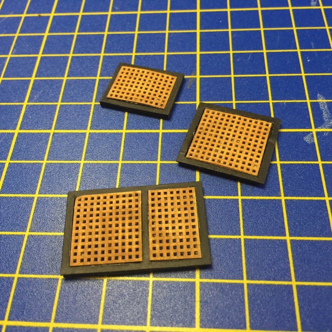
-
Chuck, I saw the order come through at Ages of Sail, but didn't make the connection that it was you! Didn't it get dropped off this afternoon? Clare
- 175 replies
-
- 3
-

-
- hanse kogge
- shipyard
- (and 1 more)
-
Hi Keith, great series of posts on your HMS Terror build. You've been doing a terrific job. Looking forward to watching your progress. Clare
-
While I've been focussing on Shipyard's Hanse Kogge laser-cut kit and on finishing my Kitamaebune kit, plus have a few things in the pipeline I need to wrap up, I keep seeing this project sitting on the shelf. The laser-cut kits are much easier, but still, this model seems to still be waiting patiently. I got tripped up when I started working on the furniture for the great cabin. Not sure what to do about that as it's stuff that will be very difficult to see on the completed model. But, I will be looking at it again. Just to tease those who miss this project. The beauty of the Hanse Kogge kit is tempting me to take on the laser-cut HMS Wolf or the much more expensive 1/72-scale HMS Mercury kit when the cog is done. Just food for thought...
-
Thanks, VTHokiEE. I mostly have been using contact cement applied to both surfaces to be glued together. But, unlike the usual use of this type of cement, I put the pieces together right away. Otherwise, once the parts are together, they're stuck for good. Of course, this is the reason I had the slippage that needed repair. I just wasn't careful enough to make sure the glue had set well enough before moving on. Hi Chuck, if you're talking scratch building, then sure, a "multimedia" model would be fine. There are some beautiful examples of that here on MSW. But, with these Shipyard laser-cut kits, I don't see the point, at least as far as these kits go, since the parts are already so nicely made. Now, the paper kits made by Shipyard feature a similar laser-cut card stock frame, and since planks aren't pre-cut for you in most of the kits, I could see trying to plank them using wood veneer. They also published what they called "Super Modellar Plans", which is a set of plans, plus laser-cut frame and basic hull covering. You're expected to build the rest of the model up from there, including the planking. I've thought one of these might be nice planked with veneer. I have one of these, the Spanish frigate Santa Leocadia. The frames are assembled, but I haven't decided if I want to do anything with it yet. On this latter set, I should point out that they don't produce or sell these any more. However, I have seen them on a Polish card model shop, which I have ordered from in the past, gpm.pl.
- 175 replies
-
- 5
-
-
- hanse kogge
- shipyard
- (and 1 more)
-
Good choice. Looking forward to seeing you get started on it! I started the Phantom as my very first wooden ship model. I was building plastic ship model at the time. But, I enjoyed working in wood so much, I never went back to the plastic kit. That was close to 30 years ago (wow). Good luck with your build!
-
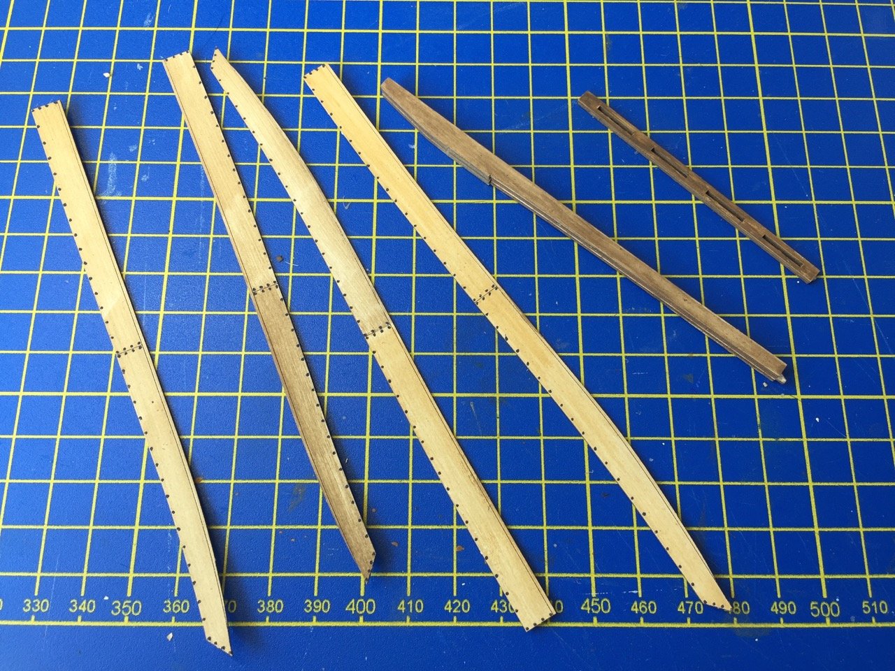
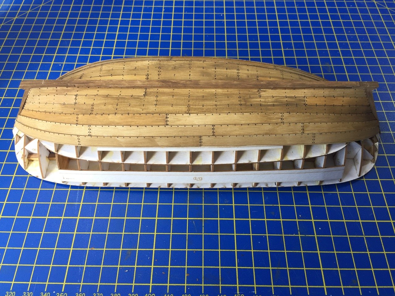
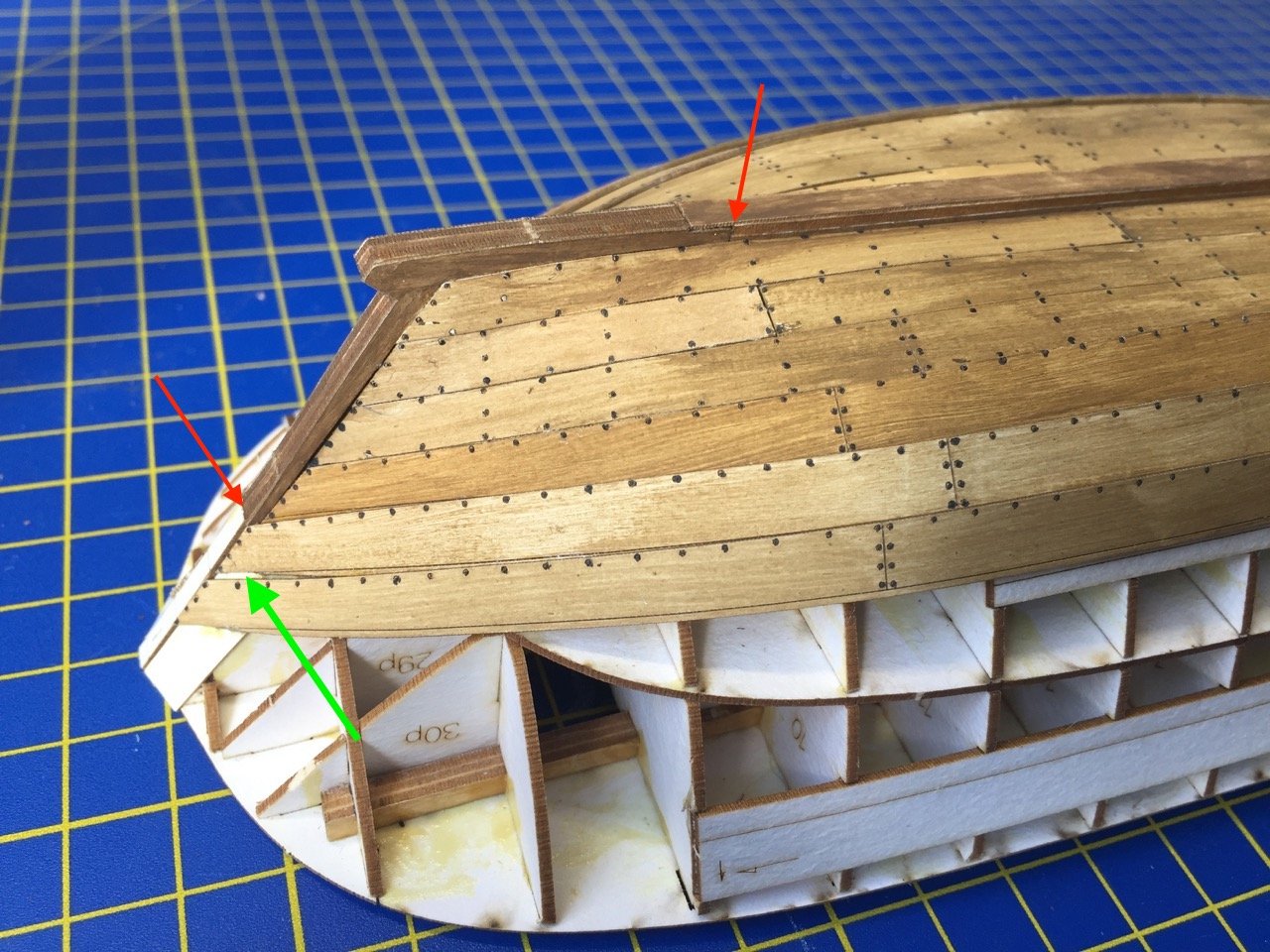
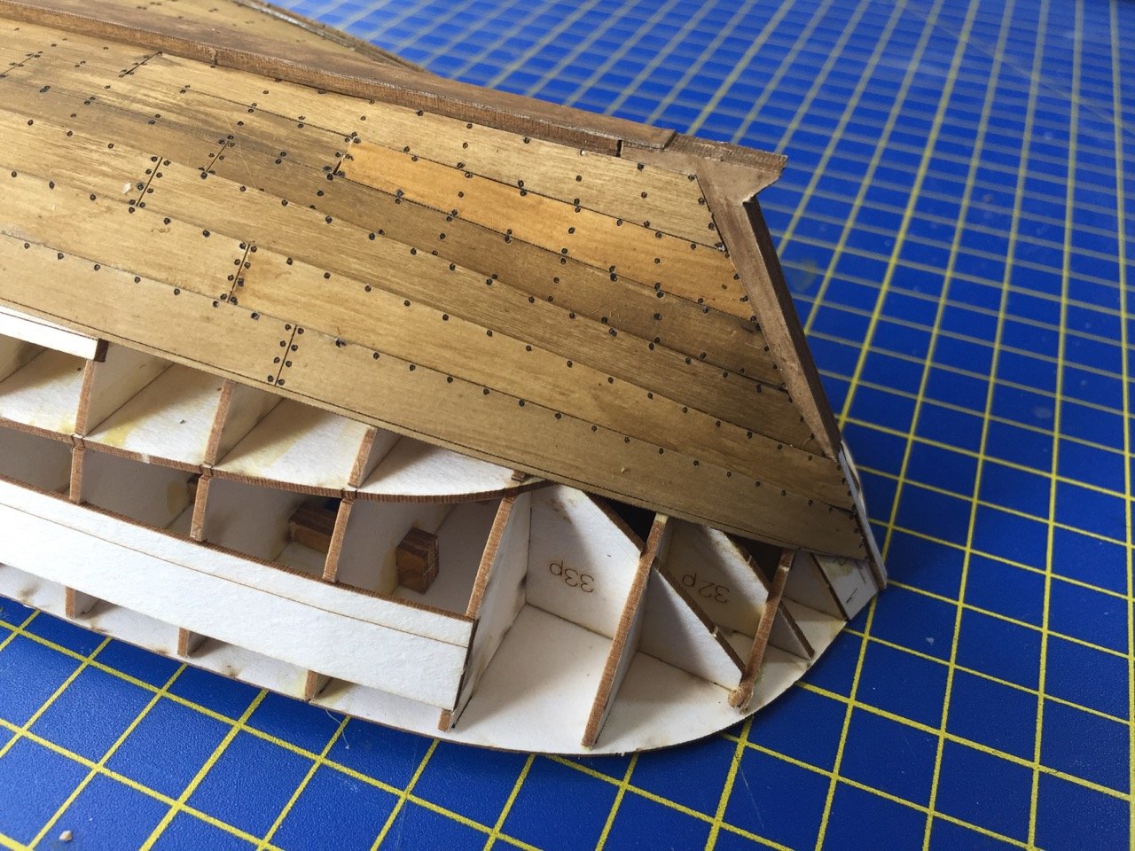
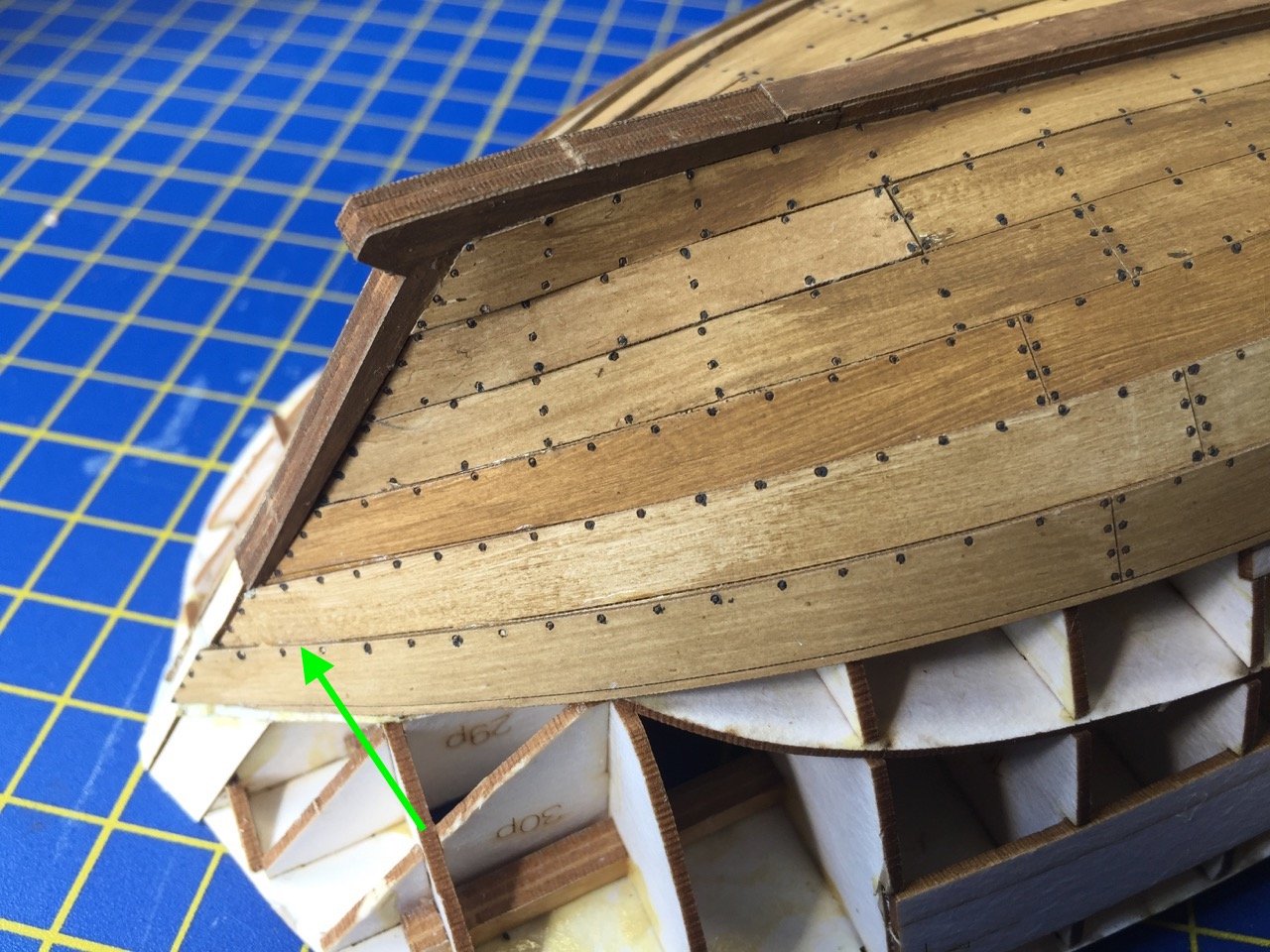
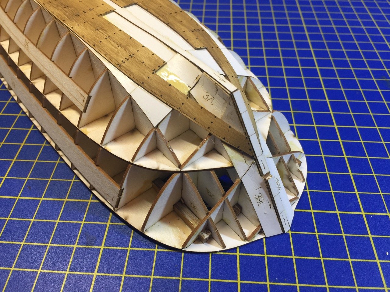
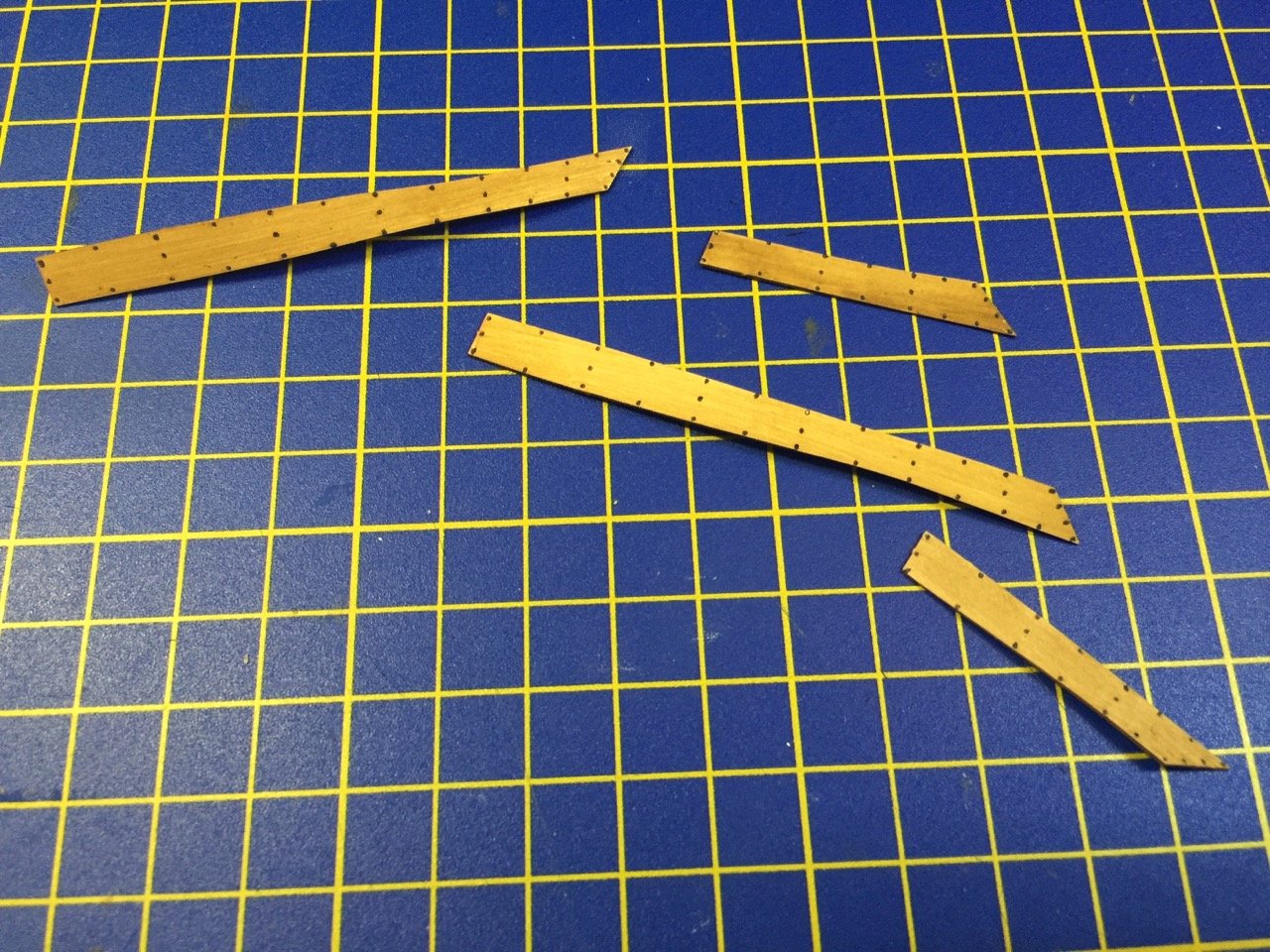
Another short update on the Hanse Kogge. I've been working on the lapstrake planking and reached the point where it was time to add the keel. Seems like it's not much work done. But, in fact, the keel is made up of the main keel and the knees, if that's the proper term, for the base of the stem and stern posts. Plus, the keel is made up of three separate layers that have to be glued together and each of the knees are made up of five layers. The middle layer of each of the knees is slightly different than the other layers, so that together, they create a notch that later pieces will fit into. This seemed kind of clever to me. I pre-painted the necessary pieces and glued them up. Later, I touched up the paint a bit and then glued them to the hull. I also did the same with the keel at the same time, as I wanted to make sure everything fit correctly and that there were no gaps between the parts. I always find it confusing and have to double check which direction the ship is facing. Even here, as I'm writing, I have to stop and check. The bow is on the left in the photo above. Today I discovered that a couple plank pieces I installed the other day had slipped out of place before the glue set fully. As I've been using contact cement, this required a bit of very careful surgery. It's rather appropriate that I have a scalped on hand for this model. In the following photo, I marked the ends of the knee at the bow with red arrows. The planking slip-up is clear, but I marked it with a big fat green arrow. I repaired this by carefully slipping the scalpel blade under the plank. Of course, what's mostly going on is that I'm cutting into the plank piece itself, and cutting away a thin slice of the back side, which is glued into place. But, this allowed me to reposition the plank, to create the proper overlap. I reglued the piece into place, but now the plank extends a little too far out, as you'll see in the next photo. The plank position has been fixed, and there is no longer an unsightly gap at the bow. I'm not too sure this will affect the later planking, but it seems like it's positioned correctly with the registration marks printed on the stem end piece. Looks like I'll have to trim off the very end though, which also means that I'll have to repaint the nails without the benefit of the little laser-etched circles. I think it will be alright though. The stern knee placement went fine and there are no signs of any planking issues there. Finally, as you can see below, the pieces for the next planking strake are ready for installation. Those two piece to the right are stem and stern post pieces that will go on soon. One other thing I discovered with my model work that I corrected before I wrote this post. I managed to forget to paint the nail heads of the previously attached planks. I took care of those first thing. Must have been tired!
- 175 replies
-
- 14
-
-
- hanse kogge
- shipyard
- (and 1 more)
-
Hello Bolin, Nice progress you are making on your model! One of the early models I built was the Billing Boats Bluenose II, which was one that was built in two halves. I found that the system works quite nicely. I like the way you're resolved some of the issues with bending the plywood. I haven't looked at the other build logs, but I wonder if they have always provided plywood. It's my recollection that a different type of single ply wood used to used more often in their kits. I think it may have to do with where the kits are produced and what materials are readily available. Anyway, looking forward to following your progress here. Clare
- 83 replies
-
- 1
-
-
- finished
- billing boats
- (and 1 more)
-
Ages of Sail is now carrying the range of Master Korabel kits. Though, for now, the Brig Phoenix and Schooner Polotsk are available only in the higher-end "Plus Edition", and the Tender Avos is only available in the high-end "Special Edition" version with the pear wood planking. Looking forward to getting my hands on one of these lovely kits! Clare
- 216 replies
-
- 7
-
-
- masterkorabel
- ships
- (and 3 more)
-
I'd be careful about the effects of alcohol on paper. The acrylic paints provided work very well. But, as you say, you can always try out different things, given the extra time available. Clare
- 175 replies
-
- 4
-
-
- hanse kogge
- shipyard
- (and 1 more)
-
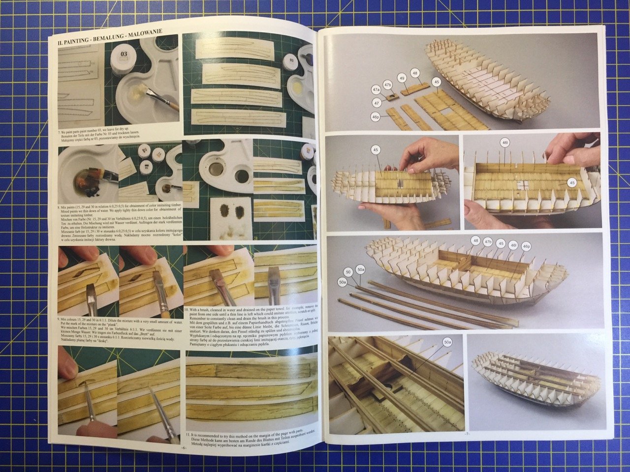
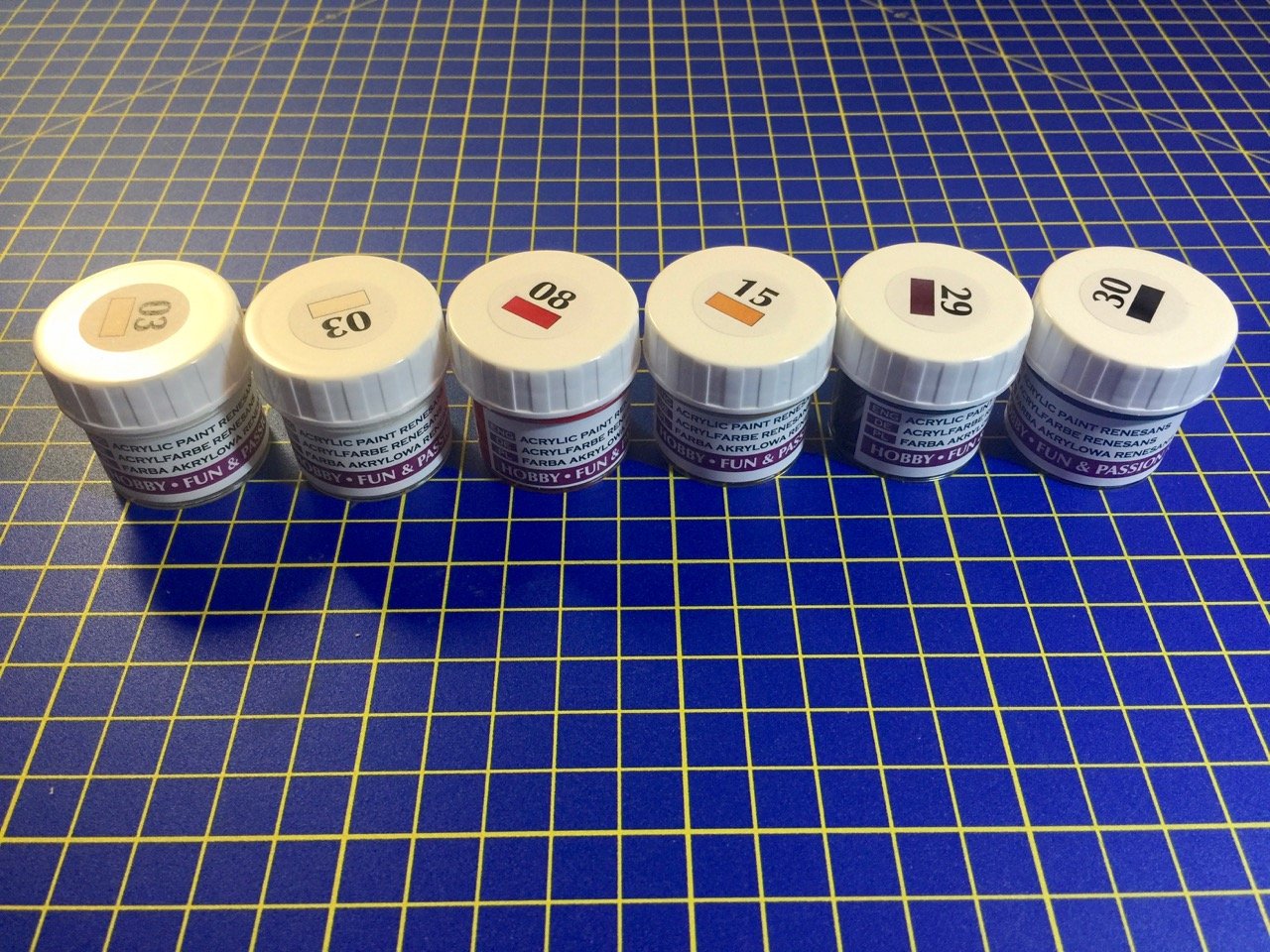
Thank you Druxey. I'm just hoping it will continue that way. Christian, the instructions have you pre-paint everything with color number 03, which is Naples Yellow. I found that it worked best to thin it down, though I don't have a specific formula. It's just thin enough so that it goes on somewhat transparent, so you can continue to see the laser-etched details through the paint. This needs to dry thoroughly before you paint over with the wood colored mixture. I recommend letting it dry over night. This makes a kind of a primer coat, so that the wood colored mixture can go on, well thinned down, without beading on the surface of the paper. The instructions then have you mix paints in a given ratio. The paint colors are 15, 29, and 30, which is Raw Sienna, Burnt Umber, and Black, and the mixture is given as 6:0.25:0.5. To make it simpler, I multiplied it all by 4, so it's 24:1:2. I pre-mixed this into a mini paint pot - the kind that comes in a strip and has an attached lid. These are only something like 0.1 or 0.2 oz each. But, it doesn't take that much paint to cover the model. I filled on up with paint mixture and then I mixed up a couple with a smaller amounts of paint using slight variations of the main ratio. Most parts are painted with the main ratio, while others are painted with the alternate ratio, so there is a very slight variation in colors of the wood. I didn't try to use the wood grain technique they showed in the book. It didn't seem necessary to me at this scale. When I applied the wood colored paint, I applied it very well thinned down, so it goes on a kind of a wash. You need to practice on some of the scrap paper in the kit. The amount of thinning really affects the application of color. The mixture looks dark tan, but thinned down, the wood looks more of a golden brown. You don't want to re-brush over an area too much, or you'll start to strip away the undercoat you painted earlier. If the color is too light, you can go back in another 24 hours and go over it again. You can also do this to add a little color variation across the parts. Of course, you'll want the brush strokes to go along the direction of the imagined wood grain. The most difficult part is probably that some parts simulate many planks all together. You can paint the whole thing at one time and then go back later and apply a thin wash to some of the planks to make them slightly darker, indicating a natural variation in wood sources. Clare
- 175 replies
-
- 8
-
-
- hanse kogge
- shipyard
- (and 1 more)
-
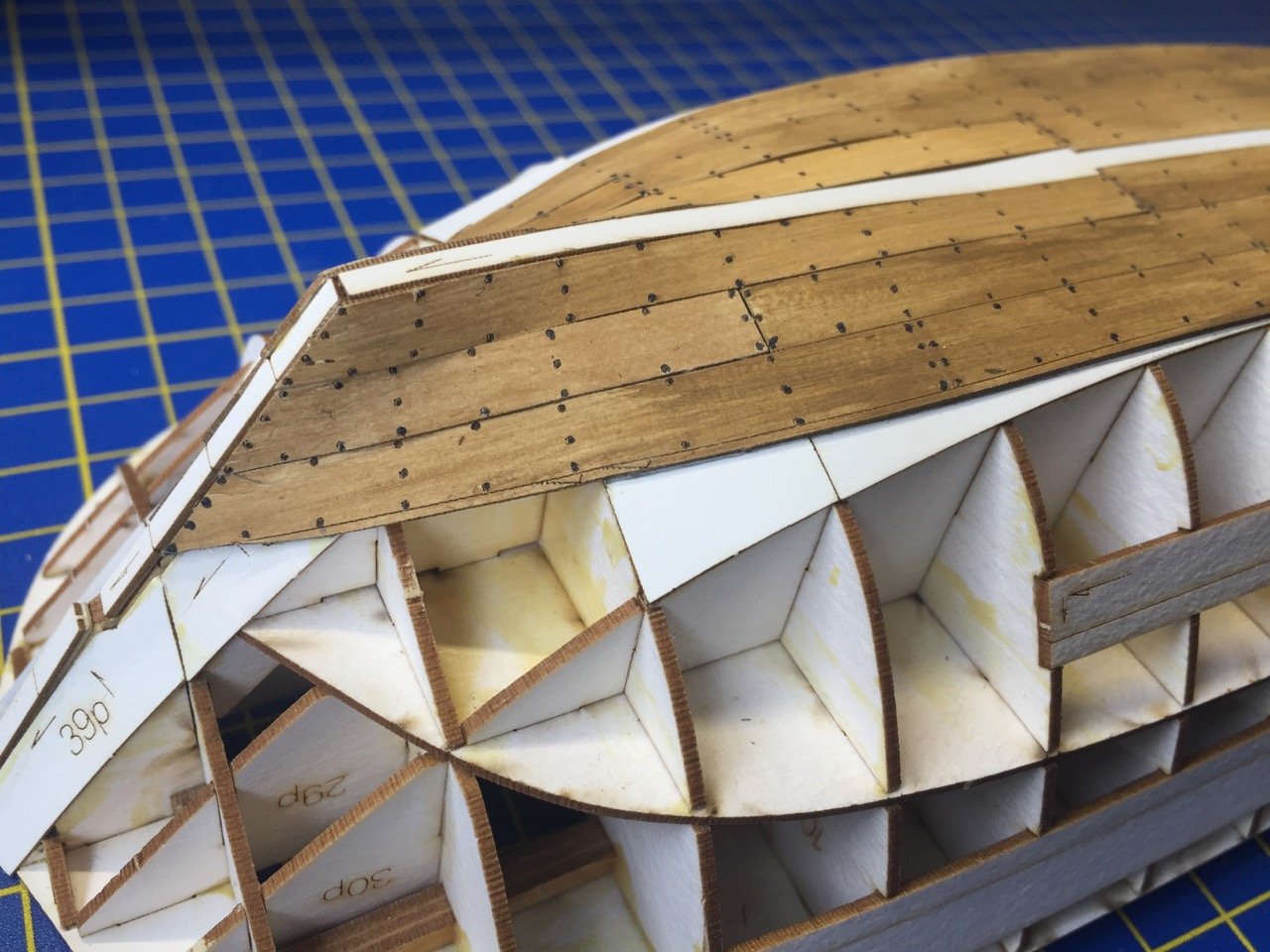
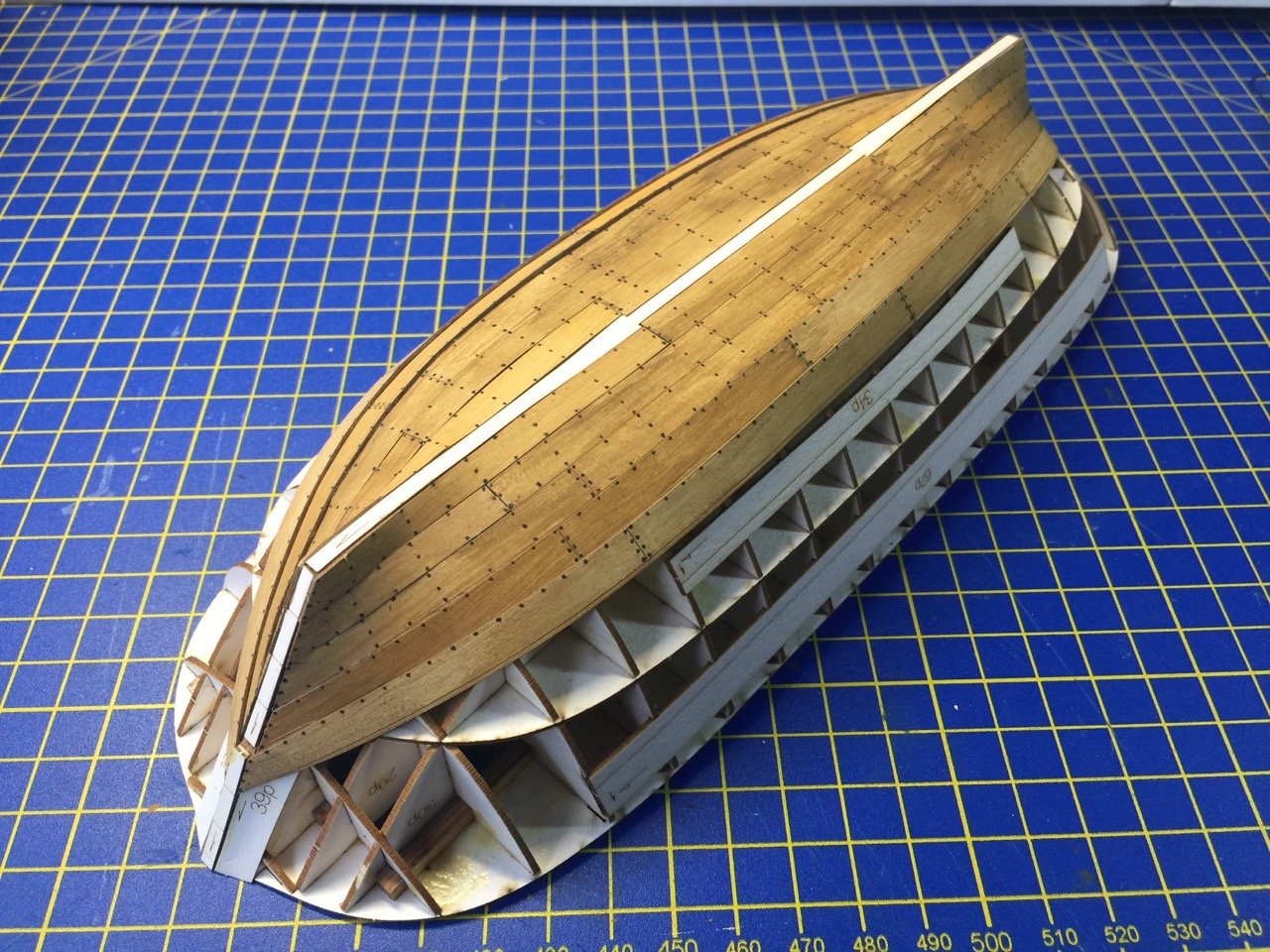
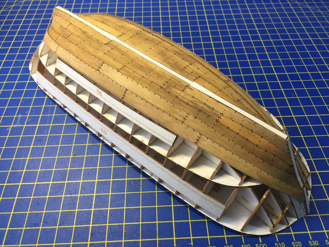
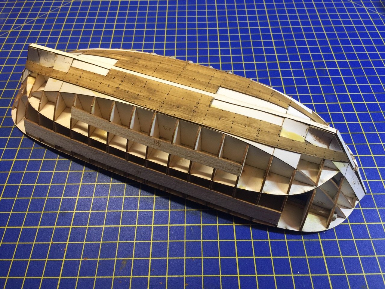
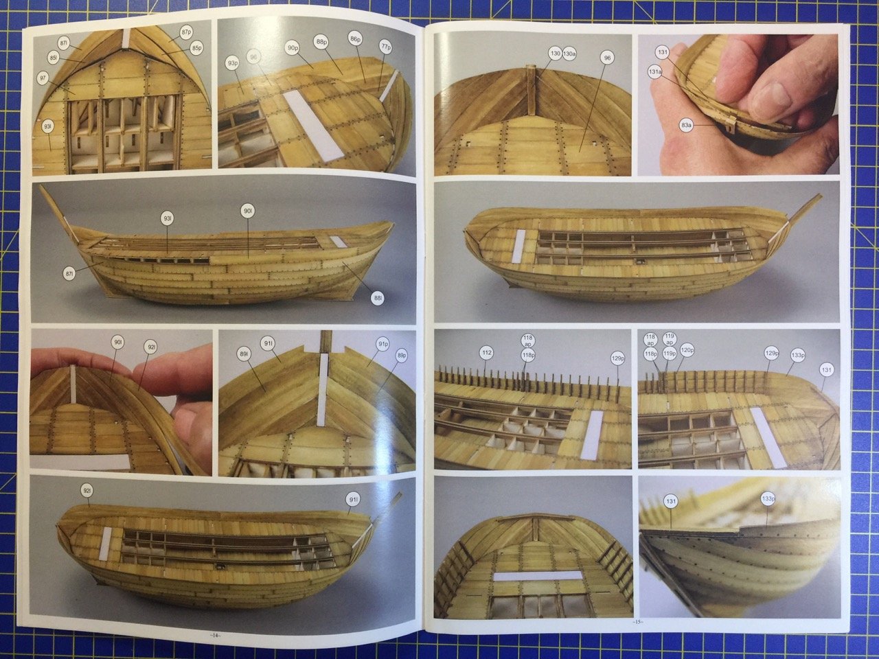
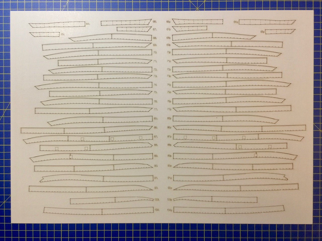
I finished page 11 of the instructions with the completion of the lower planking. But, I found that there is a slight disconnect in the instructions. Here's where I am so far on the planking. Planking has been going quite well. The planks are very well shaped, and go into place very easily, laying right where they need to go. The planks are marked with a thin black line as a guide for laying the next planking strake in clinker fashion. The disconnect I'm describing is simply that instructions don't show the rest of the hull planking that needs to go on in between pages 11 and 12. The last planks I added here are planks 70 and 71, which make up this last strake. It appears that planks 72 through 74 make up the next two strakes, and these need to be added before continuing to the next page of instructions. Not a big deal, but it would have been nice if this were clearer in the instructions. Clare
- 175 replies
-
- 14
-
-
- hanse kogge
- shipyard
- (and 1 more)
-
kit review 1/72 Wütender Hund by Shipyard - Hanseatic Cog
catopower replied to ccoyle's topic in REVIEWS: Model kits
Chris, thanks for the plug about my build. Very nice kit review! It looks to me like the Wütender Hund kit is nearly identical to the card model version. Perhaps it will entice those people unsure about building from card stock to try a Shipyard kit. Chuck, regarding the planks, a couple minutes on the Internet should answer the questions about the planking: https://en.wikipedia.org/wiki/Bremen_cog#/media/File:Bremen_Hansekogge_RolandvonBremen.JPG https://en.wikipedia.org/wiki/Bremen_cog#/media/File:Hansekogge_Bremerhaven_uf.jpg The first are the remains of the Bremen Cog excavated in 1962, the second is a modern reconstruction. I know Shipyard's Hanse Kogge - Bremen 1380 that I'm currently building is based on this reconstruction. I'm not sure of the basis for the Wütender Hund kits, but the plank fitting is similar. I don't know enough about cogs, but their clinking planking and framing seems very much like the Viking longships, in which the overlapping hull planking is nailed together and frames added afterwards – correct me if I'm wrong. Chris, when are you starting??? I know, you answered this question before, but I have to bug you as this is a pretty neat looking kit. Clare -
Thank you CDW, Druxey. Druxey, it probably would be easier with a marker. I'm just in such a painting mode that I didn't even stop to think about that. Never heard of a "Pigma" marker before, so I had to look that up too. I'm going to have to try that out. Thanks!
- 175 replies
-
- 4
-
-
- hanse kogge
- shipyard
- (and 1 more)
-
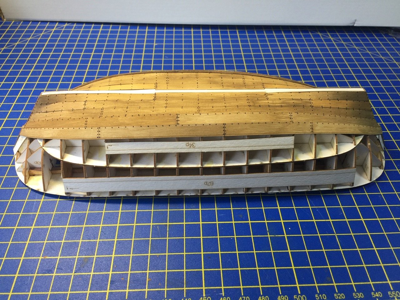
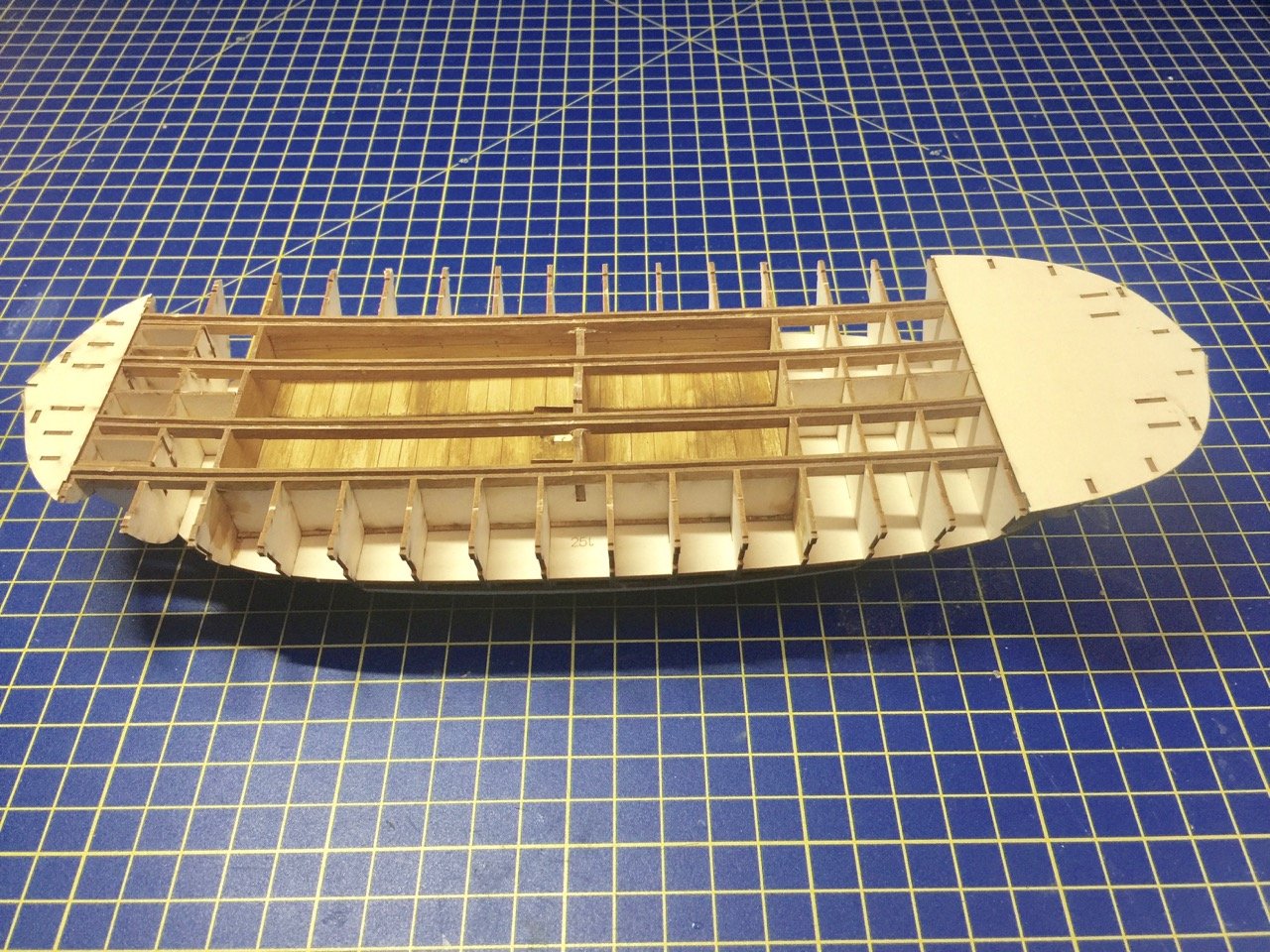
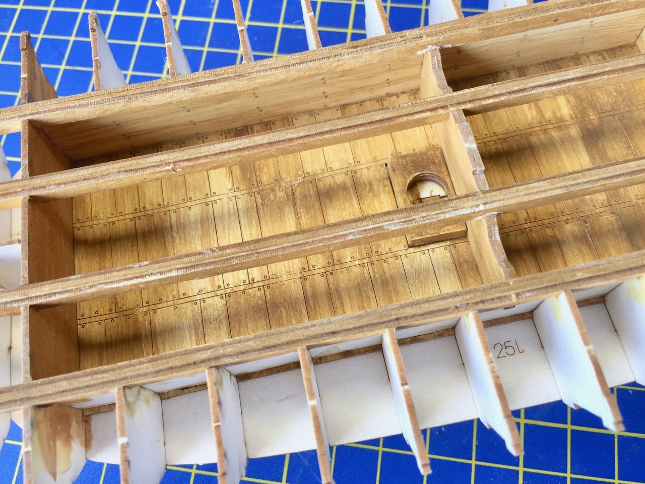
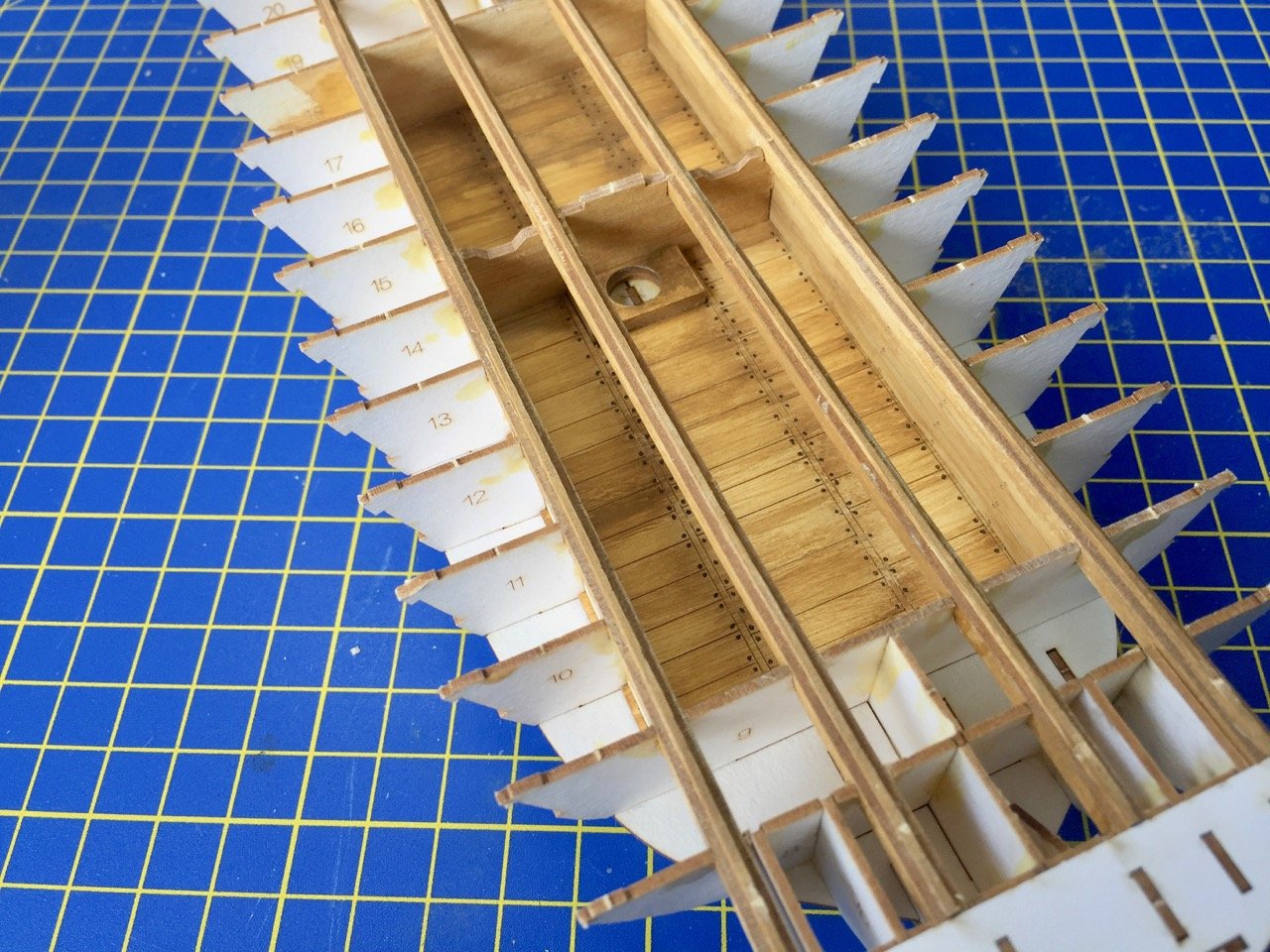
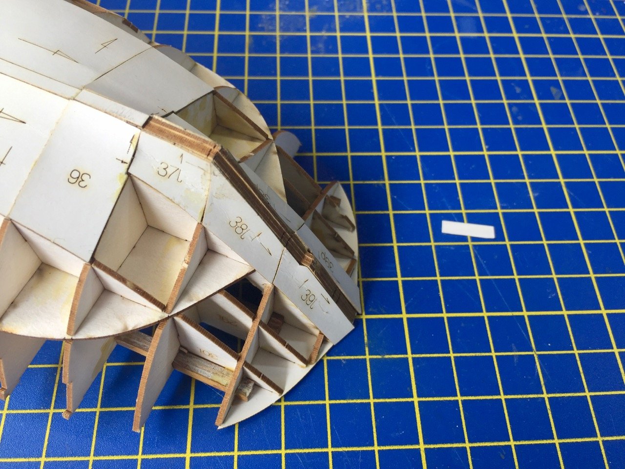
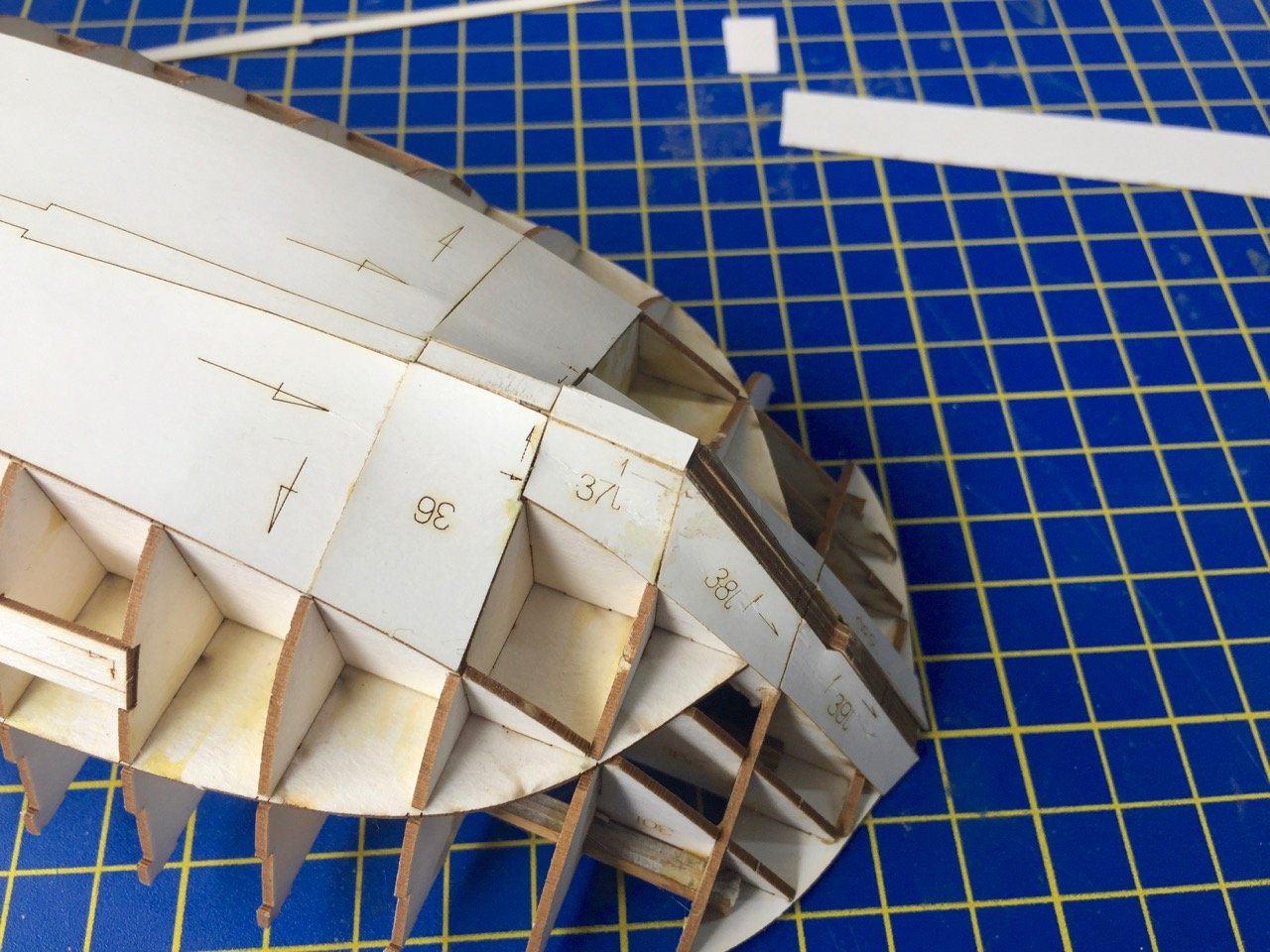
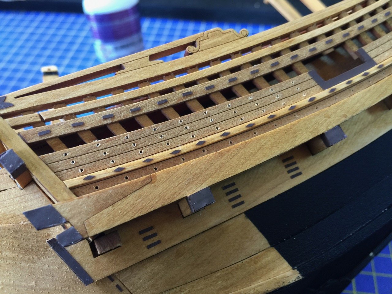
I managed to make some time to work on the Bremen Cog this week. On other Shipyard kits, the frames are all covered with a first layer of "planking", what a lot of people call "skin". On this kit, only the lower part of the hull is covered. On the upper part, there are only stiffeners. I already test fit the internal floor and walls and assembled the longitudinal beams that will support the main deck. Not sure why so much interior is present. There is only one small hath on deck, and even if it's left open, you wouldn't be able to see more than just the area around the mast. I actually took this photo before adding the hull stiffeners or lower hull covering. I started painting using the paints included in the kit in the mixture described in the instructions. It's actually something of a two step process, as you first have to paint the parts with the light colored paint. It's simply labeled 03 on the jar, but the manufacturer, Renesans, says it's Naples Yellow. I found that it works best to thin it down and then paint the paper with it and let it dry for at least 24 hours. I didn't do such a great job with the paint job on the interior. It was my test/practice area and isn't going to be very visible anyone, so I wasn't too worried about it. In the instructions, the builder clearly painted all the laser-etched nail heads. I didn't think I was going to be able to do these, but I ended up giving it a shot later on. Only thing was that I didn't decide to paint the nail heads until I had completed the interior area. In the last photo, you can see that the nail heads turned out okay. At least I thought so. It took a little time, but wasn't nearly as difficult as I thought it would be. I just had to use a very fine brush and dab. Here the first mistake I made on this model. There are tabs along the edge of parts 37, 38, and 39. It wasn't very clear to me, but these tabs are supposed to be glued to the outside of the inner keel piece. I needed to correct this by adding just a little thickness to the edge of the inner keel piece, so i cut strips of excess card stock and glued them into place. The photos show just the first strip. Finally, here are some shots of the first of the planking. That puts me somewhere on page 11 of the instructions. A long ways to go, but I ran across someone else's build log on a paper modeler's forum and was inspired by their build and the fact that it took them only a little more than a month to complete it. I can't imagine my build will be so quick, but it's nice to know it's possible. Next time I post a build update, I should have the main hull planking completed. Clare
- 175 replies
-
- 18
-
-
- hanse kogge
- shipyard
- (and 1 more)
-
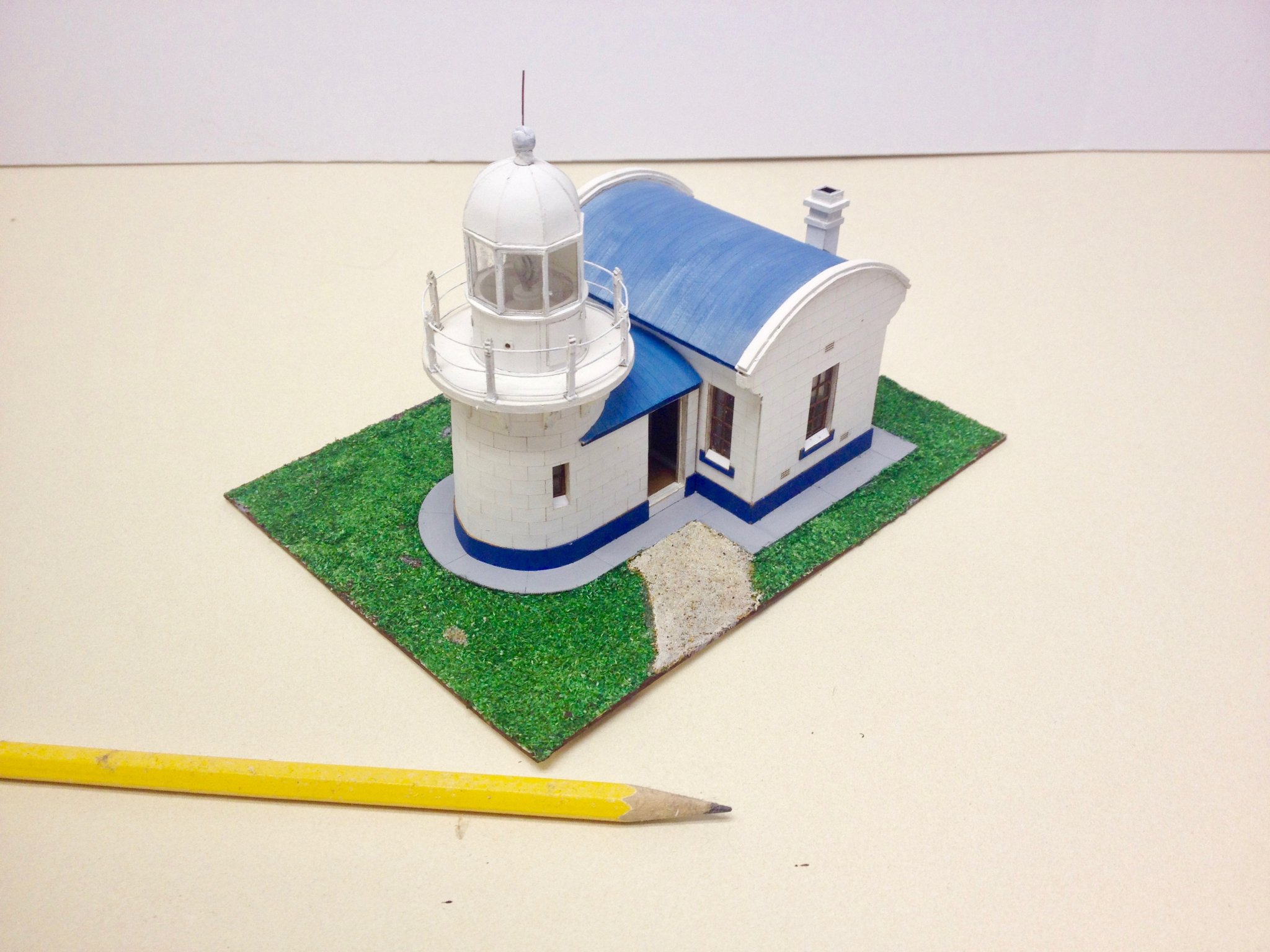
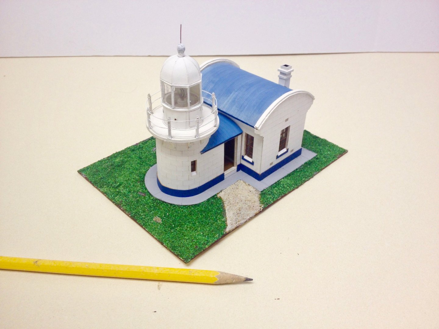
Hi VTHokiEE, looking over this kit, I don't see anything that you have to cut out, except for the flags. Everything else is laser-cut, so you just have to cut the tiny tabs that hold each part to the sheet. If you really like lighthouses, then some of the Shipyard lighthouse kits will give you some good experience with the laser-cut kits, but I don't really think it's necessary. I did build their Crowdy Head lighthouse kit, which was a pretty neat kit though. Very quick build, and you do get a good taste of what the Shipyard kits are like. Clare
- 175 replies
-
- 10
-
-
- hanse kogge
- shipyard
- (and 1 more)
-
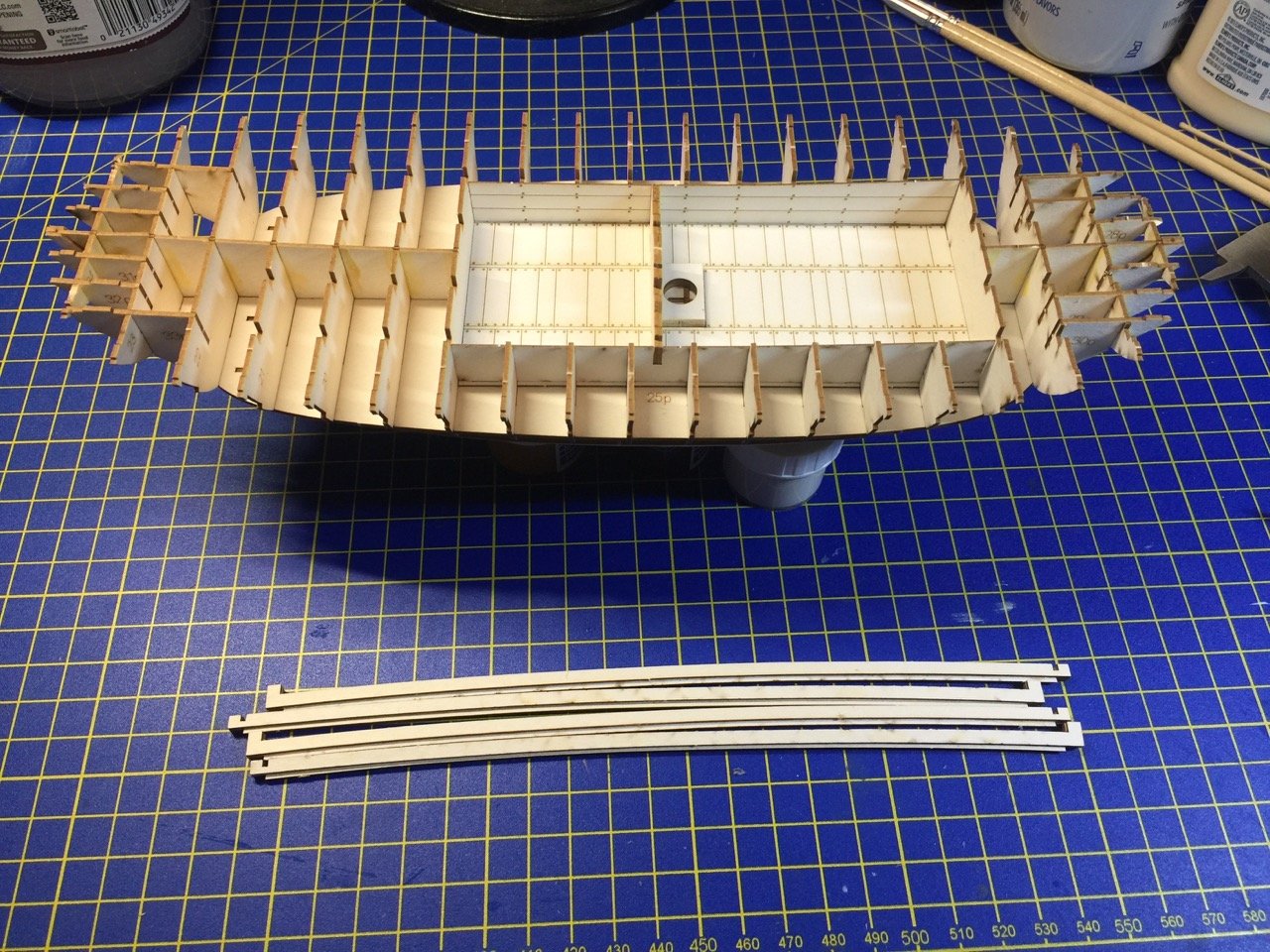
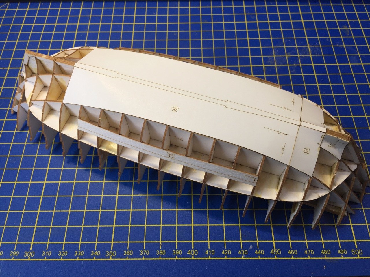
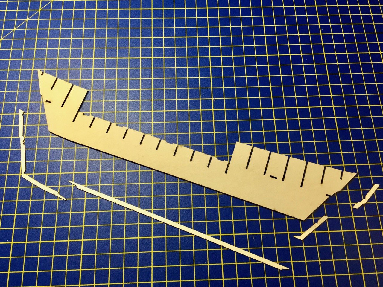
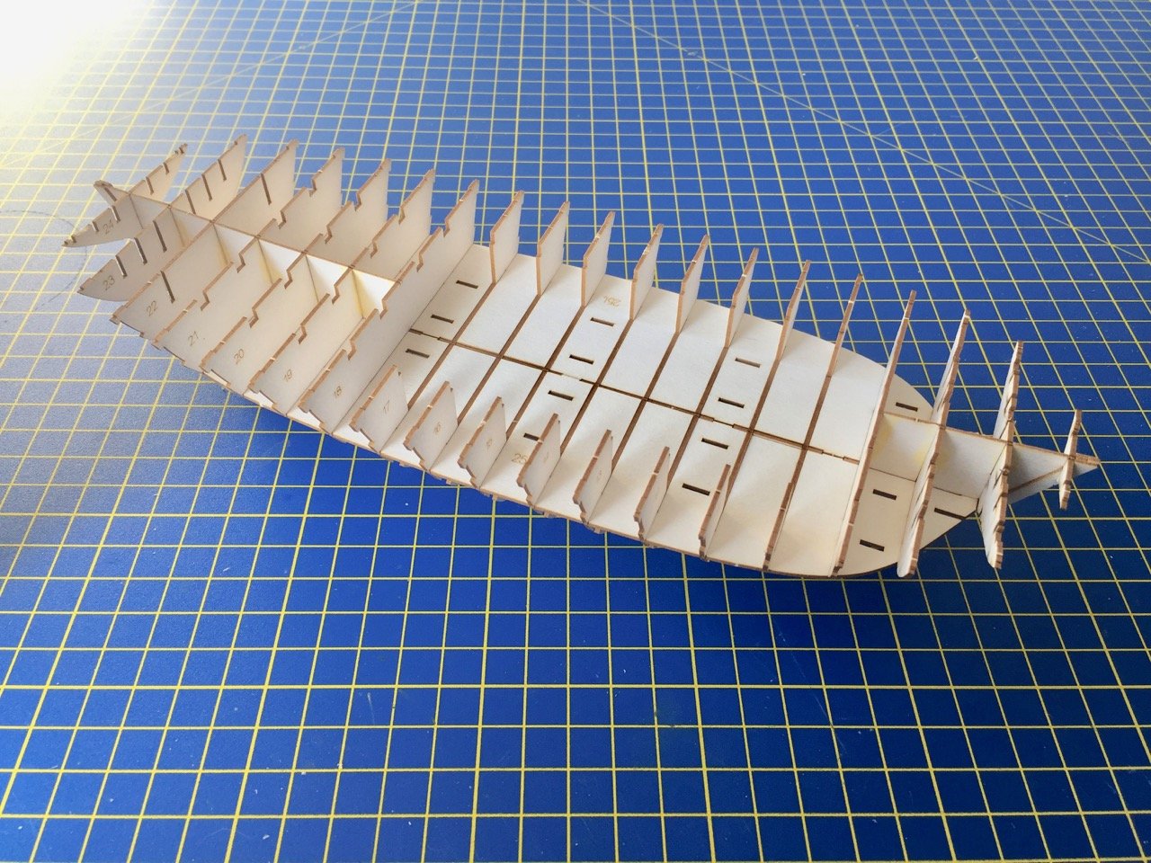
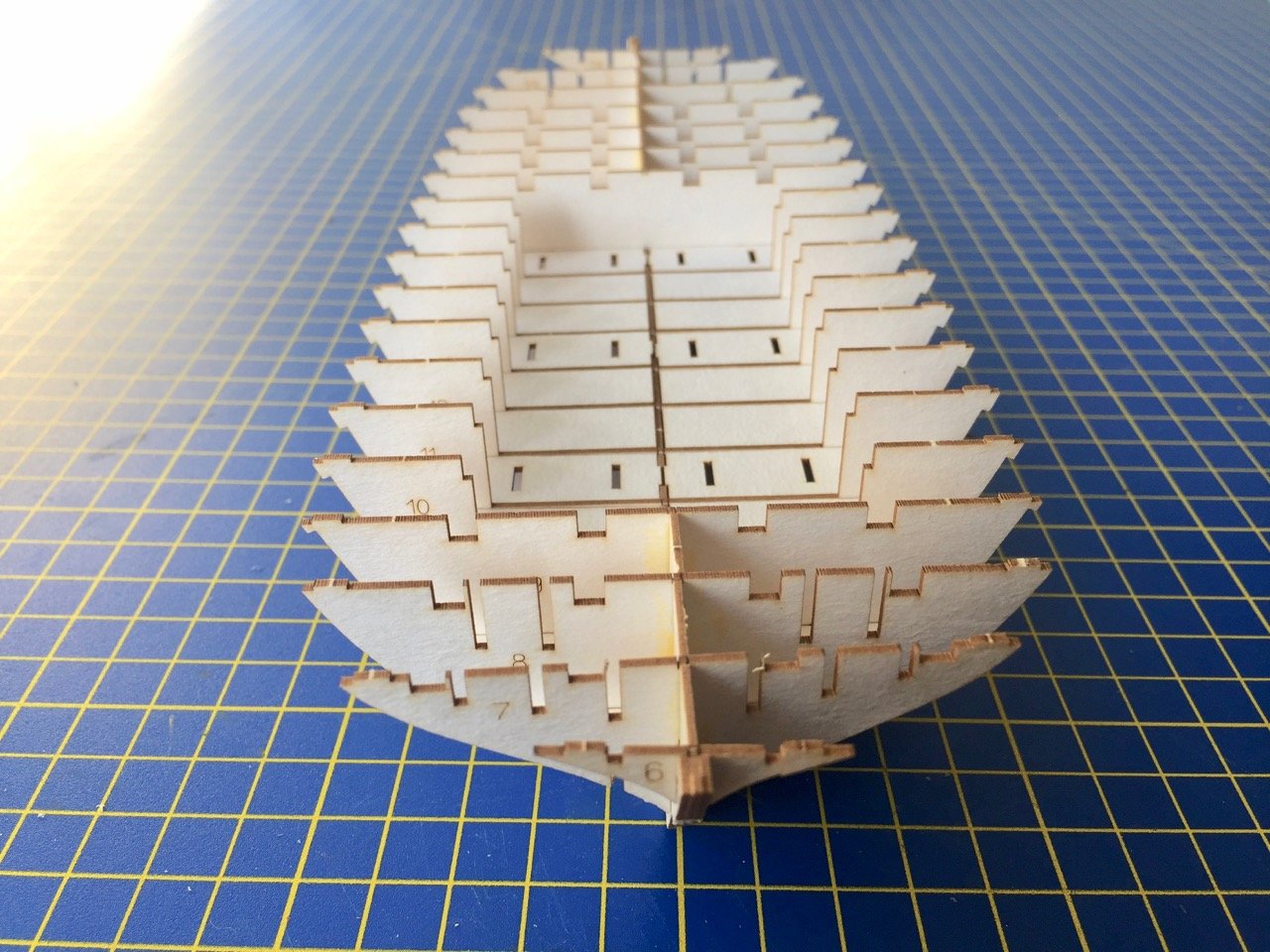
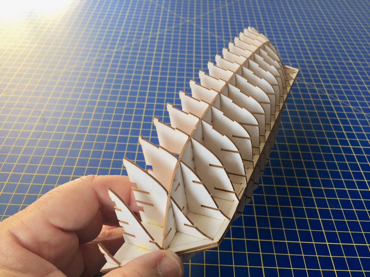
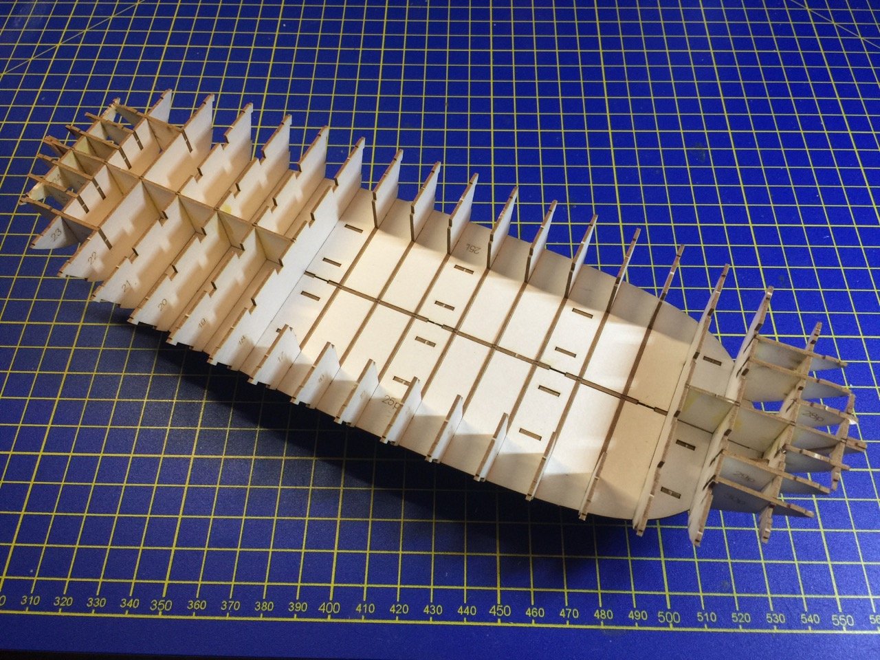
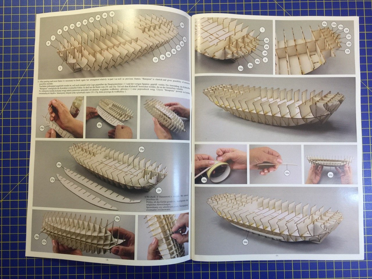
Chris, are you going to build the kit, or just do a review? Hope you build it. I'd love to see it going together. As for the Bremen Cog review, I'm thinking there is enough there to tell people what they want to know. One thing I'll add here, and as a disclaimer I should point out that this is kind of a plug for a company that I do some work for, but I kind of talked the owner of Ages of Sail into carrying the two laser-cut cog kits, plus a big order for their new wooden kit. So if anyone is considering building any of these, please consider buying from Ages of Sail! Now, on to the build... To start with, I used a scalpel to cut the needed parts from the laser-cut sheet. The instructions show a double-edged razor blade, but that seems a little dangerous. The scalpel works quite well. It is interesting that they laser-cut scarf joints. They look great, but they will get covered over later in the build. At this stage, I used simple Elmer's wood glue for these parts. It allows me some adjustment of the parts before the glue sets. In the photo above, it's a bit hard to tell, but the bow end is on the left side. The next step was to fit all the bulkheads and hull stiffeners into place. All the parts slip easily into place and no glue was used at this stage – I wanted to test fit everything first. Plus, I love how quickly the hull takes shape at this early stage. As you can probably see, once I was happy that I got everything into the correct places, I started adding glue to the joints. The close spacing of the bulkheads already gives the model a very solid feel, though the bulkheads at the ands are very delicate and they will buckle very easily, so a lot of care is needed in handling it yet. The above photo doesn't show the vertical stiffeners that are added next. There are two on either side of the keel. You can see the slots for them in the bottom of the bulkheads. There is also a piece that is added to the outer edge of the lower bulkheads. You can see the notches for them in the edge of the bulkheads below the lower deck. You'll see this in later photos. With the bulkheads all glued into place, you'll notice an interior space taking shape. This will be deal with in my next post. This takes me into page 6 of the 52-page kit instructions. The instructions here discuss their method of painting to give the model a wood-like appearance. Clare
- 175 replies
-
- 16
-
-
- hanse kogge
- shipyard
- (and 1 more)
-
Chris, Not a problem. I thought about posting in the review section. If it's editable, I actually have more photos of the contents I can add, as well as marketing photos from Shipyard. Robert, CDW, This really does seem to be a pretty awesome kit. I've built fully laser-cut wooden kits like the Japanese boats from Woody Joe, and it's a bit like that, but with parts that are more flexible than wood. The 1/72 scale keeps the model on the small side. But, with all the parts and laser-scribed features, I can tell it will be a very detailed looking model. My other paper projects have stalled. I have the 1/96 HMS Mercury and V-108 Torpedo Boat are sitting idly by. I'll get back to them both eventually, but they require a lot of cutting of parts. This was an opportunity to try one of Shipyard's laser-cut kits. I'd been drawn to their Dutch pinnace Papegojan and their HMS Wolf kits. But, when this opportunity came up, I had to jump at the chance. I'll post shortly about the actual construction, which is well under way. What I can say right now is that it's a lot of fun to see something come together so quickly and easily! Chris, I'm positive the Wütender Hund is going to be just as amazing a kit as this one. And, there's a wooden version out now! Exact same kit, but in thin wood. Ages of Sail has ordered a bunch of them, and they should be in the shop soon. Clare
- 175 replies
-
- 6
-
-
- hanse kogge
- shipyard
- (and 1 more)
-
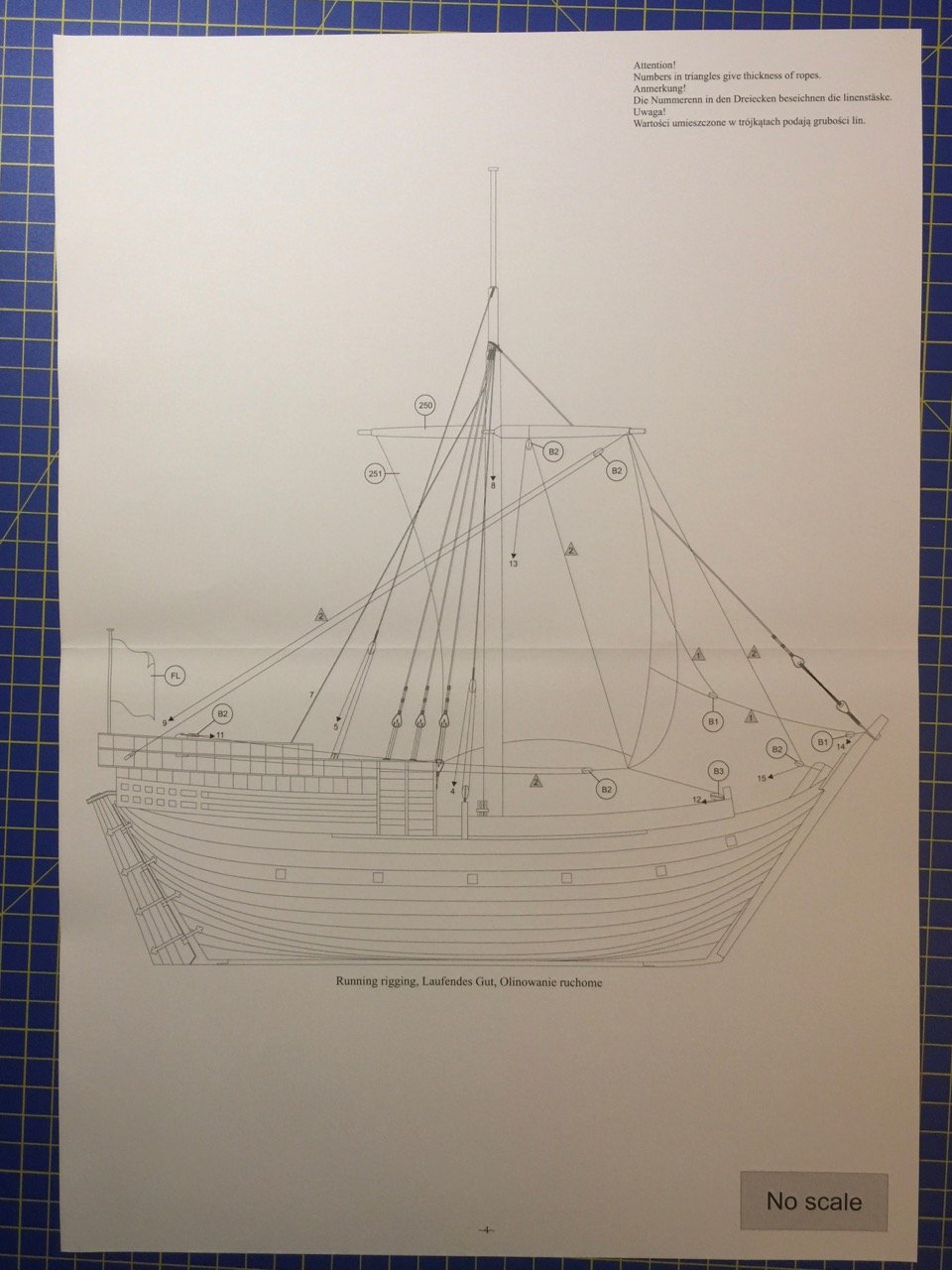
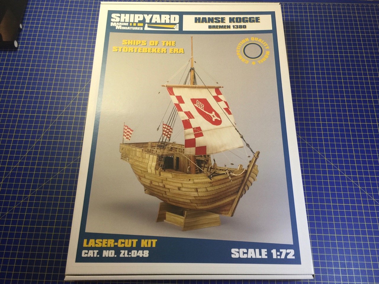
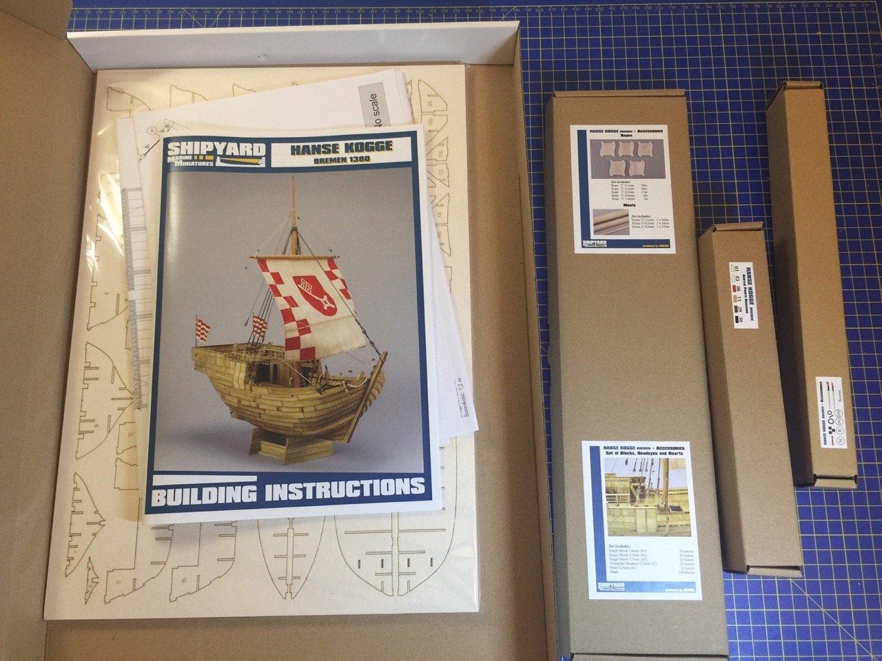
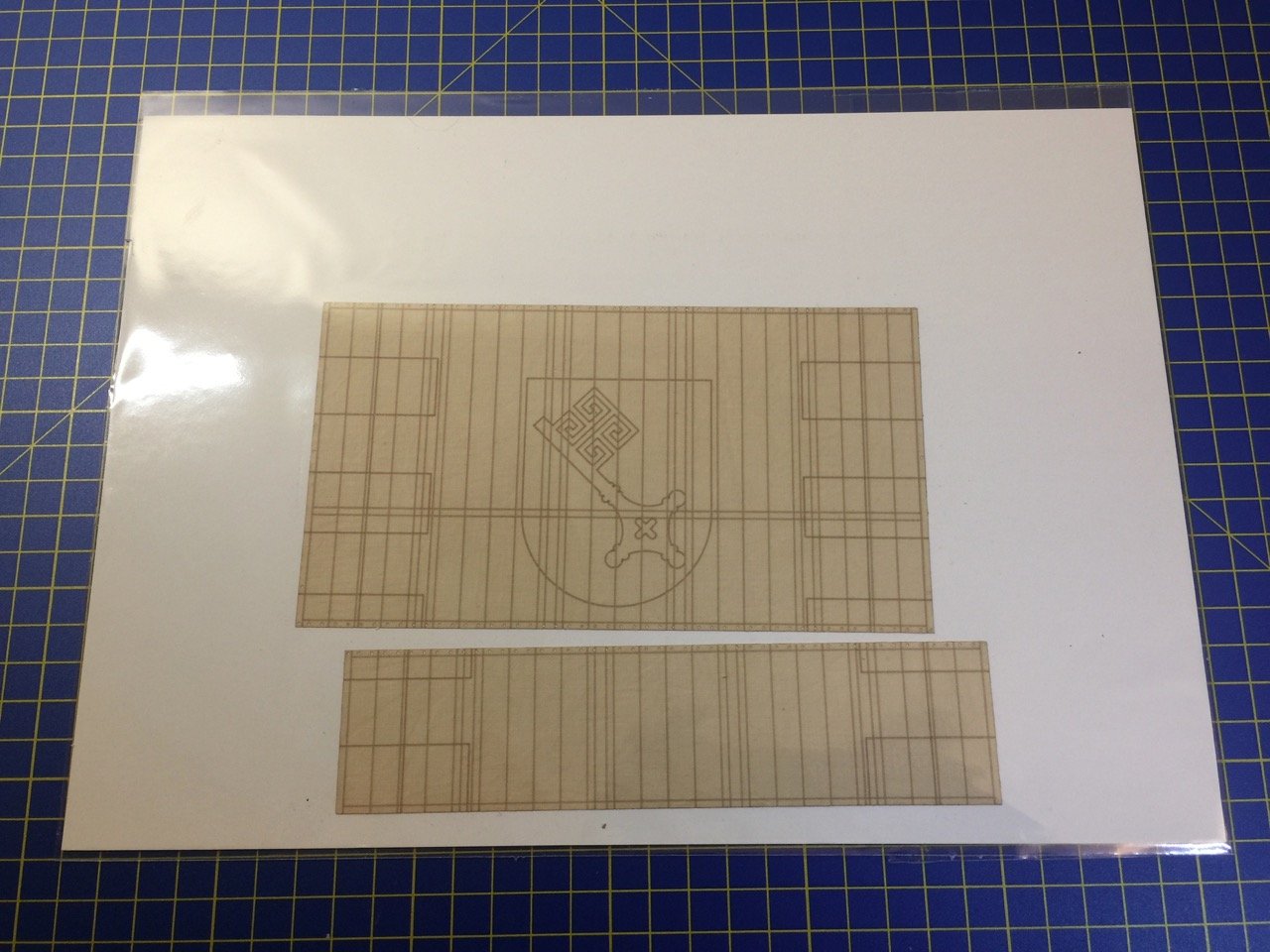
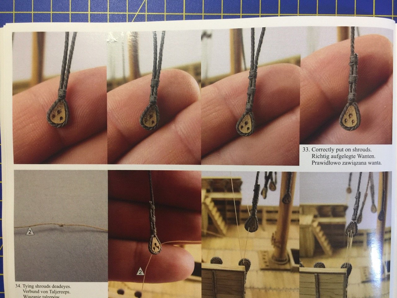
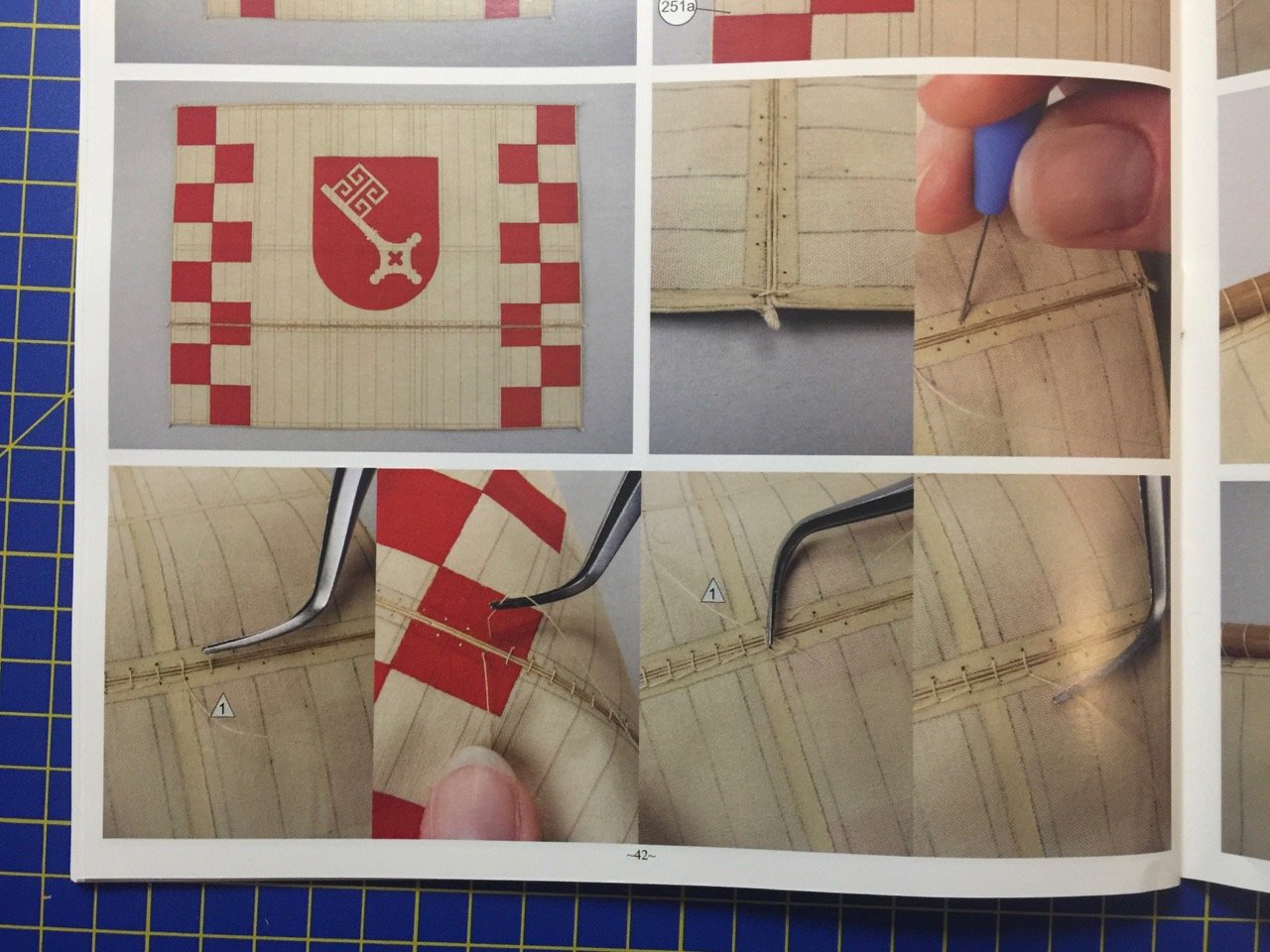
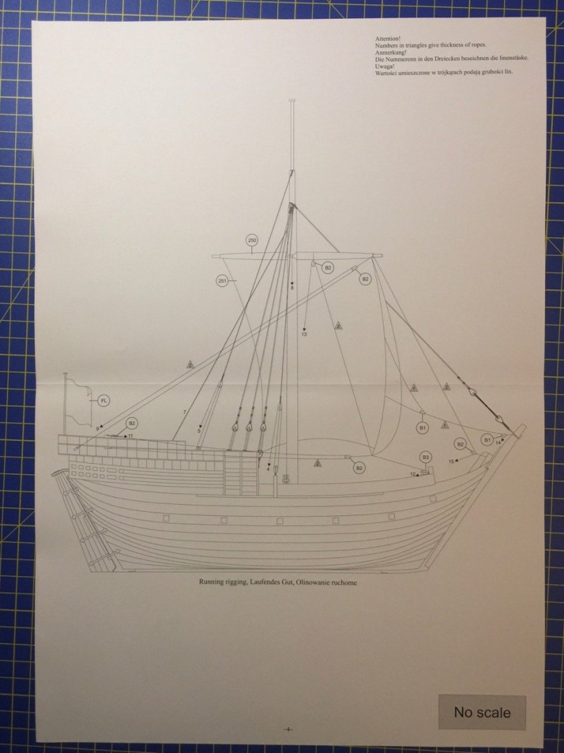
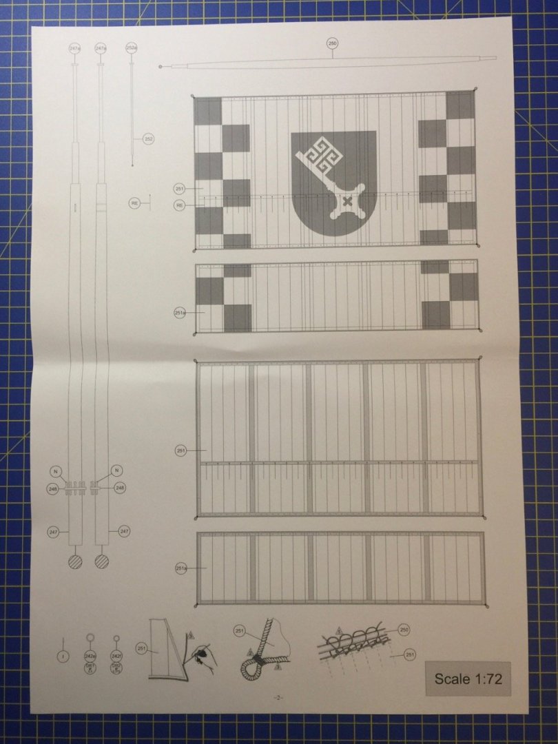
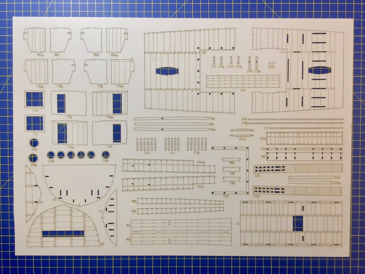
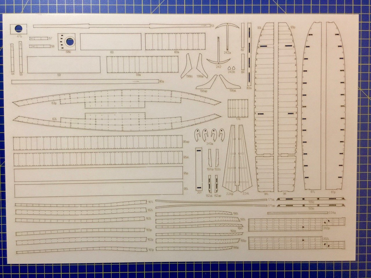
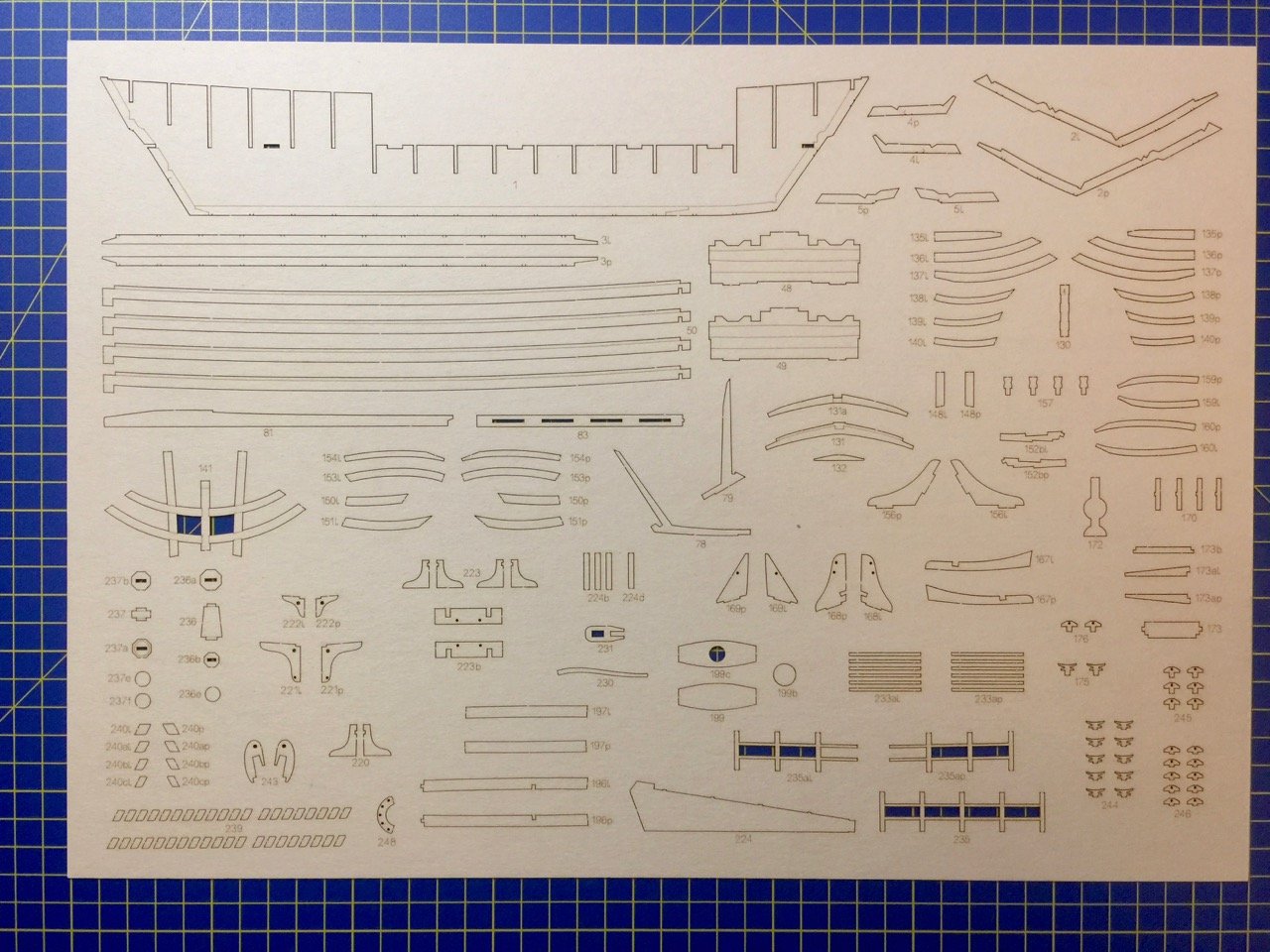
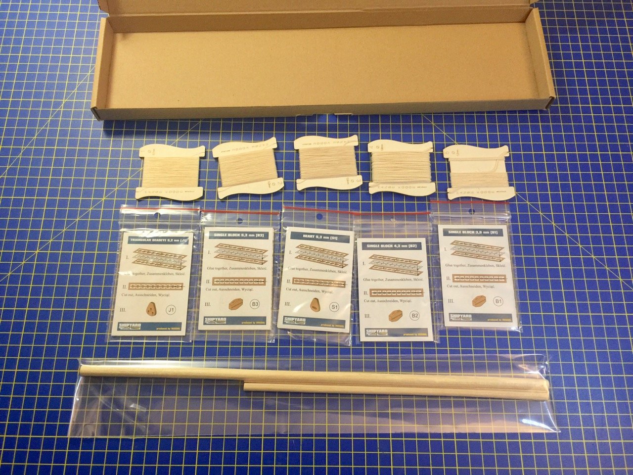
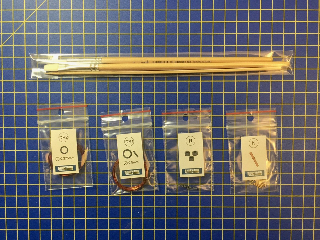
Earlier this year, I managed to acquire a relatively new kit produced by the Polish card model kit maker Shipyard. The kit is one of two that were released at least a year ago, maybe longer. Both kits represent medieval Cogs from the 1300s. Unlike other Shipyard kits I've worked on (yes, I only finished one paper ship model kit, but started a couple of them) which were paper kits and required cutting out pre-printed parts, this is a laser-cut card stock kit. Everything is already cut out in this type of kit, and the model requires painting. The kit I am building the kit listed by Shipyard as the Hanse Kogge - Bremen 1380. It is a 1/72 scale laser-cut kit based on the Bremen Cog. The completed model measures a little over 13" long and about 12.5" high. I decided to go ahead and take on this kit, though I have other projects, as the laser-cut design should make construction much simpler than the paper kits I've worked on. Ages of Sail, which is how I got my kit, sells this kit for about $125. There is a second Cog kit available called the Wütender Hund. It's a slightly bigger kit, maybe a little more complex, that sells for about $10 more. If you're interested in buying one, I'd really like to see other build logs! Here's a link to the kits on Ages of Sail: https://www.agesofsail.com/ecommerce/catalogsearch/result/index/?cat=72&q=Kogge So, taking a look at the contents of the kit... The laser-cut parts are in a cellophane envelope, individual carboard boxes keep things from knocking around in the main box and contain parts, paints, etc. The instructions make up a full-color booklet filled with photos. There's very little text, and what there is in multiple languages. Parts that aren't part of the laser cut sheets are provided in a couple cardboard boxes that include rigging line, laser-cut blocks and deadeye sets, paints, brushes, dowels, metal accessories, etc. The sail is pre-cut and pre-marked, but will need to be painted. There are several sheets of laser-cut card stock in various thicknesses and finishes. Some of the sheets have a glossy finish. Here are just some of the sheets. There are a couple sheets of plans included, which mostly cover rigging details. This looks like a very good kit and I'm pretty happy to be able to work on it. Next time, I'll post the start of construction. Clare
- 175 replies
-
- 17
-
-
- hanse kogge
- shipyard
- (and 1 more)
-
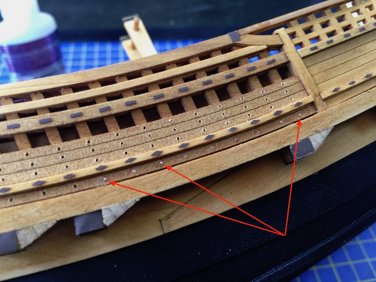
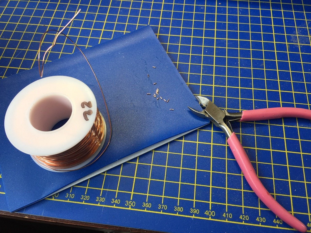
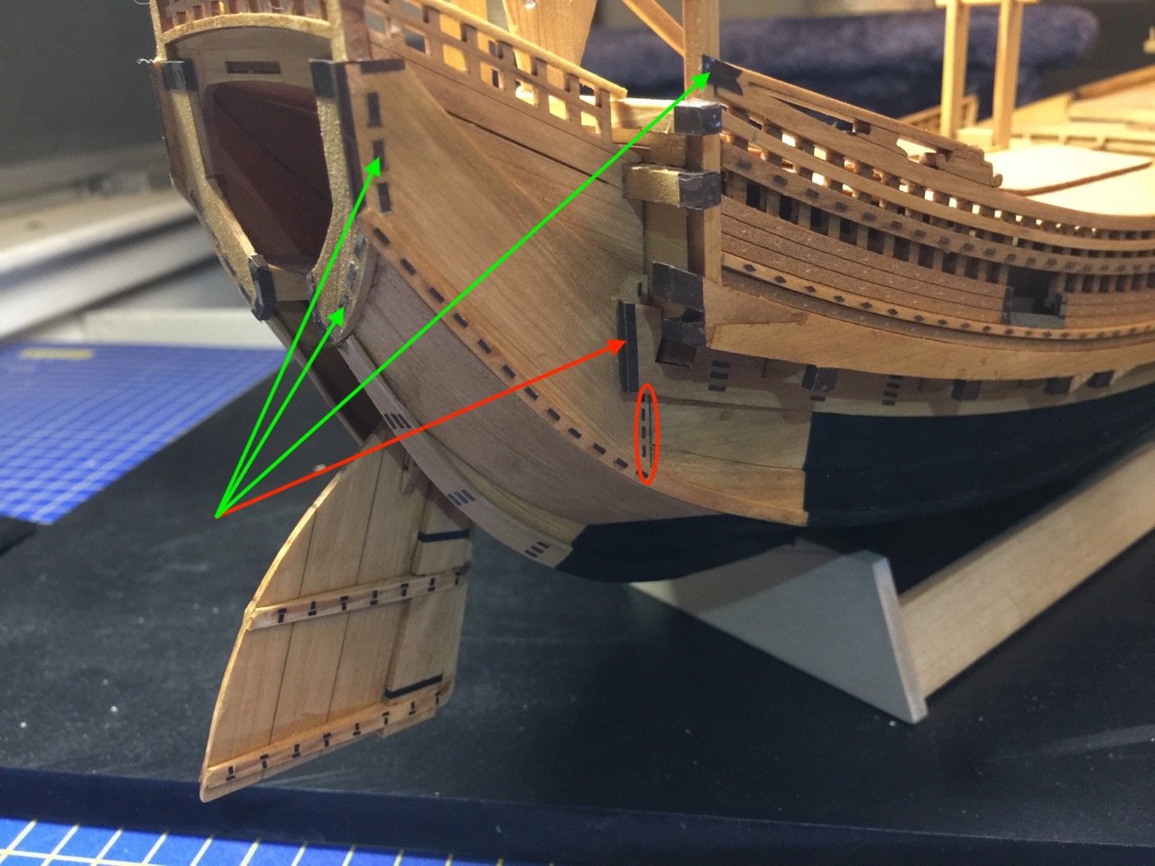
A quick update on the Kitamaebune model. With the completion of the vinyl "coppering" details, I started thinking about other non-kit details. The next item I decided is pretty straight forward and related to the vinyl "coppering" details. Often times, the coastal transports, known generally as bezaisen, are shown with nail heads in the bulwarks fences. Adding these at this scale may be a mistake, but I've started down the road – No turning back now. I drilled out all the necessary holes which will be plugged with some 22 gauge copper wire. I intend to blacken the wire using liver of sulfur. Holes were drilled out and I started the process of making copper "nails". The heads have to be flat, so I filed the end of the wire and then cut the "nail" off. I glued the finished nails into the holes and pressed them flat against the hull. The process seemed to work okay, though I won't really know how well I will like the results until it's all done. It's slow going, but there aren't really too many to do when you get down to it. In the photo above, the red arrows point to some of the copper nails after they've been place. There's a ways to go, but it's a start. As a side note, I'm going to need to start a build log for a card model that is connected with some new products that are being carried by Ages of Sail. Look for it in coming days. But, I will be pushing forward to finish the Kitamaebune fairly soon. Clare
-
Thanks Druxey! You always say the nicest things. Hi Kurt, I agree about the shape of the Honryou-sen. Most of the other boats I've seen of this style of construction are practically double-enders and don't have the nice "flowing look" to them, as you put it. At some point, I'd like to make a couple of them, but they are so simple looking with few details that they wouldn't be all that interesting to look at. Even the Honryou-sen is a bit simple looking, though I have a few small details I need to add to it. Plus, I need to make a kai, or paddle, for it. Clare
-
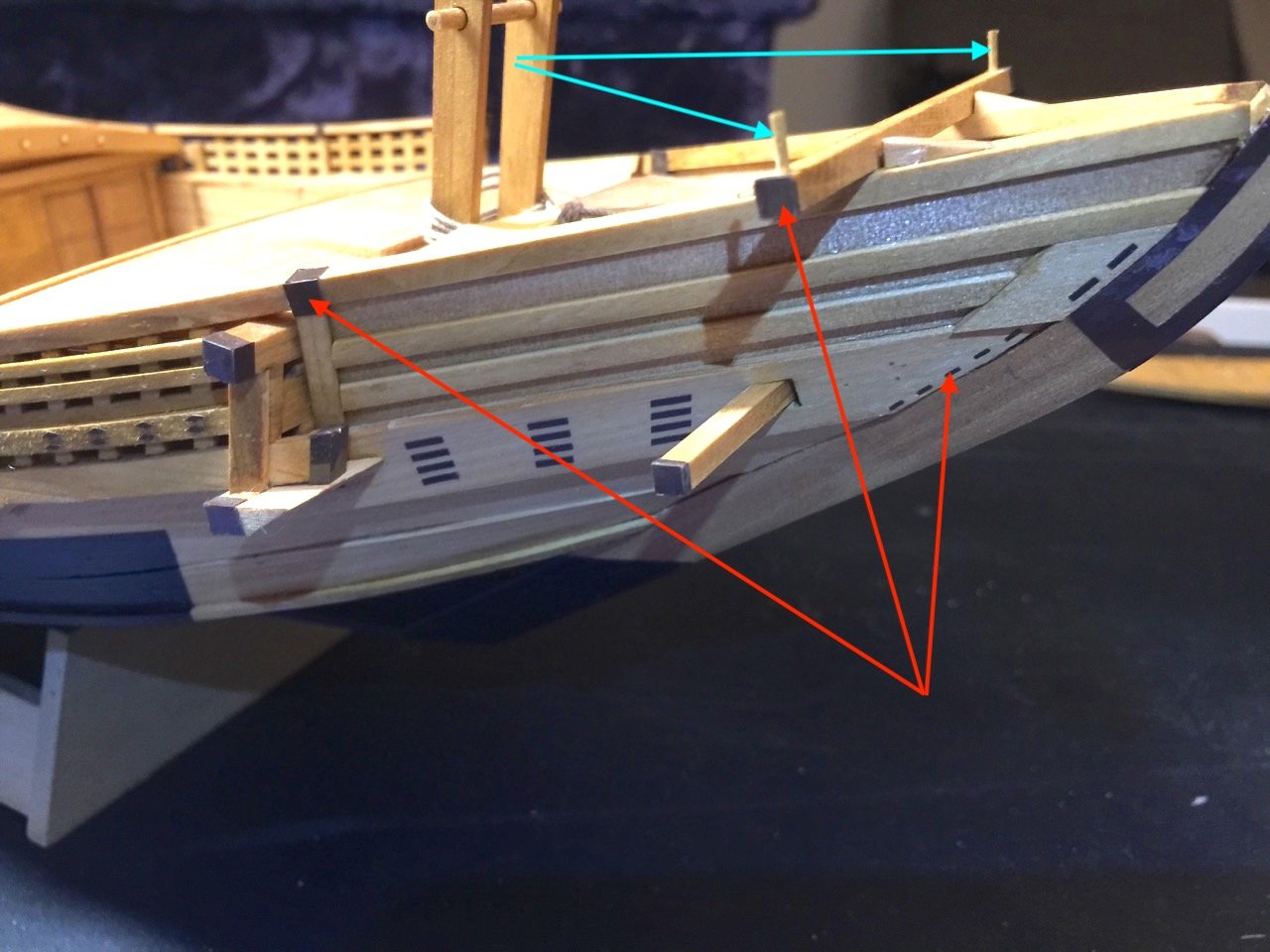
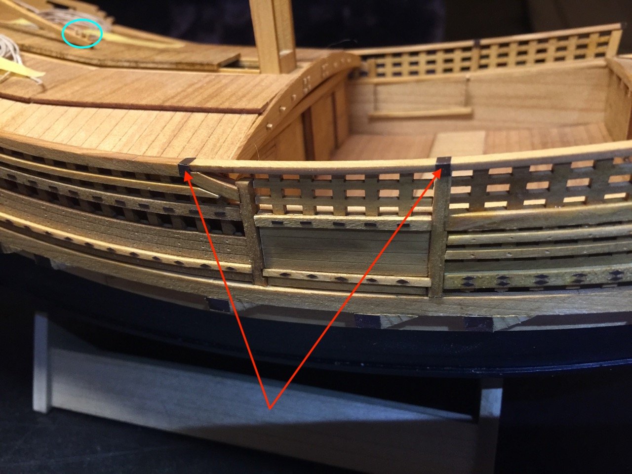
Getting back to the Kitamaebune model, I've finally made significant progress, though it doesn't really show. It's all in the small details – the simulated copper coverings are finally done! This took me a while as I kept thinking I was done. Then, I'd think some more and realize there was some other feature I wanted to add. I'd no sooner finish that, than realize I really should add yet another feature. This cycle has repeated itself many times, but I think it's over now. Kind of like getting sick and you think you're done – but nope... Of course, the end result with the model is a lot nicer imagery! In the images below, the red arrows and circles show newly added detail. The green show added detail that was actually based on kit part that I recreated in vinyl, as well as some small wooden posts I added to the beam at the bow and the end of the tiller. Still a lot of wooden details I need to add. But, this vinyl cutting phase looks like it's finally over, and I can put that equipment away. I'll be adding boat chocks, windlass handles, and will be considering adding the two small auxiliary masts that were often mounted on these ships near the bow. There are also a number of tenon joints that I want to simulate. I'd actually already done a couple, but found they were in the way of finishing the "coppering" detail.
-
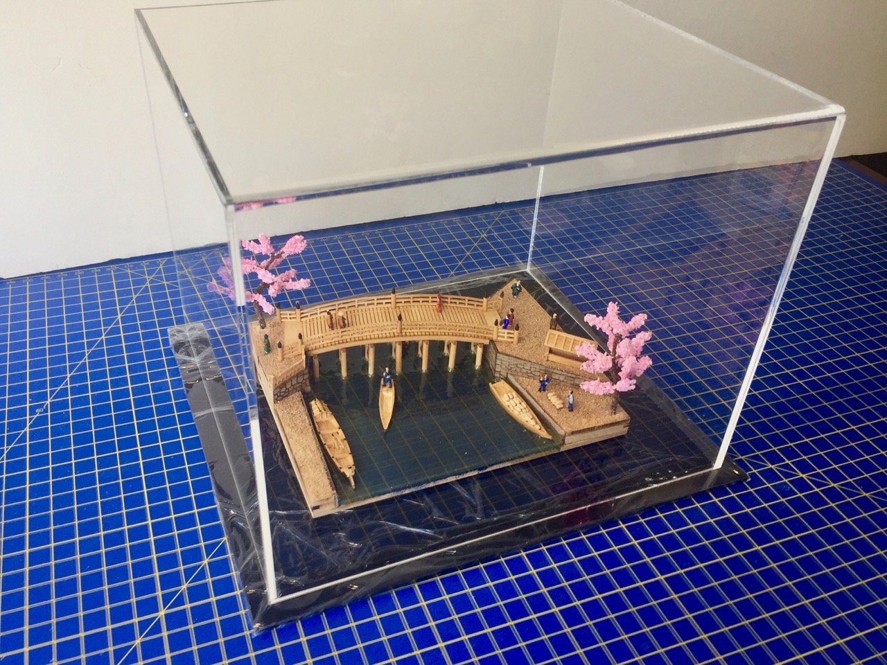
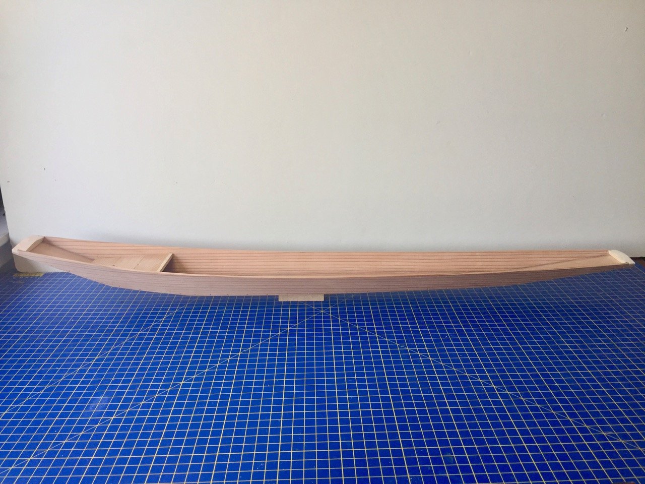
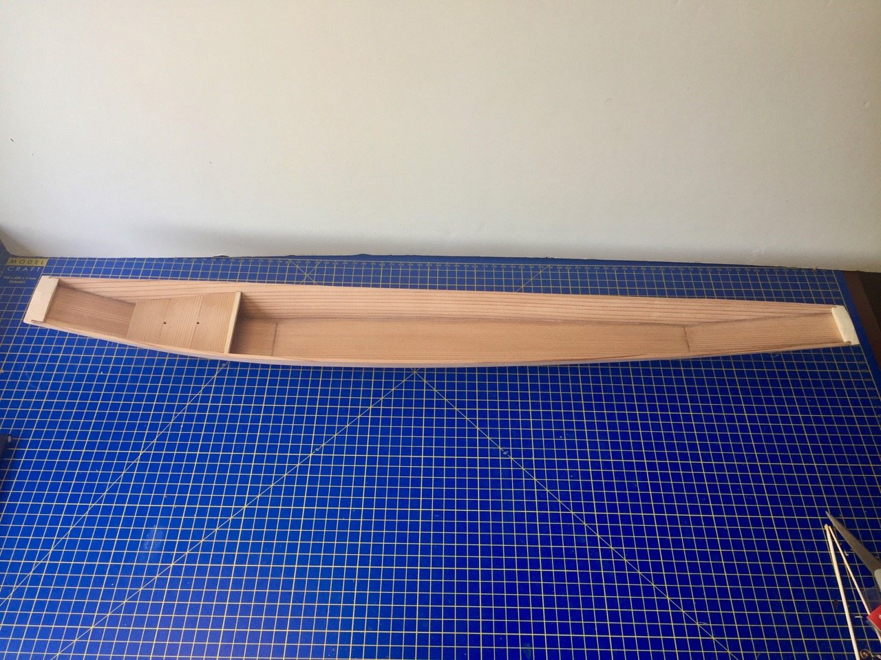
Here's a last aside. The little Nihonbashi Bridge diorama now has its case. It's a bit on the large side, but it was the closest standard sized case that would fit. I also recently finished a model of a 1-person riverboat from Niigata prefecture that was built by Mr. Nakaichi Nakagawa and Douglas Brooks last Fall. The model is a 1/10-scale model of a Honryou-sen, a type of fishing boat that was also used occasionally as a workboat for carrying gravel. It's a long model, and narrow. With no frames and only one beam, it was a bit of a task to keep it from twisting. There are two ringbolts that I may still add to it, one in the bow plank and one in the transom plank. It was propelled like a canoe, using a paddle. I have to make that too, still. I actually was making two in parallel, but got ahead with this one, so I could get it finished. Clare
-
Thanks Gary. The diorama is going inside a small acrylic case with a black acrylic base. The case just arrived yesterday and I'm very happy with it. It was $52 shipped and very nice quality. Nice to be able to put a build into a case so cheaply! Clare