HOLIDAY DONATION DRIVE - SUPPORT MSW - DO YOUR PART TO KEEP THIS GREAT FORUM GOING! (Only 13 donations so far - C'mon guys!)
×


Dziadeczek
-
Posts
644 -
Joined
-
Last visited
Content Type
Profiles
Forums
Gallery
Events
Everything posted by Dziadeczek
-
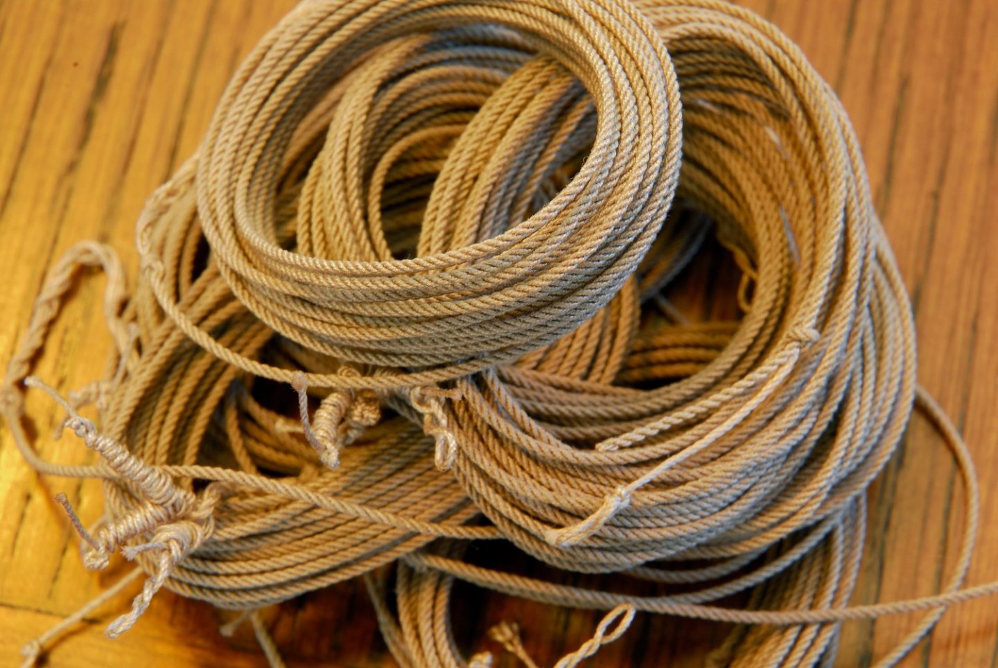
I always pre stretch my ropes right after I remove them from the ropewalk. Some time ago I got a large spool of linen thread from Barbour, if I remember. The thread is snow white and too stiff to make ropes from. I don't think one can get appropriate linen thread anymore. Who knows, maybe polyester instead of cotton, after all. But I found that polyester is even more "springy" and has this undesirable tendency to suddenly unravel once you cut it... 😕
-
 I would simply replace the planks with, say, cherry - it is a bit "stronger" wood specie, similar color, although with slightly more pronounced grain. If you cut new planks on a table saw, you can carefully select better areas from your board and make your cuts along the grain and not across it or at an angle. Cherry is a pretty common hardwood, so you should not have any troubles locating it in hardwood lumberyards in your area.
 -
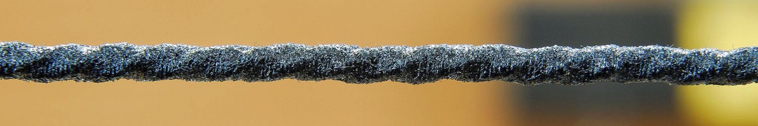
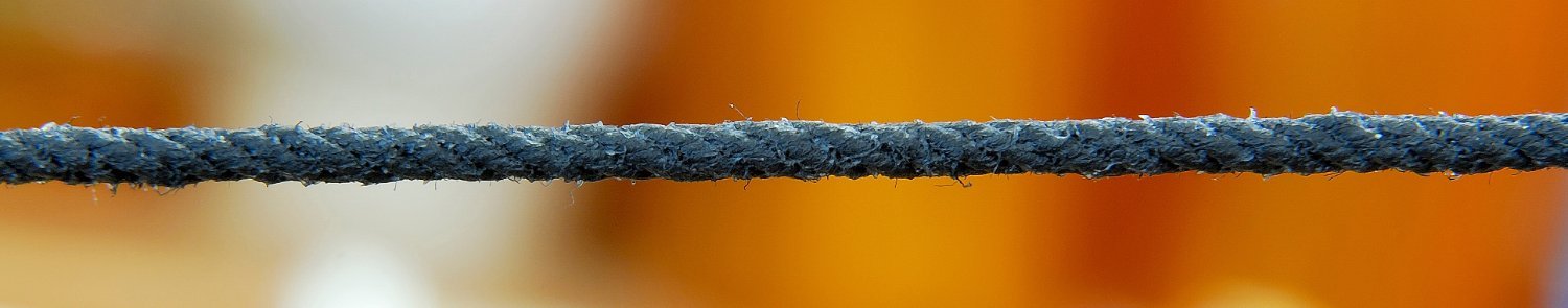
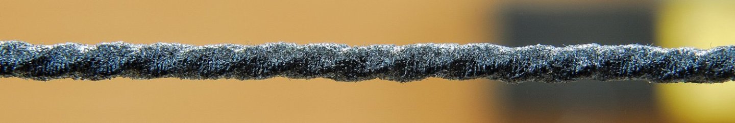
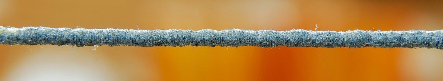
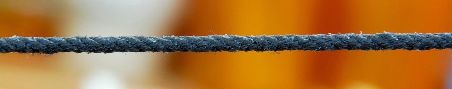
Actually, in my case, the cotton ropes get tighter when the humidity goes up (~70%) and the temps get down (~60 F). When the humidity goes down (~40%) and ambient temps go up (~75 F). the lines get loose and are sagging. As I promised, I did a little experiment out of the model. I stretched three pieces of rope (each ~ 18 inches long) and treated them with three different substances: Shellac, Wipe Poly satin and Testors Dullcote - these are what I had handy around the house. (I avoided any substance which is water based, since I thought it would not insulate the ropes well enough from moisture). After the first coat (brushed on), I noticed that the treatment has helped somewhat, but not enough. The ropes were still stretching and shrinking, albeit not so much. So, I repeated the same applications. Right now, I am waiting for the results, when the weather gets dryer/warmer (which is more normal for this area). I also noticed that shellac gave some shine to the rope - a bit undesirable... 😬 Wipe poly looks shiny and whitish. No... 😬 But after two coats of Dullcote (petroleum-based product), the third rope looks virtually indistinguishable - no shine and no color change!!! 😀 So, i think I will opt for this Dullcote for my rigging. I attach three pics of each rope treated with the above (in the same sequence). Notice that these pics are large enlargements of the original ropes, so the effects are somewhat exaggerated, when compared with the original lines.
-
Your attention to detail is mind boggling! 😲
-
Many thanks, Druxey and Bob Cleek, for your advice! I too was thinking about clear shellac, since white PVC glue, when dry, would still absorb moisture, soften up and allow it to penetrate into the ropes, and thus the situation would continue... Shellac should seal the ropes and stop the expansion/shrinkage phases, in relation to changing humidity. At least, in theory. I certainly will try it on a length of rope stretched outside of the model, and let you know the results. If it doesn't work, the model aircraft dope will be next. Thanks again! 🙂 Thomas
-
Is there a way to fix sagging standing rigging on my model? I made those from cotton threads which I twisted on my ropewalk. They looked good and when I mounted them on the model, they were fairly tight, just right, not too tight and not too loose. But, when we got wet this winter and cold weather came in here, those lines (mosty stays) became loose. At first I thought, I would pretend that "I did it deliberately to show natural way of slightly loose lines", but with each bout of rains and cold and subsequent warm/dry temps, sagging became too pronounced, I am afraid. If I tighten them some more, when the temps again drop down and we get more rains, they might became too tight and break, I fear. I don't want to replace them with synthetics - at this stage it would be way too laborious and probably impossible, maneuvering in the midst of this spiderweb of other ropes all over. Is there a way to gently coat them with something that would insulate them from the elements and excessive temp/humidity spikes? If so, what should I use? Thanks, Regards, Thomas
-
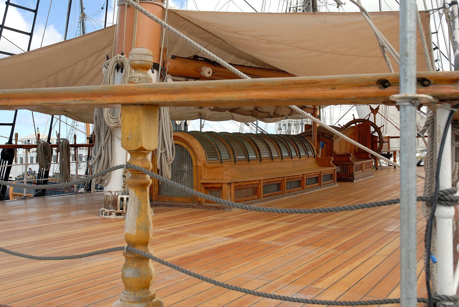
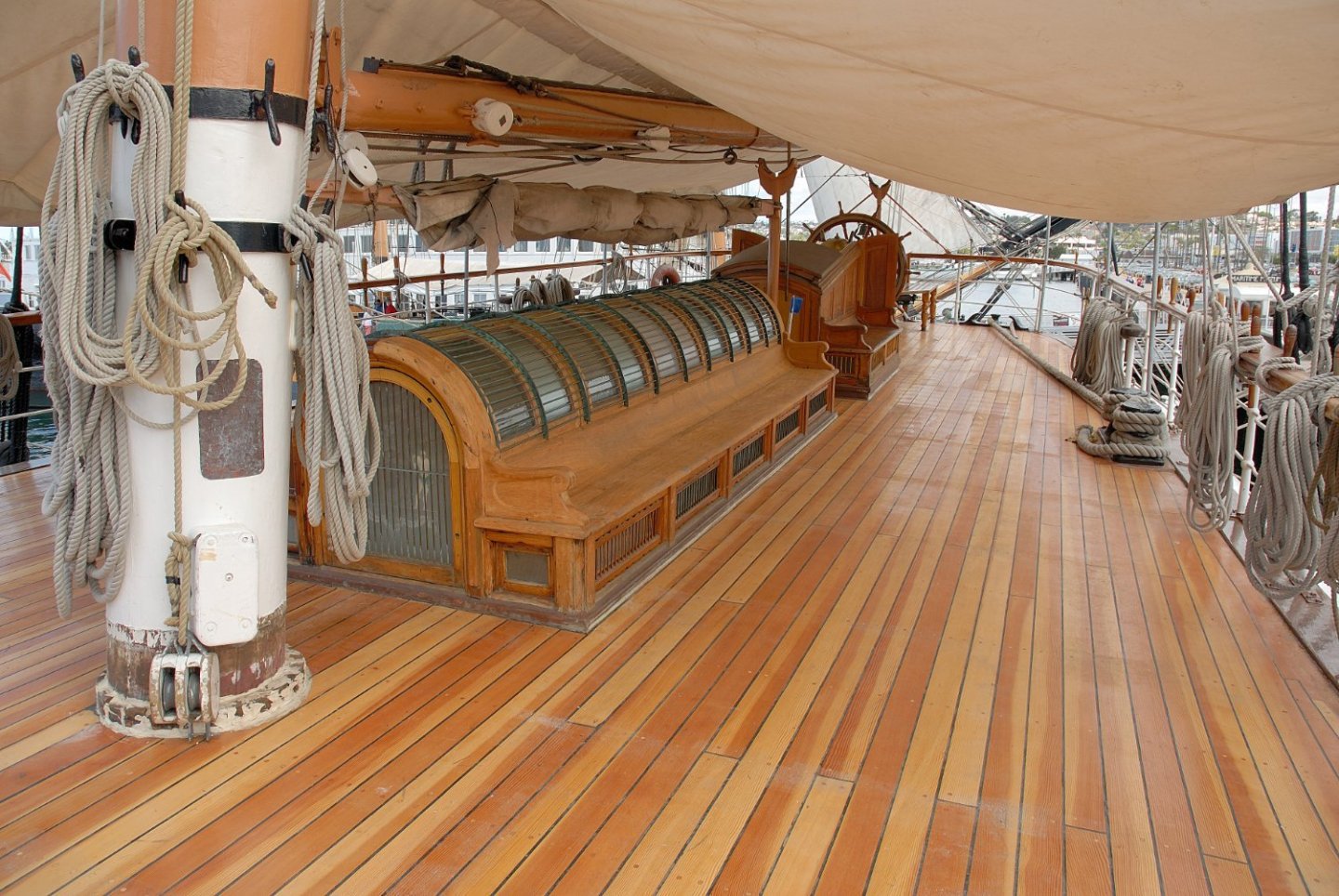
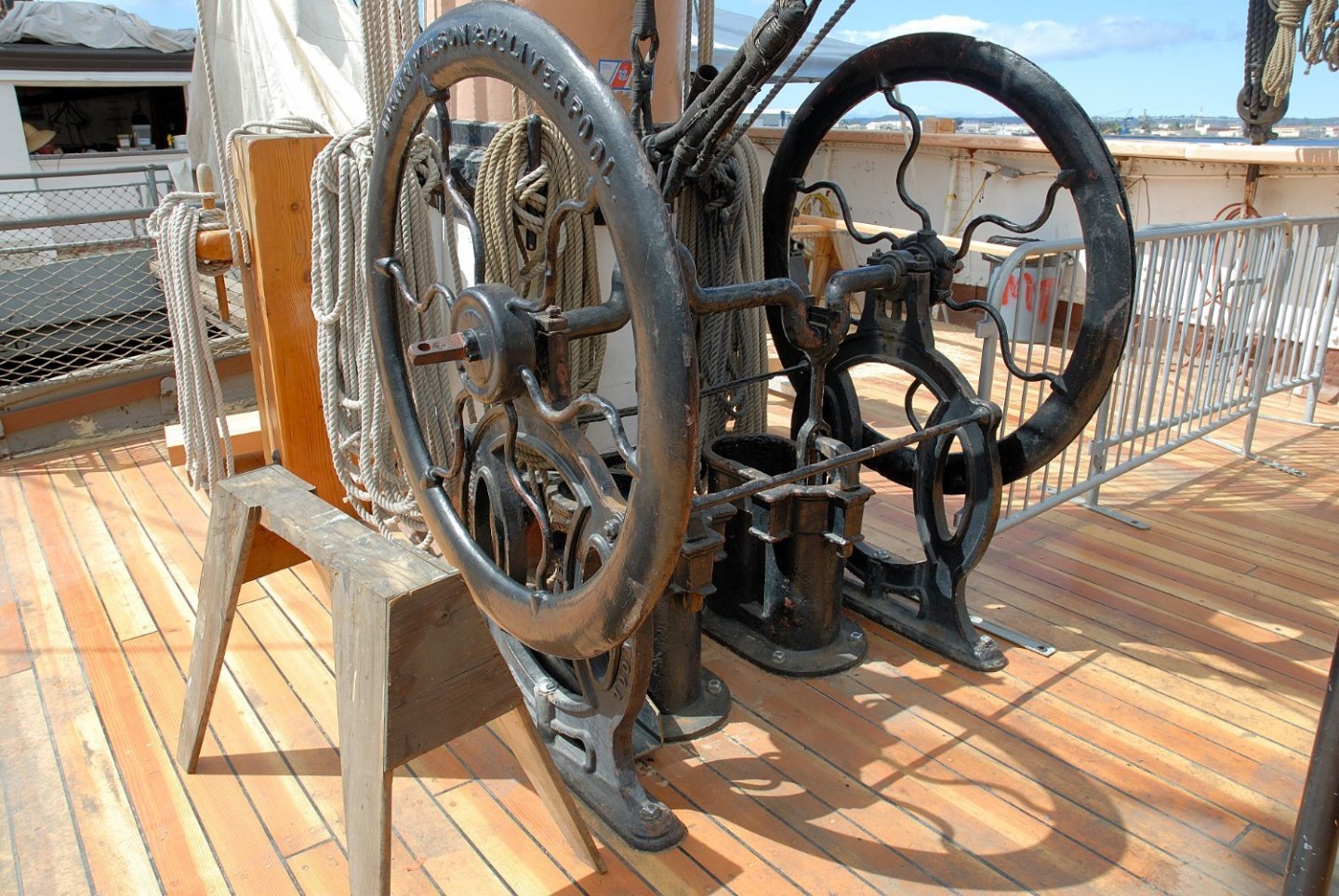
This is a brand new deck (replacement) on the "Star of India" in San Diego. You can barely see treenails there, but they can be seen, nevertheless, if you look carefully.

-
I see that you actually darned your mouses (mice?) Very good! EXCELLENT! Congratulations!
- 589 replies
-
- 3
-

-
- le gros ventre
- cargo
- (and 1 more)
-
Perhaps you should have preheated your brass strip to make it more pliable.
-
You can use white glue (Elmer's) or Titebond for wood. I wouldn't use contact cement - messy and smelly! CA glue sparingly, only in places where you cannot hold pieces in your hands and wait until wood glue dries.
-
Bulwarks placement
Dziadeczek replied to BMT's topic in Building, Framing, Planking and plating a ships hull and deck
I would first pre bend the bulwarks OFF the model so that their general shape follows the shape of the hull. Than I would use wood glue (either Titebond or Elmer's Glue All) placed on the edge of the deck and attach the lower edge of the bulwarks to this edge of the deck. To speed up the drying process, I would use a couple of drops of fast drying (gel) CA glue in the forward edge (on the bow) of both bulwarks, as well as in the stern area. Also, I would use strategically placed rubber bands to keep everything together while the glue dries. -
Mixing your paints with powder sugar will increase the adhesion to smooth surfaces like glass or metal. Try it!
-
Looking for Rattlesnake instructions
Dziadeczek replied to rattle snake corvette's topic in Wood ship model kits
And here are the Rattlesnake instructions from Model Shipways: MS2028_Rattlesnake instructions.pdf -
I found it for you here. Post # 4:
-
It all depends on what species of wood are we talking about? Certain species are less and other more difficult to bend, eg. ebony is very springy and extremely difficult to bend, whether heat bending and/or moisture bending are applied. Also, the size of planks is important; the thicker your wood is, the more difficult it is to bend. Sometimes you have to do it several times, repeatedly water soaking and heat bending, and so on. In some cases, especially if you want to bend it sideways (edge bending) it will be impossible - in such cases perhaps it is better to laminate the strips and, before the glue dries, bend them into desired curve clamping them in some sort of a form. Or cut the entire element from a bigger piece of wood. Generally, for typical wood and plank dimensions, found in most kits, it is sufficient to pre-wet the planks in lukewarm water for several minutes, perhaps even for half hour and heat bend them with a typical tool (I use an ordinary soldering iron with a heat control I made from a common household dimmer to prevent the wood from being burnt). If the curve is supposed to be quite tight, I repeat the process wetting the plank again, until I get the appropriate bend. In most cases, it is sufficient. It is not recommended to boil wood (damage of fibres) or soak them in ammonia or bleach (discoloration). For soaking the planks, I use a piece (about 2 feet long) of a white pvc pipe with one end permanently closed by a plug glued there, and suspended from an edge of my table, filled with water. I immerse my planks there and after a while they are ready for heat bending. I grasp my soldering iron with one hand, and a wet plank with the other, place it on a block of wood, and while gently rubbing it back and forth with the hot tip, I try to gradually lift it from the block. When I achieve desired curve, I stop. If I cannot bend it sufficiently without the risk of breaking the plank, I resoak it and repeat the tretment. If I overbend it, I correct it (underbend it) using the same method. A while ago there was an interesting article on the topic in now long-defunct magazine "Ships in Scale". This was, in fact, an interview by Email Klein with a German modeler Gebhard Kammerlander, who in detail explained the entire process. If you want it, I can find out the specific issue and let you know. Also, I attached a link to a short video tutorial on You Tube, of Gebhard demonstrating, what can be achieved with this technique named Biedesystem 3000 (he speaks there in German, but the video is 'in English' 😁 ) - search the archives here for this link, if you are interested. Greetings, Thomas
-
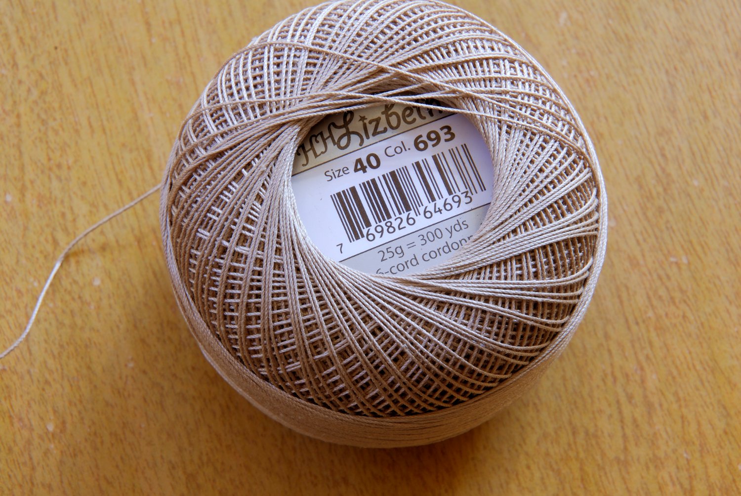
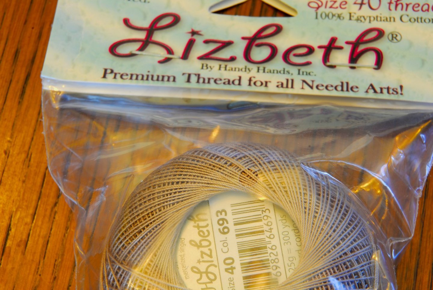
Perhaps some of the small vendors that make ropes, advertised here, might have what you need. Otherwise, I strongly encourage you to make your own ropes on a ropewalk, using commercially made thread, either polyester or cotton. That way, you can adjust the type of thread and/or its thickness to what you need. (besides, it is fun!) Now that DMC and Anchor threads are gone, I have recently had pretty good luck with cotton thread known as Lizbeth (available online), which is Egyptian cotton, traditionally one of the best, it comes in several thicknesses and colours and is already factory presinged, so you don't end up with fuzzy ropes. I make my ropes from this thread on my ropewalk. The thread is all factory right-hand twisted, so if you make your own ropes from it, they 'll all come left-hand twisted, otherwise, if you want them to be R-hand twisted, you'll first have to untwist factory given R-hand twist, turning in the opposite direction and continue your R-hand twist on your ropes thereafter. The question is, can you use this thread straight out of the spool? (after all, it already comes R-hand twisted, like most ropes on a ship). Well, the factory made twist on this thread is a bit too loose, you want your ropes look like natural ropes, just smaller. So, it is much better to twist your own ropes from this thread, with tighter twist, rather than using it straight from the spool. In the end, you' ll decide...

-
Does Shipyard Make a 1/96 HMS Bellona?
Dziadeczek replied to GrandpaPhil's topic in Card and Paper Models
Where do you find those pdf files from Shipyard? -
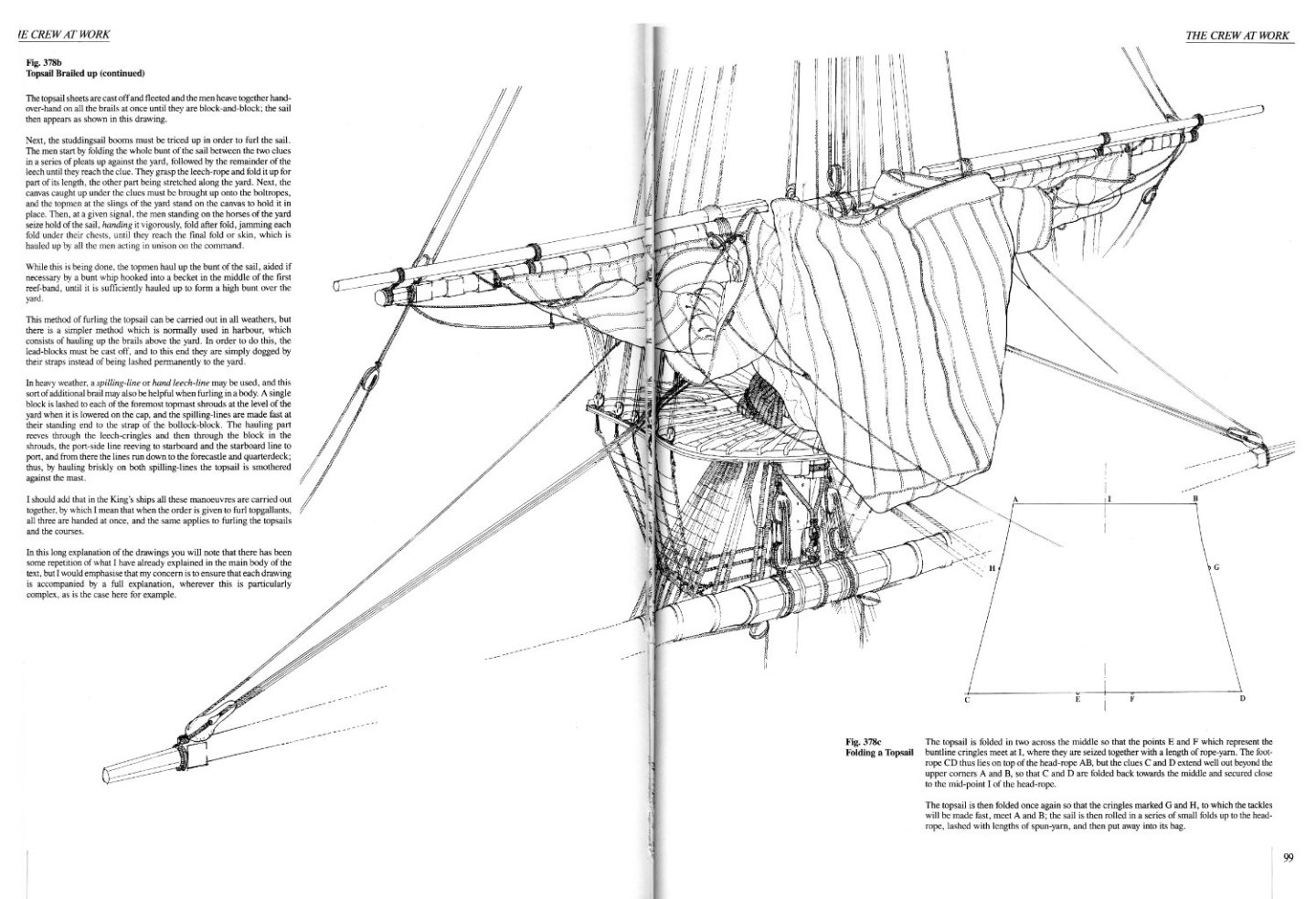
This is how J. Boudriot shows furling up sails in French ships of XVIII c. Hope this helps. Thomas
-
Hi, I too am building a model with sails attached. Very tedious and time consuming work! See the link below (post # 80): However I used thin cotton fabric - beige muslin, instead of silkspan, because I wanted to actually sew my sails and model all details on them, and with silkspan it would have been nearly impossible due to the thinness of a material. I show a sail configuration, known as "brailled up", that is only partially raised sails, instead of fully furled. I thought that fully furled sails would look too invisible, thightly wrapped up on the yards. On the other hand, fully unfurled sails would obscure some details on the decks and masts. So, I chose a compromise. Far from being an expert on this topic, I think I partially succedded with this detail, but I accept it, it is good enough for me... I think that the particular locations of all blocks, deadeyes and other details of running rigging, were on both, forward and aft sides of the sail, depending on the type of a ship, the time period and nationality of the vessel. These things varied considerably. See detailed instruction of your particular vessel. I am lucky that Mr. Boudriot was soo nice to include those details in his books, so I rely on him. Happy modeling! Thomas
-
Introduction - André Dethioux
Dziadeczek replied to Wonko the Sane's topic in New member Introductions
Awesome models!!! I used to live and work in S. Africa, in Natal, not too far from Pietermaritzburg and Ixopo. Worked as a medical officer in one of the Catholic missions. Sweet memories...! Greetings, Thomas -
I have some left over supplies of great boxwood blocks made by Lloyd Warner (unfortunately he doesn't make them anymore), which I am using for my French 74 gun ship model. Some of them, especially the smallest ones (2 mm), have holes that are a bit too small for my ropes. I enlarge them by gently drilling them with an appropriate drill bit held in the pin vise. The original hole will provide a guide for the bigger one. After I pass the rope through the new hole ( I stiffen the end of the rope with PVA glue to facilitate passing it through the hole), the bigger hole will be invisible in the block, covered by rope.
-
Hi Matiz. An awesome model you built. Wasn't it however already built in the past and you are showing us old pics? On the French forum you presented this model finished several years ago. (I was hugely inspired by your model while building my own version of the Boudriot's 74 guns ship in 1:48. Excellent work!!! Congratulations!!!) Thanks again, Thomas
-
If you have troubles locating an appropriate scraper, you can use a piece of broken glass (its sharper edge), just be careful not to cut your fingers during scraping (shaving) - for protection wrap the held edge of the glass with duct tape.
-
At about 3:15 min. into the video, he starts edge bending with his hot bending iron (you can use an ordinary soldering iron with a heat control).