Dziadeczek
-
Posts
645 -
Joined
-
Last visited
Content Type
Profiles
Forums
Gallery
Events
Everything posted by Dziadeczek
-

Jumbo sail "construction" detail question
Dziadeczek replied to juhu's topic in Masting, rigging and sails
This is from Lees "TheMasting and Rigging of English Ships of War 1625-1860". It all looks rather complicated, perhaps for your model you might simplify it a bit...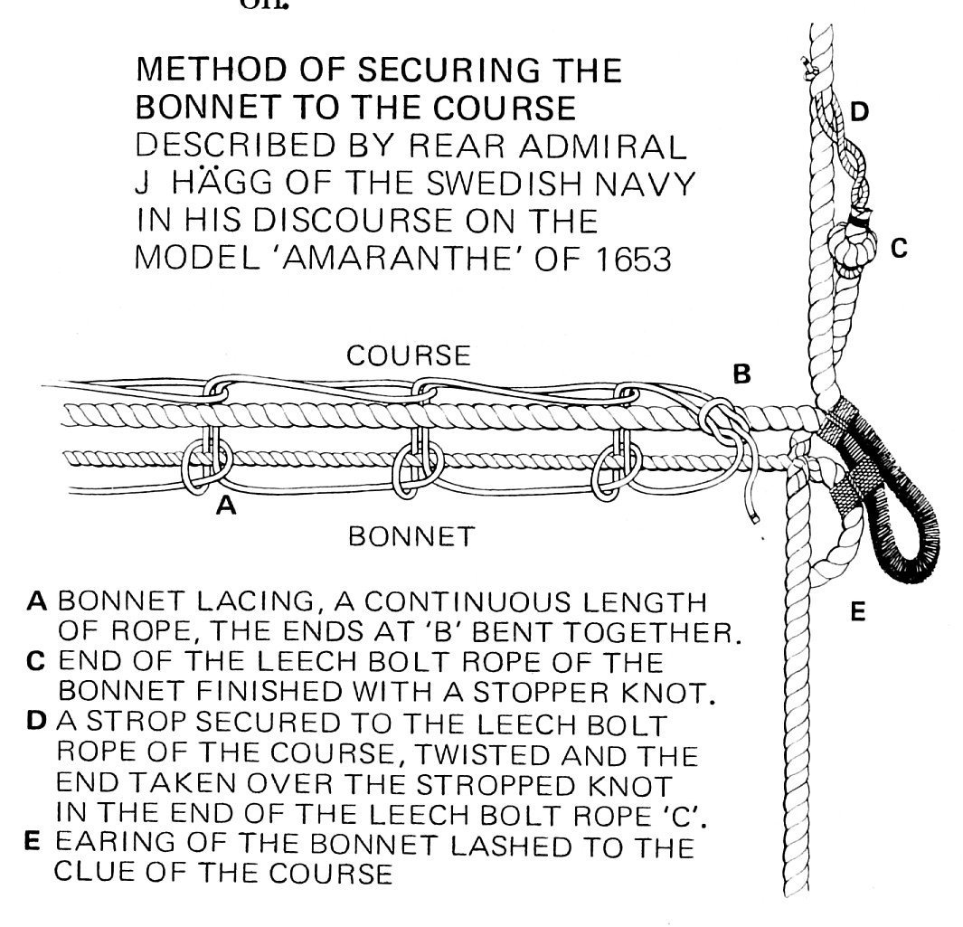
-
Jumbo sail "construction" detail question
Dziadeczek replied to juhu's topic in Masting, rigging and sails
Perhaps it is a bonnet, which is a piece of canvas that is laced together with the rest of a sail to make it bigger. That part you encircled in red might symbolize that lacing. -
How do you subsequently carve those reliefs in styrene? I am curious about the process, so, could you please, attach a couple of pics of your tools and the process showing it? Thanks! Thomas
- 2,696 replies
-
- 4
-

-
- heller
- soleil royal
- (and 9 more)
-
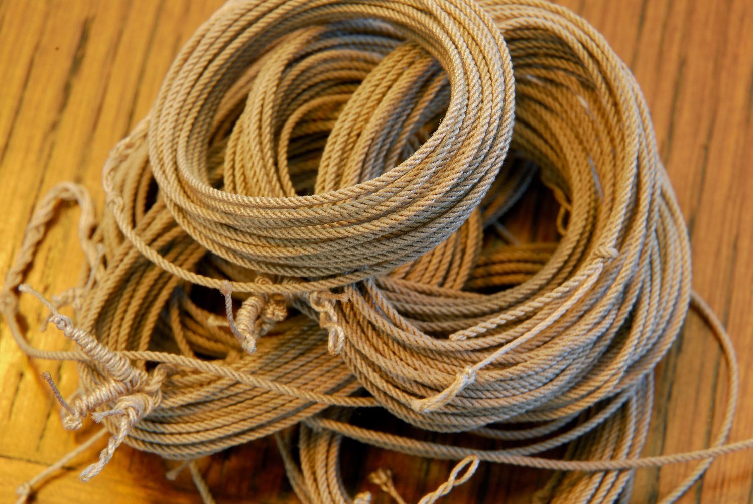
Yes, definitely! I always stretch my ropes just after they are twisted and removed from the ropewalk. Grab both ends with your hands and give the rope a stretch, until it is no longer 'springy'. Cotton ropes (especially longer ones on larger models) will in time stretch a bit, even after your pre stretching, due to changing weather and humidity in the air. For running rigging, it perhaps would be a desirable effect - looser, hanging ropes looking more natural, but for standing rigging (like shrouds or stays) not so much. So, you'll have to mount those rather tightly on the model, (but not too tight otherwise you might break the topmasts, or bend them excessively. )
-
If you make a rope from right hand twisted threads, your rope will be a left hand twisted type. If that's what you want, it is OK. But, as you'll notice, majority of ropes on a ship, are right hand type ropes, so you'll need left hand twisted threads in order to obtain right hand type rope from them. Always, the opposite - left hand type threads give right hand type rope, and vice versa. In my case, I had some right hand factory twisted threads (see pics), so I had to 'untwist' them on my ropewalk to obtain left hand twist on them, and then further continue left hand twist on them in order to finally obtain right hand twist rope.
-
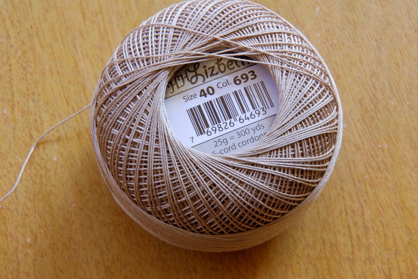
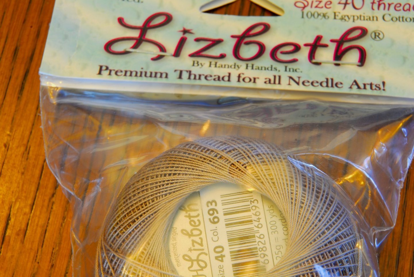
A while ago I bought some cotton cordonnet thread by Lizbeth - for crocheting, tatting and knitting purposes. I bought two sizes, nr. 40 and nr. 80 - just to experiment a bit with twisting model ropes from it, since it appears that the French DMC no longer makes theirs excellent threads, as well as the German Anchor bid the dust too. This thread already comes pre singed by a gas flame, so the fuzz is greatly reduced (for all those who for some reason are unable or unwilling to do it by themselves). It is made in China, but from an excellent Egyptian cotton, even, with long fibres, with no knots and unevenness. First trials turned out surprisingly well. The ropes came nice and even, the residual fuzz was eliminated by running the ropes through bees wax and burning it away. One other thing - pretty much all threads nowadays come as right hand twisted in factory, so, in order to obtain right hand twisted ropes from them, I had first to 'untwist' the factory twist and continue twisting threads on my ropewalk, to end up with right hand twisted ropes. But, that did not seem to be a problem... Here are some pics.

-
Work Table Recommendations ?
Dziadeczek replied to DanB's topic in Modeling tools and Workshop Equipment
Years ago I built a worktable (workbench) from plans in The Family Handyman magazine. It is very functional, serves me well through all those years, it is easy to clean and its size can be adopted to your space. Main advantage is that it doesn't have legs (it is permanently bolted into a wall, so cleaning junk from underneath is easy. Also, it is easy to sit close to it, with my legs under the drawers. The disadvantage is that it cannot be moved and/or taken away into a different location. It is permanent in its dedicated space. Here is a link to my earlier post (#3 there) -
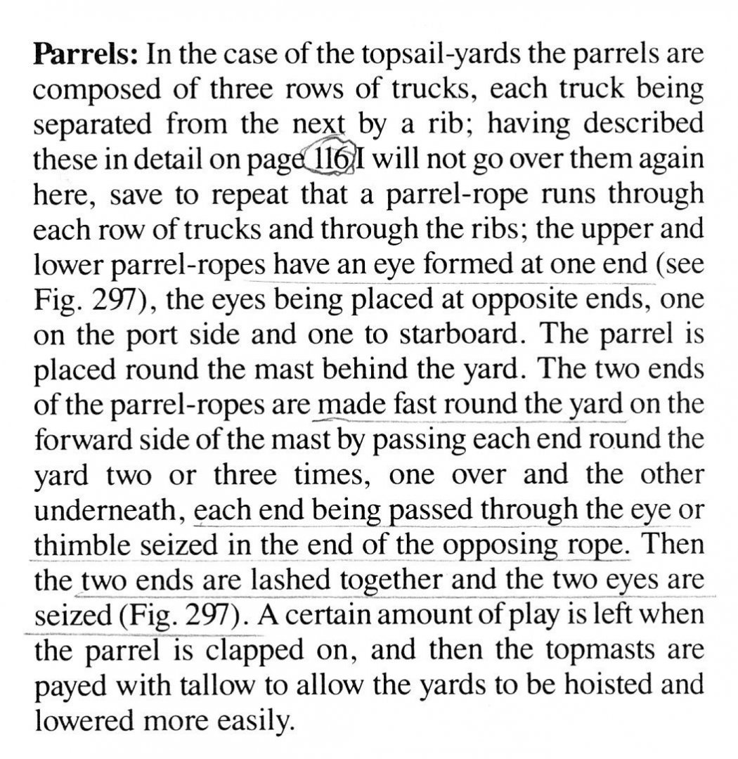
rigging to the French parrel, late XVIII C.
Dziadeczek replied to Dziadeczek's topic in Masting, rigging and sails
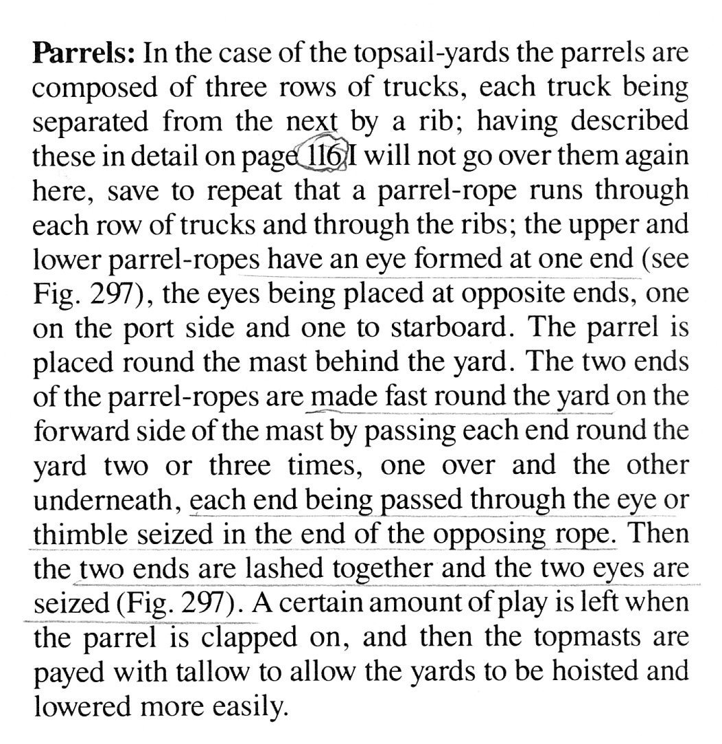
Hi Waldemar, That was exactly my understanding (English version of the book shows exactly the same), but I wanted for someone else to confirm it. I did exactly, like you suggested. Wrapped the parrel rope ends twice around the yard and tied them together crossing them in front of it. No falls whatsoever. Still, I am doubtful that they did not have a possibility to loosen/tighten it somewhat, when necessary... Thanks again! Thomas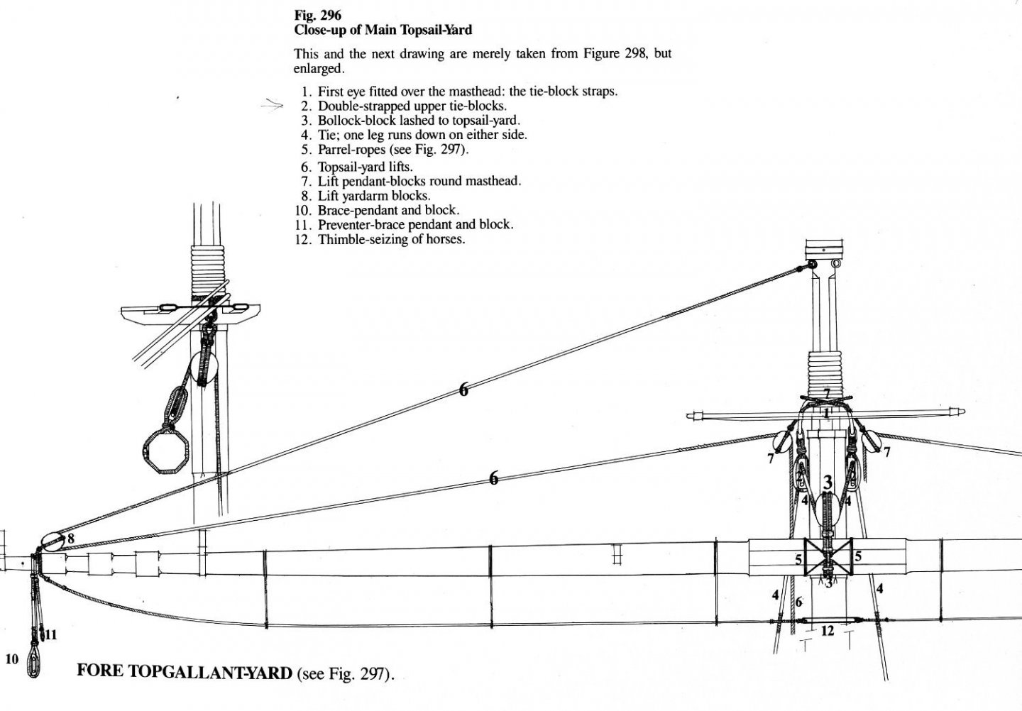
-
rigging to the French parrel, late XVIII C.
Dziadeczek replied to Dziadeczek's topic in Masting, rigging and sails
Thank you Mark, for your post. Yes, I have the book you mentioned. Before I wrote my question, I checked it. Among many details of rigging explained by Mr. Frolich, I unfortunately did not find sufficient explanation on their parrel. I need something like this, a drawing or a photo, showing where the lines (ropes) go. See post # 187 Unfortunately it shows a Dutch parrel, and a double one too. Perhaps the French one was similar, I don't know. And Mr. Boudriot doesn't show this detail in sufficiently clear way... Thanks again, Mark! Regards, Thomas -
Does anybody have a good illustration, perhaps a picture or a drawing showing the exact way of rigging to the French parrel for my 74 gun ship model? J. Boudriot in his vol. 3, page 160 doesn't explain this very clearly and his drawings, being very small and sketchy, don't show the parrel-ropes exactly how they should run. At least, I am not getting it... It looks like this triple row truck-and-rib parrels (identical for both topsail yards, the Fore and the Main) differ quite a lot in their rigging from English practices and, frankly, to me, don't make much sense. I am not seeing, for example, their falls explained, how they run and how this parrel was loosened and tightened? Any help will be very appreciated. Thomas
-
Aha! Everything clear now! MANY THANKS!!! 🙂
-
Fantastic workmanship! I am intrigued by this "cannula" of yours. Can you, in a couple of sentences elaborate, how exactly you use it? I see that it is a medical needle of sorts, mounted in a wooden handle. Do you pass its sharp end through the bight of the rope and then feed the end of your rope into the channel of this needle and finally pass this through the rope? Or else? Regards, Thomas
-
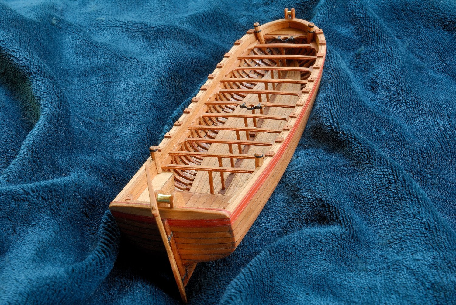
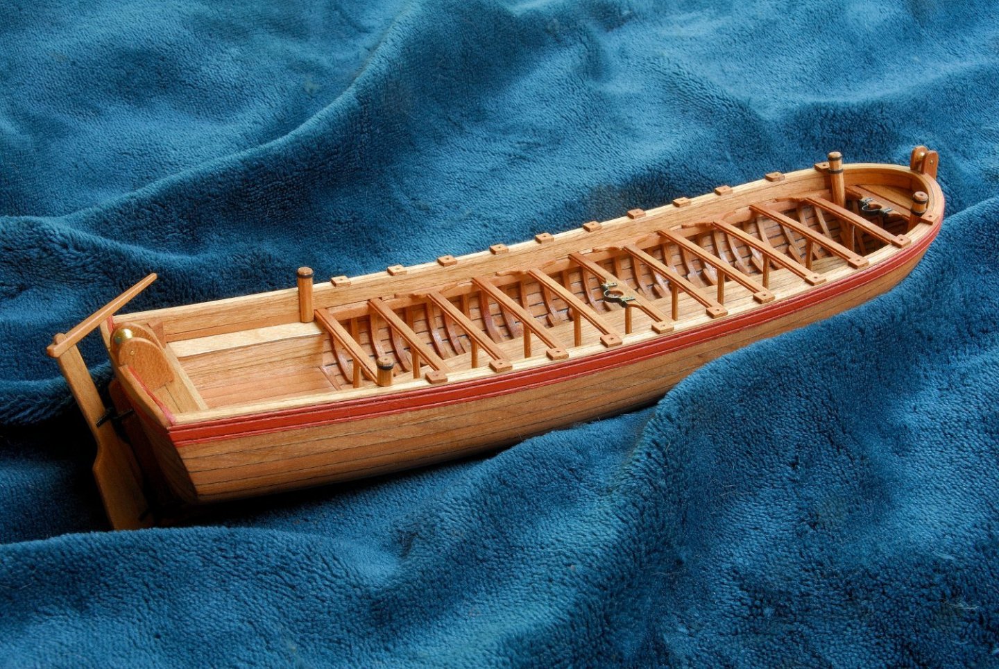
For my French 74 g. ship, I built the transom of my longboat from individual horizontal planks, following J. Boudriot.

-
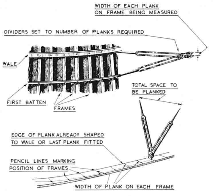
Slight degree of edge bending with heat of pre wetted planks is possible, so either side is OK for spiling, the top or the bottom.
-
My metal ruler was wrong.
Dziadeczek replied to modeller_masa's topic in Modeling tools and Workshop Equipment
Masa, you did not align both rulers precisely - hence you have this discrepancy. Go ahead and ALIGN them again. I have a feeling that everything will be OK, judging by your photographs. -
Hairy/fuzzy rigging thread
Dziadeczek replied to The Gimps Chimp's topic in Masting, rigging and sails
You have to do the burning off rather quickly, passing your thread over the flame, otherwise you run a risk of burning away the thread itself, especially polyester which melts in heat easily. -
Masking tape lifting
Dziadeczek replied to Jeff5115's topic in Painting, finishing and weathering products and techniques
Tamiya masking tape -
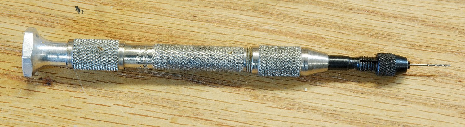
Looking for a good "starter" pin vise set
Dziadeczek replied to Capella's topic in Modeling tools and Workshop Equipment
Greg, It doesn't matter if the handle is made of aluminum or some kind of plastic, or similar. What matters is the material used for those jaws. It should be hardened steel, so it doesn't wear off quickly. I just had a thought. What if I use a 3 jaw chuck from Dremel (it looks like it does have hardened steel jaws - I bought them for my self-made serving machine, to keep my ropes tightly apart while serving). It is easily obtainable from most hardware stores for little money. I just need to fashion a shaft for it from a piece of a brass rod . Drill the rod on one end to accommodate the length of a drill bit placed inside and cut a proper thread for the shaft to be able to screw on the Dremel chuck. I checked it, by the way, - their chuck tightly holds # 80 drill bit! And everything else up to 3 mm thick. If I want it, I can attach on the oposite end of this rod some sort of a spinning head, wooden ball or similar, to hold it comfortably in the palm of my hand. By the way, the thread size for Dremel shaft is proprietary, but the size of a cutter M7 x 0.75 will work just as well. -
Looking for a good "starter" pin vise set
Dziadeczek replied to Capella's topic in Modeling tools and Workshop Equipment
I too am looking for a new pin vise to replace my old "General" brand vise, which recently developed a round hole in the center of this 'cross' (see red arrow) and is unusable for the smallest drill bits. I resorted to attaching a separate pin holder to it, but this is only a temporary measure... Greg, can you tell me, if your new vise can firmly hold a drill bit # 80? I don't mind paying more for Starrett, but 90 (!) dollars is a bit stretch for my pocket... 😬 Also, I am looking for a vise that has these two double ended collets, with two different openings on their BOTH sides - for convenience's sake. As far as I know, Starrett doesn't make such a vise; you have to buy two of their separate vises to accommodate drill bits from # 80 up to 3 mm thick. 120 bucks later...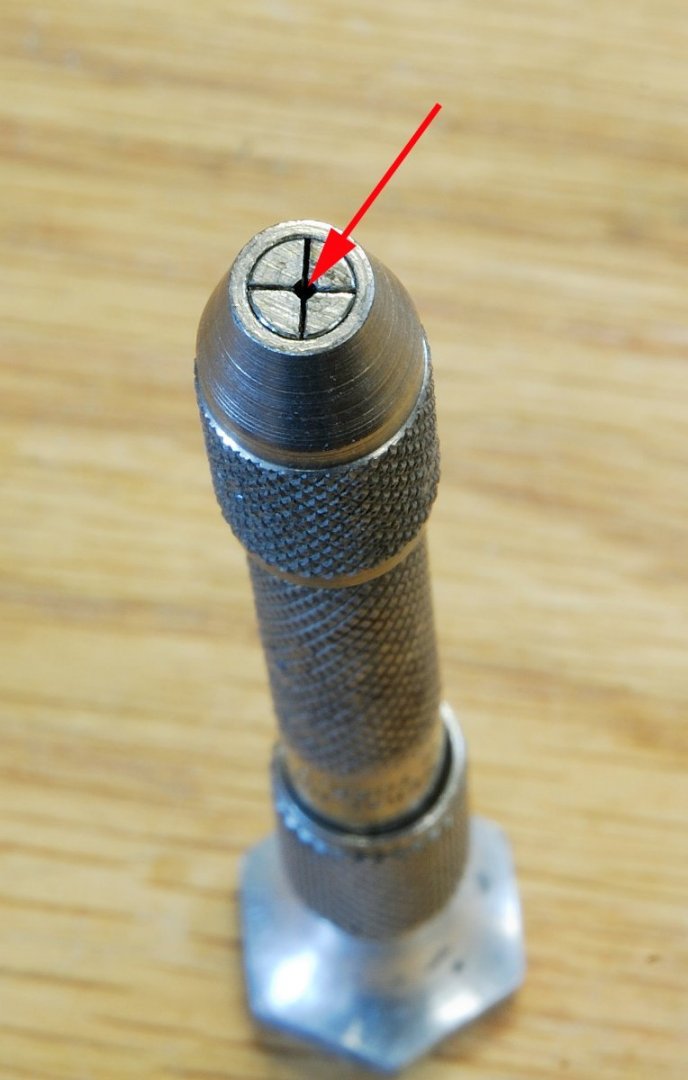

-
Mini lathe for mast making etc.
Dziadeczek replied to Charlie pal's topic in Masting, rigging and sails
If the bed of your lathe is too short for your masts/spars, turn them in sections, drill holes on both ends (also on the lathe) and insert short pegs there and connect them (wood glue) together. If both pieces are the same thickness, you won't see the connection. -
Waterways
Dziadeczek replied to Ron B's topic in Building, Framing, Planking and plating a ships hull and deck
This is how it looks like on the Polish sailing ship "Dar Młodzieży" (Gift of the Youth) - the green area on the right.
-
Wow! Attention to detail is unbelieveable! Very inspirational! Thanks!
- 589 replies
-
- 2
-
-
- le gros ventre
- cargo
- (and 1 more)
-
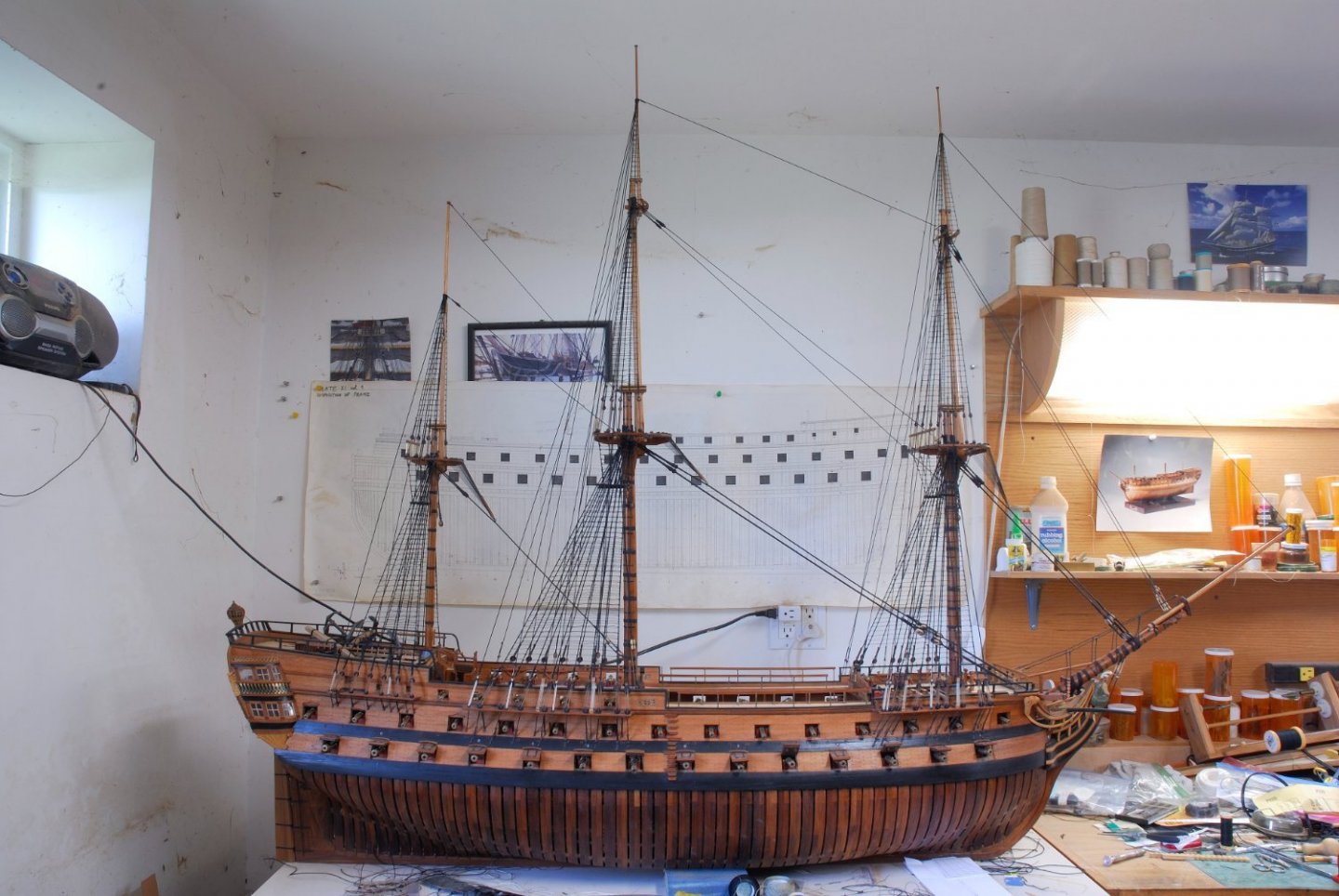
Is there a Boudriot's 74 Gun Ship in "kit" form???
Dziadeczek replied to Michael Scarborough's topic in Wood ship model kits
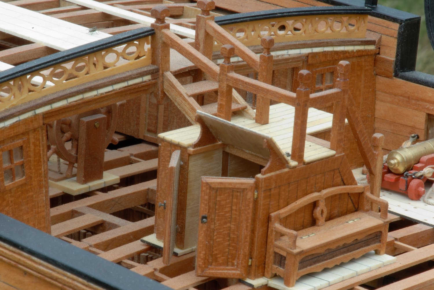
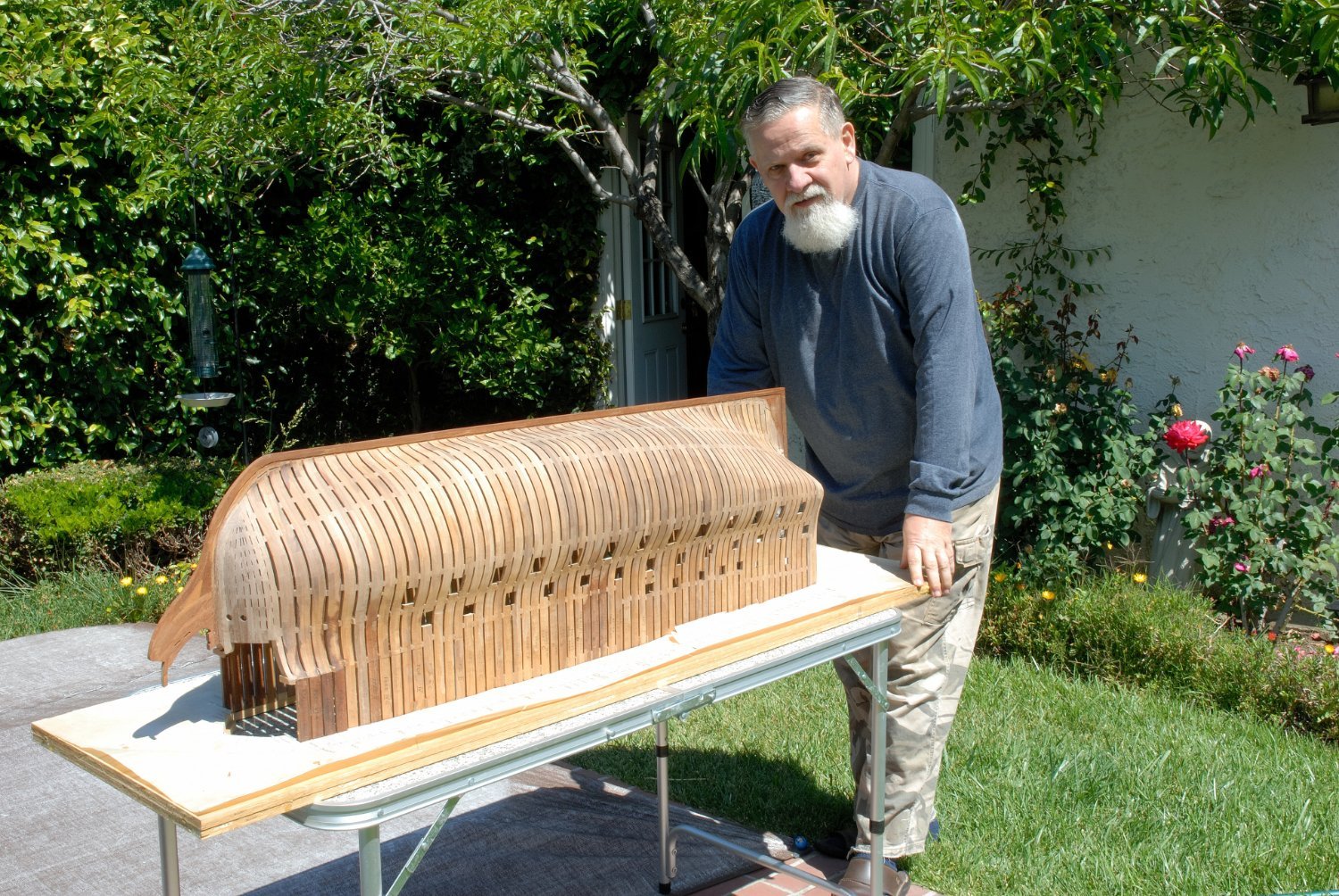
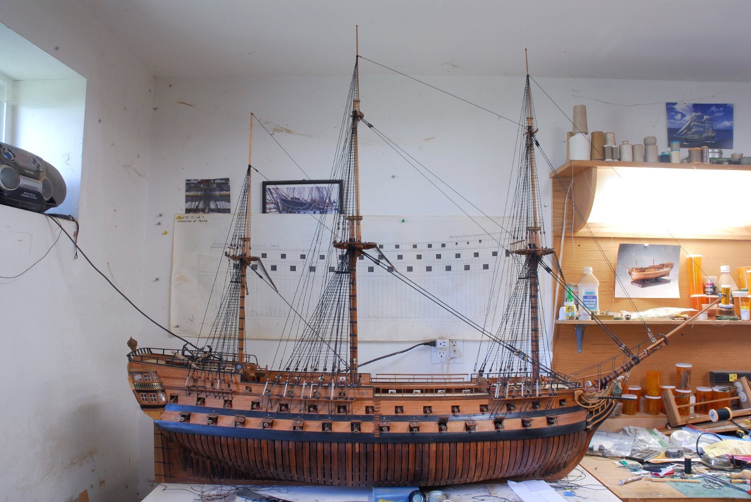
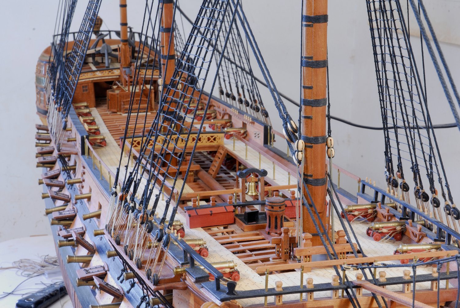
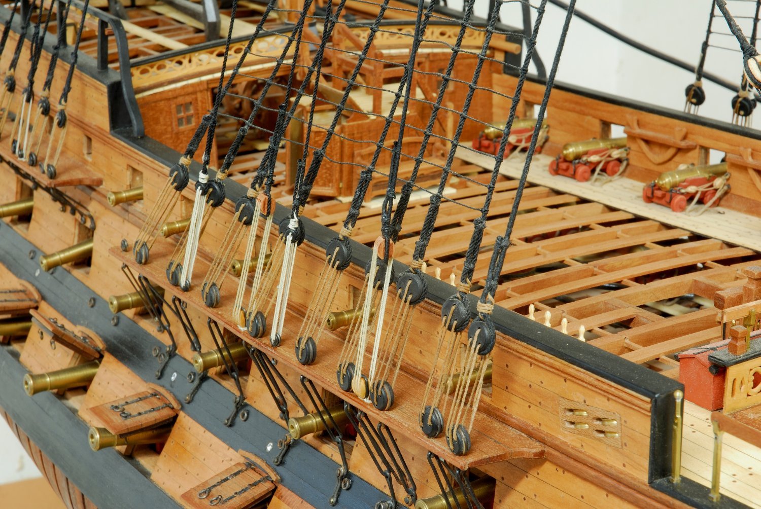
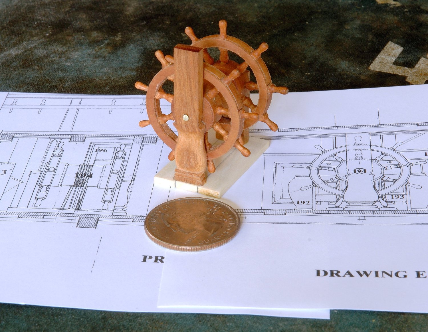
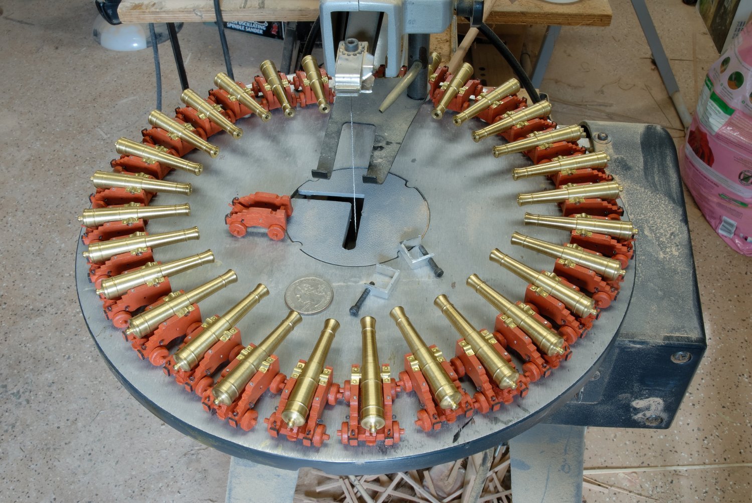
Hi Michael, I am scratchbuilding this exact model in the same 1:48 scale, following the books by J. Boudriot. It is a BIIIG puppy! If you want me to send you exact dimentions, I willl do it. Suffice it to say now, you would absolutely neccesarily need a separate space (a workshop of some kind) to build it. Kitchen table will not do it!!! And prepare yourself for YEARS of work! If you want to build it exactly like the books describe it, it is a monumental task! But, it is doable, especially now that the addendum (all frame profiles and the keel) is available from Ancre. When I started to build it, this addendum was not available, so I had to hand draw all missing profiles, since Boudriot only shows the so called, station frames (every 4th). It took a long time to draw all of them by hand, since I did not own a computer program. There is LOOOOTS of wood cutting, sanding and glueing, so several power tools are a must! Right now I am approaching the running rigging stage and sewing sails from thin muslin. Here is a handful of randomly selected pics of this model. Regards, Thomas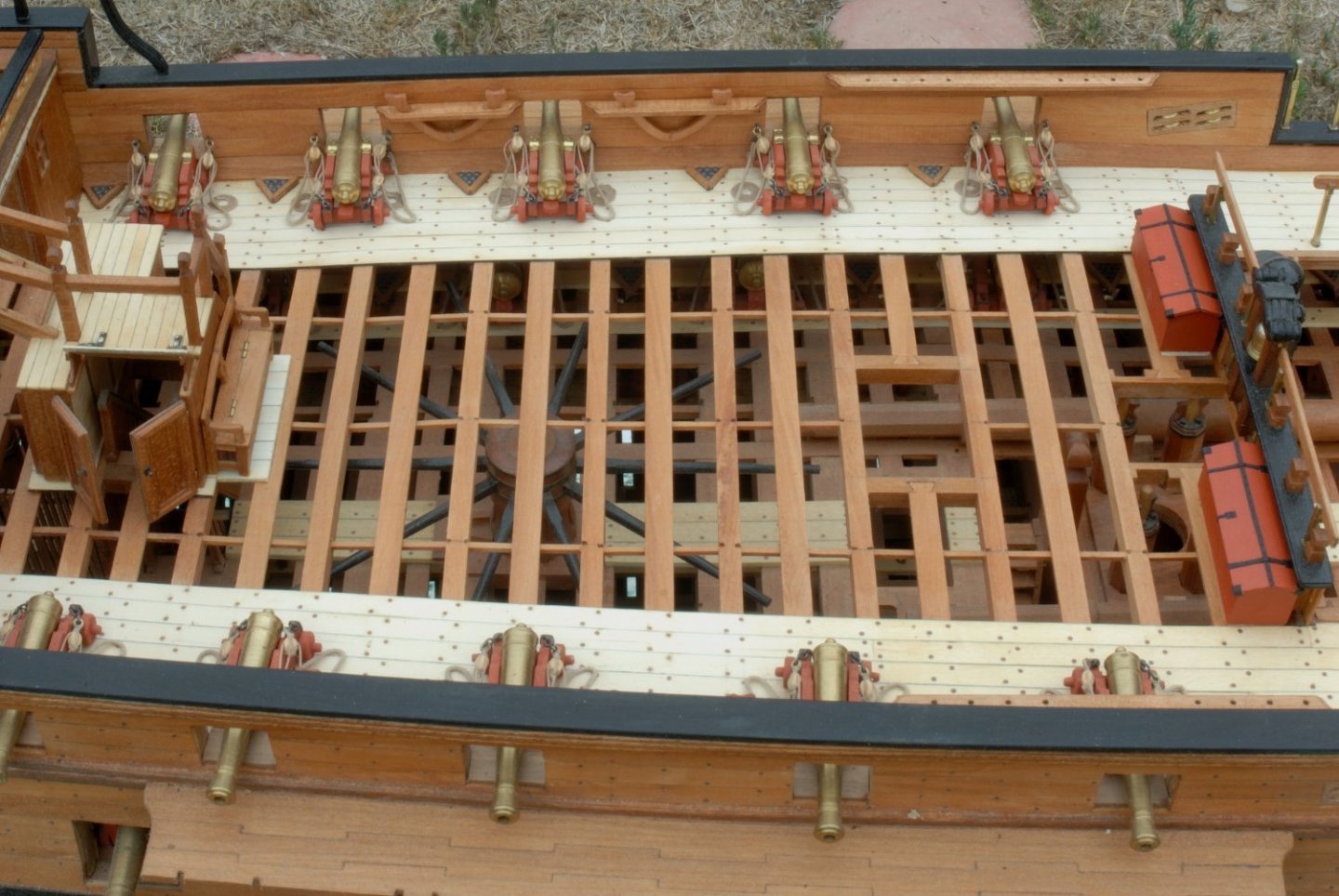


- 22 replies
-
- 13
-
-