


Bob Cleek
-
Posts
3,374 -
Joined
-
Last visited
Content Type
Profiles
Forums
Gallery
Events
Everything posted by Bob Cleek
-
Drafting
Bob Cleek replied to mangulator63's topic in CAD and 3D Modelling/Drafting Plans with Software
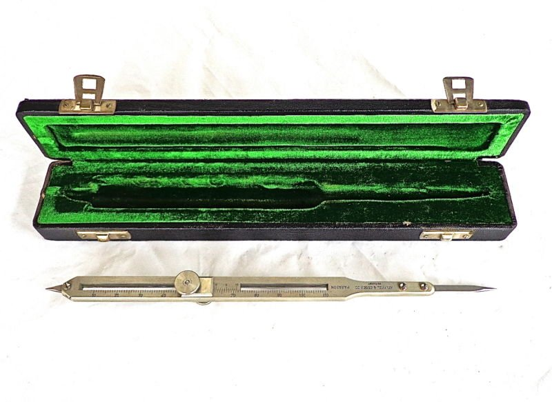
I was always on the "academic track" and ended up in law enforcement and then a lawyer, but I had the benefit of a father whose motto was "If you can't fix it, you don't deserve to own it." Well, back then, that was possible! He was an accountant who'd been born on my grandfather's cattle ranch in Montana and there really wasn't much he couldn't do. I learned woodworking and painting and darkroom photography and general "Mr. Fixit" skills from him. That wasn't the end of it. We lived in the SF Bay Area where there was a lot of education going on, and still is. He put me in a "gifted kid" electrical engineering program on Saturdays between fifth and eighth grades. I got to play with the first transistors and lasers and learn about electronics. My mother stuck my sister and I as "guinea pigs" in a university program for the Defense Department designing what became "language labs" for an entire summer. I still remember enough of that to find a bathroom in Moscow! I took typing in summer school as a freshman in high school and also took commercial art and a couple of semesters of mechanical drawing. Like a lot of modelers, I loved those courses and remember always being disappointed when the bell rang when I was in the middle of a project. I grew up appreciating tools and have amassed quite a collection over the years. I have to admit I've got more tools than time to use them. I never stopped using my manual drafting tools and, while I fiddled with CAD enough to appreciate it's advantages, I also came to quickly realize that I could do an awful lot with manual drafting tools faster and more efficiently than I could with CAD, in large measure because of the learning curve, but also because nobody's really been able to create a CAD program that will spring a fair curve as well as a wooden batten. The more I started drawing boat parts and plans, the more I found I needed some mechanical drawing tools that were going the way of the dodo bird. The first tool I decided to treat myself to was a planimeter. (Planimeters measure the surface area of irregular planes.) Not something I'd need to use all that often, but it made calculating vessel displacement tremendously easier and more accurate than the old "rules of thumb" techniques. I couldn't justify the cost of such a specialized measuring instrument, which I knew to be really expensive, until I realized that eBay was chock full of what used to be drafting instruments I had spent a lifetime lusting after and could never have justified spending the money they cost and they were practically giving them away. CAD was king and I'd discovered that "brief fleeting moment" between "obsolete" and "collectable." I started monitoring eBay daily and buying "nothing but the best" I could afford. I started researching and decided to specialize in Keuffel and Esser's "Paragon" line, which was their top of the line. I ended up with everything I could ever possibly find a use for, and then some. Hitting the market at the bottom was also a good investment because the "good stuff" has appreciated significantly as it became more scarce over the past decade or so. There's still some bargains that come up regularly on eBay and "users" are priced fairly, if you take the time to google up the old catalogs and identify the models that are desirable. Then there's always the thrill of the "bargains" that you come upon. It does the soul good to buy a complete cased set of Copenhagen ships' curves for $100 when they often go for three times that. I bought my mint-condition "old school" Hamilton 4X6' oak professional drafting table from a lady on Craigslist for seventy-five bucks! I did luck out getting into collecting before it became a "thing," though. I haven't seen anything but the standard ISO LEROY lettering templates for years now. They used to make them in all sorts of fonts, but those have apparently all been snatched up now. (You really need those old fashioned fonts to make a drawing look like it came out of the turn of the last century!) The big 10" K&E "universal" decimal proportional dividers, which are so handy for modeling, do still come up from time to time, and once in a while one in a "beater" case will go for less than a hundred bucks. I find a German silver "Paragon" set of drafting instruments, with their matching serial numbers like a prize Luger, resting in their green silk velvet French-fitted case is truly "jewelry" and I get a lot more use out of the drafting instruments than my buddy does out of his Luger collection! So, now that I've got mine and aren't worried about the competition, I'd encourage any modeler to "go for it." You don't have to go back to school to learn to draw with instruments. Just find an old high school mechanical drawing text book and start reading it. It's not rocket science... but tee-squares and slide rules did put the first men on the moon! And it's not just drawing plans, either. Check out this thread discussing the use of draftsmen's ruling pens for striking lines on models themselves.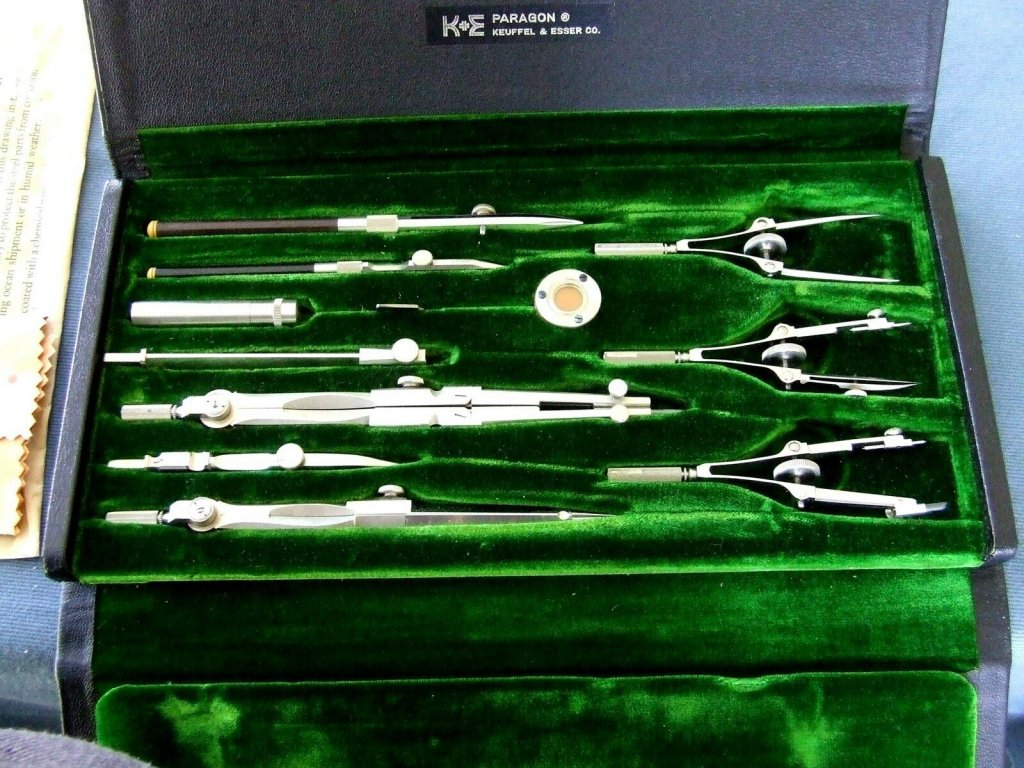
-
Wow! That's sweet! A cast iron mini-patternmaker's vise. That one's on my Christmas-to-me list! Thanks for the tip.
-
I once helped a master boatbuilder friend plank a whole 35' sharpie hull with the stuff. I loved it. He used it throughout the boat. I saved a few pieces for small projects of my own, but, sad to say, we threw the rest of the offcuts into the shop woodstove. We weren't thinking of it as modeling wood at the time! It's amazing stuff. There's whole stands of it standing dead in southern Alaska. It will last for almost a hundred years like that. It's range is moving due to climate change. Counterintuitively, due to global warming, the thinning winter snowpacks expose the roots to freezing which kills the tree. For this reason, it's under consideration for threatened or endangered status. One could probably harvest all they wanted up there, but it's not commercially viable getting it out of where it is. it makes you want to cry.
-
You can't go too far wrong for twenty-one bucks at Lowe's or the equivalent. https://www.lowes.com/pd/IRWIN-3-in-Cast-Iron-Clamp-on-Vise/1003168304?cm_mmc=shp-_-c-_-prd-_-tol-_-google-_-lia-_-106-_-clampsandvises-_-1003168304-_-0&placeholder=null&ds_rl=1286981&gclid=CjwKCAiArIH_BRB2EiwALfbH1CdIcRalCVC77wuXWEehSCPYcPtaMqs88v8737EcXADBIyQoZlRvhBoCRc8QAvD_BwE&gclsrc=aw.ds Bessey vacuum base vise at thirty bucks: https://www.amazon.com/Bessey-BVVB-Vacuum-Base-Vise/dp/B0057PUR88/ref=asc_df_B0057PUR88/?tag=hyprod-20&linkCode=df0&hvadid=312322422714&hvpos=&hvnetw=g&hvrand=1449783815818756065&hvpone=&hvptwo=&hvqmt=&hvdev=c&hvdvcmdl=&hvlocint=&hvlocphy=9032112&hvtargid=pla-435893379511&psc=1 Vost vacuum vise for twenty-five bucks at Home Depot: https://www.homedepot.com/p/Yost-2-75-in-Multi-Angle-Pivoting-Vacuum-Vise-V-275/205583839?source=shoppingads&locale=en-US&mtc=Shopping-B-F_D25T-G-D25T-25_1_HAND_TOOLS-Multi-NA-Feed-PLA-NA-NA-HandTools_PLA&cm_mmc=Shopping-B-F_D25T-G-D25T-25_1_HAND_TOOLS-Multi-NA-Feed-PLA-NA-NA-HandTools_PLA-71700000034127224-58700003933021546-92700031755124844&gclid=CjwKCAiArIH_BRB2EiwALfbH1BvgCGn1dN3GZDH5JwUpr035zxhEBxvih7Arp1UiAVLuoxi1oVqnihoCAH4QAvD_BwE&gclsrc=aw.ds Top quality Grobet Vacu Vise jeweler's vise for thiry-five bucks: https://www.penntoolco.com/grobet-usa-vacu-vise-with-swivel-base-58103/?matchtype=&network=g&device=c&keyword=&campaign=744568461&adgroup=pla-53104812259&gclid=CjwKCAiArIH_BRB2EiwALfbH1GDETTlOtNNzUF14rtxs9IEImktpr5p8qzDhKjKj83I0-lcarVGBUxoCpIYQAvD_BwE Proxxon suction base vise at forty-five bucks at Home Depot: https://www.homedepot.com/p/Proxxon-Precision-Vise-FMS-75-28602/203459683 I fail to see what's so special about Proxxon tools. They do have things others don't and sometimes they are available in areas where other options aren't, but they seem quite overpriced in my humble opinion. This appears to often be the case with any retailer who targets the hobbyist market.
-
If so, they'r'e taking a big chance, since the headstay is the most important, and most highly stressed, piece of standing rigging on the boat. The last place you want to screw in an eyebolt is the end-grain of the stem! It's a real invitation to rot in the fastener hole and the threads have little holding power in end-grain. One of the interesting features of these rather primitive, or should we say "basic," boats is how simply they are built and rigged. Their owners didn't have much to work with, but they found ways to do what needed to be done with simple elegance.
- 69 replies
-
- 2
-

-
- Galway hooker
- fishing
- (and 2 more)
-
Great job on such a relatively small scale model! One point which is worthy of mention is that you will likely find it necessary to shorten the length of your tiller. Characteristically, hookers have short tillers (which aren't helped by their notorious weather helm to which they owe their great weatherliness.) Tillers must be short to clear the mainsheet tackle which is attached to the middle, rather than the end of the boom with blocks secured to eyebolts secured to the sole framing. Commander Horner's lines published by Dixon Kemp and the earliest drawn lines I'm aware are extant, being done sometime in the late 1800's, show the characteristic bobbed tiller, although his single mainsheet tackle is not seen on many extant hookers, which predominantly extend the mainsheet purchase through separate blocks spread out on the boom and sole. You may also wish to note another characteristic detail: the headstay is not fastened to an eyebolt in the stemhead, but, rather, the stemhead is drilled with a number of holes to serve as fairleads for a lanyard and set up with a bullseye or deadeye on the stay, depending on the size of the boat. Similarly, the smaller boats frequently do not employ deadeyes on their shrouds, instead using a simple lashing. Usually, a hooker with single shrouds will use a simple lashing, while those with two shrouds will opt for deadeyes and lanyards. Headstay deadeye with frapped lanyards, as is common. Note the Dyneema / AmSteel / Spectra-type HMWPE rope used for the headstay. Some of the present-day hookers are using this super-strength rope for standing rigging.)
- 69 replies
-
- 5
-
-
- Galway hooker
- fishing
- (and 2 more)
-
Yes, but not as much of a mix as one might think. The hookers have been relatively unchanged for as long as anyone can remember, going back at least as far as the mid-1700's. A recent archaeological find turned up a well-preserved Basque fishing boat of the mid- 1600's which exhibits construction details identical to and previously unknown other than in Irish hookers and these similarities add support to the theory that the Irish hookers may have been derived from Iberian vessels. The west coast of Ireland was, until relatively recent times, very isolated. The very few roads inland were passable only in decent weather and only with horse and donkey-drawn carts until the 20th Century. The land was poor for farming and subsistence fishing was a primary protein source. They were dependent upon seaweed as a soil supplement for subsistence farming. The absence of trees caused peat to be used as fuel and the peat had to be shipped out to the offshore islands, along with everything else, giving the hookers one of their primary reasons for existence which continued commercially until the early 1970's. There still is no rail service. The area was as rural as rural could be and it was one of the few gaeltacht (predominantly "Irish speaking") areas in Ireland when the Republic was formed and remains so, but is dwindling with projections that Irish will cease to be a daily-spoken language anywhere within another ten years or so. It was this isolation, poverty, and "backwardness" that preserved the Irish hookers in a "time warp." Many of the existing "pre-revival" hookers are over a hundred years old, some even 150 years old, having been rebuilt many times over. In the mid-1800's, one hooker building family, the Reneys, seem to have slightly sharpened the forefoot entry, while retaining the rounded "apple bows" higher up. One Reney emigrated to Boston where he eventually opened a boatyard and built Galway hookers in the "Raney style" for the Irish fishermen settling there. (Chapelle calls these "Boston hookers" and claims they were a modified evolution of the Irish hookers, but there is no indication in the history known now that would indicate there was any change in the Boston hookers from the Irish originals built by the same boatbuilder, nor any reason under the sun why there would need to be.)
- 69 replies
-
- 4
-
-
- Galway hooker
- fishing
- (and 2 more)
-
Lucky score! As you may have noticed, they aren't easy to come by and they certainly aren't inexpensive!
- 69 replies
-
- 3
-
-
- Galway hooker
- fishing
- (and 2 more)
-
The original post was titled "chisels," but his last comments asked for input on buying lathes and mills. Cleek's Law No. 6: "Any discussion thread addressing any tool on internet modeling sites will inevitably devolve to a mention of lathes."
-
I lived for many years without a lathe or mill before I acquired a good used 12X42" Atlas lathe with extensive tooling for an amazing price. It has a milling attachment and I've never needed a bigger mill for what I do. I also have a Unimat SL modeler's lathe which converts to a mill. There are a very few things that cannot be done without them, but they aren't things that need doing all that often. You can do milling on a lathe with the right tooling. You can't do turning on a mill as you can on a lathe. In the world of wooden ship modeling, you don't need a lathe or a mill, but if you want to seriously scratch-build in wood, you do want to have accurate miniature wood-working power tools and that means "the trifecta:" the Byrnes table saw, thickness sander and disk sander, plus a decent drill press and a shop vacuum. Next, you'll want a decent scroll saw, not a cheapo model. If you want to mill your own wood from the tree, you'll need a 14" band saw. Only then should you start lusting after a lathe or a mill. Focusing on acquiring the table saw and thickness sander first is essential these days. Pre-milled stock is getting harder and harder to find and I, for one, am convinced it will soon be unobtainable at a price any sane person would want to spend. The wood you can get for nothing out of an old apple or holly tree and the like will quickly pay for that saw and thickness sander right out of the gate. One thing that can't be said too often or too loudly to the uninitiated: don't underestimate the cost of the tooling essential to use machine tools like lathes and mills. In order to get the use most expect from their lathes and mills, you will have to spend at least as much on tooling as you did on the lathe or mill itself. Even the fancy package deals that advertise all the "comes with" tooling provide only the most basic of tooling and often not the best quality at that. For this reason, the Chinese Sieg 7X lathes, preferably from a vendor that will guarantee quality control (e.g. Little Machine Shop, Grizzly, etc.) are probably your best bet in terms of bang for your buck because, since there are so many of them in circulation, their tooling is more available and less expensive. Taig and Sherline are great machines, but they are much lighter than the Siegs and so more limited in their abilities and the cost of their tooling is wicked expensive. (Proxxon has its fans, but I find their tools priced far higher than their quality warrants.) You really don't want to spend the $1,500 to buy even an entry-level lathe or mill and their essential tooling that is going to sit on your shelf 99% of the time while you try to scratch build without a Byrnes table saw, thickness sander and disk sander.
-
Most people find using a much finer sanding grit than 150 for final finishing work, usually at least 320, and do not attempt to finish coat open pored wood species like walnut without first using a filler. That produces a perfectly smooth "furniture grade" finish, if that is what one is shooting for.
-
I believe you are actually referring to coverning boards, not margin planks. Covering boards are simply as long as the wood stock available to the builders at the time. Because they curve the length of the vessel, wood of sufficient width doesn't exist. As you accurately mentioned, covering board joints may be butted or scarfed, generally depending on the "fit and finish" of the vessel. Joints aren't caulked. Their faying surfaces are payed with bedding compound and they are fastened together using butt blocks, scarf wedges, or whatever other method is appropriate to the connection method used. Those seams should be barely visible under any circumstances, although, in the case of a butt, the butt would usually be beveled to form a caulking seam and the seam caulked and payed in the same manner as the adjoining deck seams.
-
As Jon's photos accurately depict, metal fasteners (often in this size construction galvanized square-cut boat nails are countersunk and plugged with a wooden plug of the same species of wood set into the planking with the plug's grain running in the same direction as the plank's grain (to prevent the plug working loose as would tend to occur when the wood and the plug otherwise swelled in different directions.) The purpose of the plugs is to minimize corrosion and to permit sanding the deck fair and clean now and again ("holystoning.") Plank fastening is done with wooden fasteners ("trunnels.") Trunnels have their grain running the length of the trunnel and are often of a different species, frequently locust in the time period discussed here. Given that the end grain of a trunnel is exposed at the plank surface and often is of a darker colored wood, they can appear somewhat more visible than the fastening plugs, which show their face grain at the surface and are nearly invisible. In "real life," the hull and deck planking will be painted an opaque color, or oiled, which eventually results in a near-black color, so the trunnels will not be visible unless the hull planking is bare, as it would be when the vessel was under construction. These facts apply to appearances "up close" on the prototype vessel. A model depicts what the viewer would see from a scale distance. The scale distance is the distance a viewer would have to stand away from the prototype vessel to see the same scope of the vessel he sees when viewing the model. In other words, "How far back to you have to stand to see the whole vessel from stem to stern?" At scale distance, detail is lost (and colors tend to fade with gloss nowhere to be seen.) At scale distance deck fastener plugs are invisible and black deck seam stopping barely visible. At scale distance, even bare hull planking trunnels will be barely visible, if at all. Exaggerated depictions of fastenings, plugs, treenails, and deck seam stopping, not to mention over-scale coppering tacks and plates, are affectations embraced by some modelers for reasons I don't entirely understand. This is particularly so in cases where plugs and trunnels are colored black to accentuate their appearance, an occurrence that never existed on any prototype vessel anytime or anywhere. Where real pegging is employed to fasten model planks to frames, the same wood material should be used and the pegs faired to the planking surface if the wood is to be left unpainted. That practice will depict the scale trunnels accurately as to color and they will be barely visible. When such practice is followed, it is essential that all pegs are placed in the same positions as would be the case with the prototype vessel, i.e. at proper scale distance from each other running over beams and frames at locations accurate to the original vessel. Note that the second picture you have posted above is of a modern era faux laid deck without fasteners or plugs, being instead laid down in adhesive, frequently epoxy, as a veneer over a substrate, frequently metal, plywood, or fiberglass, and not relevant at all to the present discussion of traditional wood construction practices. Particularly, the layout of the decking pieces around the base of the winches and fittings is a pure fantasy which glaringly clashes with what appears to be an otherwise beautifully done traditional-looking yacht. Such oddities have no place on a traditionally built, or built-to-appear-traditional, vessel and, where encountered, are the mark of an owner with more money than knowledge.
-
Jim Byrnes Thickness Sander
Bob Cleek replied to Roger Pellett's topic in Modeling tools and Workshop Equipment
Being as sandpaper was almost certainly not available in their place and time, I'd say scraping was a safe bet. -
Jim Byrnes Thickness Sander
Bob Cleek replied to Roger Pellett's topic in Modeling tools and Workshop Equipment
This seemed to make sense, but I've only ever been concerned about "tooth" in adhesive applications when using epoxy adhesives. When a good epoxy bond is of paramount importance, I use a preliminary application of penetrating epoxy sealer (Smith's "CPES") and then the epoxy adhesive, not clamped too tightly to avoid "joint starvation." (The penetrating epoxy soaks into the wood and the epoxy adhesive then creates a molecular bond with the penetrating epoxy so long as the two are joined within 48 to 72 hours. (See: tech data at: http://www.smithandcompany.org/) I've used a lot of PVA in woodworking applications and, generally speaking, I'm a "planer," not a "sander." I was taught that "the tighter the joint, the stronger the joint." I've never given a second thought to joining smoothly planed surfaces with PVA and I've joined a lot of them without ever noticing any problem. This got me thinking. Well, not thinking, as much as googling, and at the risk of falling victim to the comedy of errors known as the internet, I looked it up and found an interesting and credible answer in an excerpt from Popular Woodworking quoting the Senior Technical Specialist for Franklin International, the makers of Titebond PVA adhesives: "Our work has shown that a smooth surface will always have higher strength than a rough surface. Two-hundred grit or higher sanding to get flat or tight-fitting joints works well." The Titebond tech expert gives one caveat: PVA will not bond well to burnished wood. While I doubt wood is intentionally burnished by many modelers, burnishing may inadvertently occur when wood is sanded with dull sandpaper and when sanding dust builds up between the abrasive sheet and the worked surface, especially with high speed power sanders, or when dull circular saw blades and other rotary cutting tools rub against wood surfaces, even to the point of burning. Titebond's expert says wood can be tested for burnishing by placing a drop of water on the surface. If he water soaks into the wood, it's not burnished. If water doesn't soak into the surface readily, the bonding surface must be sanded enough to remove the burnished surface. I have little or no experience with laser-cut parts, but I wonder if the heat to which laser-cut surfaces are exposed may create a burnishing effect which might extend to some depth below the "char" into the wood. Perhaps those using laser-cut parts might do the "water drop test" and report back on this question. The article can be found at https://www.popularwoodworking.com/techniques/best-wood-glue-surface-smooth-or-rough/ and is quite informative. What I found of particular interest upon reflection was the fact that the strength of a PVA glue line is in great measure affected by high clamping pressure. This I knew, but never gave any thought to in the context of modeling. The general woodworking maxim is "except when using epoxy adhesives, glue joints should be clamped as tightly as possible until cured." The way I employ clamping in most modeling applications, when a part is clamped at all, is more to hold the part in place than to apply strong clamping pressure. I do try to mechanically fasten parts as much as possible, using pins and pegs, and I'm even more convinced now of the merit of that practice than before. In so many modeling applications, it's just not possible to clamp a part strongly because of its shape, location, the strength of the part itself, or a combination of the above. It would appear that without strong clamping pressure, PVA may not be any better than any other kind of "stickum." As the saying goes, "Your mileage may vary." but I'm buying what Titebond's in-house senior tech says. -
Model Photography/Scheimpflug Principle
Bob Cleek replied to Charles Green's topic in Modeling tools and Workshop Equipment
I'll see you your Cannons and raise you my Nikon F Photomic head system and later Nikon 35mm's. Then there's the Leica screw mount stuff I inherited from a friend. The whole cased system, less the IIIg body. My 120 format cut and roll film cameras are gone, but I still have the darkroom equipment for them and a 70+ year old Solar bellows enlarger. I wish I knew some kid that wanted to get into doing their own B/W processing. I can't bring myself to donate it all to Goodwill and I'm too lazy to off it on eBay. I keep telling myself film is going to come back like vinyl LP's are. -
You're "doing it the hard way" and will continue to run into the same problem as you progress in your framing because there's nothing to hold the frames in place. Your solution at the moment shows you are thinking, though. That's the way to solve the problem, but doing it piecemeal as you are without the entire structure held together will probably result in a never-ending game of "frame whack-a-mole" as one moves out of alignment as soon as another is set up. There's lots of ways to address the issue. One of the more popular is using a building frame from the beginning. one approach is the "Hahn menthod," in which the hull framing is initially set up upside down (keel up) with a base that has provision for holding the frame heads in place. See: https://www.dlumberyard.com/hahn-PART4.html and http://modelshipworldforum.com/resources/Framing_and_Planking/HahnMethodnew.pdf Another method achieves the same result the same way, but the structure is assembled keel down on a baseboard with the notched frame holding the frame heads raised from the baseboard on sections of threaded rod. This method has the advantage of allowing the installation of internal structural members, particularly keelsons, clamps, shelves, and beams prior to planking. Another method is the "basket method," which can be found described in the seminal works of Charles Davis and Harold Underhill. If following the full-size practice of boat building, as opposed to ship building, and is more suited to modeling. This method is similar to what you are attempting right now, except that the battens are extended the length of the hull on both sided, bent over a few widely spaced molds or frames, if your frames are strong enough. (Often, all that is required is a mold at the broadest beam point and one or two forward and aft of that. Your transom and/or stern post forms the landing for the battens aft and the stem rabbet the landing forward. If your molds are accurately set up, the battens (pieces of strip wood the length of the model at various heights) are temporarily fastened to the molds (just as you have done with wire ties) and these battens form a "basket" to hold the frames in position. (The frames in the way of the molds are set up after the rest of the hull is planked up.) Once the framing is complete, planking commences with the wales first and then the rest of the planking fastened to the frames. As the planking progresses, the battens are removed and replaced with planking until all the battens are gone. Then the molds are removed and the remaining frames placed where the molds had been. The below photos of a half-model displayed on a board demonstrate the technique, although in this instance the battens are permanently fastened on what appear to actually be solid molds or "bulkheads," rather than actual frames, and the opening permits the interior construction to be seen when the model is displayed. This method is also a time-saver when it comes to planking if you run your battens such that they define the run of your planking. In that way, they save the intermediate step of lining out your planking using tape or string. The battens are already there doing that for you. Planking is much easier off of a building board (IMHO) and the battens and previously hung plank maintains a very rigid structure throughout the planking process. http://www.skipjackmarinegallery.com/mm5/graphics/00000001/half-hull-model-ship-construction-frigate-sloop-of-war-vintage-antique-18069-starboard-side-view.jpg http://www.skipjackmarinegallery.com/mm5/graphics/00000001/half-hull-model-ship-construction-frigate-sloop-of-war-vintage-antique-18069-starboard-bow-view.jpg http://www.skipjackmarinegallery.com/mm5/graphics/00000001/half-hull-model-ship-construction-frigate-sloop-of-war-vintage-antique-18069-stern-view.jpg http://www.skipjackmarinegallery.com/mm5/graphics/00000001/half-hull-model-ship-construction-frigate-sloop-of-war-vintage-antique-18069-rib-interior-view.jpg http://www.skipjackmarinegallery.com/plank-on-frame-half-hull-model-of-ship-of-war.html
-
Yeah, as the sayings go, in full-size boatbuilding, "You can never have enough clamps." and in ship modeling, "You can never have enough research!." at some point, you just have to start building. You're way ahead of me on that score. I enjoy the research as much as the building, though.
- 69 replies
-
- 3
-
-
- Galway hooker
- fishing
- (and 2 more)
-
You are correct. The "Irish," "Galway" or "Connemara Hooker" is a type of boat and those are broad generic terms for the type. Locally, however, they are referred to by their size classes, Bad mor ("bad more"), leathwad ("la-wad"), gleoiteog ("glow-chug"), and pucan ("poo-con.") They were never built to plans and each has it's own unique details, but what they have in common is their general shape, rig, and construction details. The only accurate plans in the modern form are those taken by researchers from existing tradtionally-built vessels. Joe Murphy has done a set, as has Richard Scott, who's now deceased. If you can find a used copy of Scott's The Galway Hookers at a price you can stomach for a small paperback, I'd urge you to get it because there's a wealth of information in it. Unfortunately, the drawings for two hookers in Scott's books are printed very small and would have to be enlarged and then redrawn to get much use from them for building anything. The Galway Hooker Association has a good website that's worth keeping an eye on. https://www.galwayhookers.ie/ Someone in the association may be able to connect you with a source of accurate traditional hooker plans, as this association has been involved in building new hookers in recent decades but, as I mentioned, they never were built to plans, so they may be doing it the old fashioned way, since the "hooker revival" is all about the revitalization of Irish culture and language following centuries of British colonial oppression. Most valuable to you would be a copy of a small book called The Galway Hooker (Huiceir na Gaillimhe in Irish, it's text is in both English and Irish on facing pages.) It is one of a three volume set called Shipwrights (Na Saora Bad), the others being on types of currachs. This book is self-published by Cian de Buitlear. In a pocket within the book is a set of 3 drawings of complete plans, 16 inches x 24 inches at 1/2 inch to the foot scale, with a narrated step by step DVD video of Joe Murphy's building of the gleoiteog, Star of the West, from start to launch. It was published in 2005. I couldn't find it anywhere online. You might want to contact the publisher and see if you can get a copy: Cian de Buitlear, Sruthan, An Cheathru Rua, Co Na Gaillimhe, Ireland. Telephone number: 087 2557 444. Email: ciandebuitlear@eircom.net This is the only available set of accurate construction plans for an Irish hooker to be found published anywhere. I did notice that there is a new "coffee table" pictorial book out, Huiceiri / Galway Hookers which is described as "mentioning the main building features of this craft, but is probably more "boat porn" than a building manual, although there's nothing wrong with boat porn. At $25 euros, it wouldn't break the bank, but I do have to email them to inquire if it is bilingual or not. ("Huiceiri" means "Hookers" in Irish.) Check it out if you want: https://www.seanchaieditions.com/our-publications/books/huiceiri-galway-hookers
- 69 replies
-
- 4
-
-
- Galway hooker
- fishing
- (and 2 more)
-
Thickness Sander questions
Bob Cleek replied to Ron Burns's topic in Modeling tools and Workshop Equipment
Yes, on all counts. i can't imagine running one without a good vacuum pickup. (My Byrnes sander has and excellent one.) Plain sandpaper isn't really the best option. What is the best is the same heavy cloth-backed abrasive material that belt sander belts are made of. -
Very clever approach to planking first and removing the bulkheads! Your hull has a nice shape. I'm not sure to what extent you are planning to display your framing, but you might want to take a closer look at the framing detail. While there is one set of construction drawings on the internet done by Nick Branson (https://www.boatdesign.net/threads/26ft-galway-hooker-pucan-to-build.40781/) which shows a simple half-lap scarf to join futtocks to create a single frame, these plans have been "modernized" and do not employ the traditional, and very distinctive, framing and other construction methods and scantlings of the traditional Irish hookers. There are no steamed frames in a traditionally-built Irish hooker. Hookers have sawn frames.The molded depth of the frames is perhaps twice their sided width. Peculiarly, the futtocks are staggered. There is a floor timber (no keelson) from which which three overlapping futtocks rise, alternating to one side or the other. Their ends are cut at an angle and fastened with a bolt and four nails holding them where they overlap. These overlaps are lined up in a fair line fore and aft. Frames far forward and far aft are canted and, where their shape allows in the bow, may be sawn from a single timber. One might overlook this detail for the sake of "artistic license," but as it is so distinctive a construction feature, and one that reaches back in a straight line perhaps as much as 300 or more years to its likely Basque antecedents, you may wish to depict this feature accurately in your model. This series of three videos contains a fair amount of detail on the construction of the traditional hooker. You can hit "pause" when you see a hooker in frame and study how the futtocks are placed. https://www.youtube.com/watch?v=s3R4ZdW3trY
- 69 replies
-
- 4
-
-
- Galway hooker
- fishing
- (and 2 more)
-
Well, I'm assuming if one is using a solvent-based coating at all, they will also have to buy the solvent as well, for cleaning purposes, at least.
-
"Satin Wipe-on Poly" is nothing more than thinned polyurethane coating. You are paying a lot of money for thinner! I've read that it isn't sold in Europe, where people simply thin the "full strength" polyurethane and achieve the same result. The same result can be achieved with a 50-50 mixture of linseed oil and turpentine. If you want faster drying, which isn't that much of a factor with thin coatings, you can add a bit of Japan dryer to the mix, or use "boiled" linseed oil, which isn't boiled at all, but simply has the Japan dryer added already. Oops! I forgot to mention for "the youngsters" who may not be aware in this day and age, that rags and such soaked in linseed oil should always be properly hung to dry outdoors and disposed of in a covered metal can. This prevents spontaneous combustion which can occur hours after throwing them out.