Bob Cleek
-
Posts
3,374 -
Joined
-
Last visited
Content Type
Profiles
Forums
Gallery
Events
Everything posted by Bob Cleek
-
Gaff sails and backstay rigging rules
Bob Cleek replied to Michelnou's topic in Masting, rigging and sails
Well, yeah, but you'd expect that with a Polish crew! (I hope I didn't offend anyone with a Polish joke!) -
And then there's white (clear) shellac. A touch with a loaded paintbrush wicks quickly into the knot or line and dries very fast. It's invisible when dry. Line can be shaped as desired while it is drying. It cleans up easily with denatured alcohol and, most importantly, can be reversed after drying by applying alcohol again to the shellac, which will then dissolve, as before. Oh, and did i mention, it's the cheapest of all options and also serves as a great wood sealer and finish. Your mileage may vary, of course.
-
Sometimes unusual arrangements get called whatever the master wants to call them. On the Thomas W. Lawson, the only seven-masted schooner ever built, they never could make up their minds what the names of the seven sails were. Somewhere on the internet there's a chart of all the names they were called at different times under different masters. (Nautical trivia quiz answer: fore, main, mizzen, spanker, jigger, driver, and pusher.) I'd call that sail a jib-headed mainsail. The head isn't cut far enough down the leech to make it a leg-o-mutton, I'd think. It's an interesting sail. Note that the leech is cut away from the mast at the head and there's a short yard at the head that's on a bridle to the block on the crane, which prevents the fouling of the halyard block against the mast. Above the jib-headed main, was flown a main topsail with its clew led to the end of the main boom, a once-common sail now rarely encountered. Danged If I know if it had a particular name besides a main topsail. Turner employed main topsails clewed to the boom in many of his brigantines. A picture or two is worth a thousand words: A contemporary painting of Matson's Turner-built Lurline flying a boom-clewed main topsail. Photo of Lurline with main topsail brailed aloft as shown in the photo in the original post. Photos of Matthew W. Turner, a recently-built sail-training vessel designed to meet current USCG passenger regulations, but designed based on Turner-built brigantines and flying her main topsail. Interestingly, it appears vessels with this arrangement flew their ensigns from the mainmast truck.
- 8 replies
-
- 3
-

-
- Brigantine
- 1800s
- (and 3 more)
-
I have found the best, and most economical source of glass for model cases is a picture-framing shop. (I go to "Michael's," a crafts store chain in the US, which has a framing department.) Give them the exact size of the panes you want and tell them they have to be exactly cut. What you want, and they will have, is UV-filtered art framing glass. This glass has an ultra-violet light inhibiting feature that reduces damage from UV exposure. (Which isn't to say you can then display the model in front of a sunny window!) Ordinary window glaziers aren't ordinarily used to dealing with assembling fine furniture pieces like ship model cases.
-
Wood filler?
Bob Cleek replied to Phalpenny's topic in Building, Framing, Planking and plating a ships hull and deck
Well, there are "cracks," and then there are crevasses! But for cracks, I sometimes find a furniture finisher's crayon useful. These wax "filler sticks" or "crayons" come in a wide range of wood colors and can be purchased individually or in sets with a range of color. All you do is warm the wax in your hand to soften it a bit and apply to the crack and then rub away the excess. Fine furniture finishers use them to fill open joints and nicks and dings, as do gunsmiths on banged up gunstocks. They cost around three bucks apiece. Color chart: https://woodrepairproducts.com/product/fil-stiks/?gclid=Cj0KCQiAwf39BRCCARIsALXWETxVSo6lB0Guzfus1DrsLNcS6EnG11mDoXB0vhFS4_SFn8DkaBctn1kaAvsZEALw_wcB -
Gaff sails and backstay rigging rules
Bob Cleek replied to Michelnou's topic in Masting, rigging and sails
Nor the famed Danish spidsgatter racers with their uncommonly high and large rigs and carry no backstays at all ! -
I'm not sure of your question. That's a relatively easily planked bow shape. It appears the model builders pictured simply ran their plank ends forward of the stem line and then cut off the excess to the bow rabet. The practice then is to glue a strip of wood bent to the leading edge of the bow and sand it to a fair rounded leading edge. As for planking, read up on what Chuck Passaro has shared about planking. It's the best tutorial on the subject I know of. https://modelshipworld.com/forum/98-planking-downloads-and-tutorials-and-videos/ As the original vessel hull was built of steel, I doubt you will be finishing the wooden model planking bright, so the good news is that fairing compound will cover a multitude of planking errors as long as you get the basic shape right.
-
Adding to Eberhard and Dr.PR's comments, this discussion reminds me of something my late boatbuilding mentor, a older fellow who'd been one of the last to have gone through a traditional trade apprenticeship and had run a boatyard of his own for perhaps fifty years, said to me on the subject: "A house framing carpenter cuts to the nearest quarter inch, a finish carpenter cuts to the nearest thirty-second of an inch, and a boat builder cuts to the nearest boat." His point was that it isn't the measurements that matter, but rather the fit of the piece to the ones next to it, so forget about the dimensions on the plans and pay attention to what you are fitting together. Any sort of ship or boat plans, at least until the advent of CAD, are never absolutely accurate. What they are, really, is simply "scaled plans for drawing full scale plans." You can't draw a scale line fine enough, even at 1:48. Back in the day, they'd draw the lines of a 150' ship on a six or seven foot long piece of drafting vellum and the scale lines drawn would still be so wide if blown up to full scale that you couldn't take accurate measurements from the plans. While at modeling scales, the problem isn't as great, how often do we see plans drawn to 1:48, even? The rule in full size engineering is always that measurements are never to be taken from the drawings, but rather must be taken from the notation of the distance on the drawing. In modeling, we can cheat somewhat, but only if we "build to the boat" and not to the plans. What the pre-CAD draftsmen did was to take up a "table of offsets" from the drawings with dividers and read the distances from scales, knowing that no matter how carefully they placed their divider points on the center of the line, the table of offsets would never be perfectly accurate. Indeed, if the offsets for a 150' ship were accurate to within an inch or two, they were quite good. The purpose of the table of offsets was to enable the loftsman to loft the patterns for the ship full size. The loftsman takes the table of offsets and the lines drawings and uses these to draw the vessel full size on the lofting floor. When doing so, the loftsman uses battens to spring fair curves, using the offsets as a guide, but the offset points are rarely all on the fair curve sprung with the batten. (There are many tricks to the loftsman's trade. In "fairing the lines" from the draftsman's offsets, the loftsman uses the "diagonals" to test the accuracy of the lofting, for example. Further discussion of this is beyond the scope of this post, but for those interested, Lofting, by Alan Vaitses is highly recommended.) The loftsman trusts the batten, not the draftsman's offset measurements to develop the full size patterns for the shape-defining parts of the ship. Only once in a while, when there are a number of identical vessels to be built, will you get lucky and find that a loftsman has generated a corrected table of offsets from the full size lofting that are "tighter than a gnat's ***." In this case, there will usually be a notation on the table of offsets like "Corrected offsets." or "Offsets as lofted." Otherwise, the offsets will have to be "faired" on the loft floor. The loftsman's full size patterns were usually only those essential to get the vessel "in frame." From there, the "wood butchers" "built to the ship," not to the plans. They'd set up a few basic frames, sometimes as few as as a midship frame at the widest beam and a couple forward and aft of that, plus a stem and transom. Then they'd tack battens sprung across the faces of these frames and the resulting "basket" defined the shape of all the frames in between. In such fashion, a fair hull would be constructed. This is sort of the way planked models used to be built, although once in a while, an author would draw up a full set of frames and publish them for modelers to use, as we see in the old modeling books by Davis and his contemporaries. Today, CAD makes it possible, in theory, at least, to generate far more accurate drawings and it seems modelers are seduced by CAD and then find themselves sucked into believing they have to become micro-machinists using extremely accurate (and expensive) machines with DRO, or even CNC, to turn out parts accurate to .0005 if they want to build a good model, even from a kit, but this isn't so. "If it looks right, it is right." was the old time ship builder's maxim and it serves the modeler as well in miniature as it did the old timers working in full size. The old timers didn't have to worry about cutting each side perfectly square and to exact size when making a box. They just cut half of the sides a bit large and when the box was built, they planed the overhangs on the edges to fit, yielding a perfectly jointed cube. I'm not knocking CNC, for it certainly has it's place. (We wouldn't have IKEA knock-down furniture without it!) For building one-off models, though, the old fashioned measuring tools are more than sufficient and often much less expensive, not to mention a joy to own and even collect. Our goal is to create a compelling impression of reality in miniature. That doesn't always mean NASA-level tolerances in our measurements. (Even at that, John Glenn orbited the earth in a rocket ship designed with slide rules!) Sometimes, even slight deviations from exact scaling, such a a smidgen smaller rigging lines, can actually produce a more compelling impression of reality than perfectly sized ones, and that's when modeling becomes an art and not just a craft. So as the man says, "Don't sweat the small stuff."
-
Compound Plank Bending
Bob Cleek replied to Neil10's topic in Building, Framing, Planking and plating a ships hull and deck
Dry heat is all you need. There is no need, nor point to using, steam or moisture of any kind when bending wood unless you have to, and that's probably almost never when modeling. The steam or other moisture only serves the purpose of transmitting the heat to the wood. Given the size of the pieces in full size boat building, steaming in a steam box is a good way to heat the wood through and through in order to soften the lignin in the wood which is what it is all about. Even so, dry heat is also used where possible, to avoid the hassles involved in dealing with steam and moisture. (The gondola builders of Venice use open fires to heat their planks for bending.) But why get wet if you don't have to and when you can put the heat exactly where you want it and easily apply more as you need it when bending the piece? A clothes iron as Chuck uses works very well for heating strip wood to bend it on the flat ("edge setting" in boat building parlance.) and you don't have to mess with steam or boiling water which risks burns and wets the wood which then requires drying time and, if moisture remains, often makes gluing difficult. Actually, if you use PVA adhesive to glue your planks in place, applying heat with an iron on the outside of the plank at each glued frame or bulkhead will dry the PVA, effecting a much faster setting time. To obtain curves in another direction (not exactly a "compound curve," which something different than what you are talking about here) a clothes iron can be used, but a heated, curved former is probably more effective. Use the forum search engine. There are posts on ingenious ways to do this. Some use tin cans heated on the inside with a propane torch as a former. Some use a pipe heated with a torch on the inside. Some apply heat from an electric curling iron and press the wood into a form cut from a block of wood. Myself, I am partial to the now-no-longer-made-but-sometimes-available-on-eBay Aeropicola plank bending iron, which is something like an electric soldering iron with a French Curve shaped head on it that allows bending various radii with it. There are other types of electric plank benders sold today that do the same, although not as well, if reports are accurate. As Chuck has so accurately said, you need to bend your planks, or any bent piece, for that matter, to shape before you try to fasten them up. You can use the frames or bulkheads as forms for bending, but don't expect the planks to stay in place unless they are bent to shape before gluing in place. I would greatly encourage anybody who wants to bend wood to read "the Bible:" Bending Solid Wood to Form (1957) U.S. Dept. of Agriculture - Forest Service. (39 pages.) https://www.fpl.fs.fed.us/documnts/usda/ah125.pdf Bending wood is a lot easier when you understand the science and mechanics of what you are doing. https://www.ebay.com/itm/AEROPICCOLA-Torino-WELLER-SP40-Electric-Plank-Bender-Tested-Works-Italy/383829086822?hash=item595dff1266:g:DhoAAOSwnRpfvwFq There's an Aeropiccola plank bending head mounted on a Weller soldering iron for a "buy it now" price of $40.00 on US eBay. I suppose the fact that the head is mounted on an aftermarket soldering iron makes a difference for some reason I can't fathom, since the Italian originals were mounted on Italian soldering irons that were nearly identical to the Weller, which may even be of higher quality, for all I know, but these suckers have been listing on eBay for $75 to $100 (solely because nobody is making them anymore) and anybody who has any plank bending to do would be nuts not to grab this one like right now if not sooner. -
Gaff sails and backstay rigging rules
Bob Cleek replied to Michelnou's topic in Masting, rigging and sails
Probably not. Some may have carried them for temporary rigging, particularly from the the point(s) where square sail yards crossed the mast to prevent the mast bowing when running in heavy weather. -
Hence the once common machinist's magnifiers:
-
Gaff sails and backstay rigging rules
Bob Cleek replied to Michelnou's topic in Masting, rigging and sails
The answer to your question depends upon the particular vessel and is dependent in large part to the size of the vessel. Smaller vessels may run the fall of a running backstay to a turning block fastened to the deck and then aft to a lever which tensions the backstay when it is thrown down. On larger vessels, a purchase is rigged which may be arranged in any number of ways, but generally with the weight of the blocks kept as low as possible. Running backs may also have a hook at their lower end to which a tackle can be attached. Unhooking the backstay then permits it to be run forward and lashed to the after shroud to keep it out of the way when not in use. If you could post a picture or sailplan of the vessel, you'd probably get the best answer that way. -
Epoxy paint?
Bob Cleek replied to Patrick Matthews's topic in Painting, finishing and weathering products and techniques
I really can't see any advantage to two-part epoxy coatings on a model. I've handled a fair bit of epoxy on full size boats. It's a good adhesive, but no so good as a surface coating. Unless it is thickened with sanding additive ("micro balloons,") it's a bear to sand. Two-part epoxies and linear polyurethane coatings are very strong and great for heavy duty applications, but there's a learning curve to their use and they are unforgiving if not mixed and applied exactly according to the instructions. They are really an industrial product. They aren't worth the trouble, expense, or mess for a small model in my opinion. There are a lot easier ways to get a smooth painted surface on a model hull than epoxy. -
Steel wire or hemp rope on Thames sailing barge circa 1940?
Bob Cleek replied to bolin's topic in Masting, rigging and sails
As in the US, it's an environmental ban. In 2006, the EU banned "all biocides" including those extracted from plants. Somehow, Stockholm tar fell into this category. An outcry from historical preservationists managed to win an exception for use in historic preservation applications, such as historic Swedish churches and maritime preservation applications. -
attaching grommets to sail feet/luff/head
Bob Cleek replied to hamilton's topic in Masting, rigging and sails
Hard to say without seeing the shape of the whole sail, but just guessing based on what's shown, it's a headsail clew. This handwork would have been common probably from at least the Seventeenth Century on to the present where it is commonly seen on natural fabric sails still made, but rarely, since synthetic sailcloth is far superior to cotton, flax, and the like. Given the strength properties of modern synthetic sailcloth and machine stitching, modern sails are reinforced with patches of sailcloth and woven tape, sometimes with sheet metal plates enclosed, and employ patent grommets that grip the cloth. Grommets are becoming less popular modernly, being replaced by corner rings fastened to the sail with woven tape. Modern version of a handworked clew: Modern riveted metal plate mainsail headboard: -
attaching grommets to sail feet/luff/head
Bob Cleek replied to hamilton's topic in Masting, rigging and sails
It is necessary to anneal yellow metal grommets before setting them if you don't want the edges to split. -
Like this:
-
Aeroliccola Bender for sale on Ebay UK Now
Bob Cleek replied to Some Idea's topic in Modeling tools and Workshop Equipment
Ah, the legendary and now out-of-production Aeropiccola electric plank bender, and at a great price, too. They're "finestkind." This one is for British 220 VAC power service. -
That's one way to do it. If the pin rail is too thin to run a pin through it horizontally, another solution would be to drill the hole for the fastening at an angle through the top of the pinrail, down at an angle so i exits the bottom or the pin rail. Then drive the pin, nail, or piece of wire, or even bamboo through the angled hole and into the bulwark or frames. The entry hole can then be puttied over so as to make the pin hole invisible. One handy product for filling nail and pin holes is called "furniture repair wax crayons" or "fill sticks." These are crayon-like sticks of wax which softens when warmed by your hand. You just rub the crayon over the hole in the wood press it into the hole, then wipe over the hold to fair the wax to the level of the surface. These come in a number of colors to match various wood species. There are also softer "finishing creams" and "nail hole fillers" in a variety of wood tones and even bright colors. These are used by picture framers to fill nail holes and joints in picture frames. See: https://www.unitedmfrs.com/frame_touch_up_supplies_s/12.htm?searching=Y&sort=2&show=30&page=1
-
In American English, "busted" not only means "broken," but also, in slang, "arrested by the police" or "caught in the commission of a crime." I enjoyed doing the detective work! Several model part companies make suitably sized sliding stock metal anchors, so they're readily available. See: https://www.castyouranchorhobby.com/Category/KedgeAnchor; https://www.cornwallmodelboats.co.uk/acatalog/amati_anchors.html
- 138 replies
-
- 1
-
-
- glad tidings
- model shipways
- (and 1 more)
-
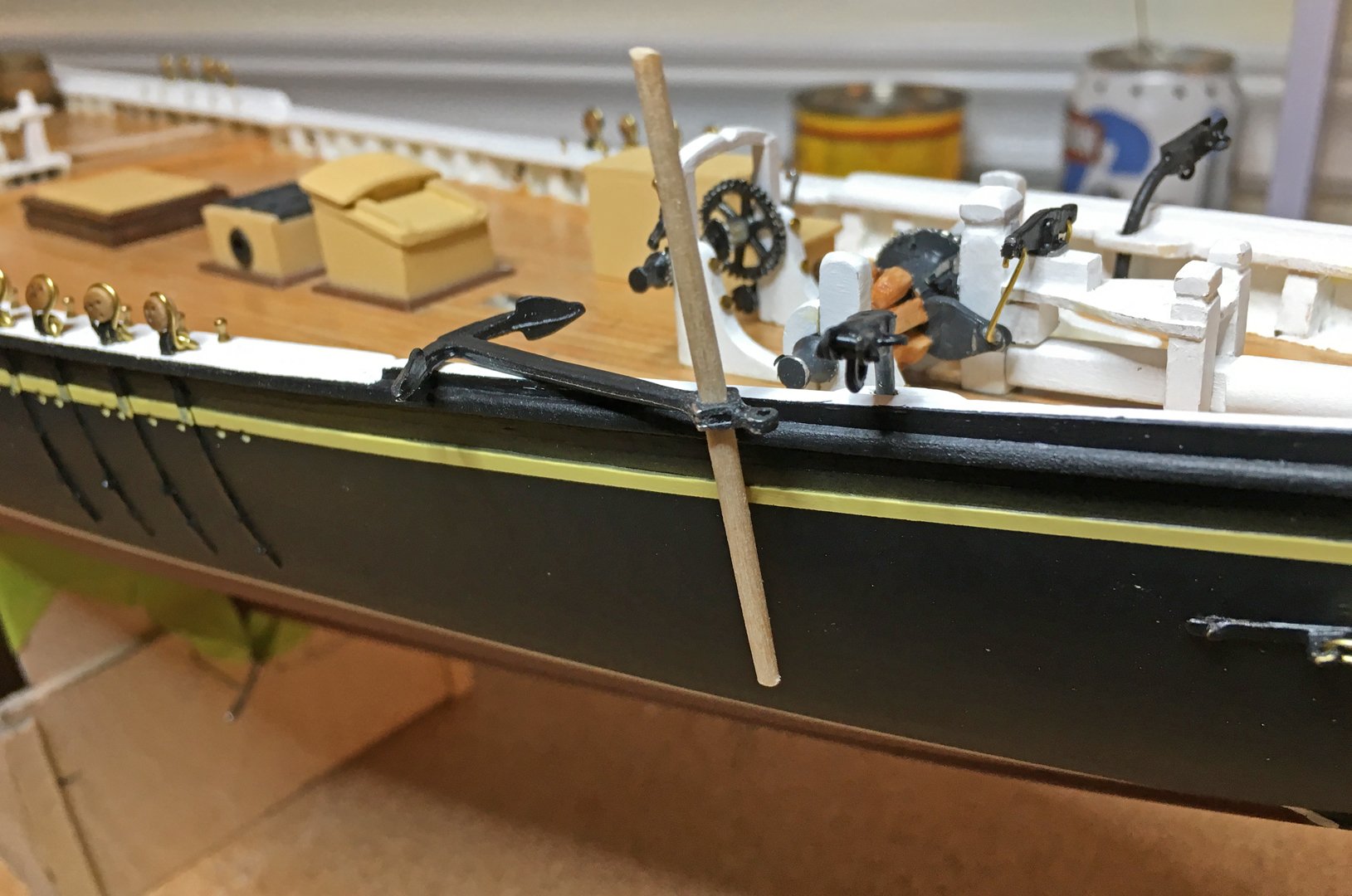
Well, your doubts show you were thinking! I have that book in my research library, but it's been years since I've opened it. The anchor pictured didn't register on my mind when I read the book. That anchor would be a tricky bit of ship smithing to craft. Note, however, that the anchor in the book, above, is nearly ten feet long from top to bottom! That's a seriously large anchor as might be found on an early Grand Banks fishing schooner three times as long as Glad Tidings. The working anchors on the 39' Glad Tidings probably wouldn't be any longer top to bottom than about four feet and wouldn't warrant the sort of forging sophistication that a ten foot tall anchor would, particularly not in 1937 when Glad Tidings was built and folding stock anchors of the proper size could be bought "off the shelf" in any chandlery in the country. So, I did a bit of internet sleuthing and ... Model Shipways "busted !" The Model Shipways model of the fishing schooner Benjamin W. Latham (http://site.nature-crafts.com/MS2109-Benjamin_Latham-Instructions.pdf) at the scale of 1/4" to the foot apparently uses the same anchor casting part (illustrated at figure 31 in the instructions) for the anchor on their Glad Tidings model at the scale of 1/2" to the foot. The Latham was 84 feet long, about half the size of Glad Tidings, so the 84' Latham's 10 foot tall anchor at 1/4" to the foot would be about 5 foot tall at 1/2" to the foot scale, close enough to pass off as the right size for their '39 Glad Tidings model scaled at 1/2" to the foot! The instructions for Model Shipways' model of the 143' Grand Banks schooner Bluenose at 3/16" to the foot (https://modelexpo-online.com/assets/images/MS2130_Bluenose NEW 7-15-20.pdf) comments at note 14, "Model Shipways' Grand Bank's anchors have Britannia shanks, but make their stocks from stripwood." The Model Shipways Glad Tidings parts list lists two "Anchor Shanks" as parts WP8150. Sure enough! Here's the Model Shipways Glad Tidings anchor as part number WP5801, "Anchor Shanks," on their Bluenose model (https://suburbanshipmodeler.com/2017/04/09/anchors/) : See: http://modelshipbuilder.com/e107_files/public/1554385959_5618_FT33665_img_0454a.jpg And here it is again as part number WP7124 on Model Shipways' Grand Banks schooner Benjamin W. Latham model: The casting of a folding stock anchor, particularly one with a stock that actually worked, would be a daunting, and, to the manufacturer's thinking, unnecessarily expensive detail. Kit manufacturers frequently use the same small parts in different kits, a practice that often results in gross errors of scale, although I've never seen an error in the type of a part, as here. It looks like all Model Shipways did was use an anchor which was style and period correct for their Grand Banks fishing schooners at twice the prototype size of Glad Tidings which was twice the scale of the Grand Banks schooner models. The size of the anchors Model Shipways provides for Glad Tidings is correct, or close to it, but the type and period of the anchors aren't correct at all.

- 138 replies
-
- 2
-
-
- glad tidings
- model shipways
- (and 1 more)
-
Very true, Eberhard. Unlike in Europe, over here, early marine engines were gasoline powered, large-cylindered, slow-turning behemoths. I've had the pleasure of being acquainted by a couple of them, which started by opening a compression-release lever, filling a small cup on a pet cock in the cylinder head with gasoline (or something "hotter" like starting fluid) and kicking a huge flywheel with your foot until you got it turning pretty well. Then one opened the pet cock to let the thimble-full of fuel run into the single cylinder, and quickly closed the pet cock and the compression-release lever. Hopefully, the engine would start with a "ka-thunk, ka-thunk, ka-thunk, ka-thunk,... turning a large, high-torque propeller, and off she'd go. There are still some of these old engines in a few preserved privately owned historic vessels and in museums. The most well-known of the type, the Hicks Engines, were manufactured in my home town, San Francisco. The technology of these high-torque early gasoline marine engines reflects their steam powered antecedents. And since this is a modeling forum, here's a 1:8 scale working model of a similar Hicks engine. I don't know this modeler, but I'd sure like to meet him. Talk about an amazing example of model engineering. Truly mind-boggling!
-
I realize that the anchors are those provided by the kit manufacturer, but, although I am quite familiar with many boats of this relatively modern boat's era, I've never seen a wooden stocked anchor with the stock passing through a square hole or band through the shank as these Model Shipways anchors do. (Not to mention that wooden stocks on anchors of any size were long obsolete by the time Glad Tidings was built.) That isn't to say there never was such a thing, but this is the first I've ever seen of one in more years than I'd like to admit at this point in my life. It would seem that the manufacturing of such an anchor would be a lot of trouble for not much, if any, benefit and add unnecessary weight. Generally, a late 1930's boat of this size would, contemporary with her launching, carry a standard folding "fisherman" anchor with a metal stock that slid through the shank such that the stock could be positioned to lay alongside the shank when the anchor was stowed flat on the deck, rather than slung on the rail. This was a big improvement over fixed stock anchors and became near universally employed when they became available. In my experience, wooden stocks, when employed, were fitted in pieces over the shank of the anchor and never through the shank. I want to stress that this is no criticism of the model, which is beautifully done. Just a question about a note of historical accuracy. If anybody knows of this unusual stock design, I'd be interested in hearing more about it. Howard I. Chapelle designed Glad Tidings as his own personal yacht and he knew what he was doing. Perhaps he wanted anchors that looked "old fashioned," but that's just a guess, and, if so, why didn't just make them to fit around the shank as usual? Standard galvanized folding stock "fisherman" anchor as assembled for use: Folding stock "fisherman" anchor folded: http://www.herreshoffregistry.org/forum/images/Anchor_1.JPG Folding stock "fisherman" anchor stowed as read for deployment: Folding stock "fisherman's" anchor as stowed long-term on deck pads made of wood, or, as here, of cast metal: (Note, the picture merely shows how the pads were commonly placed, but the anchor and pads are here obviously just laying on a hardwood floor, not a boat deck, for photographing. Pad eyes, were usually set into the deck. Lashings would be rove through the pad eyes and around the shank and/or fluke arms to secure the anchor to the deck.) Or stowed below, here in a lazarette locker: Herreshoff patent three-piece anchor: Note unique features: Stock runs through the shank and the shackle eyes with cotter pins holding stock in place outside of shackle eyes on each side and the flukes at the crown in this example. (Other examples used a key rather than a pin.) Herreshoff three-piece patent anchor parts disassembled: Note flared lower end of the shank against which the flukes fetch up. One distinctive advantage of the Herreshoff patent anchors was that because they could be broken down into their component parts, the design was particularly well suited for use as heavy, and (hopefully) infrequently used storm anchors which could be stored, disassembled, in the bilges, keeping the weight low in the vessel and being more easily capable of getting from the bilge to the deck in parts before assembly. In this fashion, a 150 pound storm anchor could pretty easily be brought on deck in fifty pound increments that were easily moved about below, unlike a 150 pound anchor with fixed flukes, shank, and stock. Chapelle was an accomplished yachtsman and at the time he designed and had Glad Tidings built, it would have been quite possible he equipped her with Herreshoff patent anchors as they were, for their time, the most efficient and reliable anchors available, pound for pound, due to their scientific engineering. Here's an extensive article on the Herreshoff patent anchors, if anyone wishes more information on them: https://www.woodenboat.com/herreshoff-three-piece-stock-anchor Obviously, the fixed stock anchors supplied with the kit leave no other practical option for stowage but slung over the rails port and starboard, as shown in the plans. Were folding stock anchors actually carried on the prototype, they would never have been stowed over the rails in fixed-stock fashion when under sail, except on short trips between anchorages as such a stowage arrangement invites chafe and topside gouges and presents the risk of sheet fouling when tacking, which is less of a consideration in vessels sheeting the jib on a traveler, as does this one. Anchor rodes should, at a minimum, be eight times the depth of the deepest water in which the vessel is expected to anchor. If, for example, the greatest anchorage depth expected is thirty feet, 240 feet of anchor rode would be required. While it's difficult to know for sure from the photos, it appears the rodes attached to the anchors are nowhere close to 240 scale feet. One might carry the total rode required in separate lengths, for ease of stowage. However, in any event, the rodes would never be carried on deck "flemished" (coiled flat) as depicted when under sail. The rodes would not run free from the outside of the coil, as depicted and one flush of green water over the foredeck would instantly turn those flemished mats into a tangled mess strewn up and down the waterways. (Normally, they would be run through a chain pipe on deck to a rode locker below, or stowed below separate from the anchor when not in use.) Flemishing was an affectation employed on naval ships when dressed for inspection, frequently seen on the falls of the gun tackles, but never done during operations. A fouled gun tackle fall, e.g. a hockle jammed in a block, can put a gun out of commission for as long as it takes to remedy, thereby reducing it's rate of fire. So, I offer these thoughts not as any gratuitous criticism of what is a masterfully built model and a beautifully presented build log, but out of genuine intellectual curiosity and in the possible event that the kit plans, even from a manufacturer as highly regarded as Model Shipways, may contain an historical error. I readily acknowledge that it's entirely possible that I may be "whistling into the wind." I gave it some thought and figured that I might have something to share on the subject and because I believe it is more collegially helpful to question apparent errors gracefully to say nothing. This may be a topic for a separate thread sometime, but I'll mention in closing that my own "rule of thumb" is that if I think that an apparent minor issue with a model is one which could mean the difference between a win and an "also ran" in a competition, I'll say something because if I were in the modeler's shoes, I'd appreciate someone bringing it to my attention. Little is to be learned by the large number of congratulatory posts so often seen in other modeling forums. They generate a lot of warmth, but little light.
- 138 replies
-
- 2
-
-
- glad tidings
- model shipways
- (and 1 more)
-
My God! What a story. What was he thinking, then? You must have wanted to kill him.
- 138 replies
-
- 2
-
-
- glad tidings
- model shipways
- (and 1 more)
-
Strips of copper, zinc, or lead roofers' flashing material are often good for taking off curves, as well.