


Glenn-UK
-
Posts
2,638 -
Joined
-
Last visited
Content Type
Profiles
Forums
Gallery
Events
Posts posted by Glenn-UK
-
-
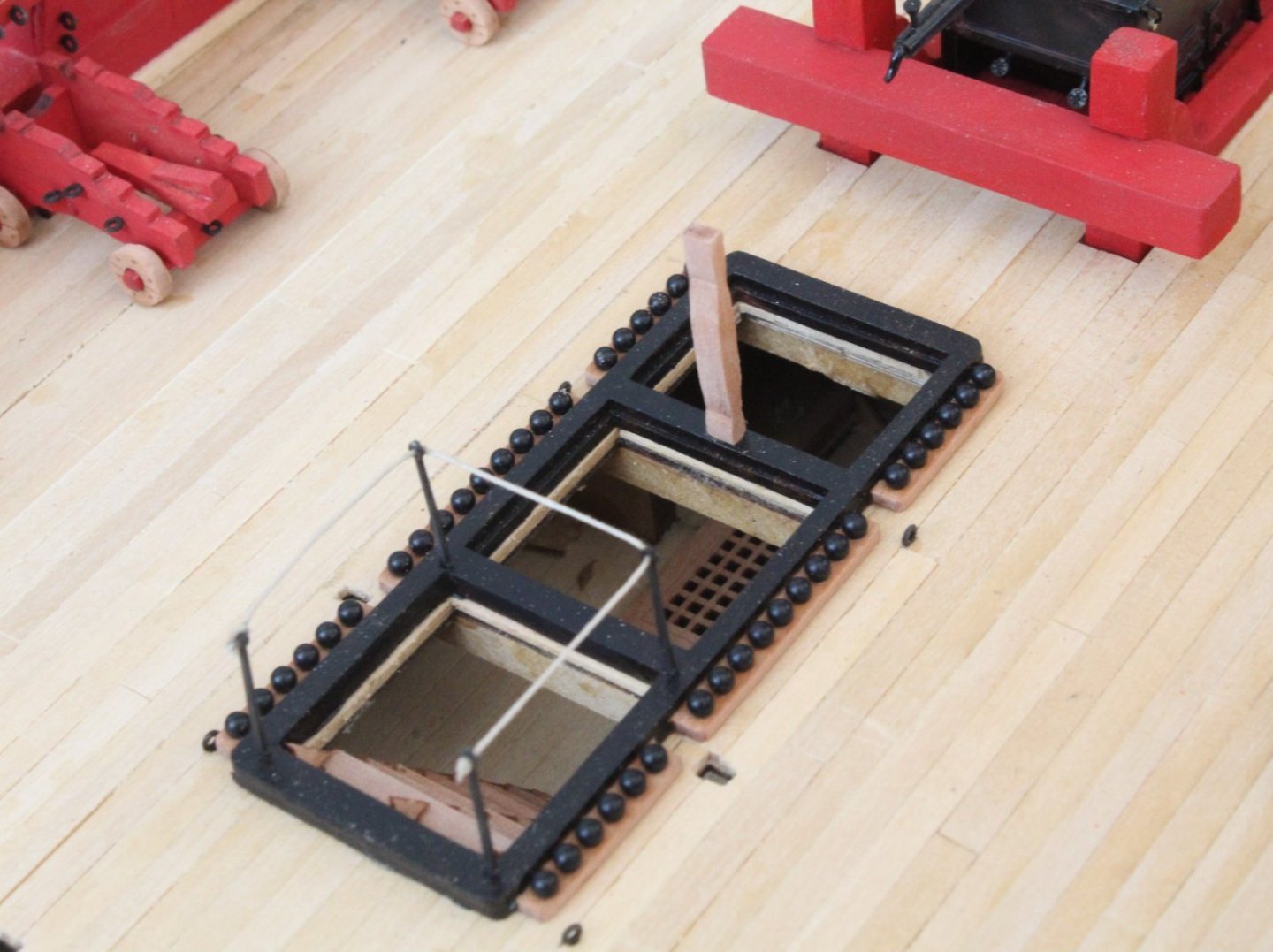
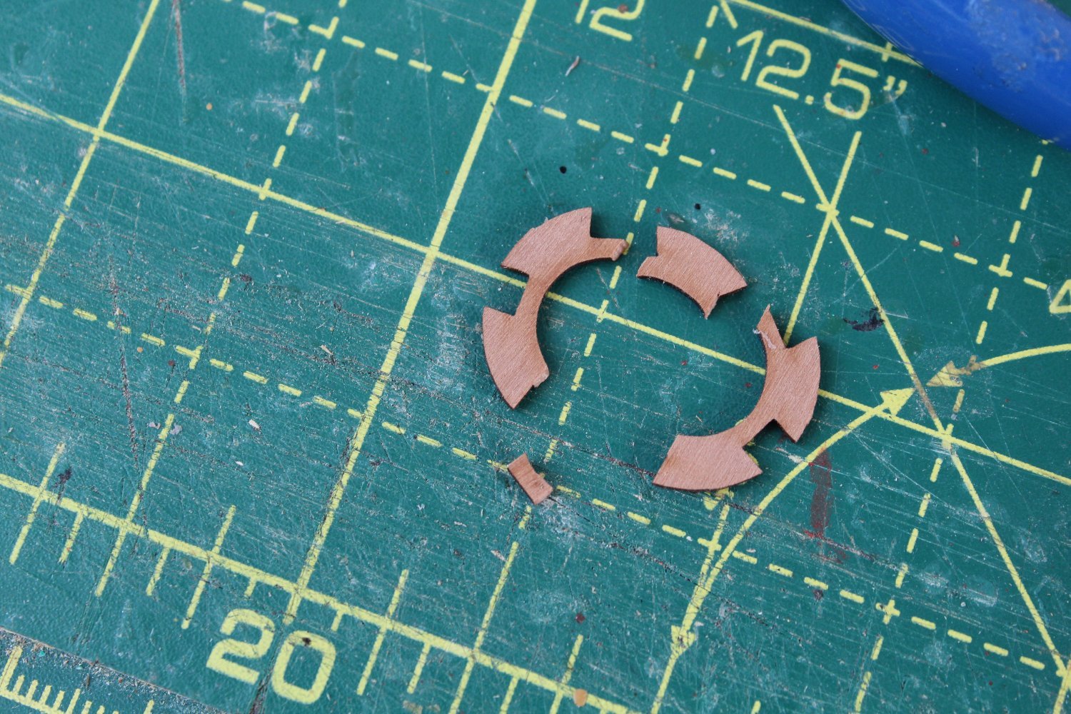
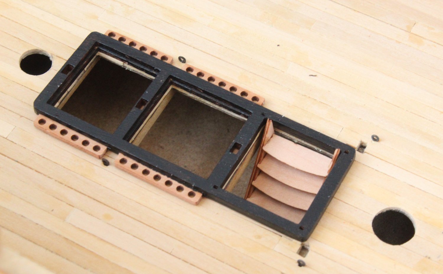
Gun Deck Hatches
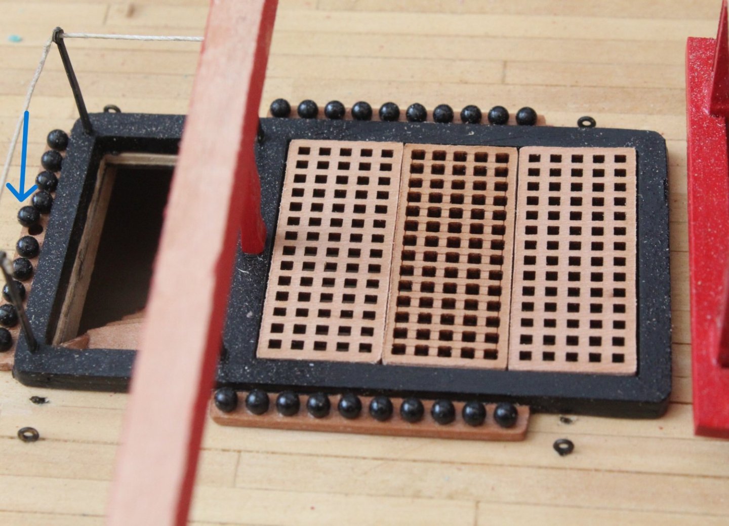
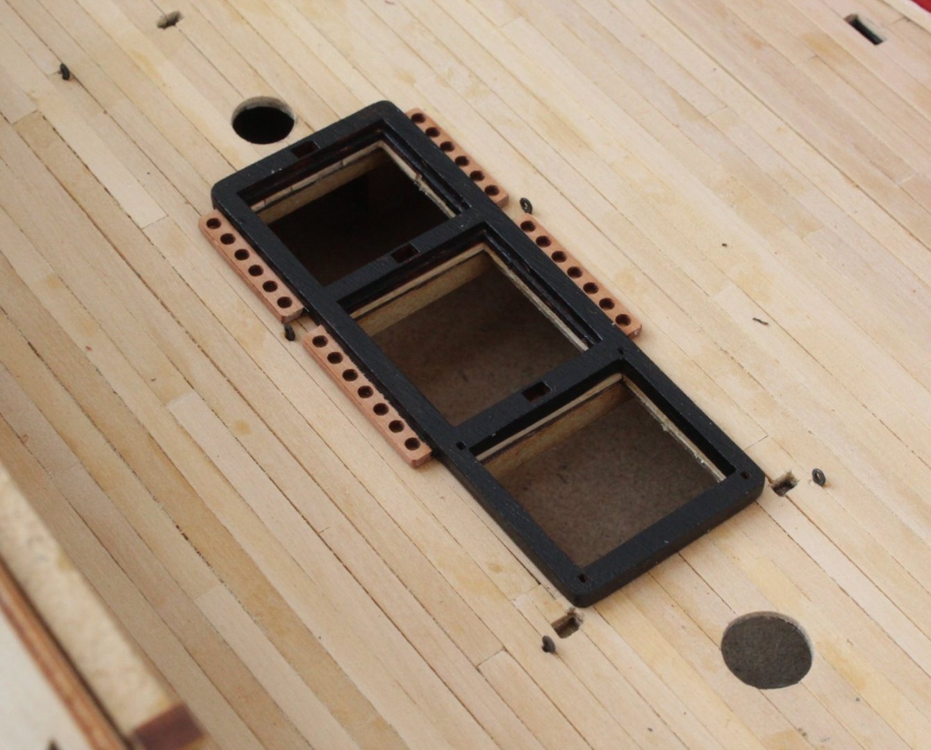
I realised that I had not fitted the coamings to the gun deck hatches. This has now been rectified.
When looking at the next photo I noticed one of cannon balls is trying to escape.
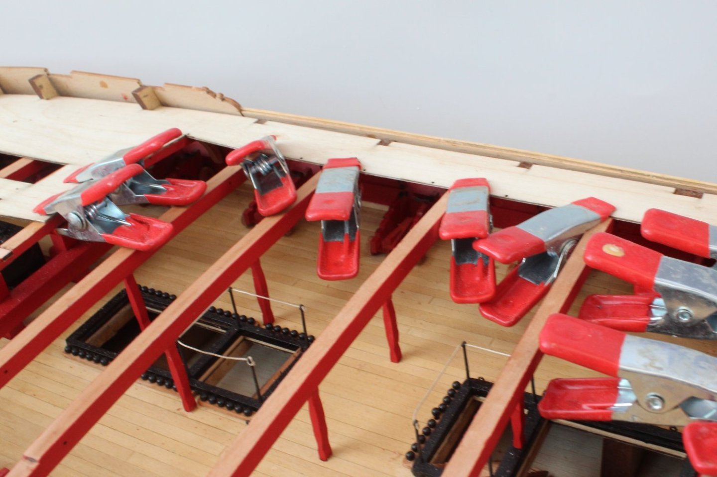
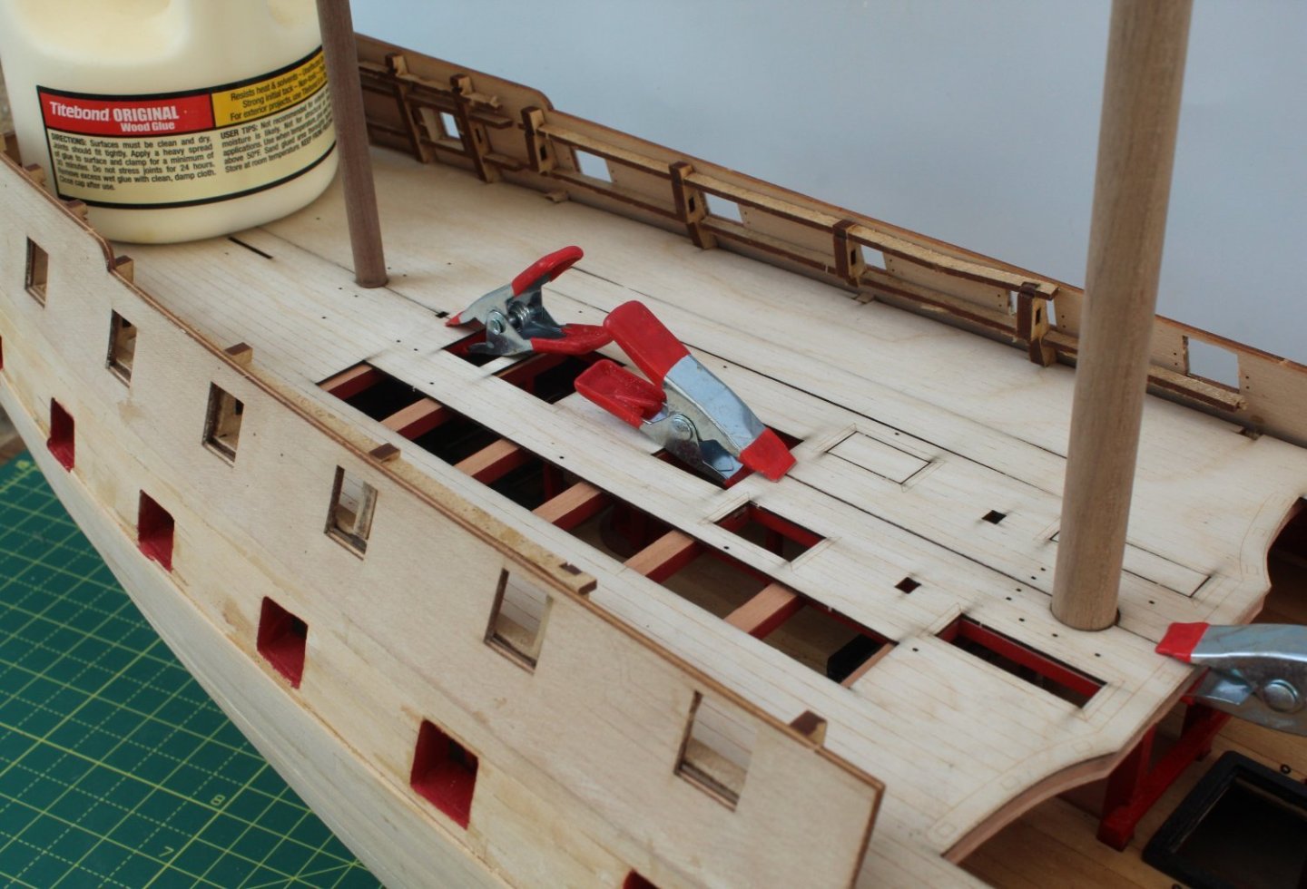
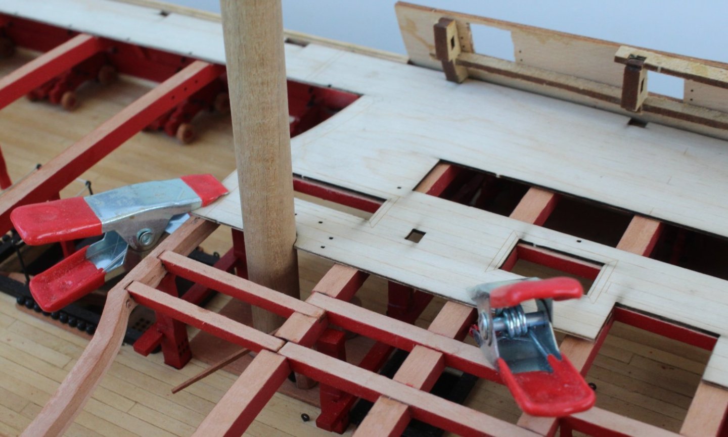
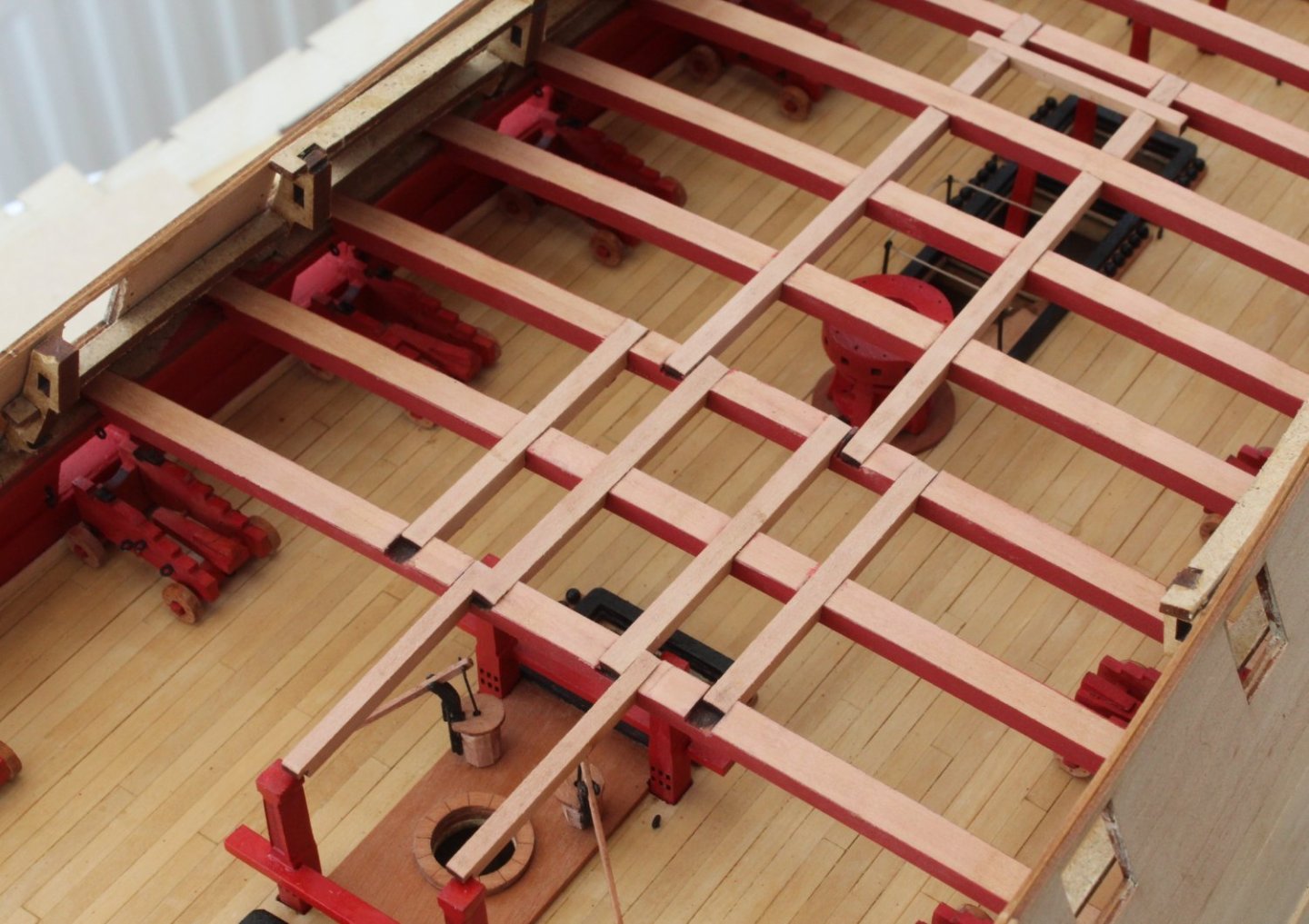
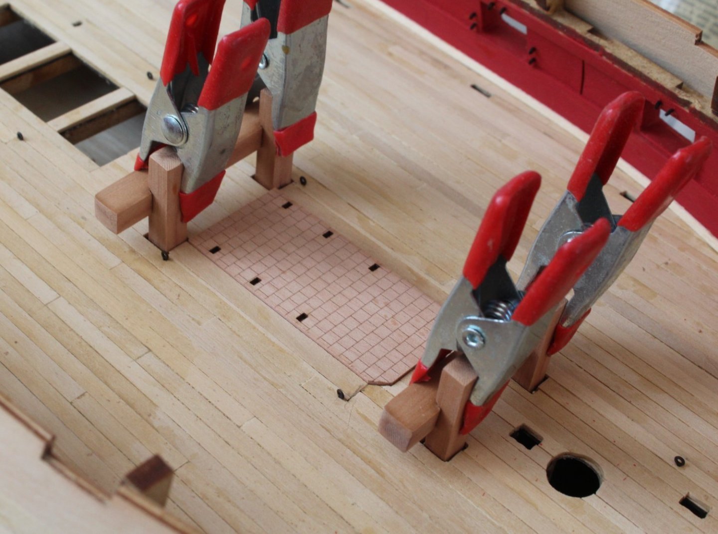
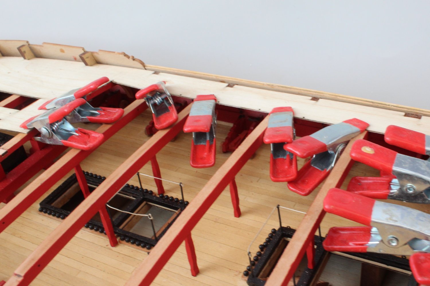
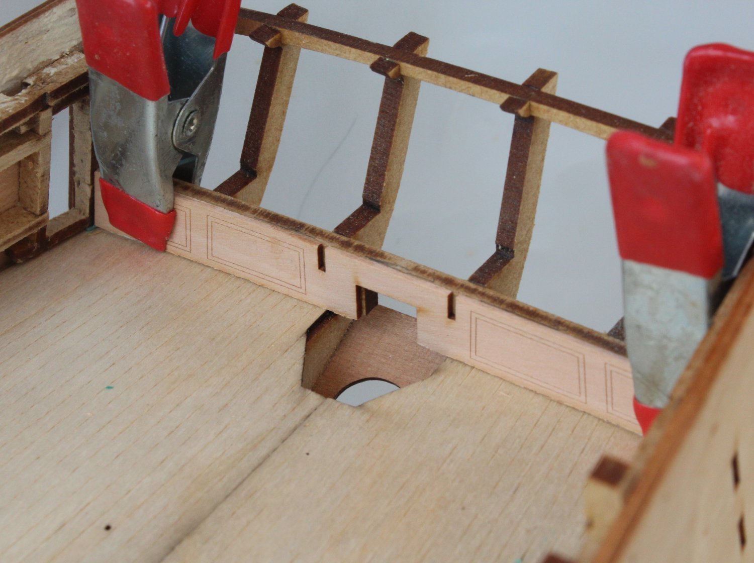
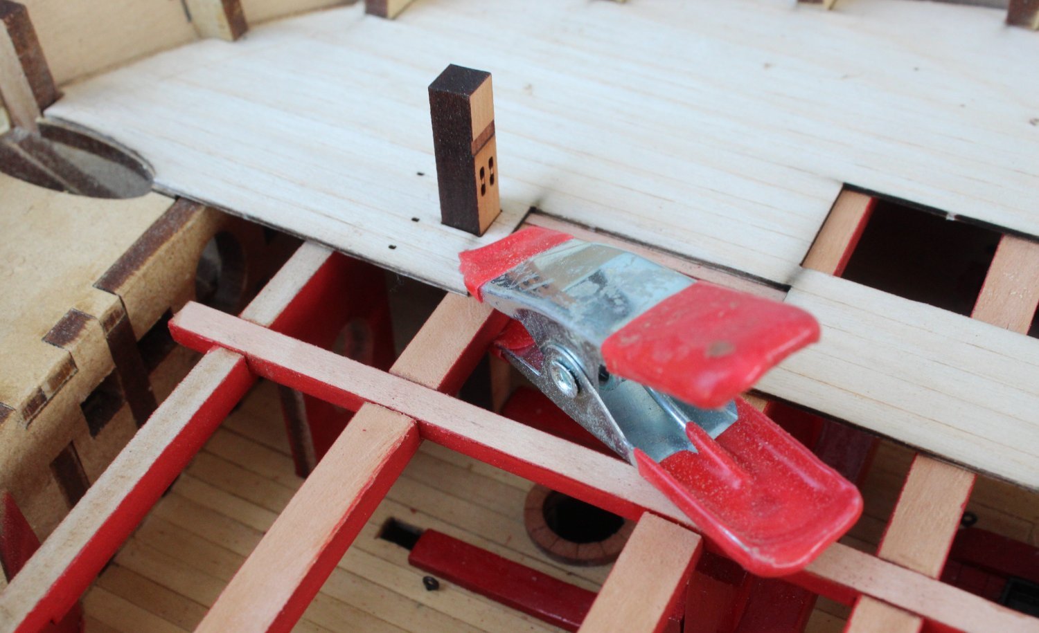
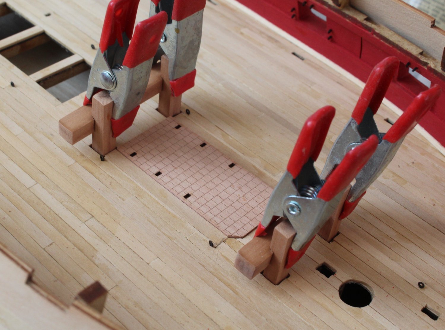
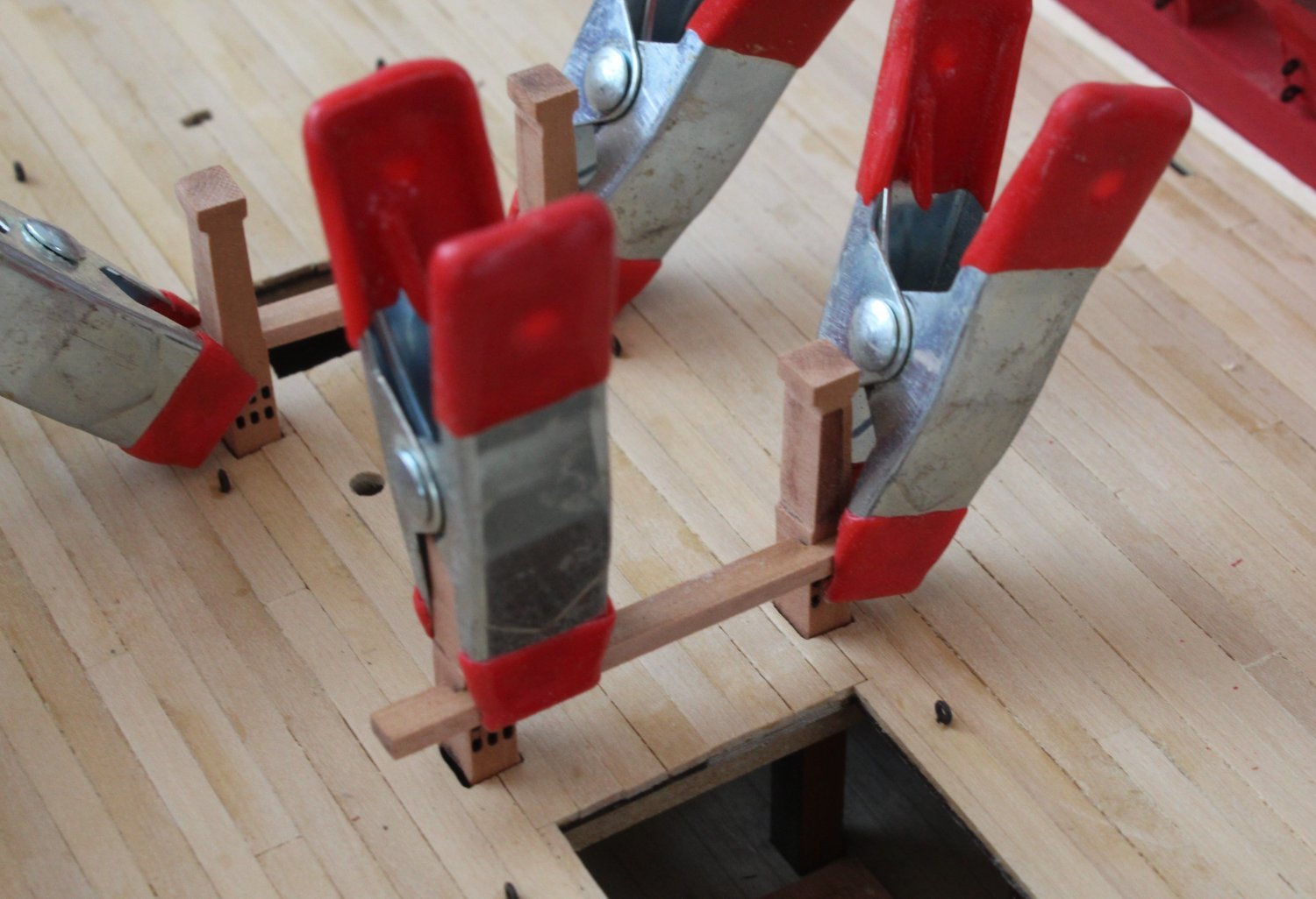
I did consider the suggestion made by Jim of splitting the deck patterns in to three parts, but decided to try gluing the first (right hand side) as one complete piece. Using plenty of the clamps the deck pattern was glued in place.
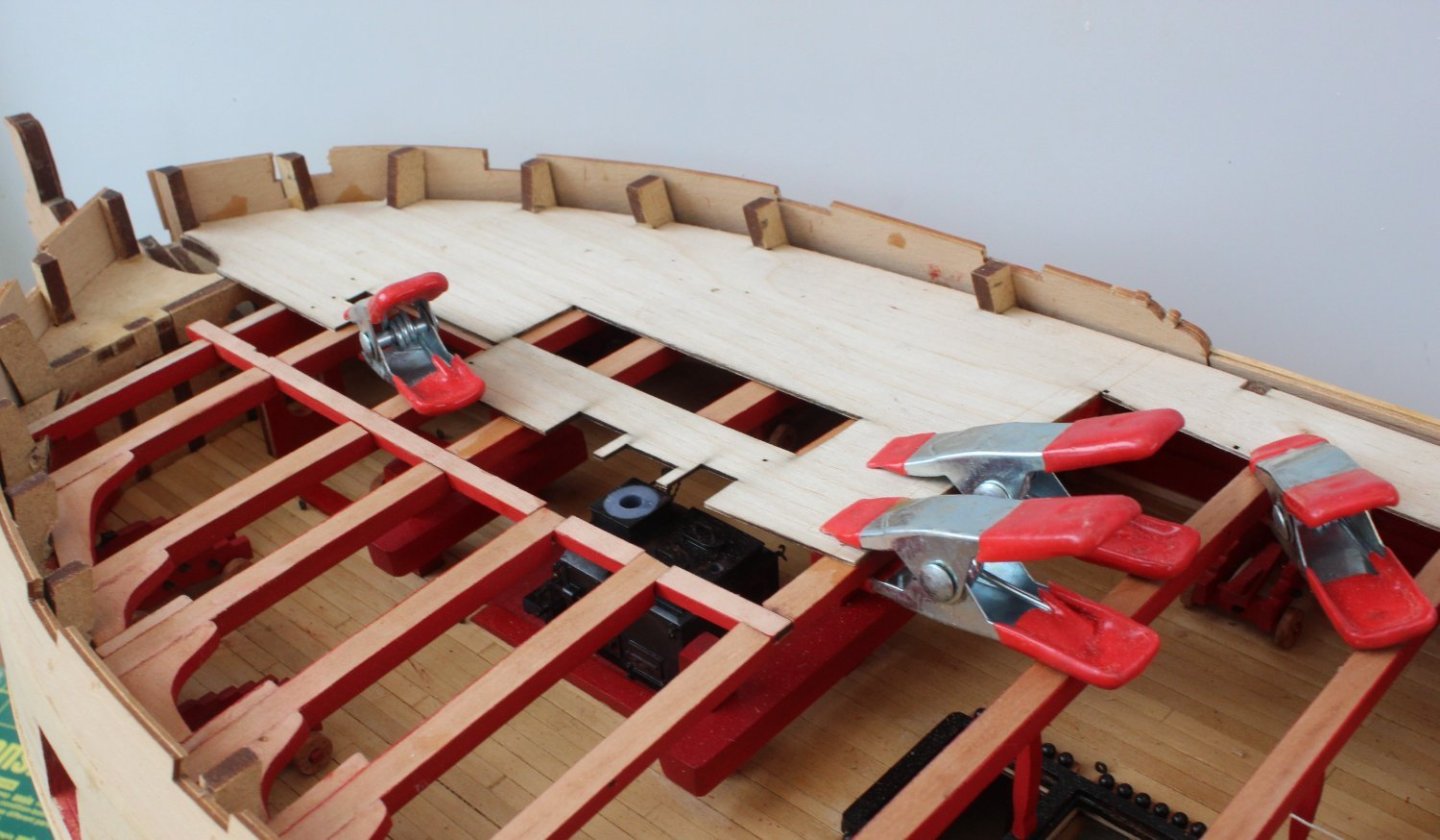
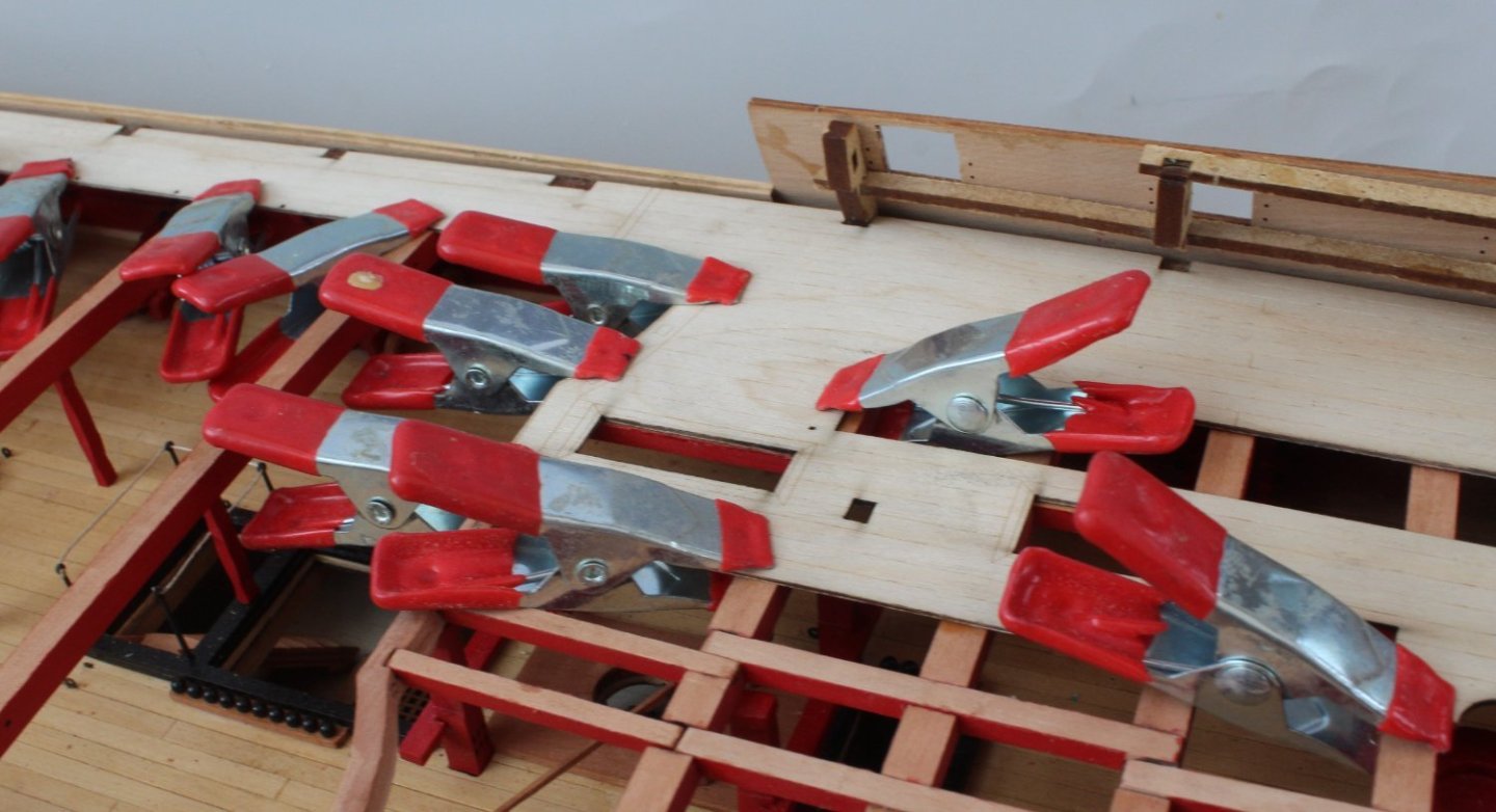
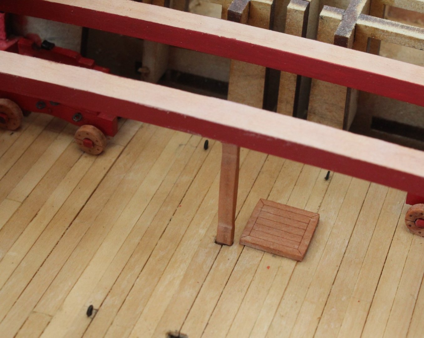
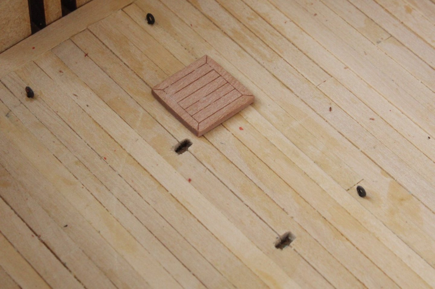
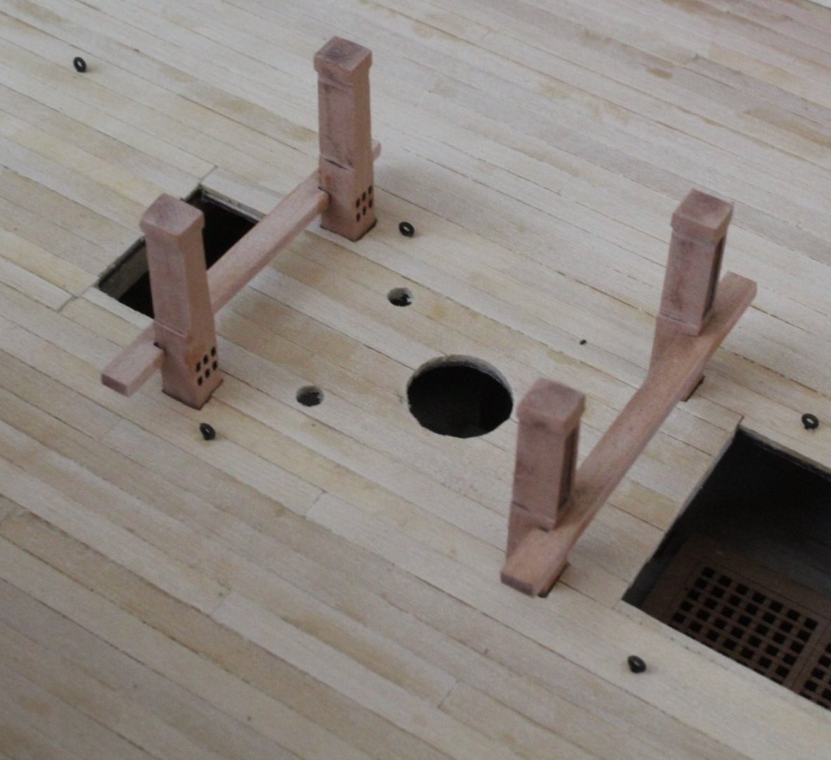
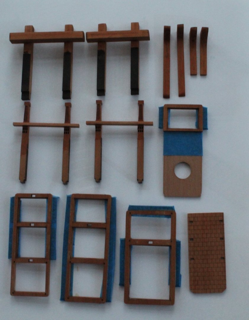
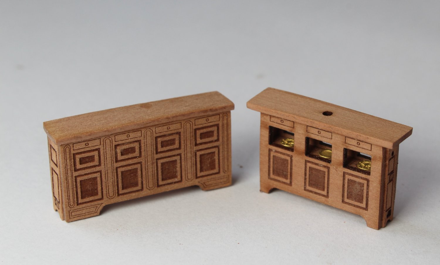
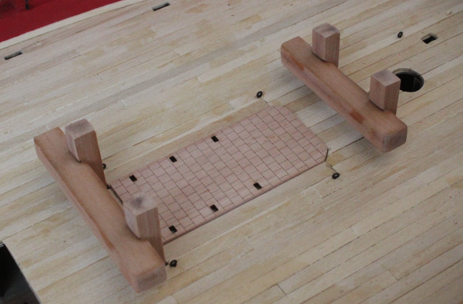
Whilst waiting for glue to dry I decided build a couple of deck items. I think they turned out OK.

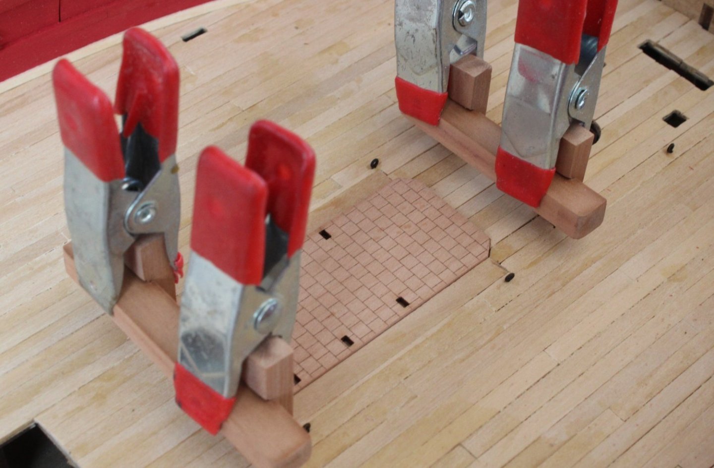
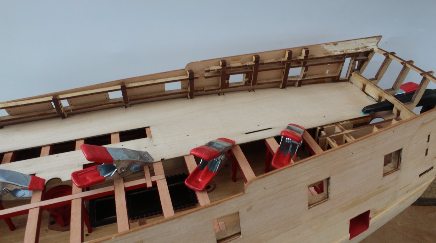
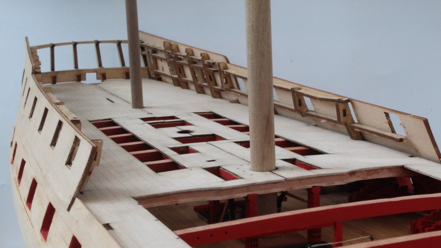
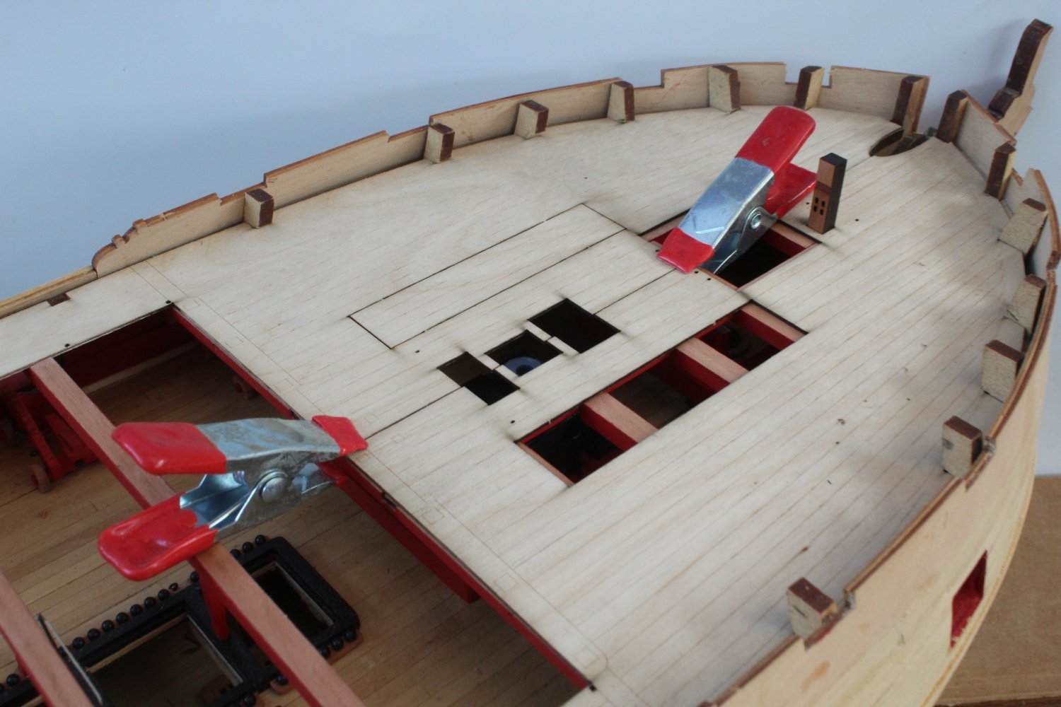
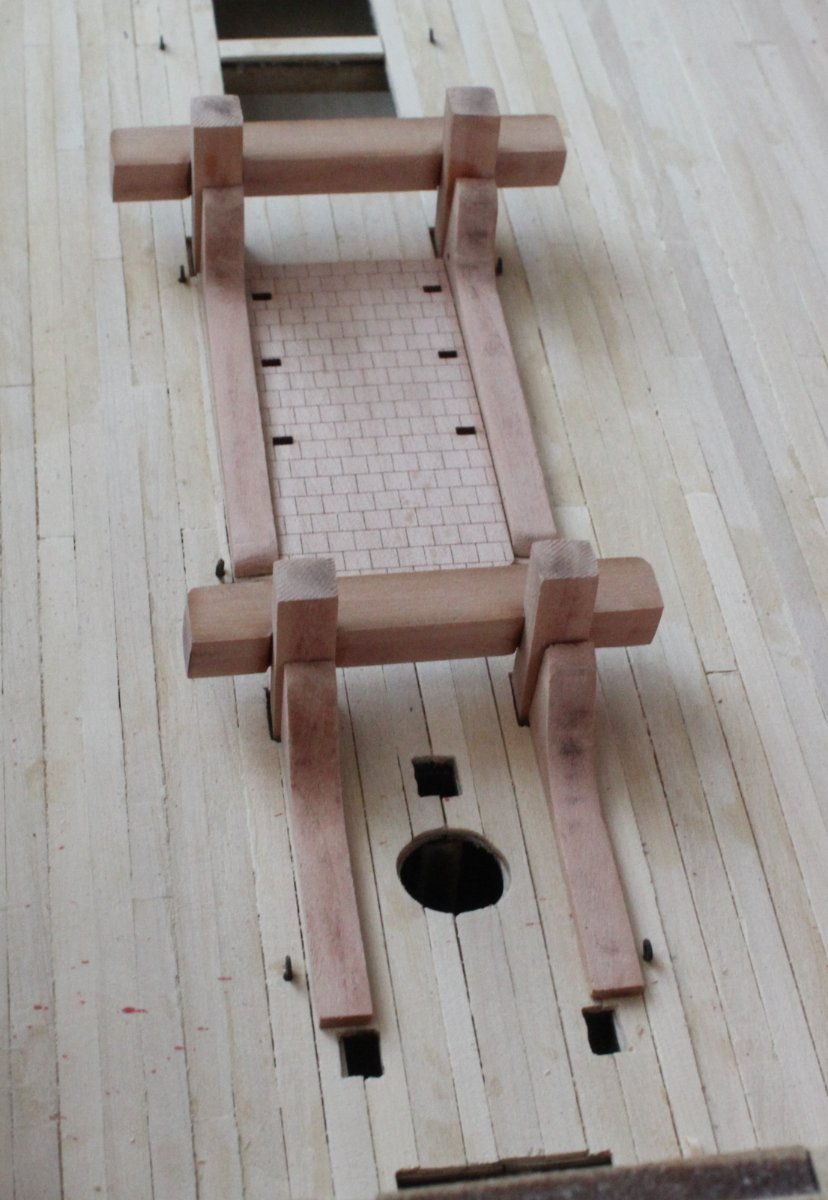
After another trial fit of the left hand deck pattern I decided to fit as one complete piece. There was plenty of clamps used as the glue was left to cure. A couple of hours later the clamps were removed and the masts and bitts were test fitted. Everything was perfectly aligned.


The scrap framework was then successfully removed and the remaining bulkhead ear remnants were sanded flat to the deck level.

The remaining bulwarks were then sanded smooth.

To finish of todays work a test fit of the stern cabin rear bulkhead was undertaken. I also started to look at the assembly of the rudder casing and concluded that this is going to be a tricky little item to build.

-
-
Upper Deck Trial Fitting - Left Hand Side
As with the right hand side I did have to trim a bit of back edge in order to line up the upper deck pattern with the bulkhead ears.
After cleaning the laser char from the edges a trial fit was undertaken.
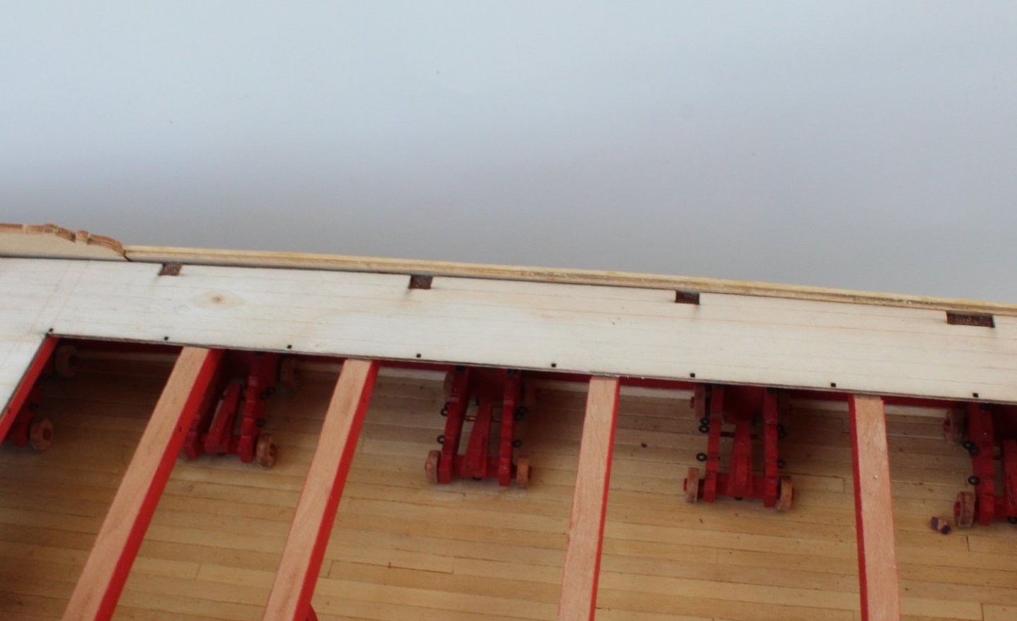
As can be seen in the first photo below the quarterdeck section is a perfect fit.
The gangway section also was a great fit, with the pattern sitting in the slots provided.

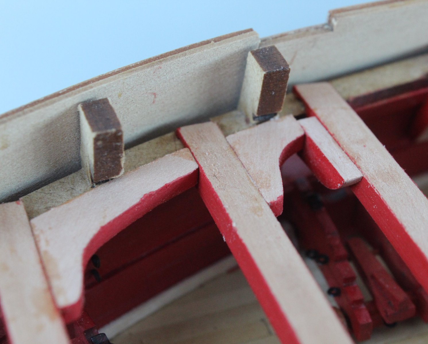
However the forecastle section requires a bit more work as the pattern will sit flush with the right hand pattern.
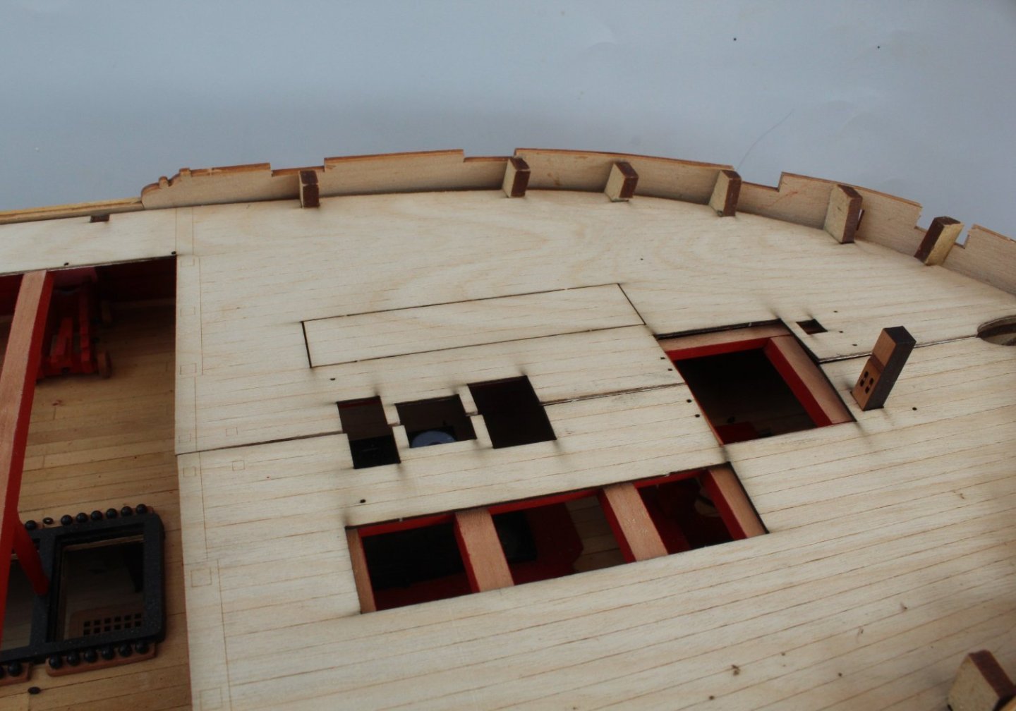
The alignment problem was due to pattern not locating fully in to one of the bulkhead ear slots. After a little bit of sanding of the slot opening the deck pattern was refitted and this time it became fully engaged. It will require a little bit more fettling to ensure the central sections of both patterns are aligned.

-
30 minutes ago, chris watton said:
The gap along the edges is intentional, as I saw no need to bring the edges of the deck right to the edges of the bulwarks, negating the need for possible sanding.
Thanks Chris, nice to know it not my back workmanship.
- mtaylor, Mr Whippy and chris watton
-
 3
3
-
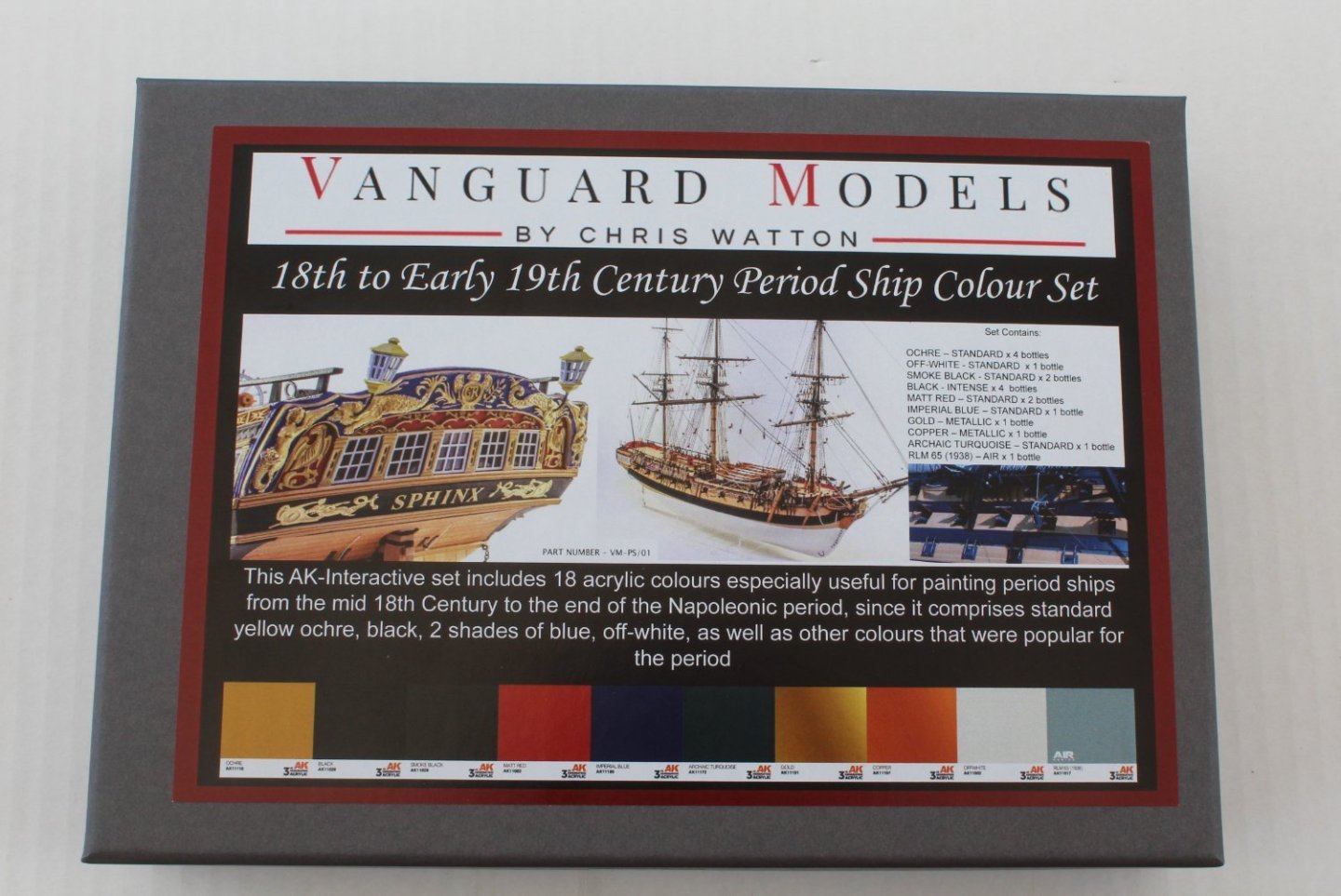
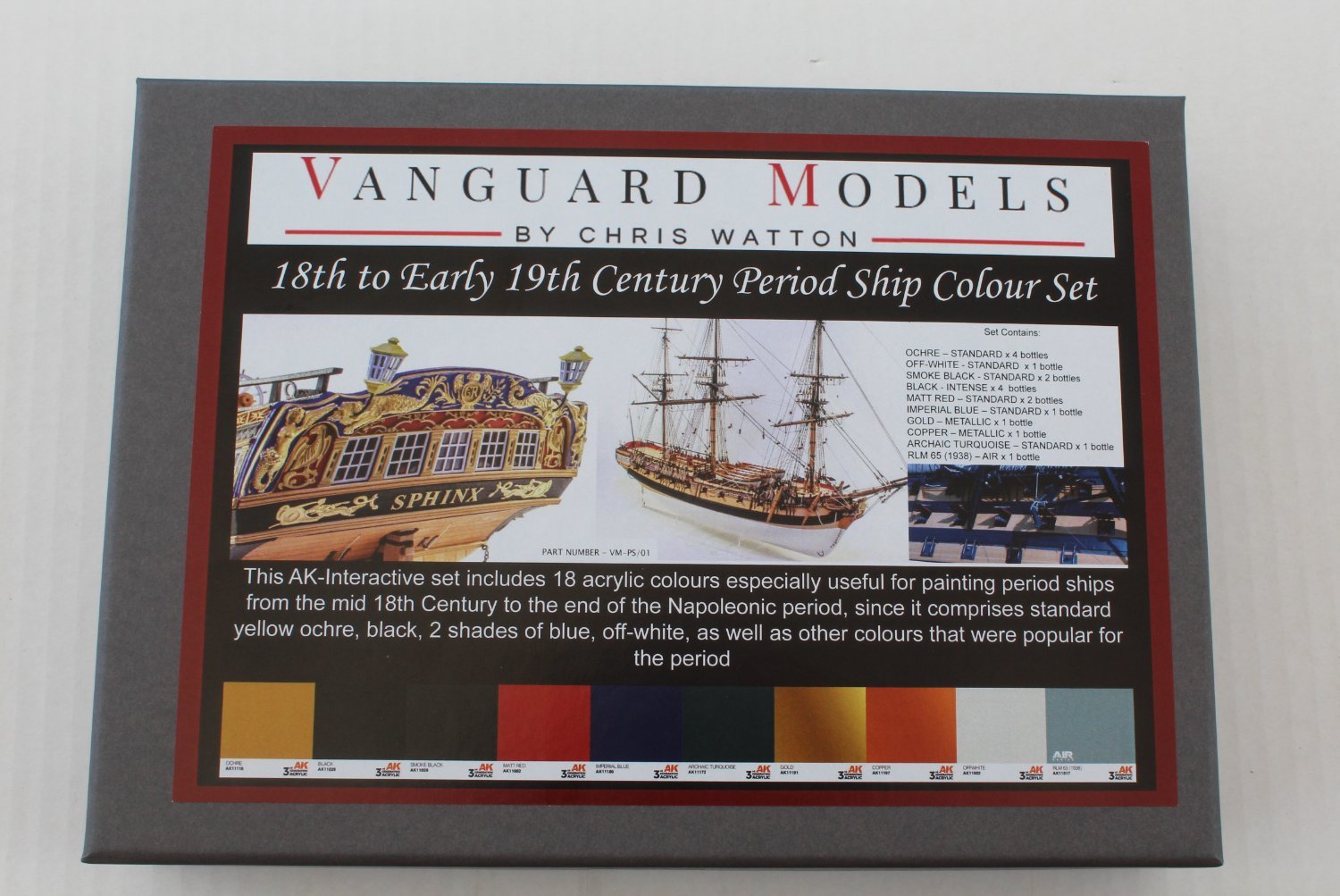
Paint Set
I treated myself to a set of paints in readiness for the next phase of the Indy build.
Quarterdeck Hanging and Lodging Knees
After painting the various quarterdeck knee parts I spent a couple of hours this morning fitting them to the Indy. I did have to shape all the hanging knees before fitting. As I indicating in my previous post it would have been much easier to check the fit of the hanging knees prior to gluing the deck beams in place and to then fit them as each deck beam was added. Considering these items will be very difficult to see I was not too worry about my shoddy workmanship.

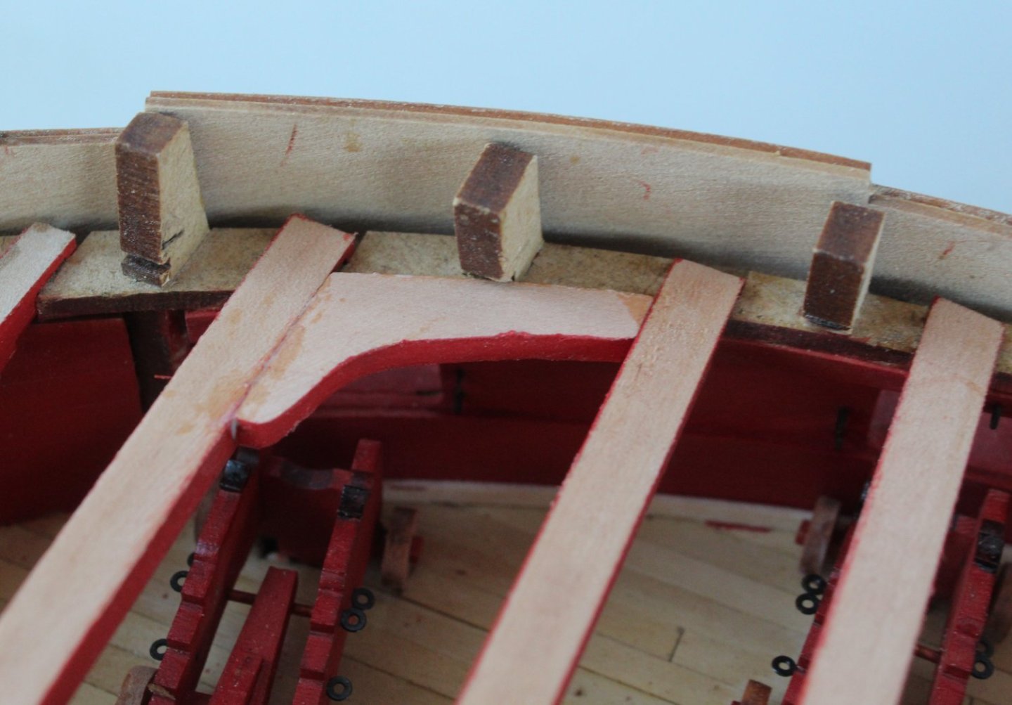
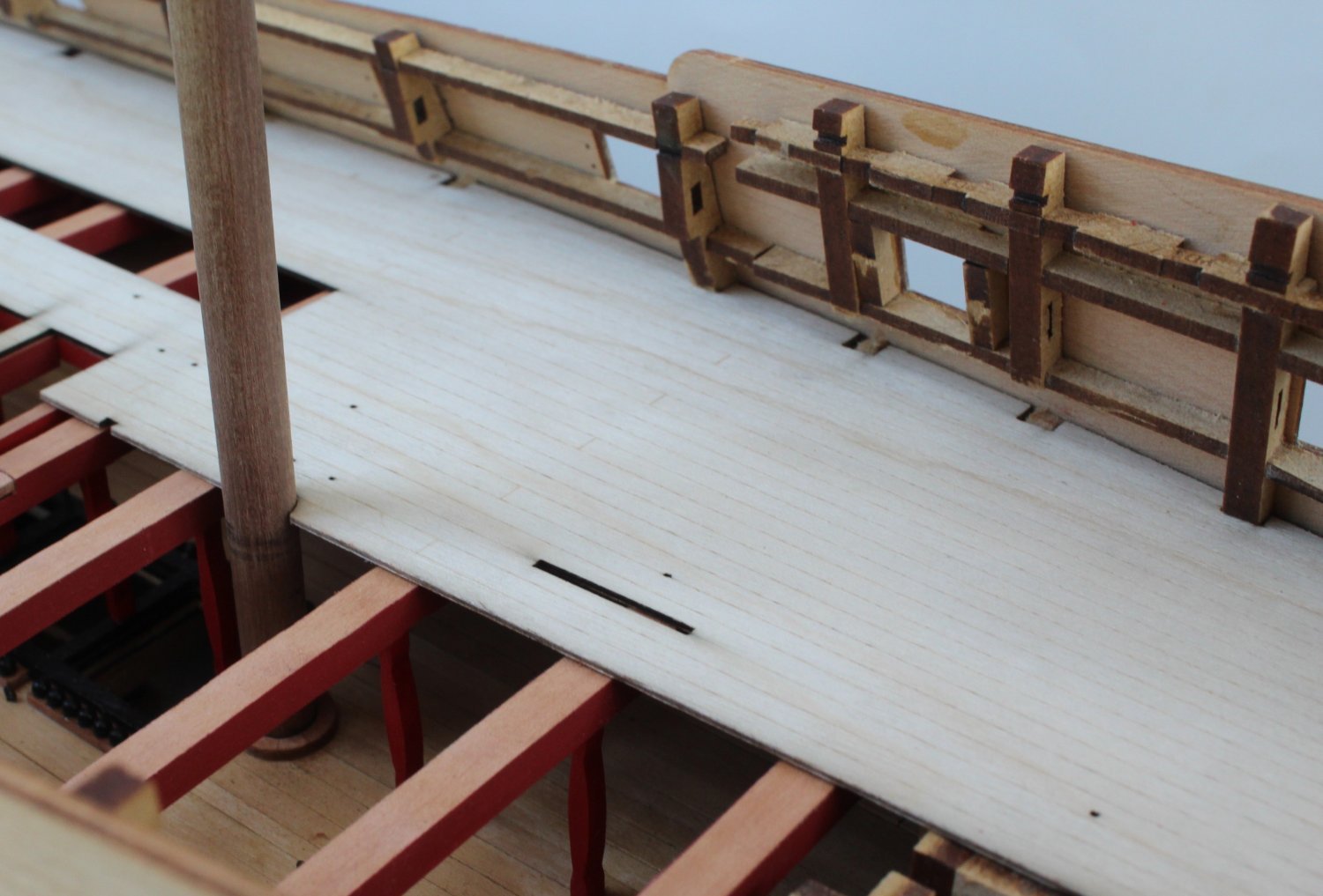
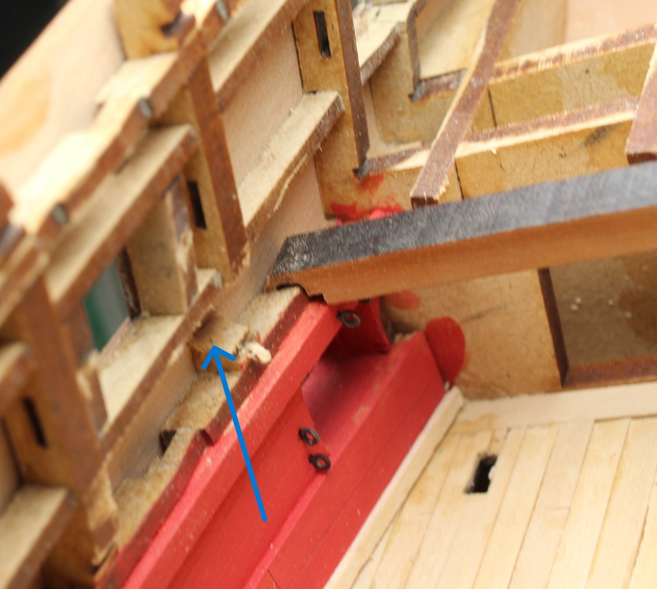
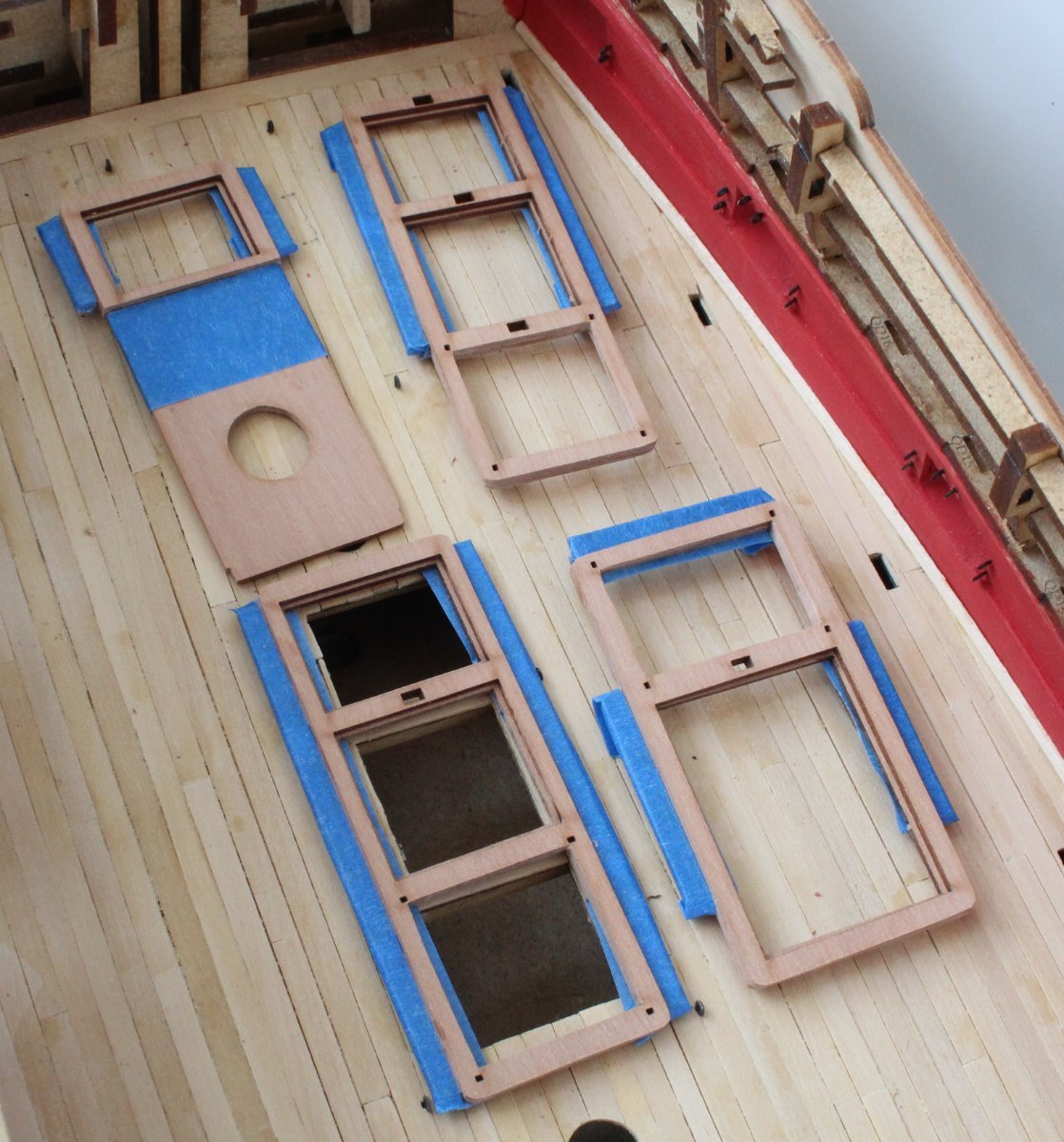
Upper Deck Pattern - Right Hand Side
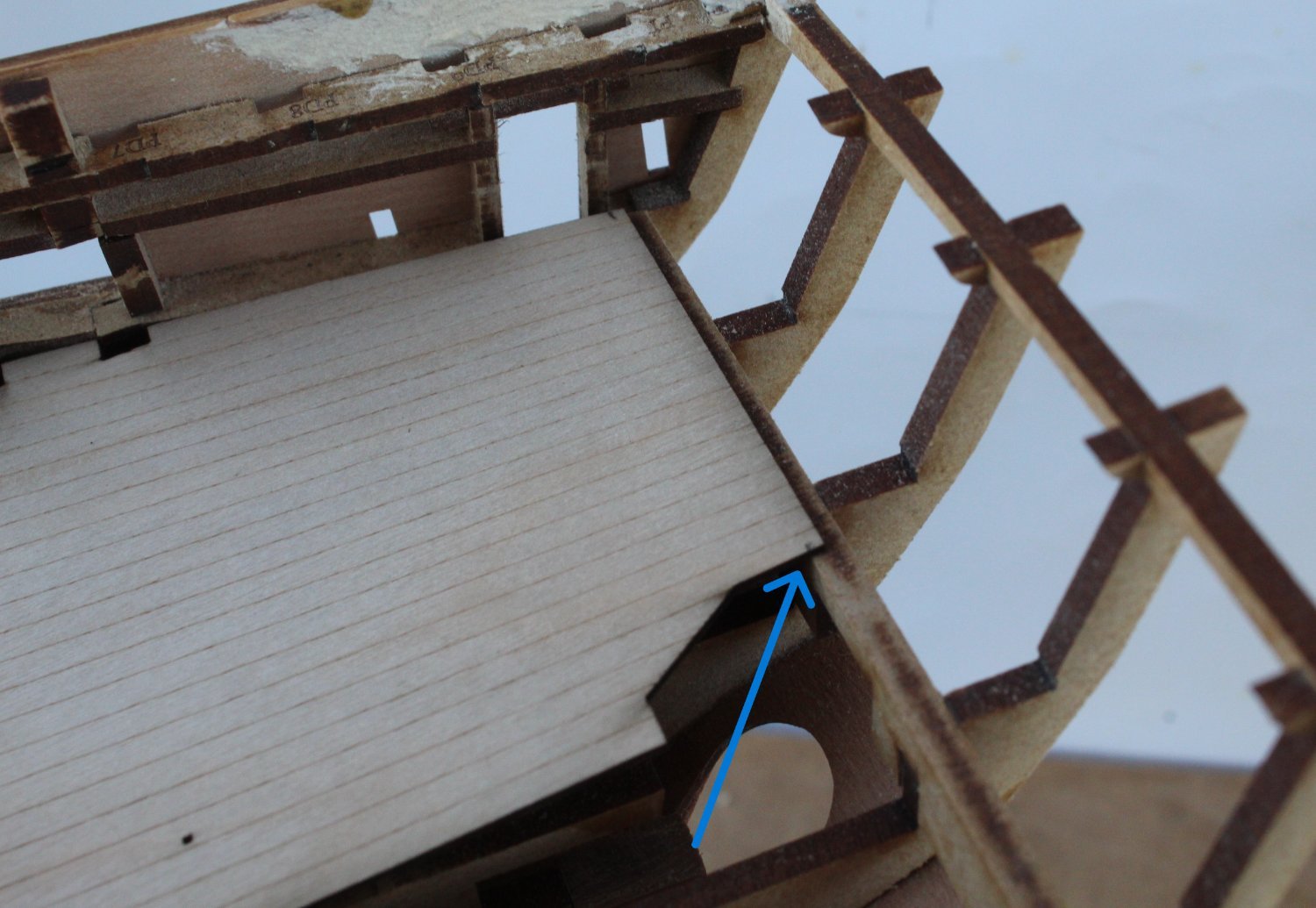
The upper deck base pattern comprises a right hand and left hand base pattern. Each base pattern includes the quarterdeck, gangway and forecastle decks. Starting with the right hand side pattern I removed the laser char from the edges, checked and cleaned the locating slots on the bulkhead ears. The pattern was then lined up with the bulkhead ears.
On first glance everything looks good but on closer inspection the deck does require a trim at the stern end, as indicated by the blue arrow.

Once the deck was trimmed the upper deck (right-hand side) was test fitted. It seems to be a good fit and the holes for both the mizzen and main masts are perfectly aligned with the gundeck holes below.

The gangway section sits nicely in the slots on the deck beams.
The forecastle bitt pattern is also perfectly aligned with the lower deck locating slot.

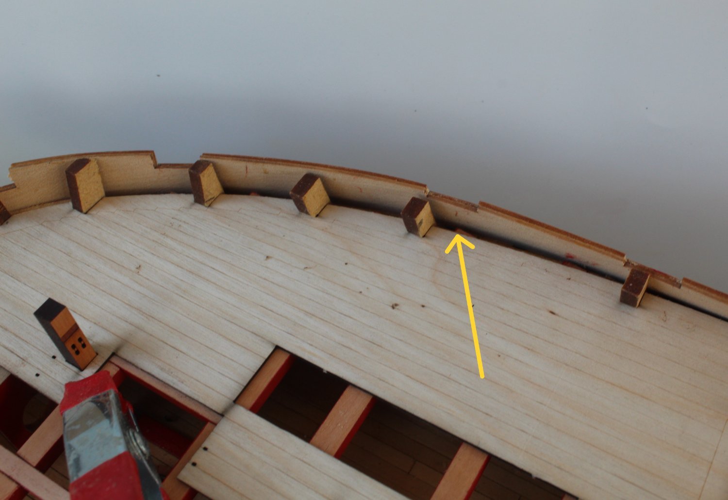
My fairing of the upper section of the forecastle bulkheads could have been better however, as can be seen by the yellow arrow. This gapping will be hidden once the ears have been removed and the inner bulwark patterns and forecastle deck planking have been added.

I now have to repeat the process with the left hand pattern. Once I am happy with how it fits I will glue both parts in place.
- mtaylor, chris watton, Mr Whippy and 4 others
-
7
-
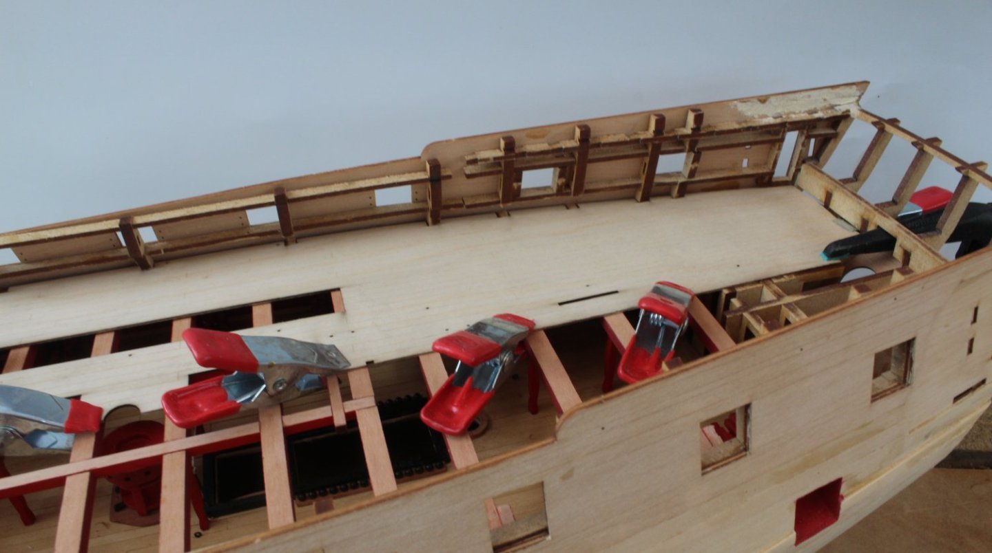
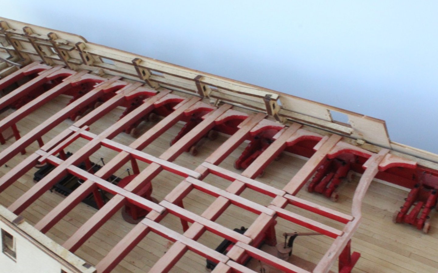
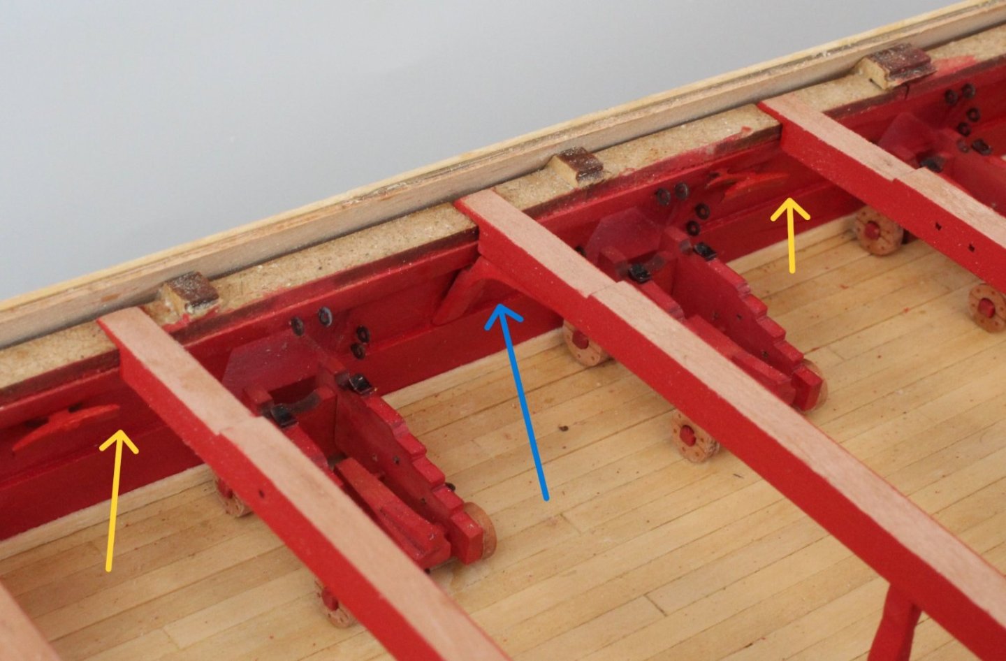
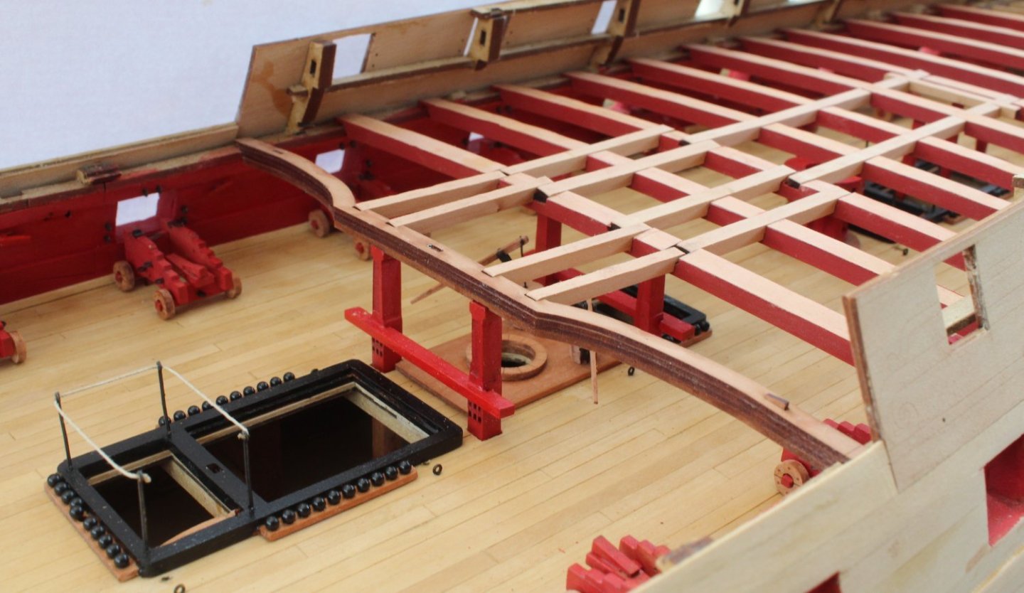
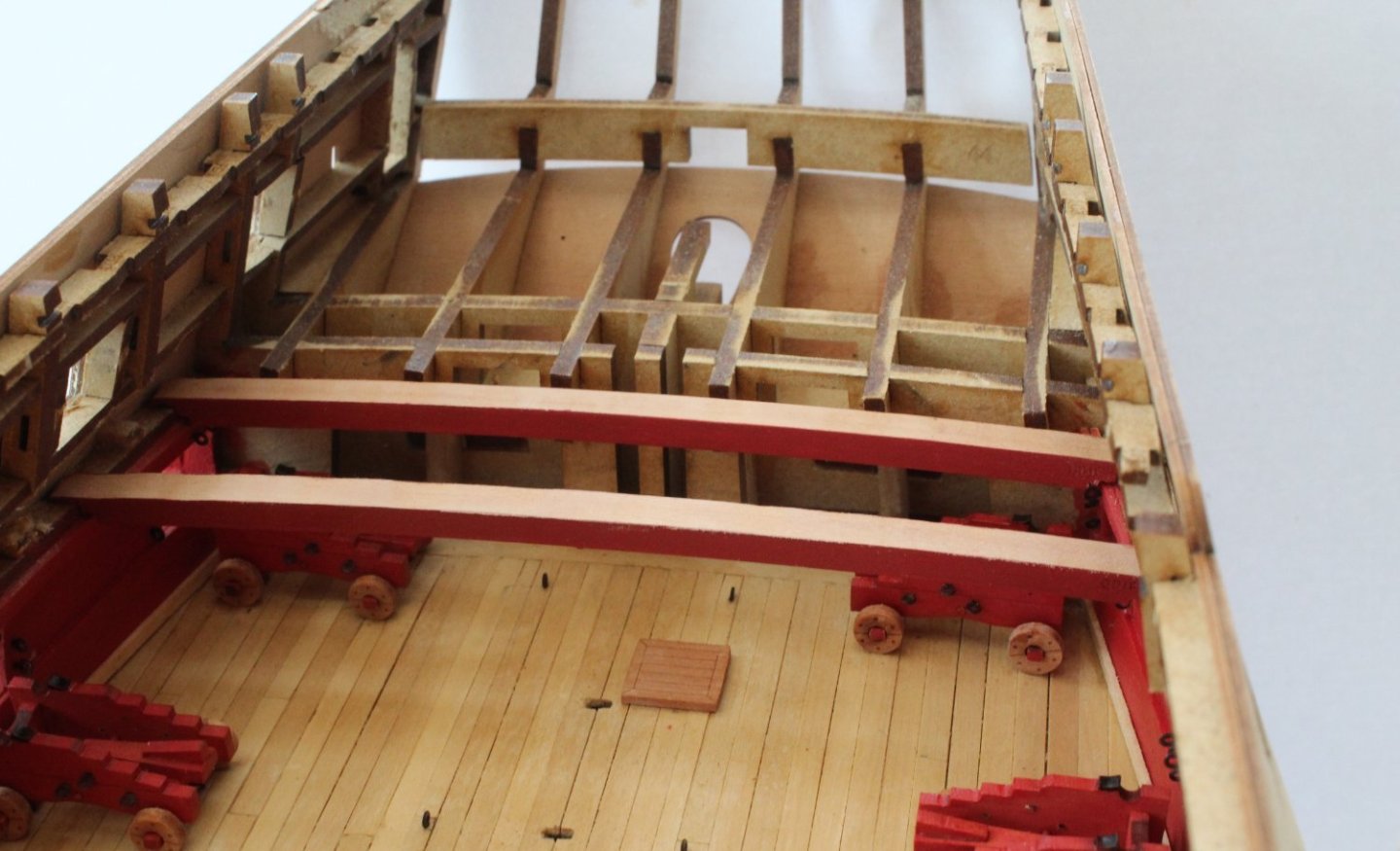
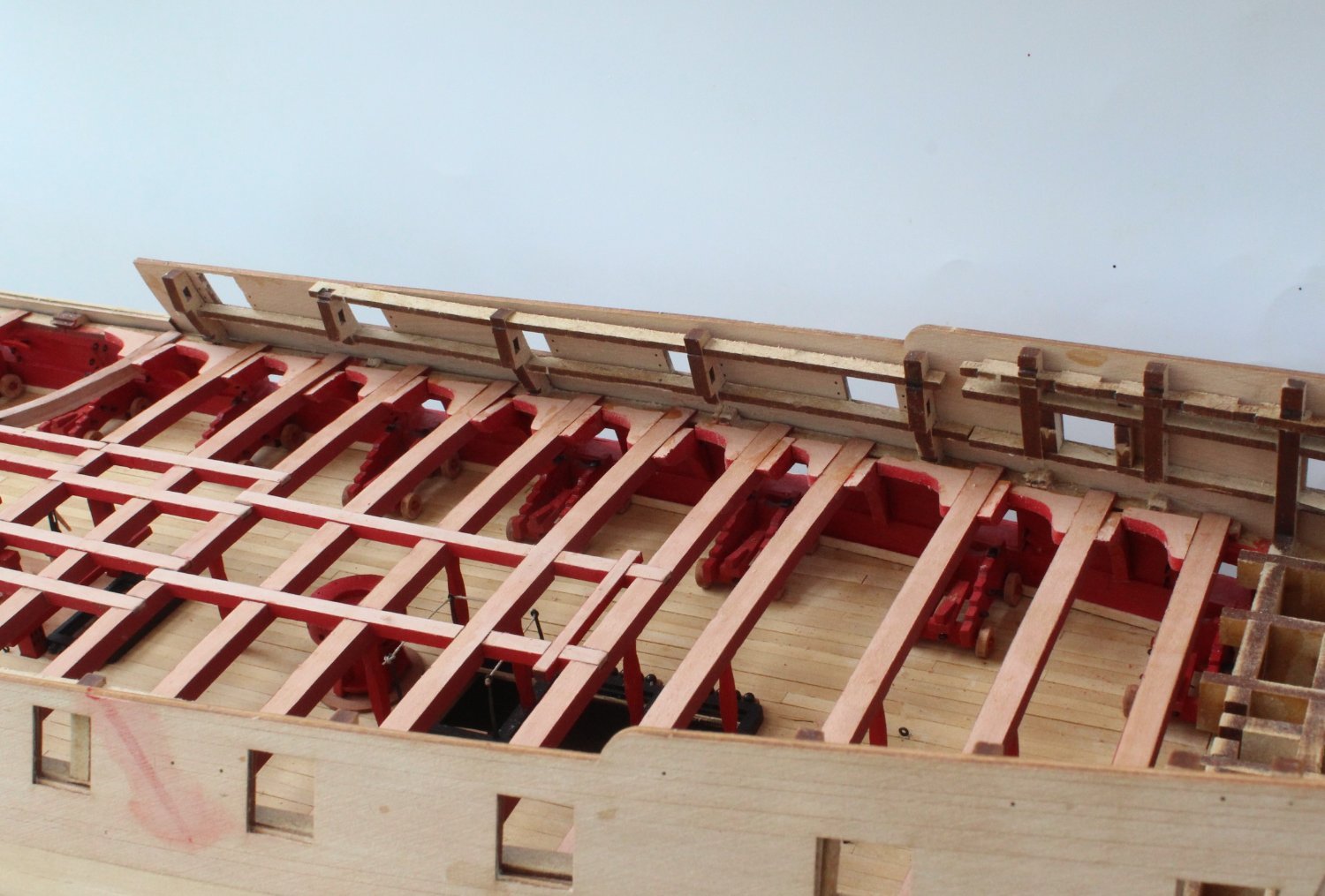
Hanging and Lodging Knees
There is quite a bit of work required to prepare and fit the hanging and lodging knees. These are option parts to fit as, once the upper decks have been fitted, they will difficult to see. In retrospect I wish I had taken time to check and modify the various hanging knees before the deck beams were glued in place as I think it would have made the task easier.
I started with the forecastle area. Once the laser char had been removed, varnish was applied to the areas to be painted. A couple coats of flat red was then brushed on once the varnish had dried.
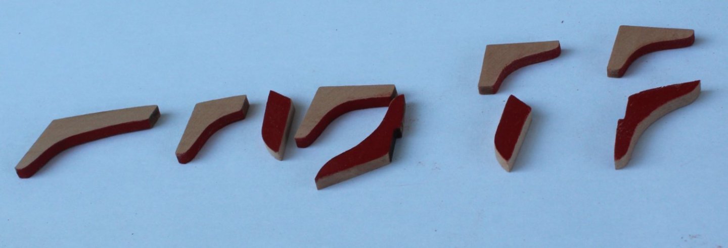
It was then a case a fitting the various knees, noting I did have to trim / shape the hanging knees.

As can be seen below I did not make a great job of all the knees. Given the deck will be sat on top I am not too bother by this.
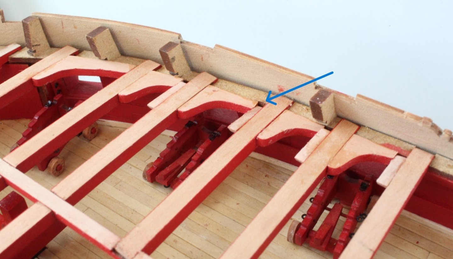
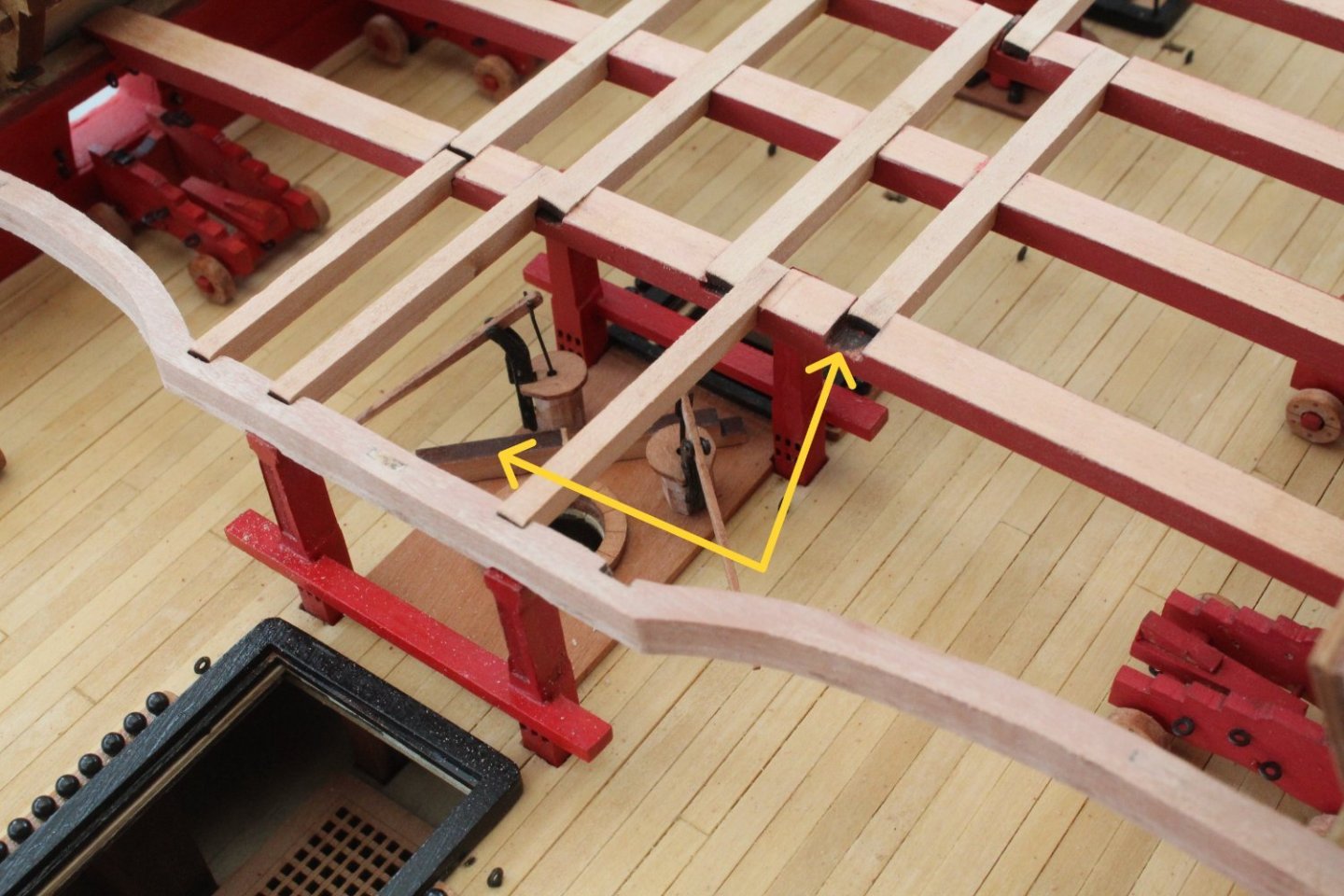
There are three knees per side to be fitted to the boat beams. I opted to only fit the middle one (blue arrow) as the others were a bit close to some cleats (yellow arrows) and I was a bit concerned that it may hinder the rigging.
Moving on to the quarterdeck area the knees have had the laser char removed and varnish has been applied to the painted areas. These will now need a little bit of time to allow the varnish to dry before they can be painted and fitted.

-
-
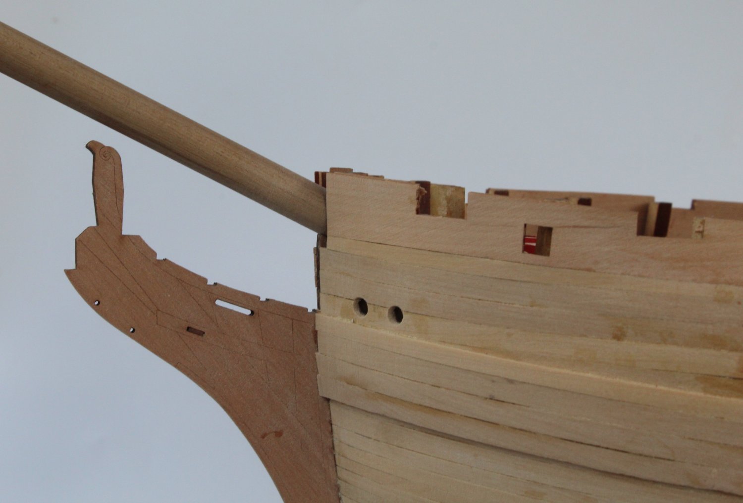
Bowsprit Test Fit
Before gluing the forecastle deck beam in place I did a trial fit of the bowsprit. I thought it would be easier to modify the elongated hole in the UD01 deck beam off the hull, if required. Fortunately the 10mm dowel slotted in without any issues so I was able to glue the deck beams in place.

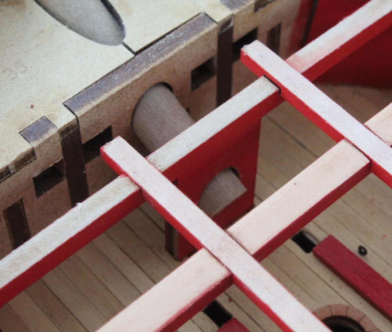
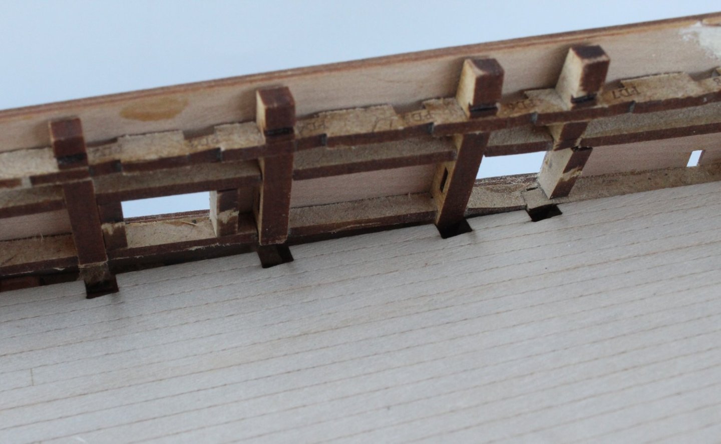
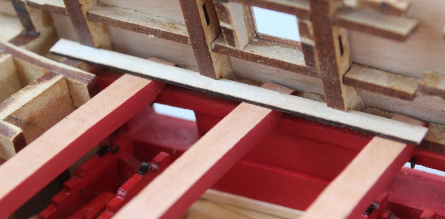
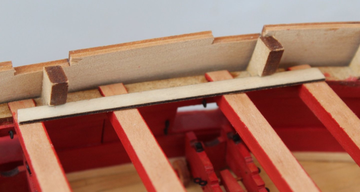
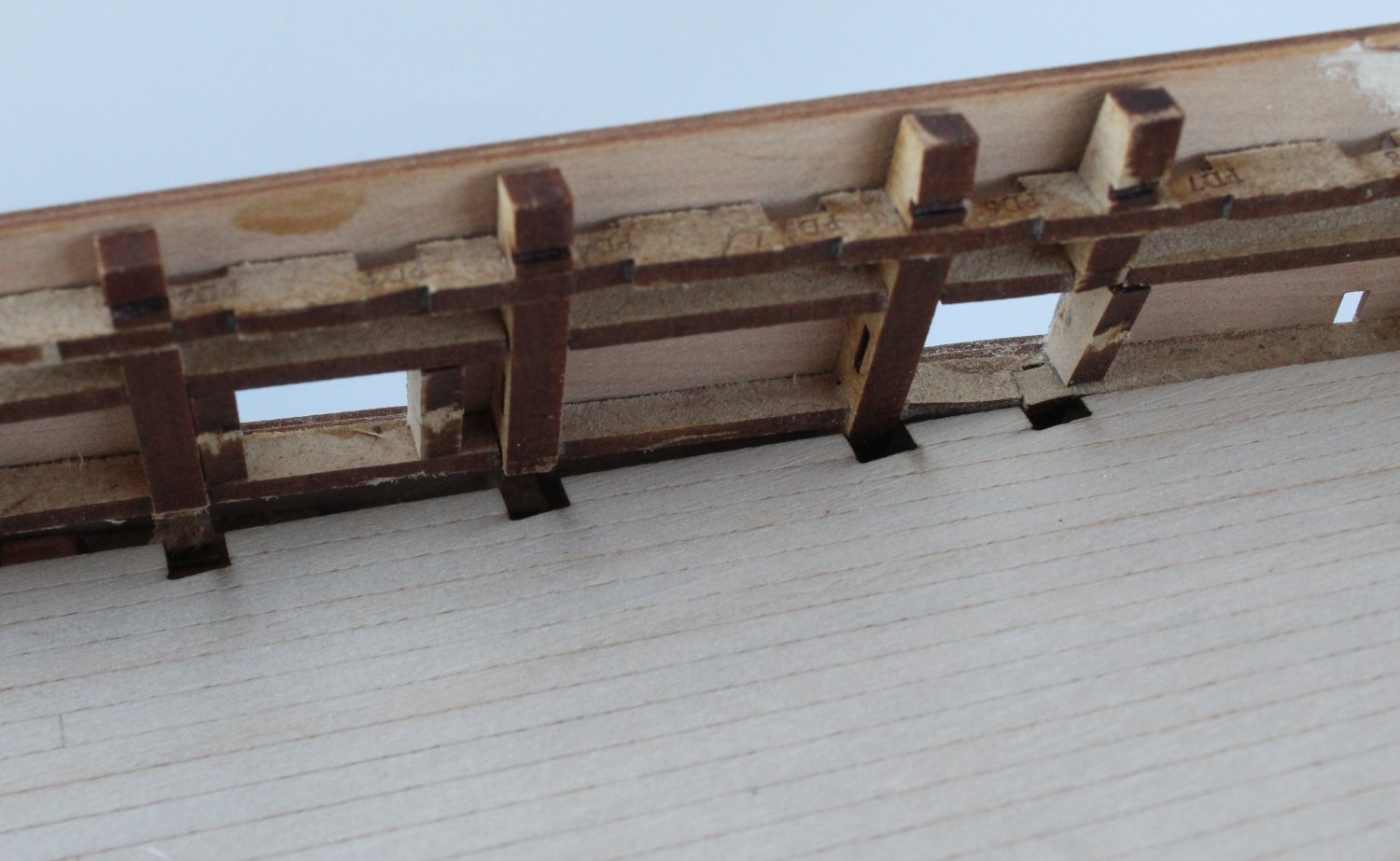
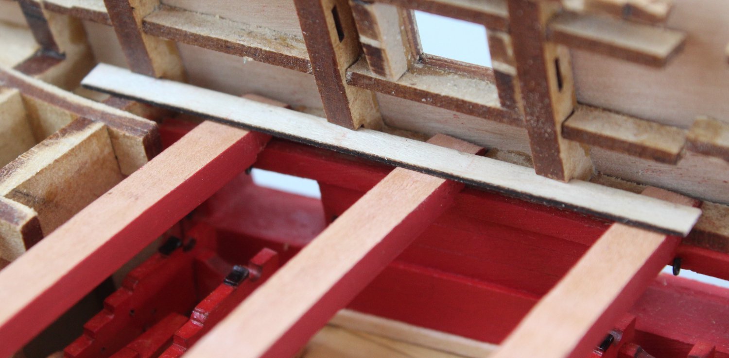
Checking Deck Pattern Slots
The bulkhead ears have slots which will be used to help locate the upper deck pattern(s) in the correct place. With the deck beams in situ I thought it would be sensible to check the slots, using a scrap bit of material. Apart from one slot on the forecastle end everything looked good. I had not noticed that one end of the deck beam (UD03) was not fully engaged in the locating slots on the left hand side. I have been able to make a fix to resolve this issue in readiness for fitting the deck pattern.
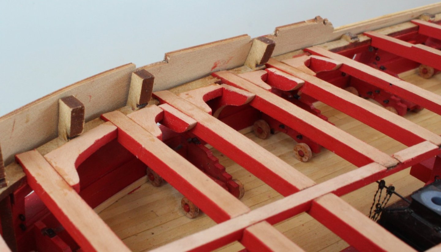
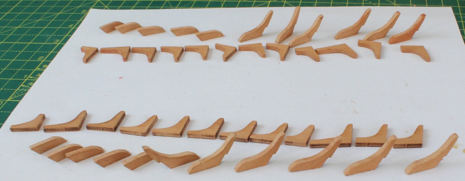
Lodging Knees
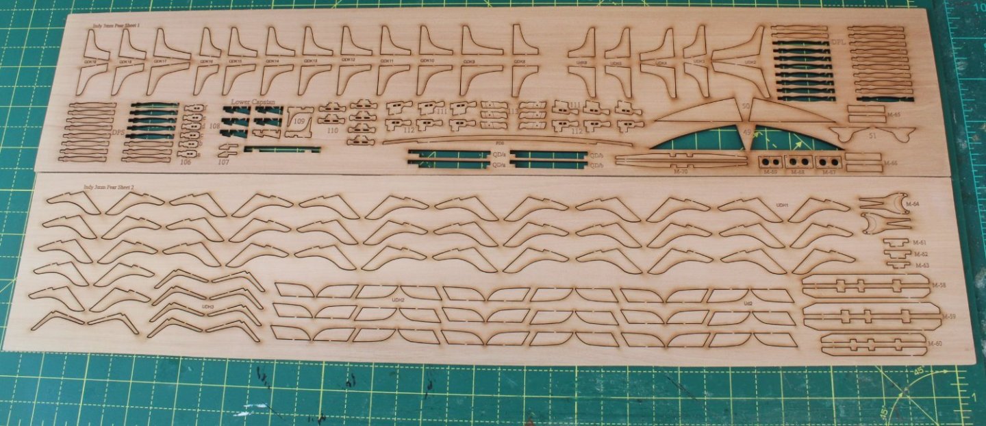
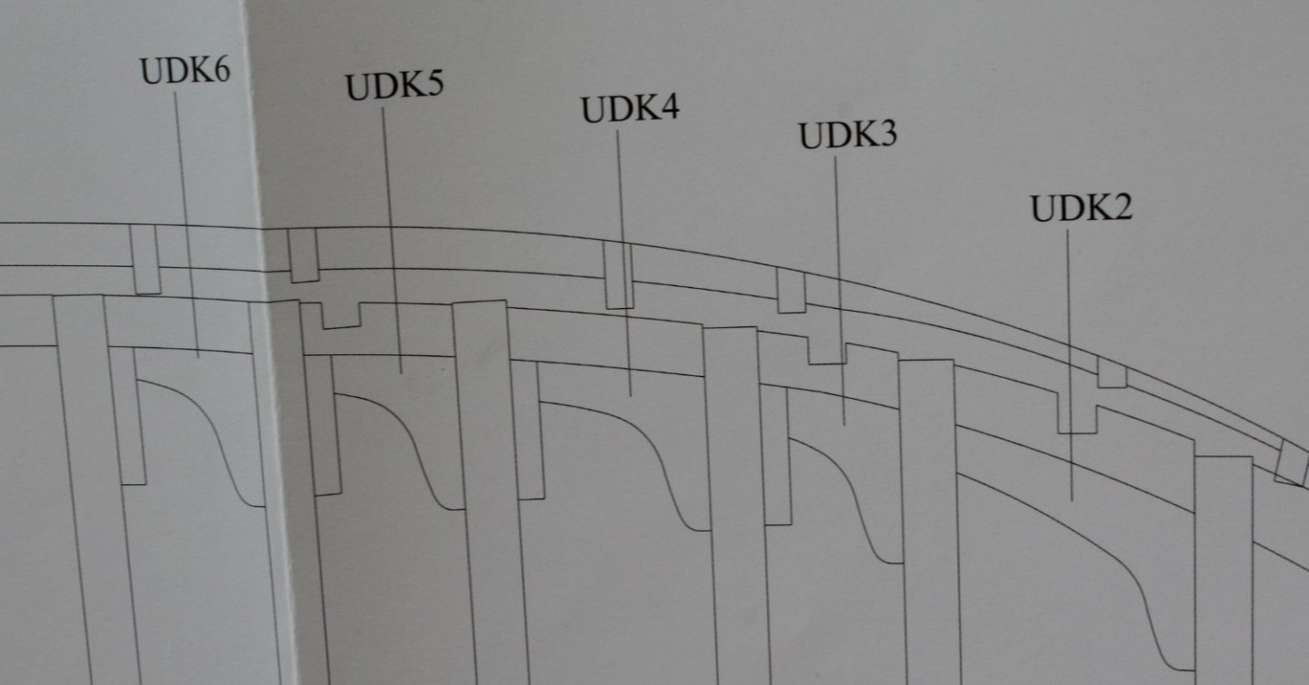
Turning my attention to the lodging and hanging Knees I have the relevant plan sheet hanging up on the wall for reference and the two pear wood sheets with all the various knees on my workbench,
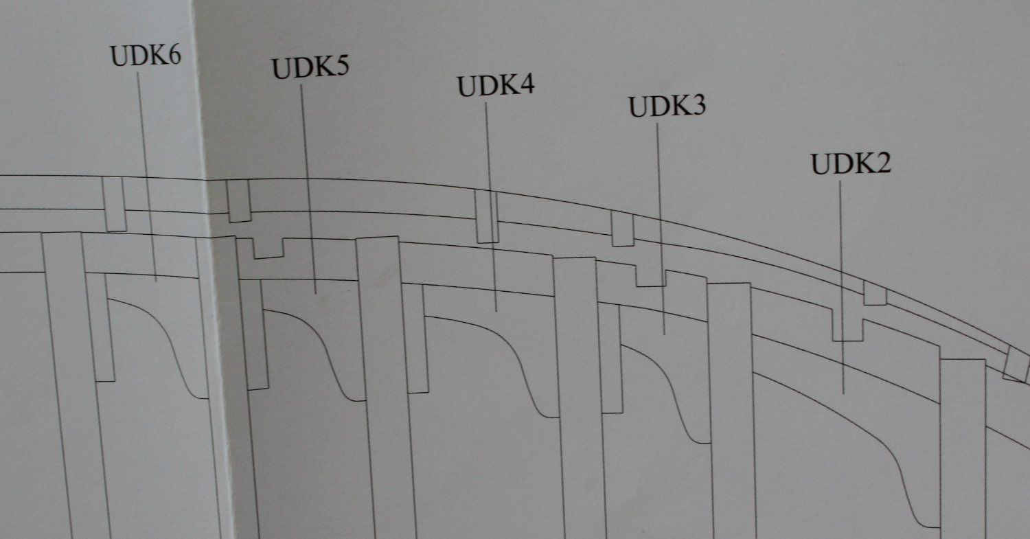
Starting at the bow end the various lodging knees are indicated on the plan sheet, as shown below. The hanging knees are also indicated on the plan sheet on the other side of the hull (not shown in the photo below)
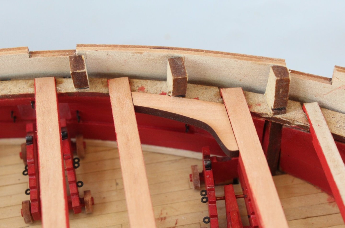
An initial test fit of the first lodging knee looks good. Laser char removal and painting required before it can be glued in place.
- chris watton, KentM, davyboy and 1 other
-
4
-
30 minutes ago, chris watton said:
That does look very cool!
Thank you Chris. I really like the look of the painted deck beams.
- mtaylor and chris watton
-
2
-
Upper Decks Deck Beams - Part 3
The final quarterdeck deck beam (QB08) was released from the jig and a trial fit was undertaken. As can be seen in the photo below there were no installation problems. The slots at the bottom of QD08 aligned perfectly with the top of the bitts. The various interlock patterns also were a good fit, noting the left and right edges still need to be painted.
After a few minutes work with my rotary sanding tool the laser char was removed.
I had not noticed when taking the next photo but one of the patterns had fallen to the gundeck.
The left and right edges of the interlocking patterns were, after a coating of WOP, were painted red. Once the paint had dried the quarterdeck deck beams, interlocking patterns and pillars were glued in place.
It was more of the same as the forecastle and gangway deck beams had the laser char removed and then were painted and test fitted. As expected there were no installation issues. Before these items are glued in place there are 6 pillars to be fitted. The pillars will need to be checked for length and trimmed as necessary and then painted. I have added a couple of photos of the forecastle and gangway deck beams in place.
And a final photo of all the deck beam to finish of this build log post.
- Blue Ensign, rlwhitt, mugje and 15 others
-
18
-
Adding The Quarterdeck Deck Beams - Part 2
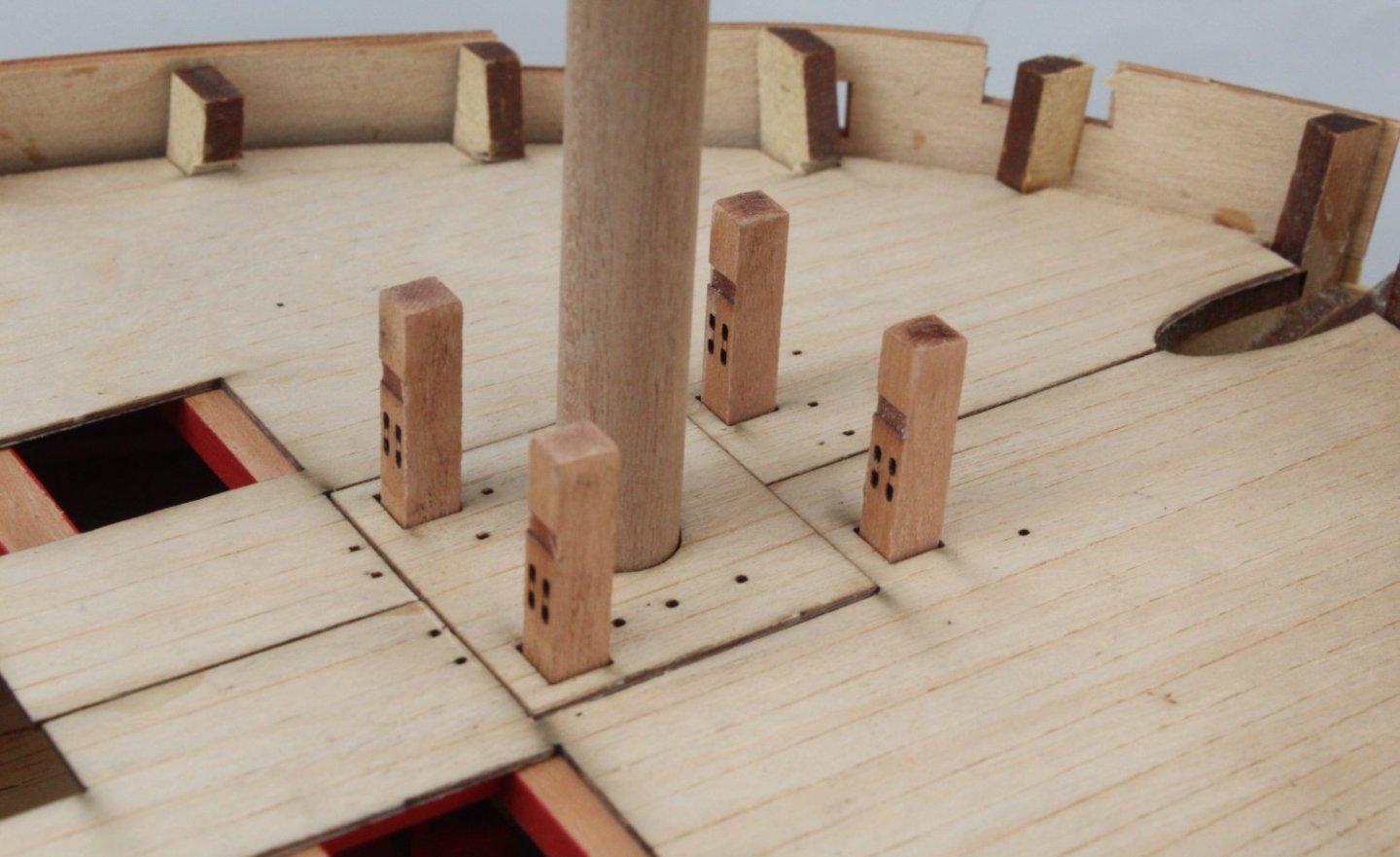
With the second quarterdeck deck beam in place the first pillar was test fitted. It did require a little bit of trimming to reduce the length so it was a good snug fit.
A few minutes later the next pillar was trimmed and test fitted.

In total there are 5 pillars to fit, 2 x long type and 3 x short type. Once they were all trimmed to size they were painted flat red. All looks good.

With the tape removed the remaining quarterdeck deck beams were slotted in place.
Next the interlocking parts were added.
The final photo shows three of the painted pillars.
The next task will be to clean up, test fit and paint the final deck beam (QD08), which was the deck beam which assembled from 4 separate patterns and bent to shape using a kit supplied jig. Once that has been completed everything can be glued in place.
Slow and steady in my mantra for this build.
-
Adding The Quarterdeck Deck Beams
This is quite an involved task comprising several different steps. As you will have noted in my previous deck beams post the first task was to remove the laser char from the top edges. I used my trusty rotary tool for this task and then a fine graded sanding stick to remove any remnants.
The next step, which is not strictly necessary, was to dry fit the various items (off hull). This is to make sure that:
a) I have located all the required parts.
b) To understand how and where each part is to be fitted as there is an interlocking arrangement.
c) To make sure the various parts will fit in their respective locating slots.
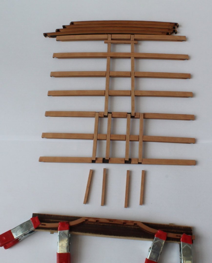
In the photo below I have gathered all the parts and I have done a preliminary dry fit. Everything fits together very nicely. So far so good.
The front and back faces of each deck beam need to be painted flat red. The top edge is not to be painted, however. Therefore, I have added tape to the top edge of each of the deck beams.
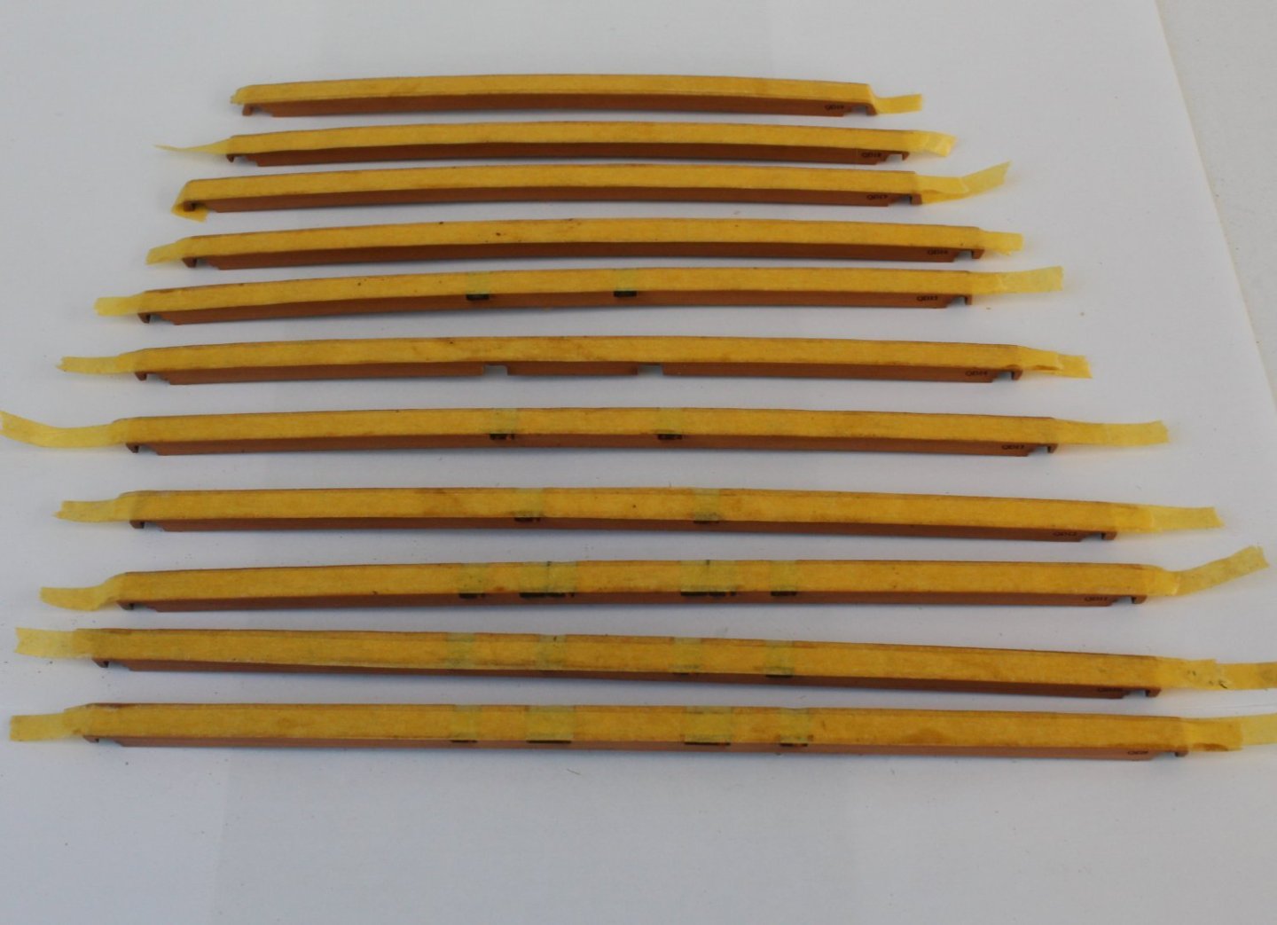
With the tape in place and the edges pressed in tight I added a couple of coats of varnish to the front and back facing edges. The varnish will provide a nice base for the flat red paint and will (I hope) provide a seal to prevent any paint leakage. If there is any paint leakage it will be easy to remove with a bit of light sanding.
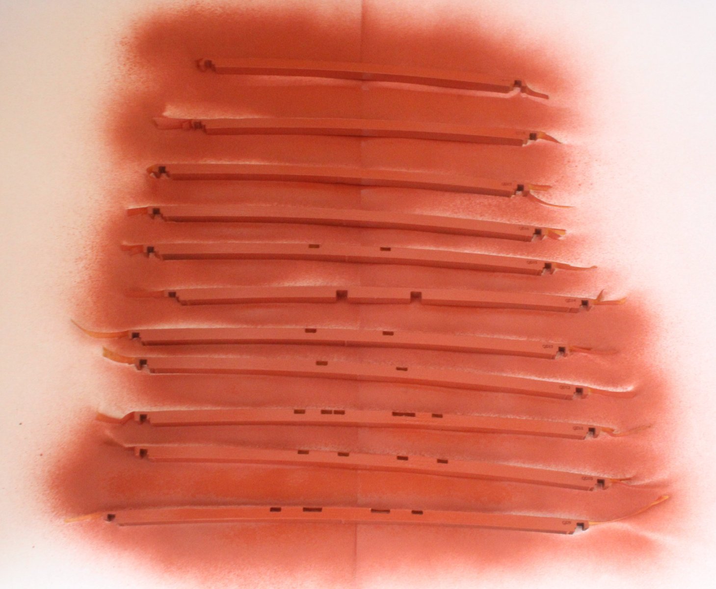
Utilising an old cardboard box, I made a simple spray-painting booth as I intend to add a red oxide primer to the deck beams before the flat red paint is added.
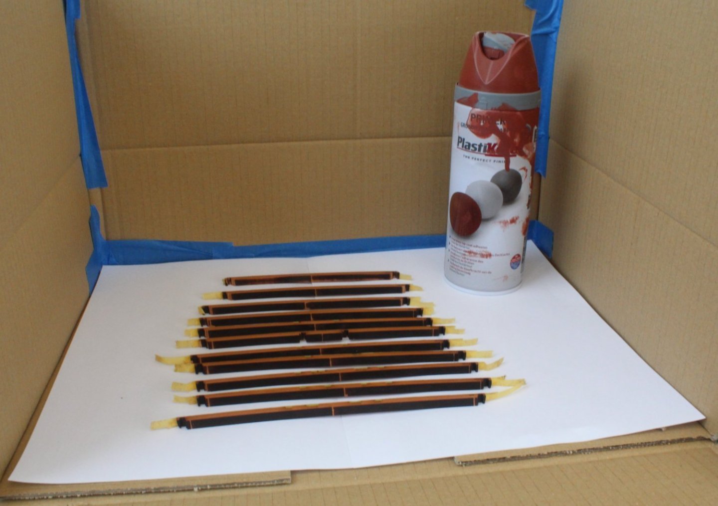
The deck beams are now sprayed with the red oxide primer.

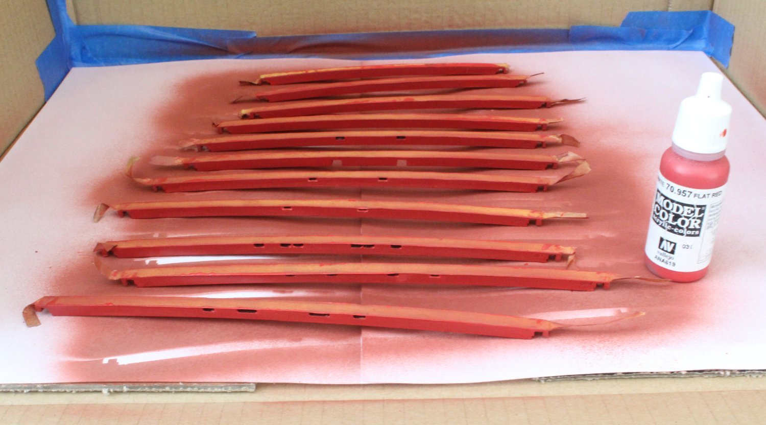
Next I brushed on three coats of flat red.

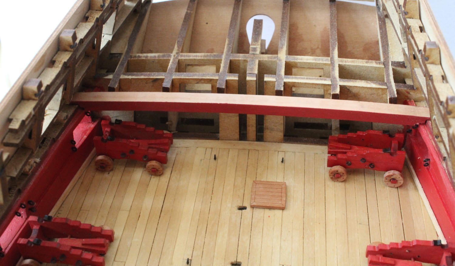
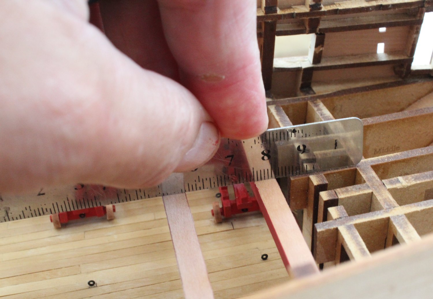
As the tape is removed from the first deck beam, I am pleased to see there has been no paint bleed. The first painted quarterdeck deck beam is then test fitted.

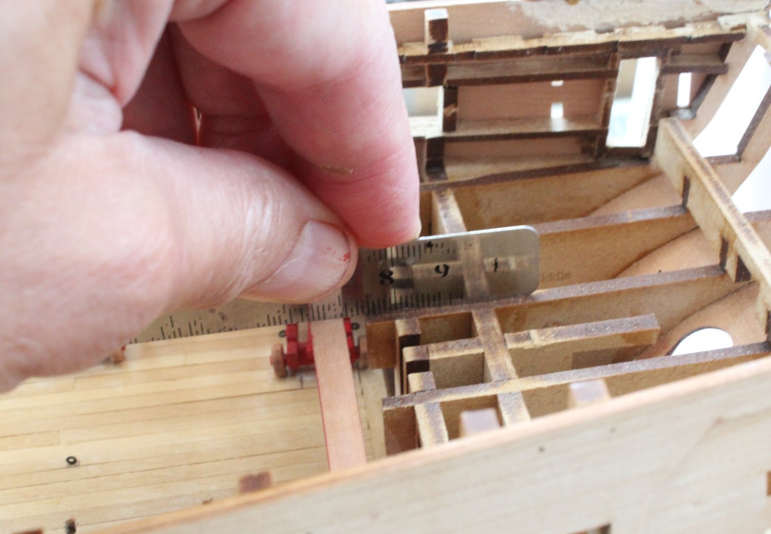
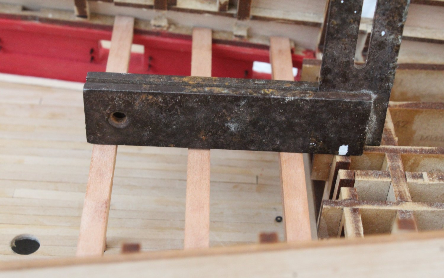
Using a ruler, the alignment of the deck beam is also checked.

The next set of photo’s shows the test fitting of the next deck beam. I will need to add the deck beam pillar to ensure it will fit snuggly under the deck beam

-
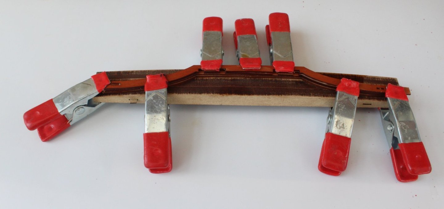
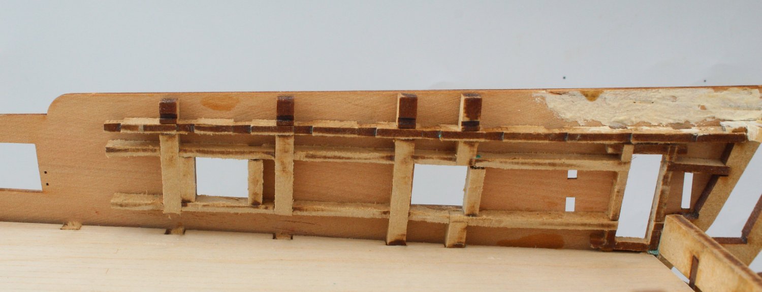
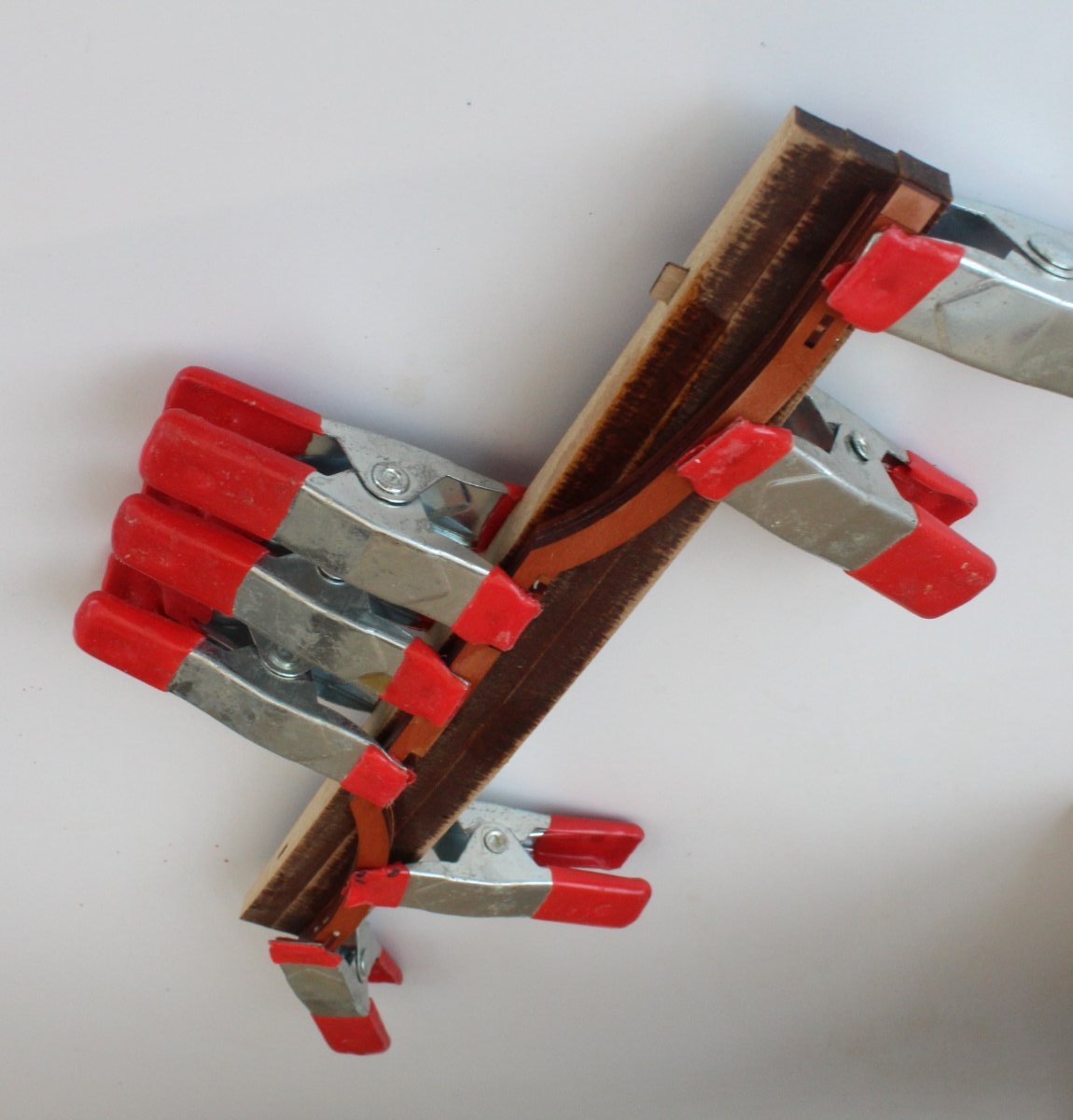
Quarterdeck Deck Beam QD08
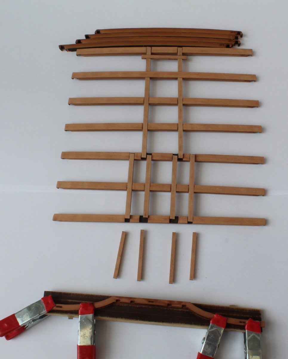
The quarterdeck deck beam QD08 comprises 4 separate patterns which have to be glued together, whilst clamped to a jig which applies a bend. In the following pictures I have just added the final QD08 pattern to the jig. The completed gundeck beam QD08 assembly will now be left clamped for the time being.

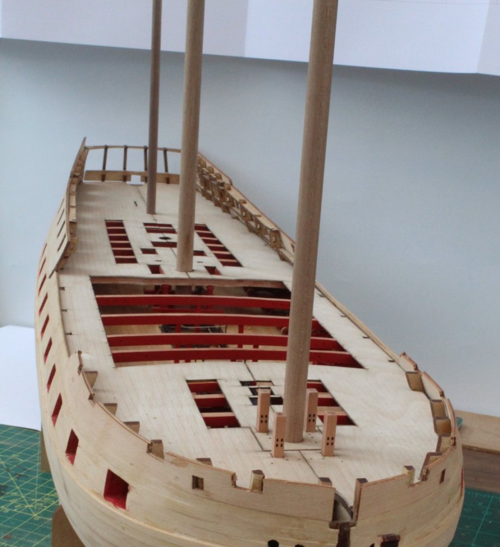
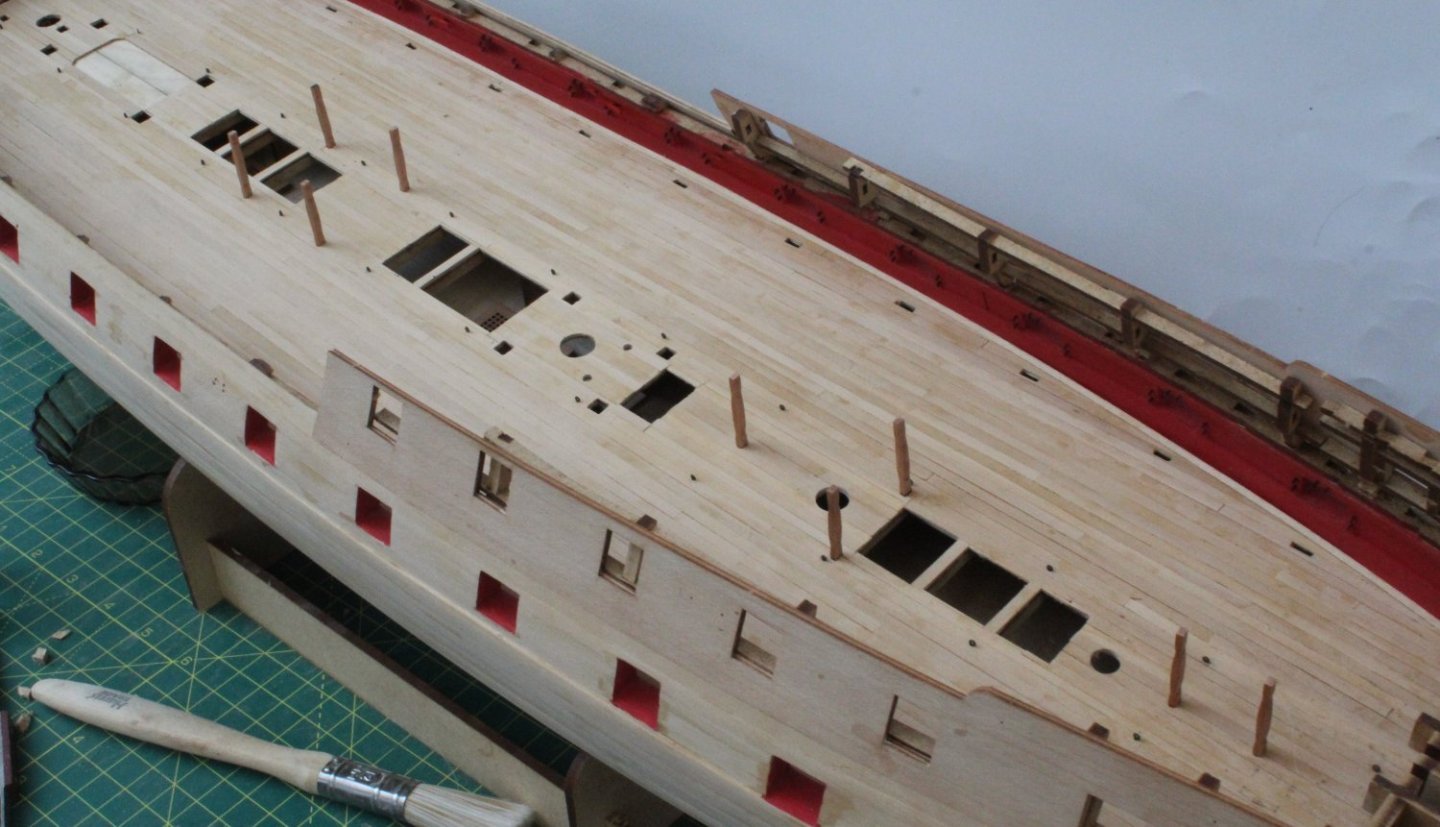
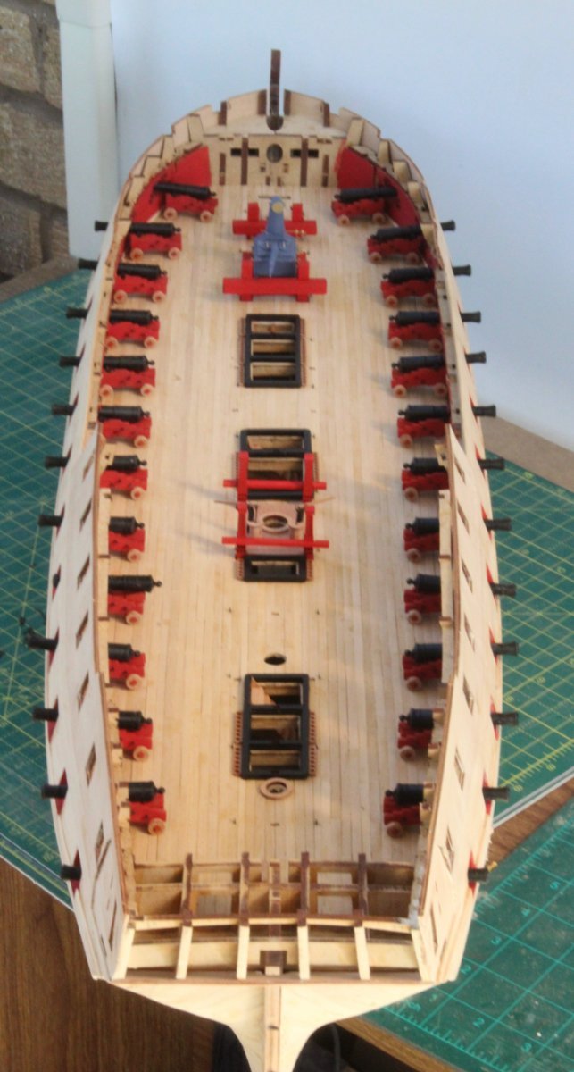
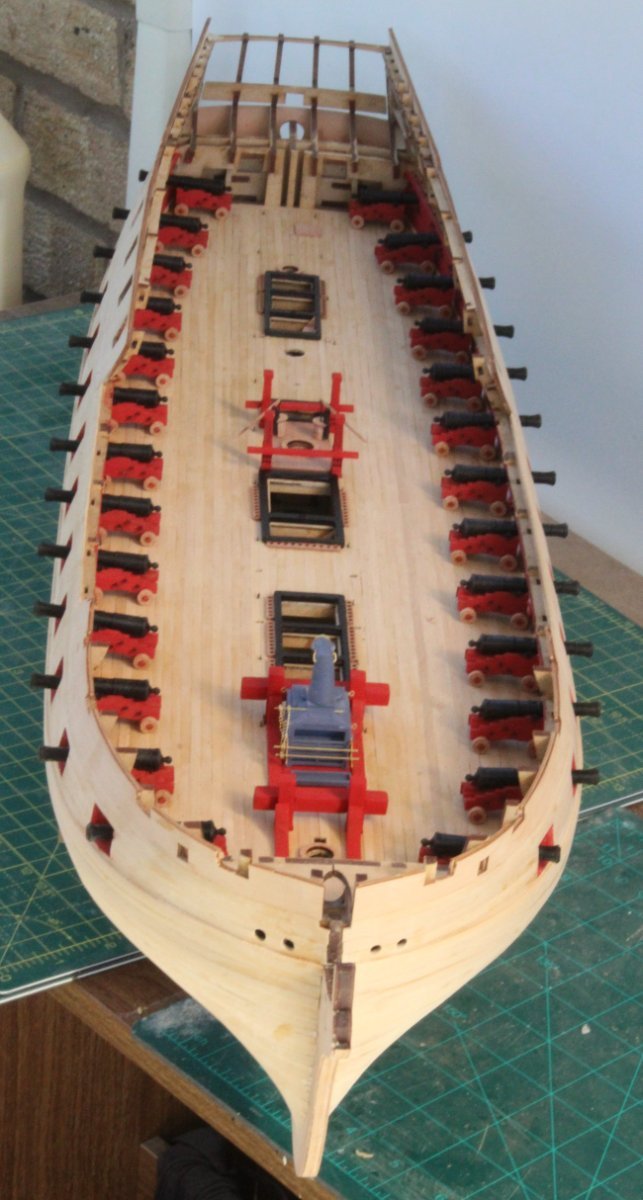
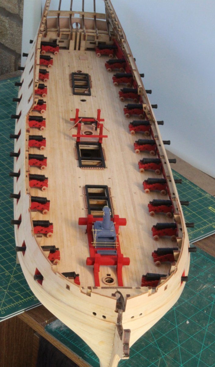
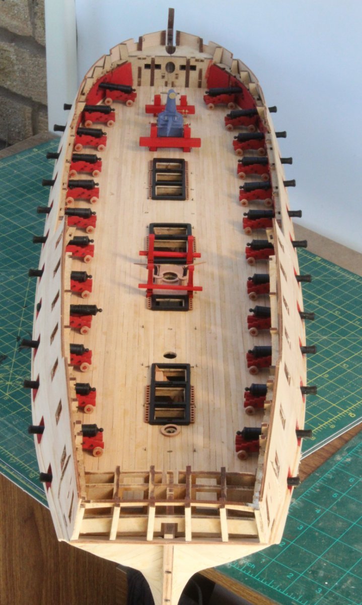
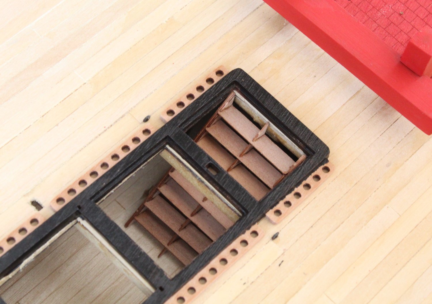
Completion of Gun Deck
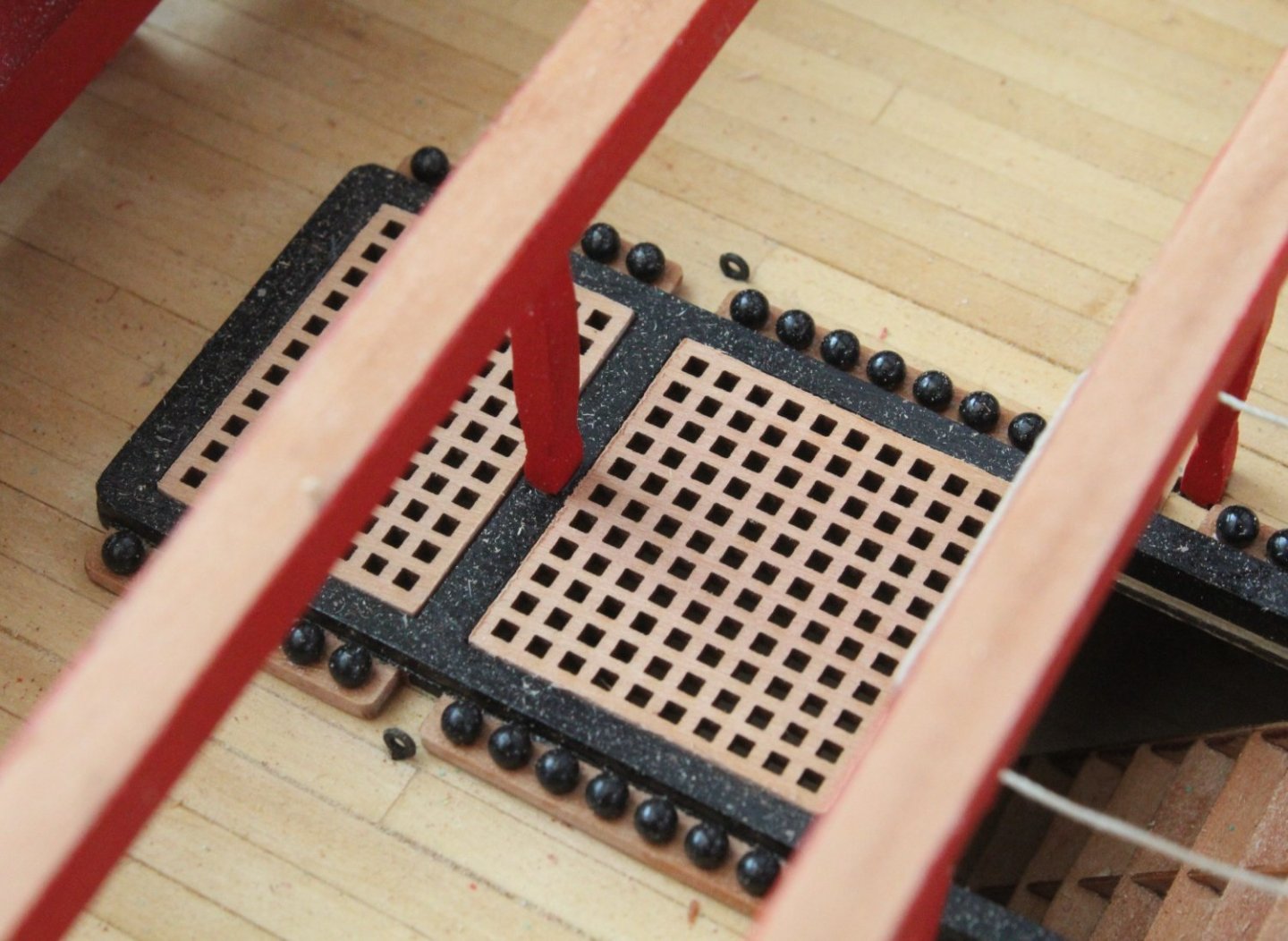
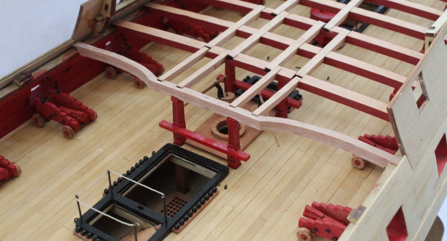
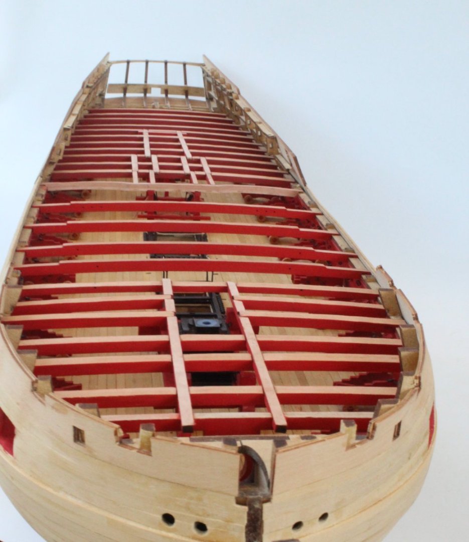
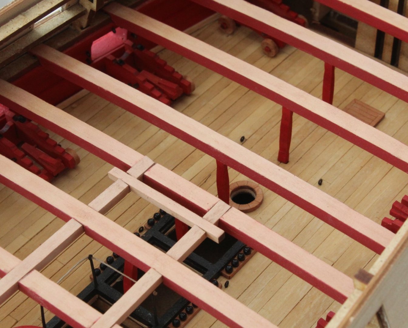
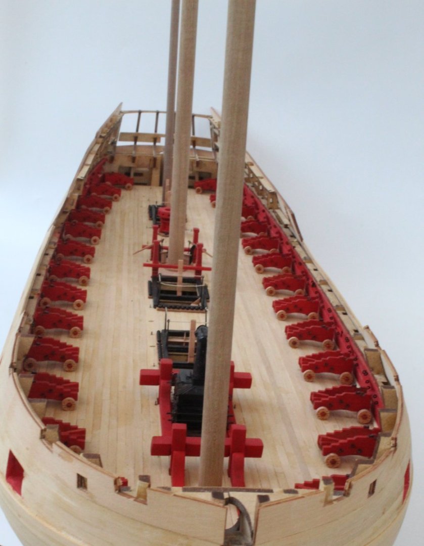
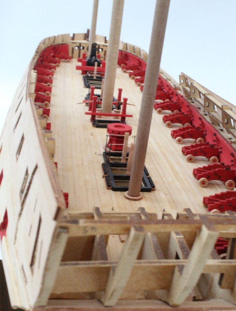
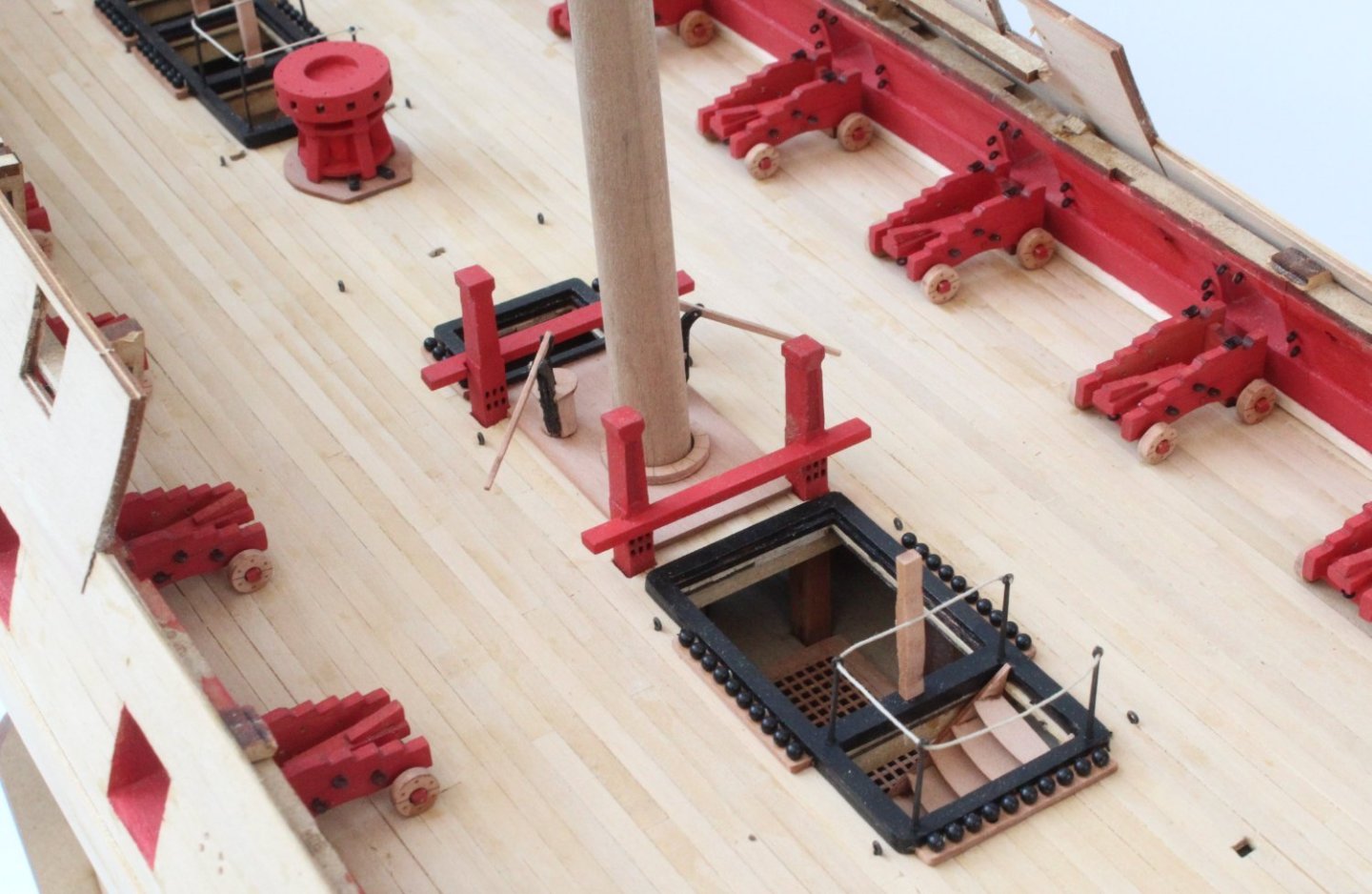
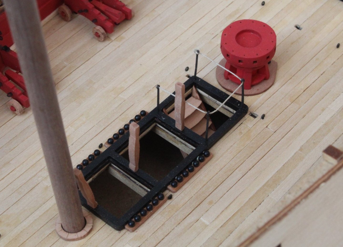
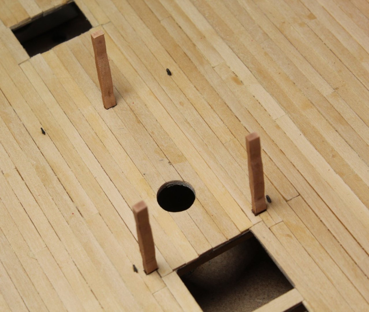
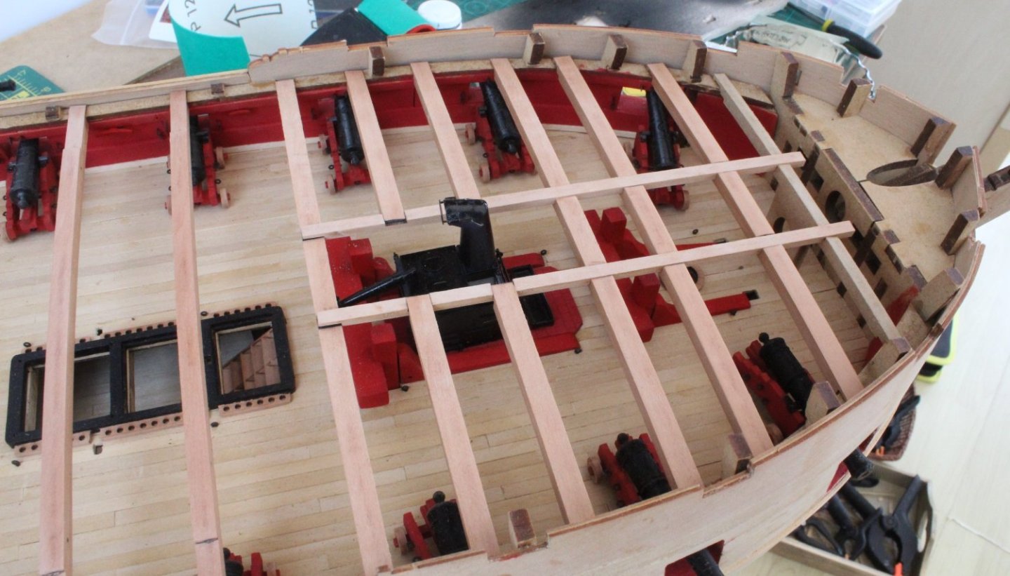
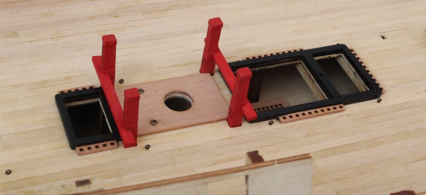
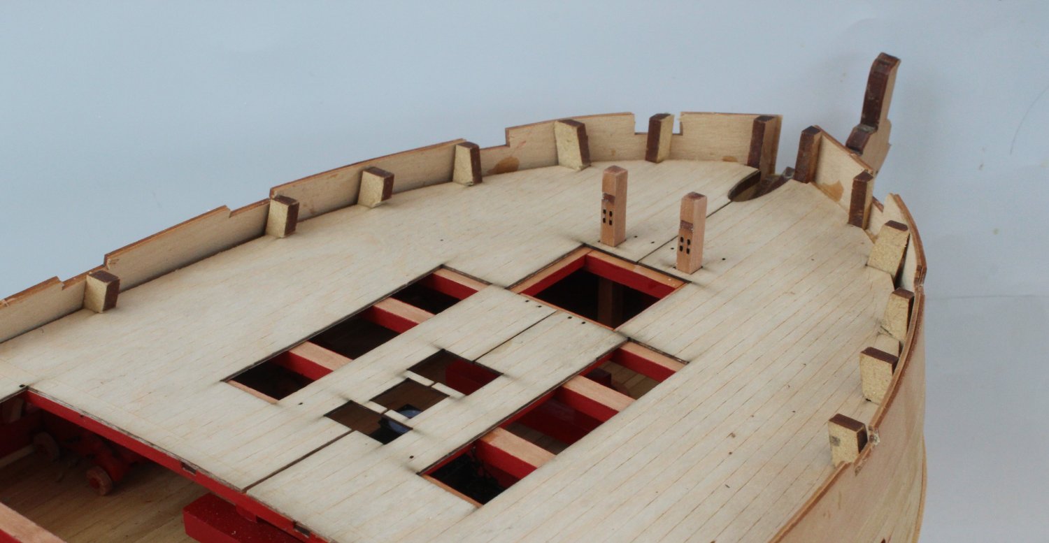
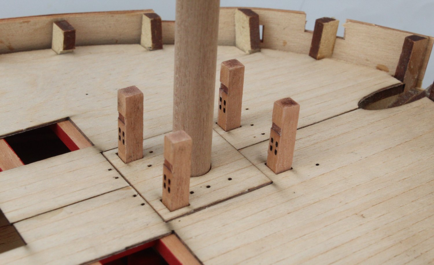
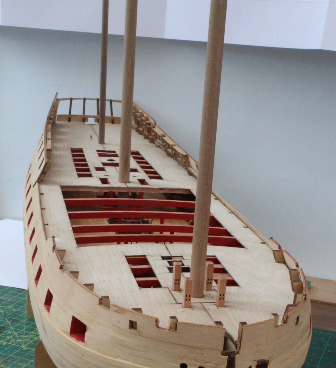
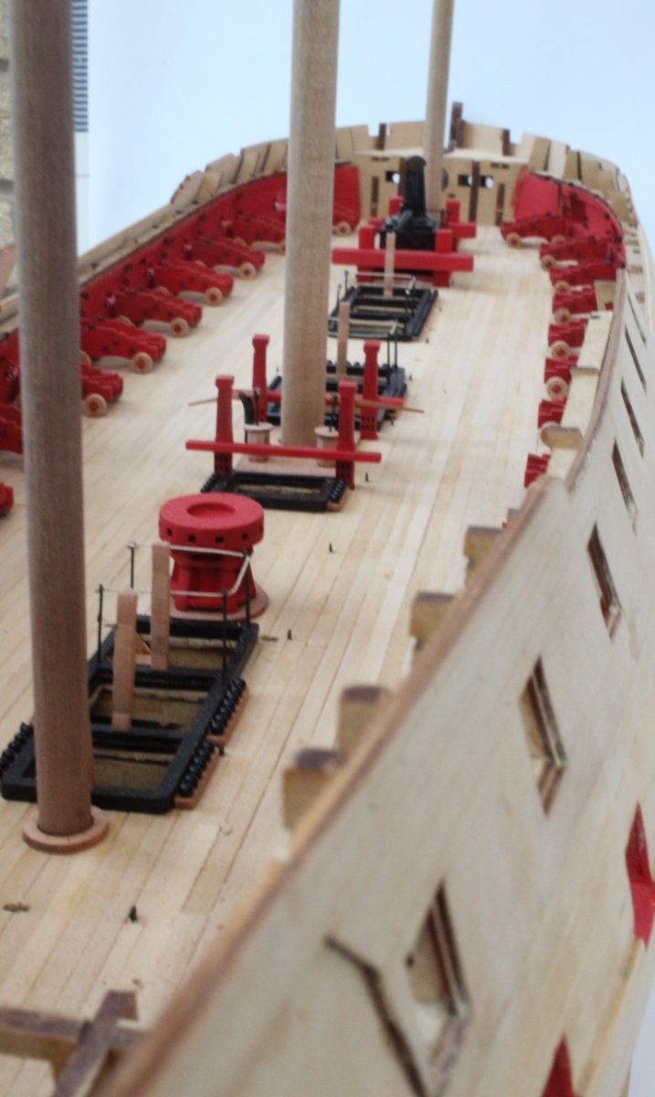
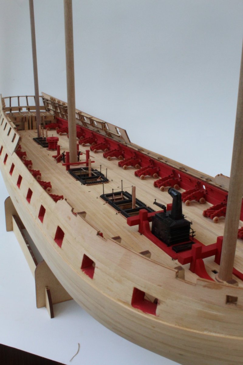
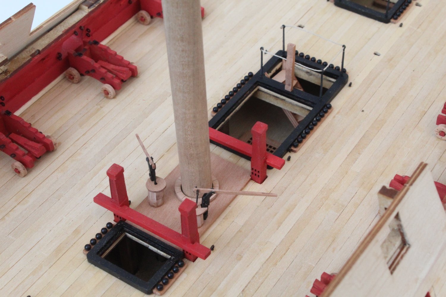
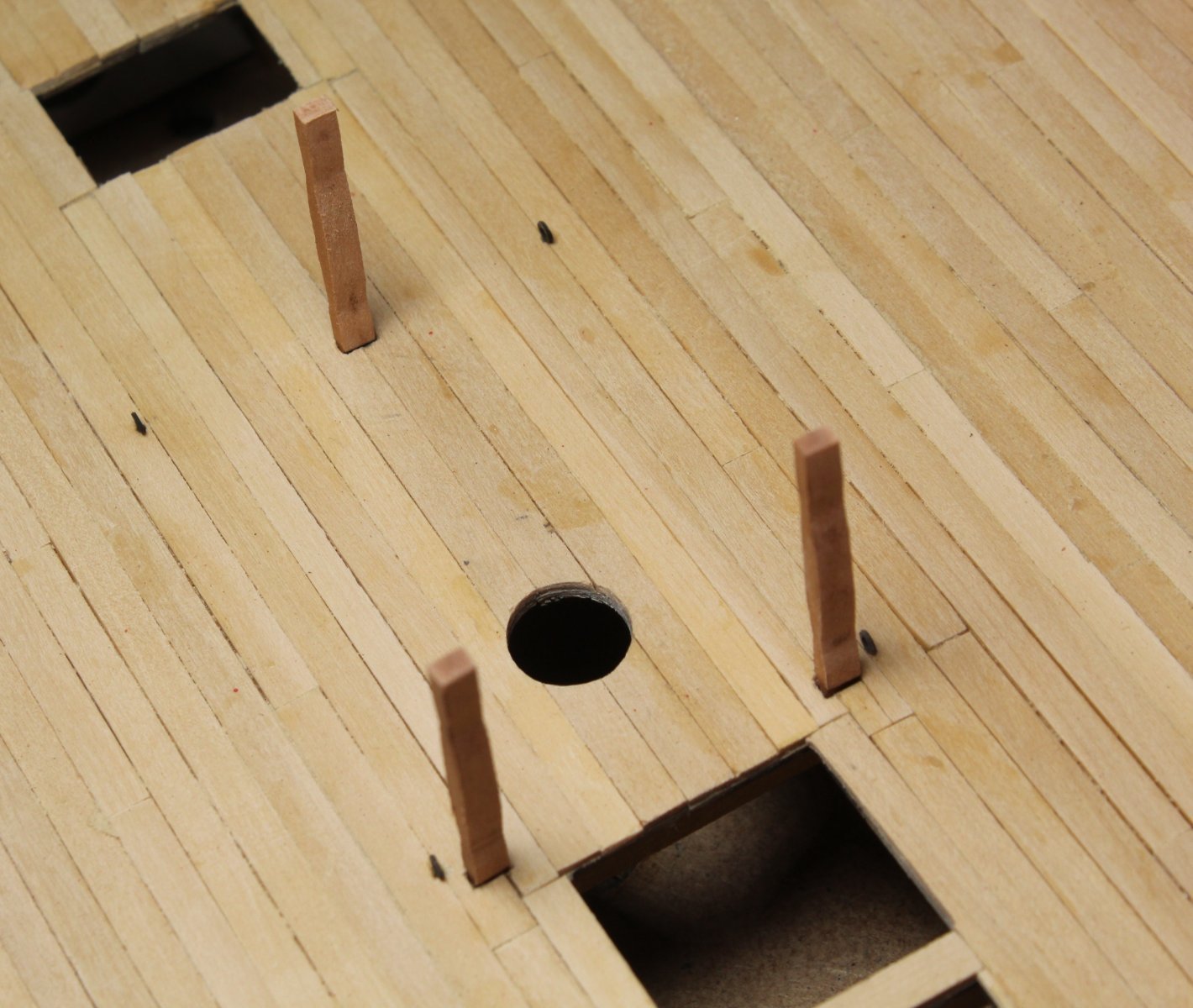
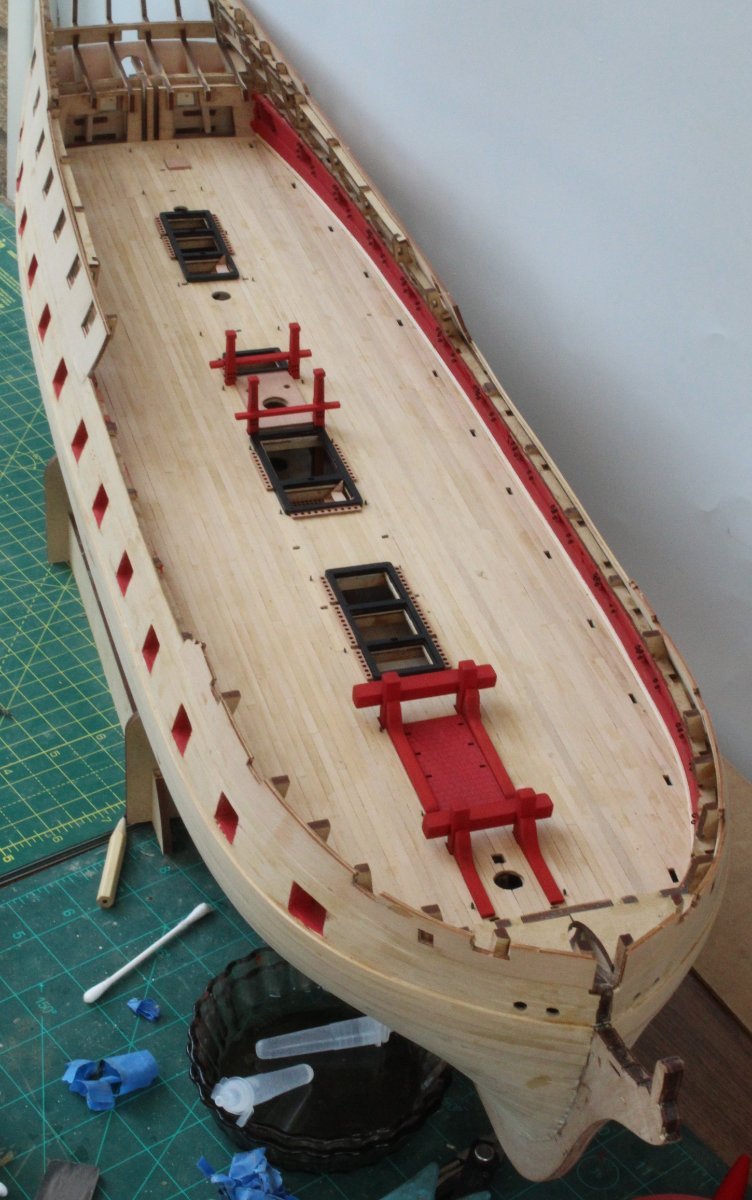
I have reached another major milestone as I have now completed the Indy build up to and including adding all the gun deck items. It was a case of taking my time adding the various gun deck items today. In the attached pictures the deck beam pillars (located on the various hatches) are only dry fitted as they will need to be checked (and trimmed) for length as the deck beams are added. I had a senior moment when setting up the Indy for the following set of photos as I forgot to add the hatch comings although I did remember to add some dowels for the fore, main and mizzen masts.


- chris watton, Ryland Craze, mugje and 7 others
-
10
-
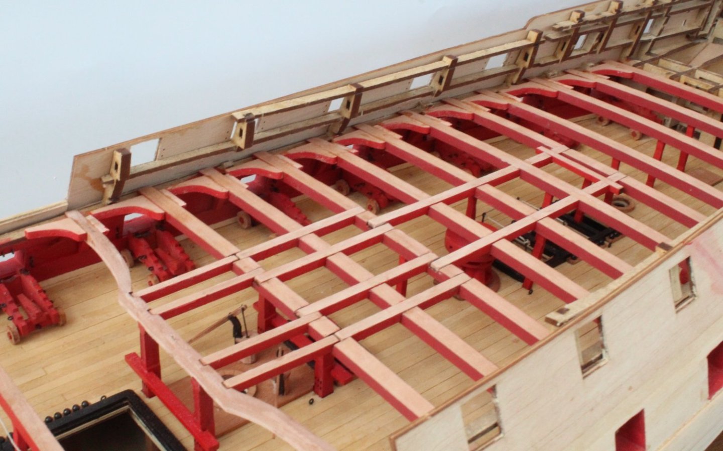
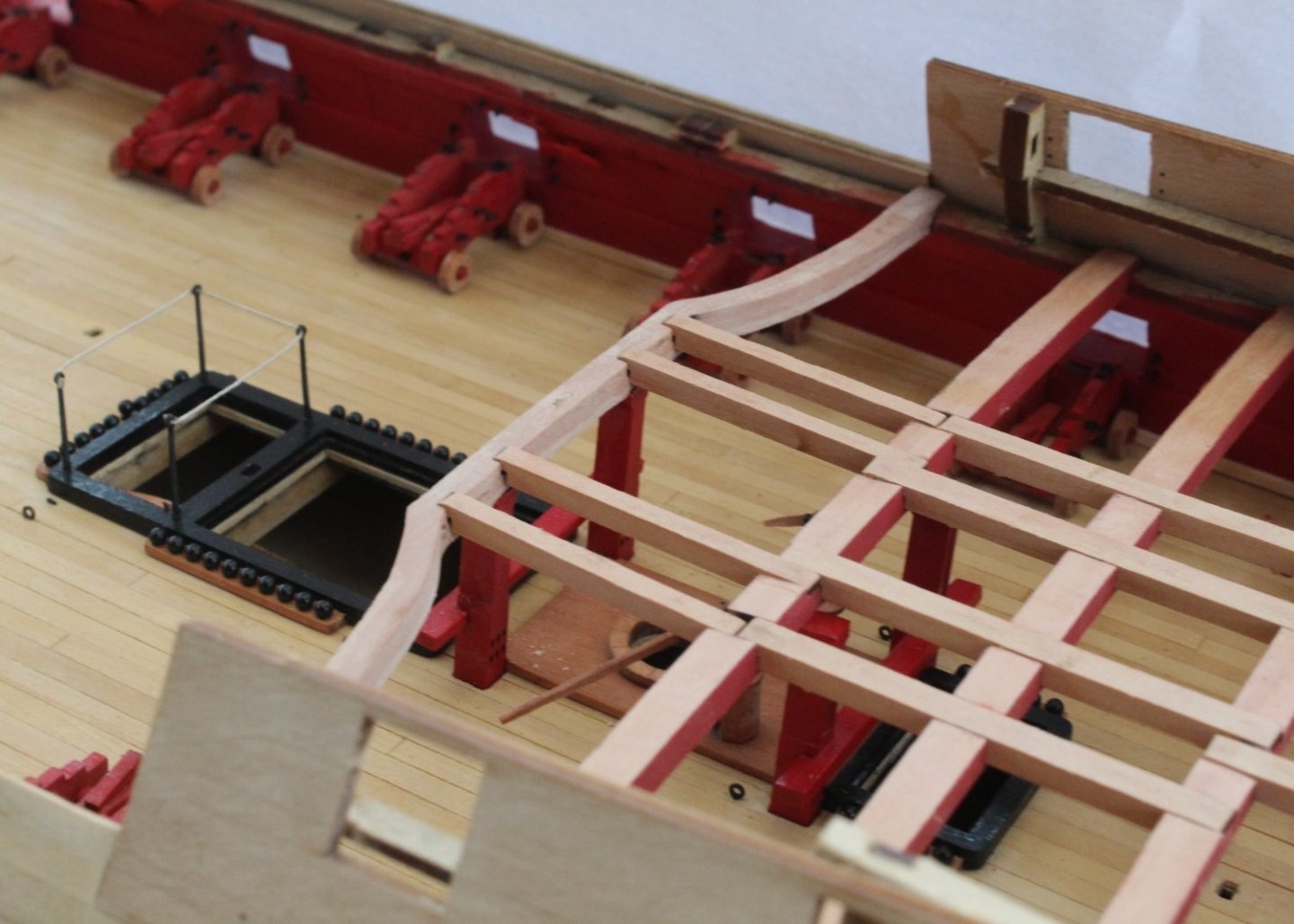
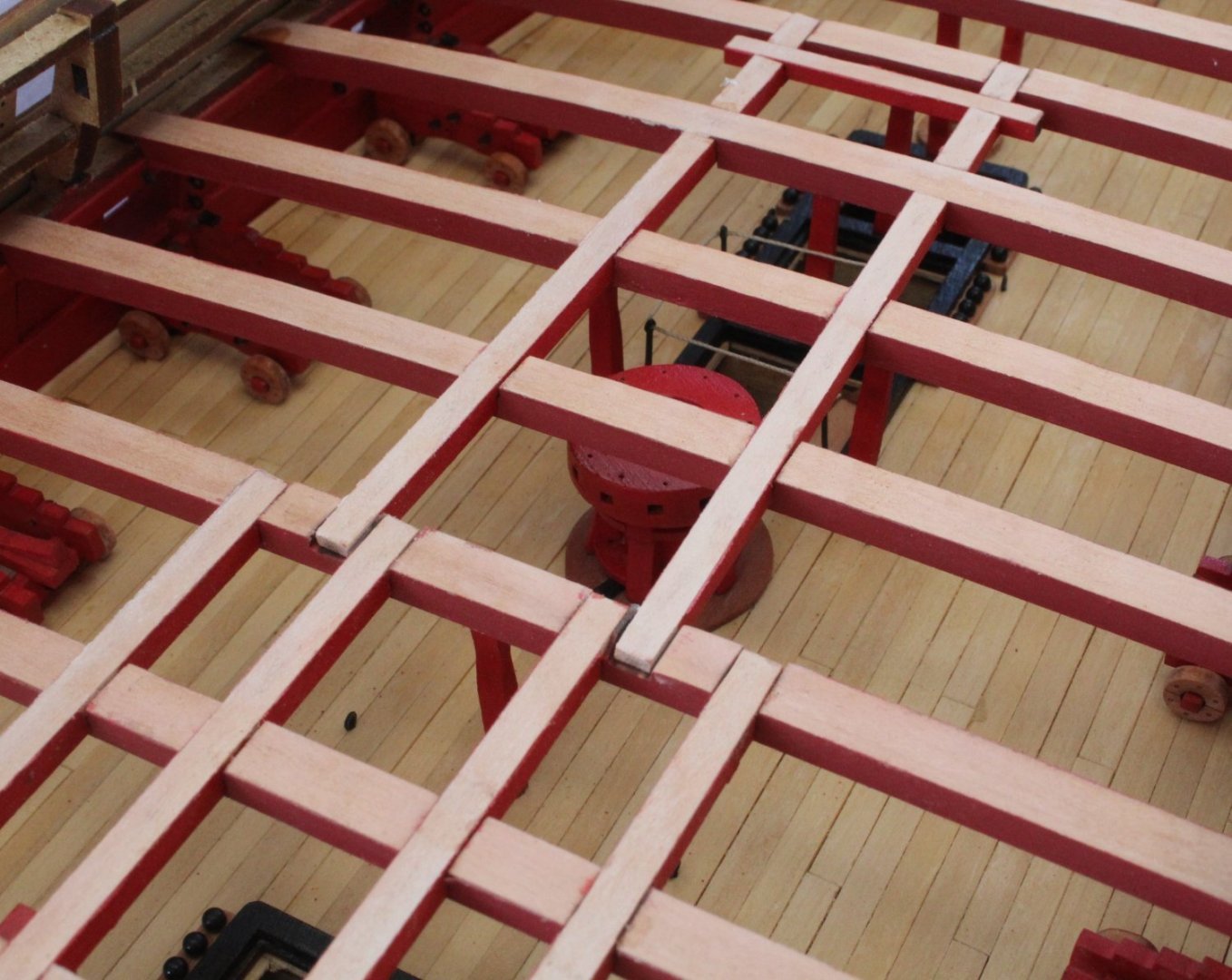
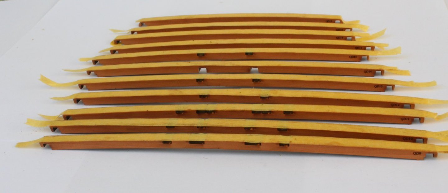
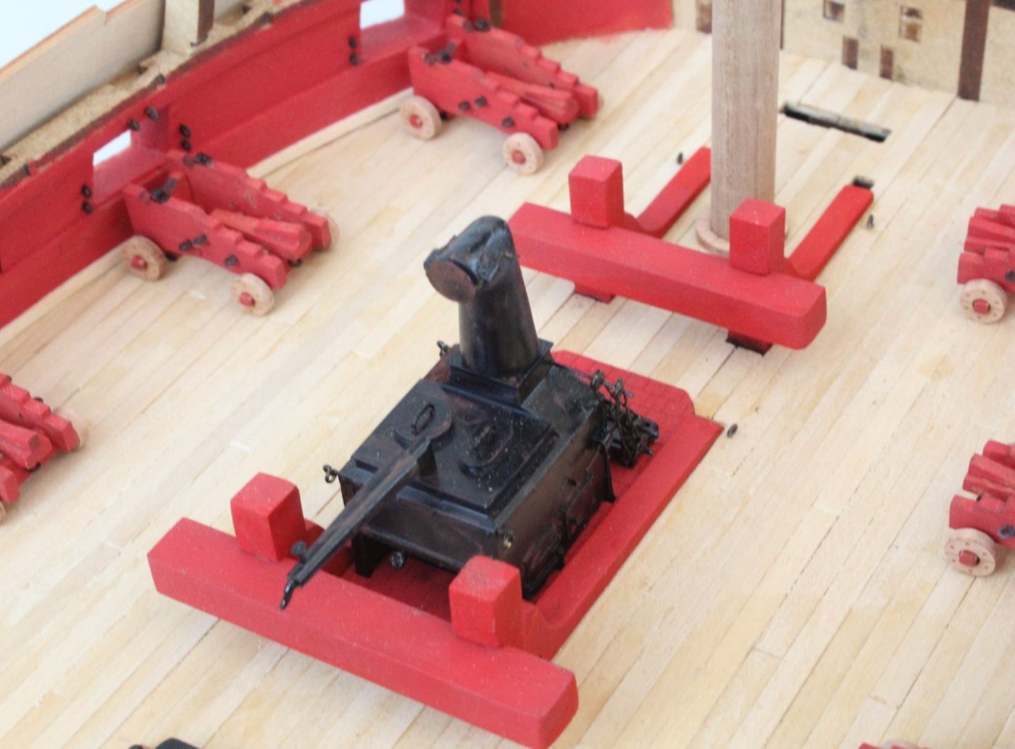
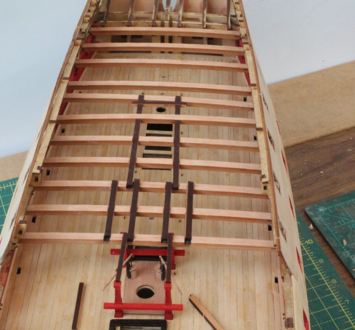
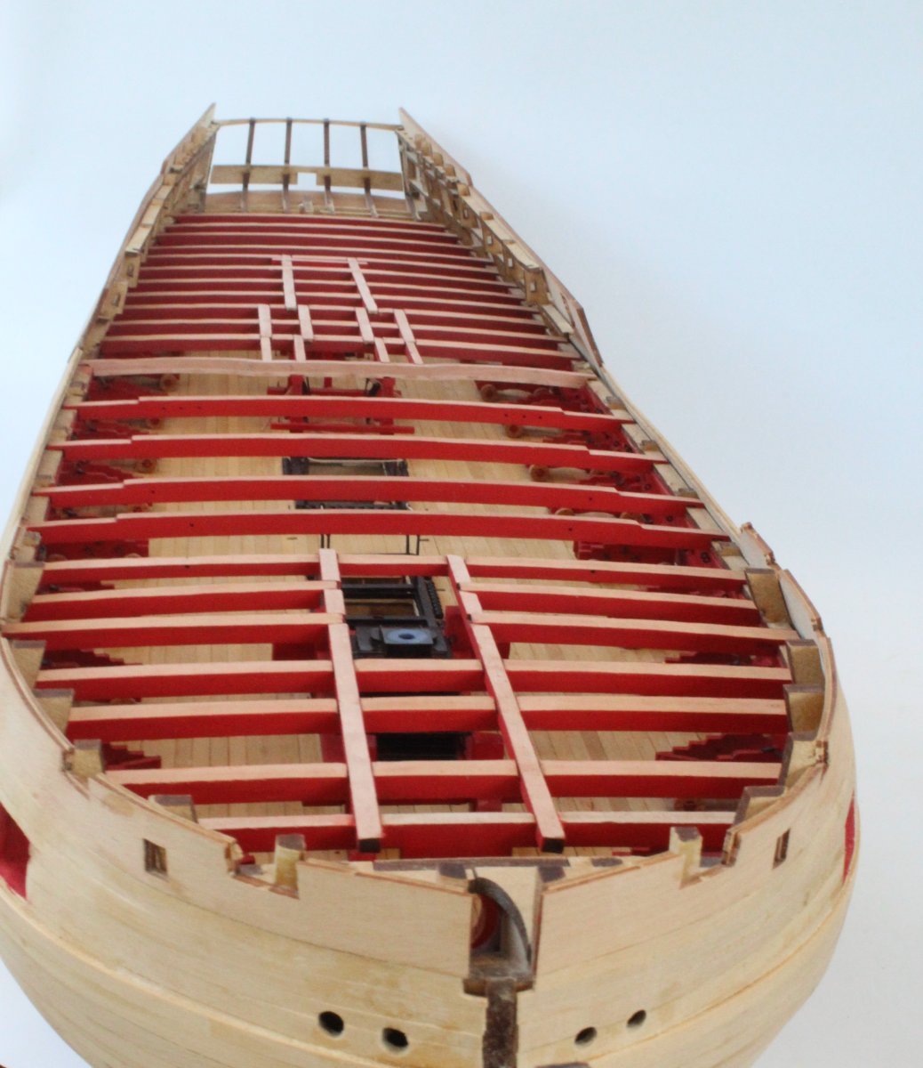
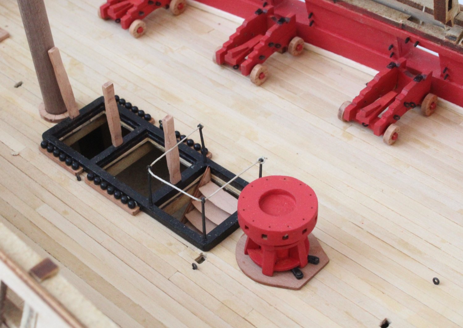
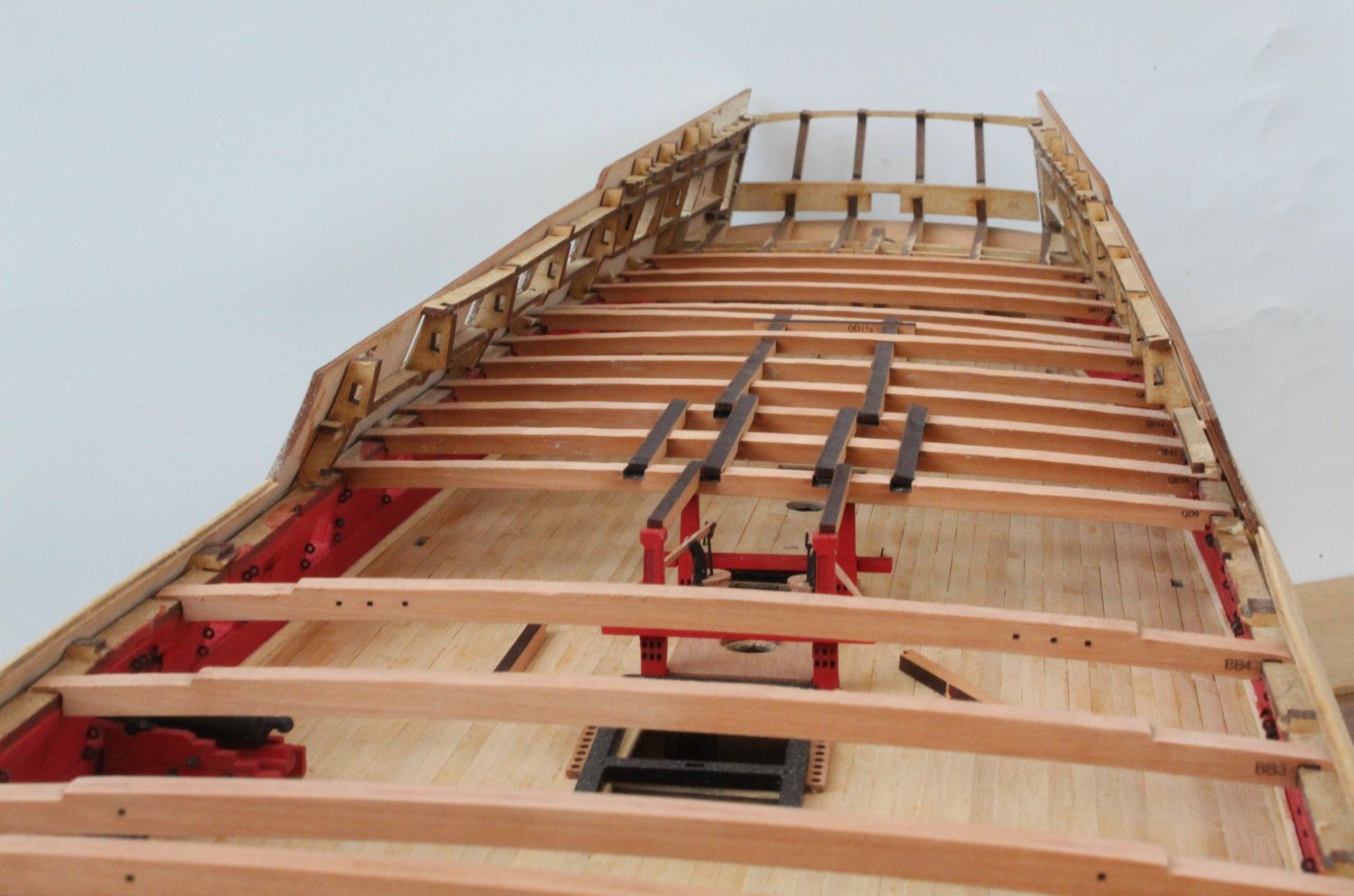
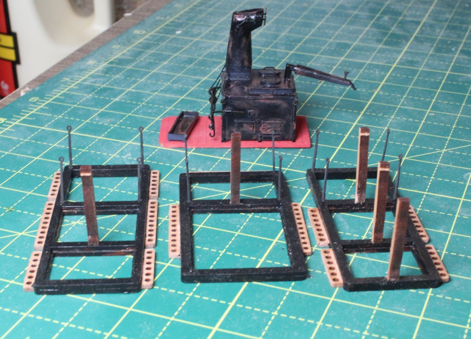
Quarterdeck Deck Beams, pillars, ships stove and lower capstan
A bit of a mixed bag sort of day with the build.
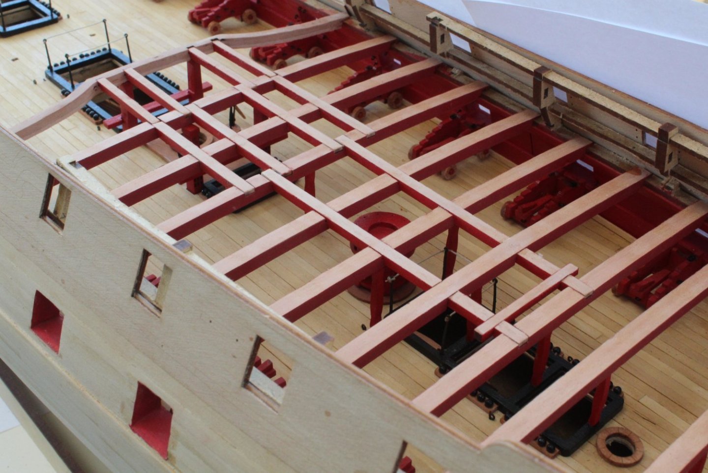
The first couple of hours this morning were spent cleaning the laser char from the quarterdeck deck beam beams and then test fitting. It was a tad tricky removing some bits of the MDF frame so the beams could be located. The beams outer edges also needed a bit of shaping.
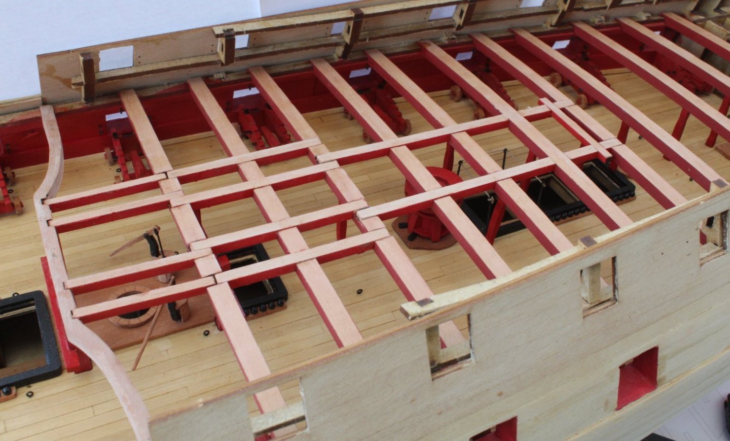
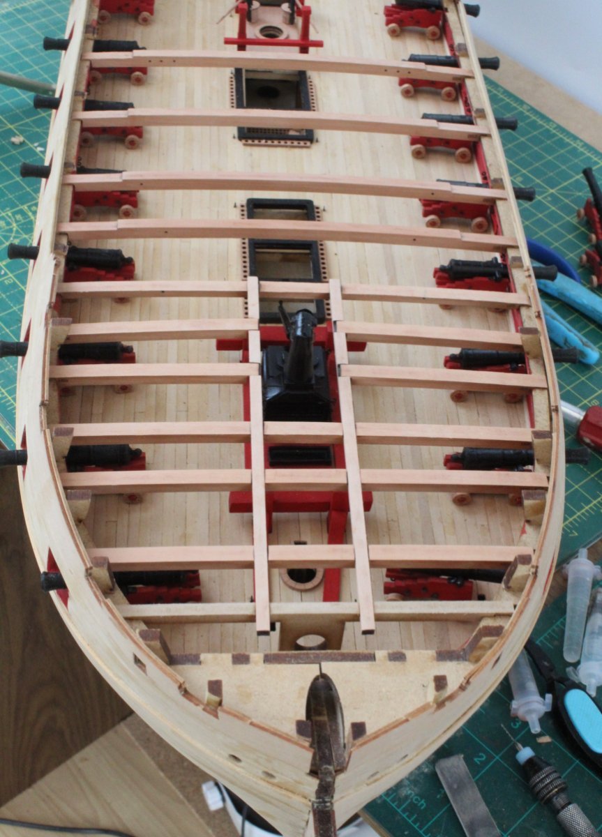
With all the standard quarterdeck deck beams in place (QD9 to QD19) I did a trial fit of the deck beam interlocking patterns. I am happy with how everything seems to fit. I still need to remove the laser char from the deck beam interlocking patterns before fitting. You may notice that a couple of the deck beams are not correctly seated in the photos below. There is build process required for the remaining quarterdeck deck beam (QD08) which still needs to be done.

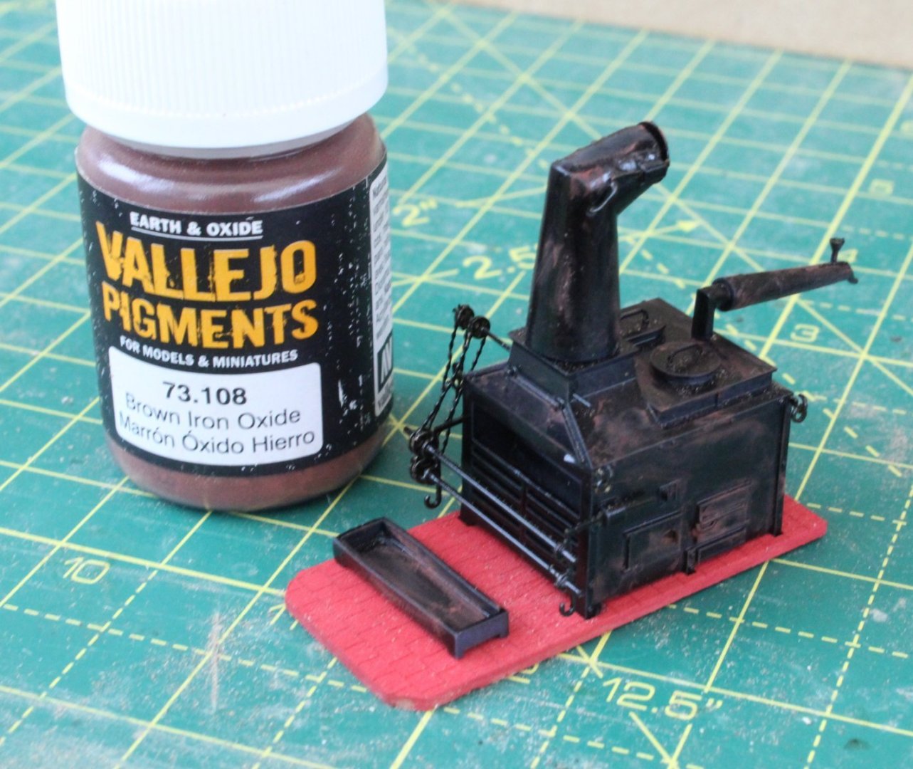
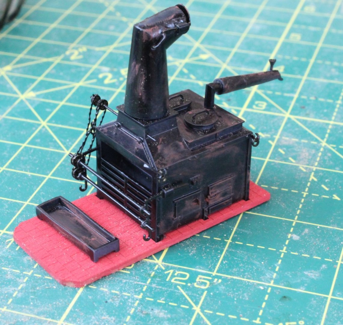
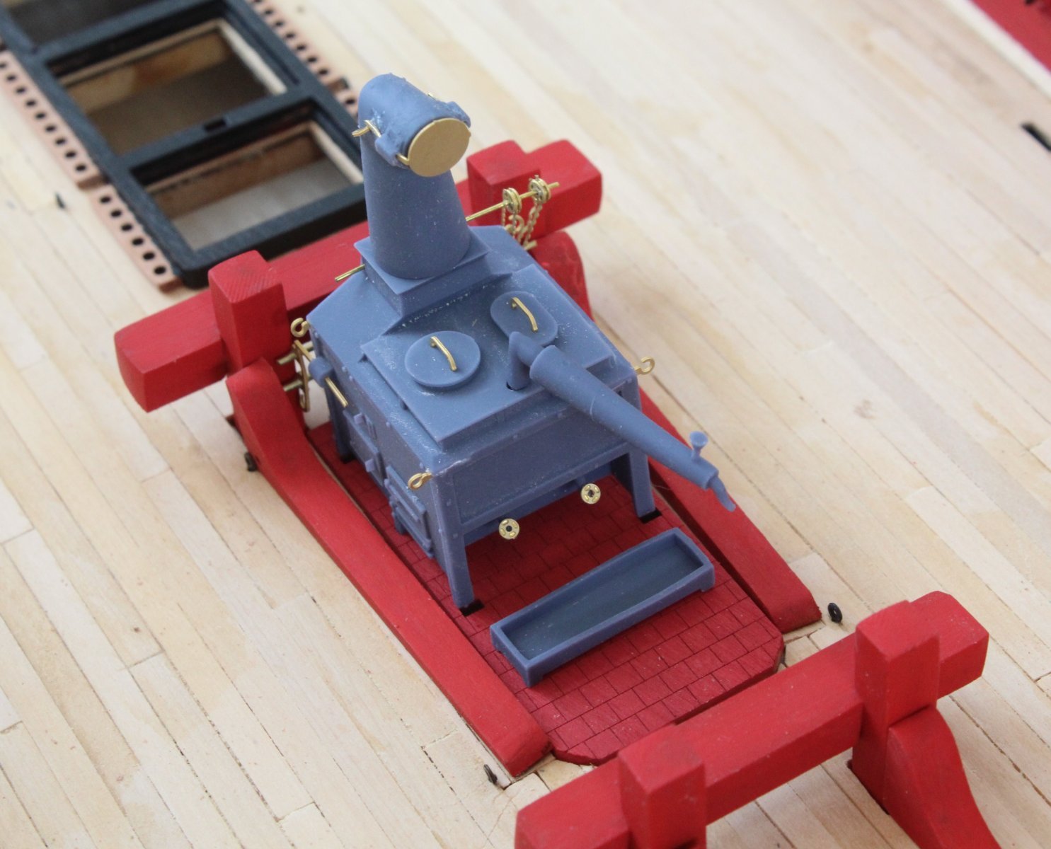
Next I decided to add some weathering to the ships stove using a brown iron oxide pigment. It looks a well used stove now.
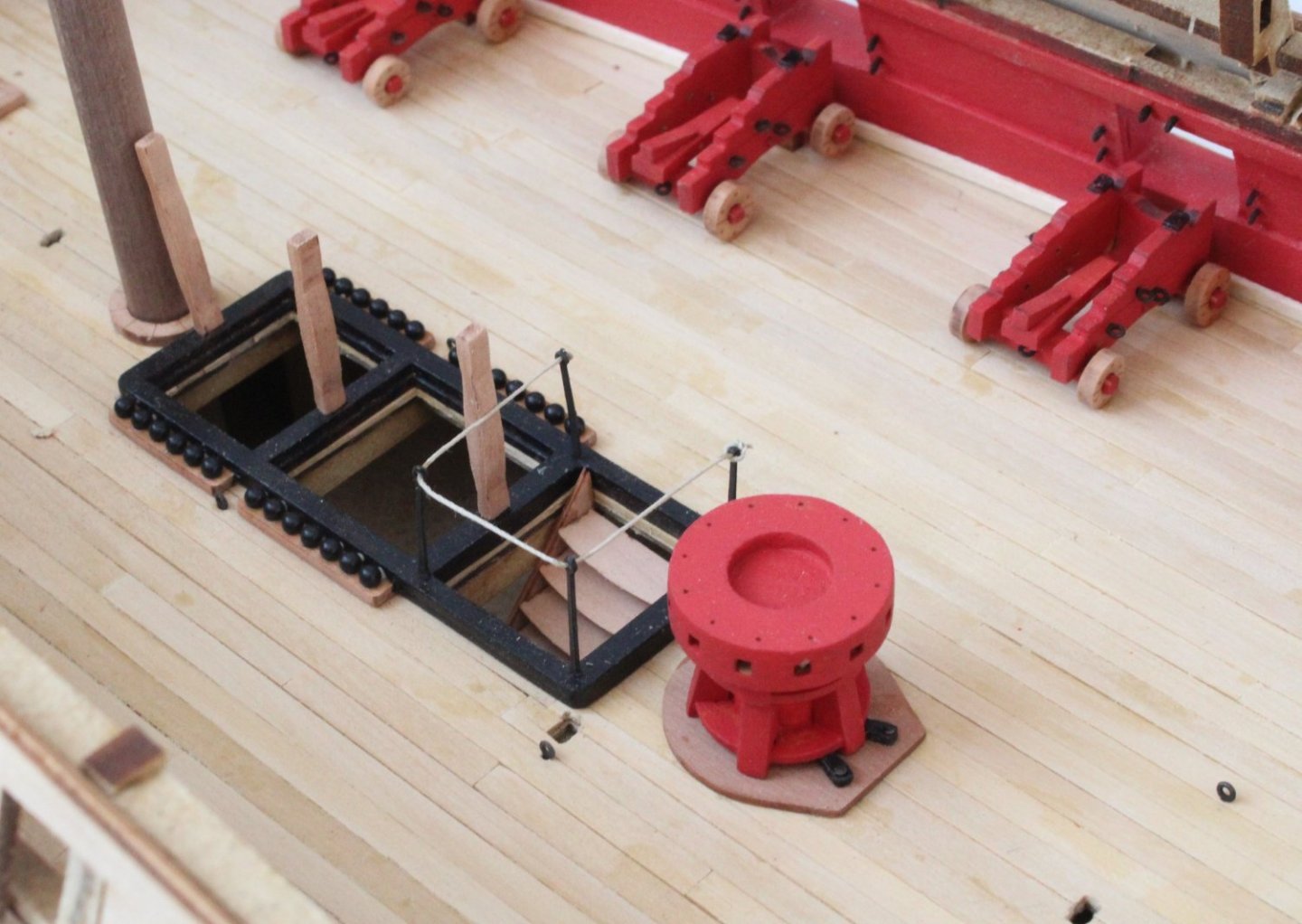
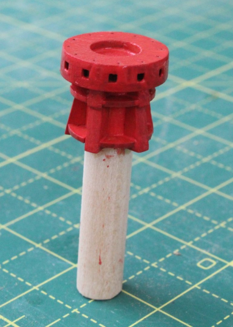
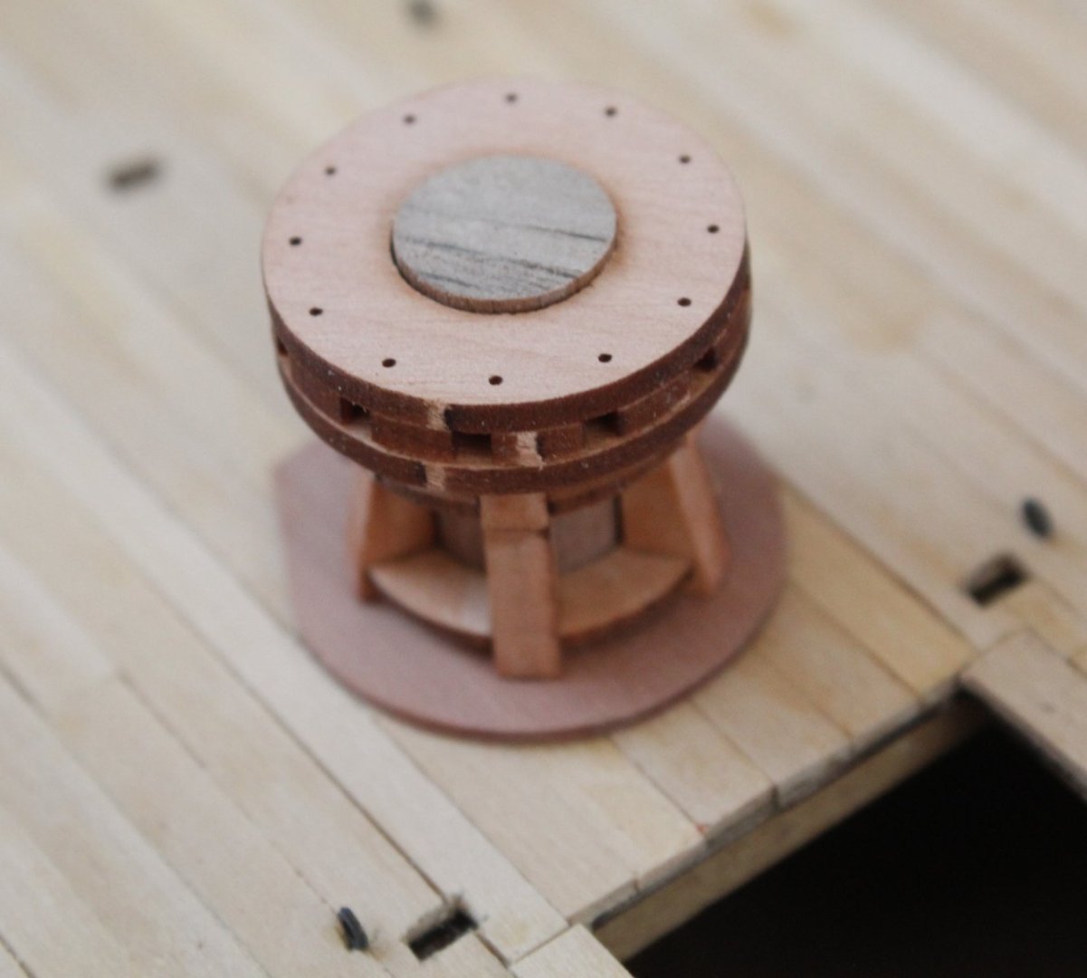
After applying a WOP to the lower capstan assembly it was given a coat of flat red paint. The paint is still drying in the following photo. I will apply a couple more coats before it ready to be fitted to the gundeck
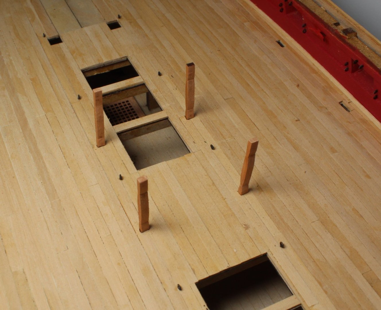
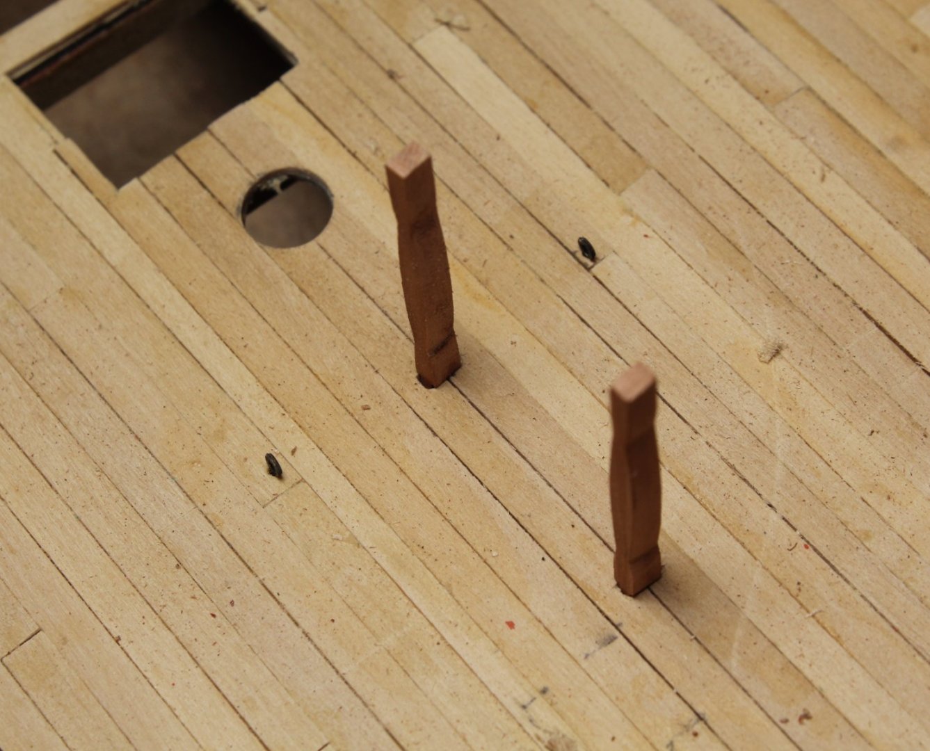
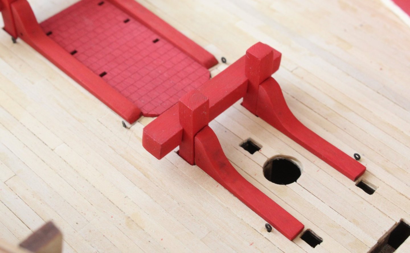
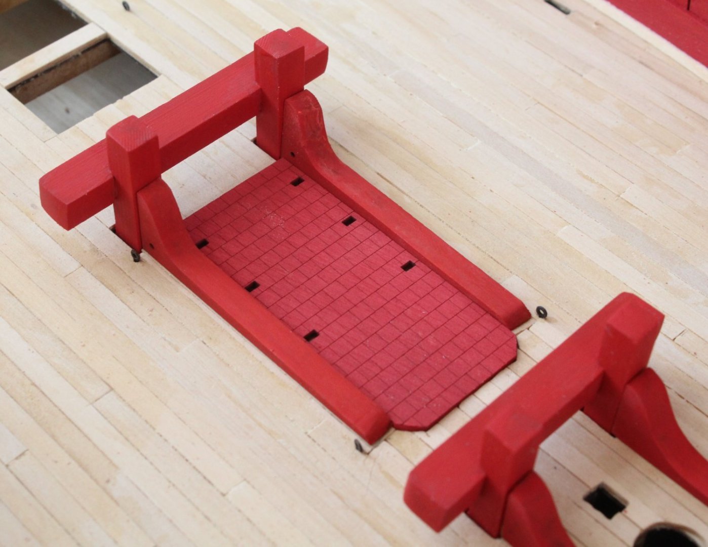
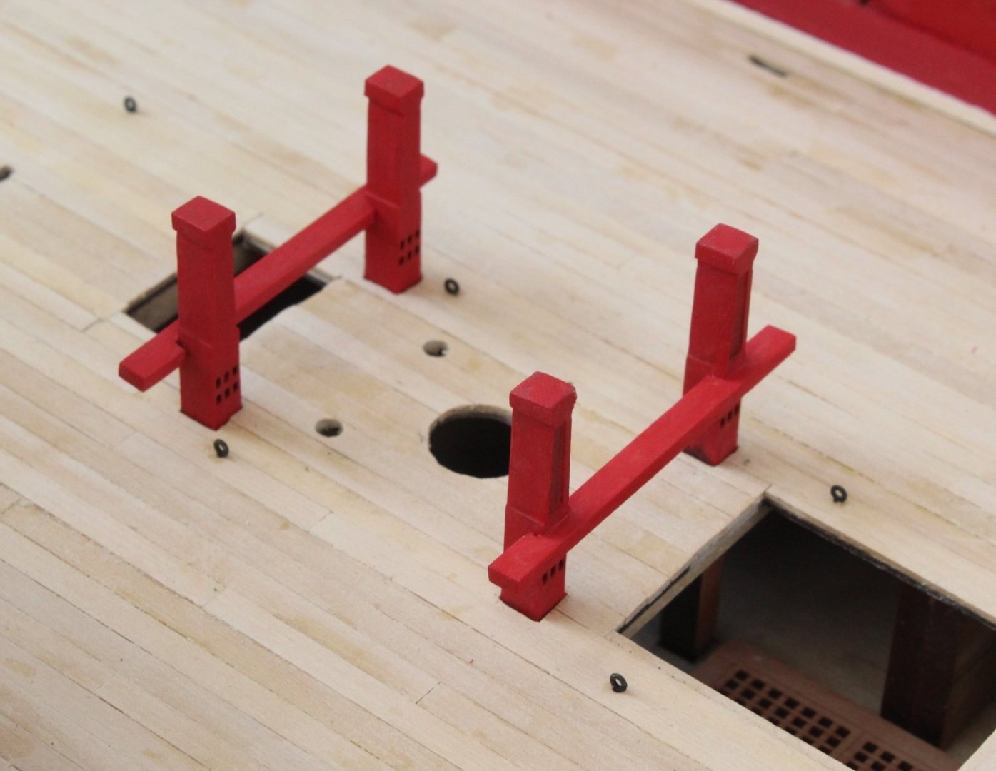
Next I test fitted the stanchions and deck pillars to the various hatches. I have always found it easier to check the fitting of these items prior fitting the hatches to the gundeck. The deck pillars may need to be trimmed so they will sit under the deck beams. They will be trimmed and fitted when it is time to add the various deck beams.
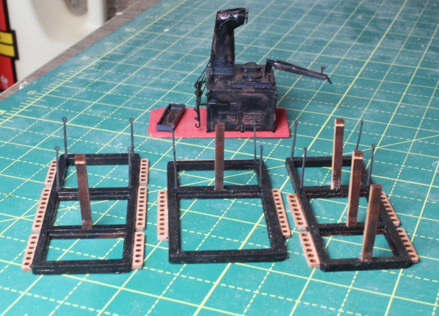
Finally I checked the fitting of gundeck pillars. Again these will be trimmed as necessary and fitted when the deck beams are added.
- Craigie65, Thukydides, Paul Le Wol and 7 others
-
10
-
Excellent workmanship Maurice.
- mtaylor, Blue Ensign and ECK
-
2
-
 1
1
-
Lower Capstan and Quarterdeck Beams
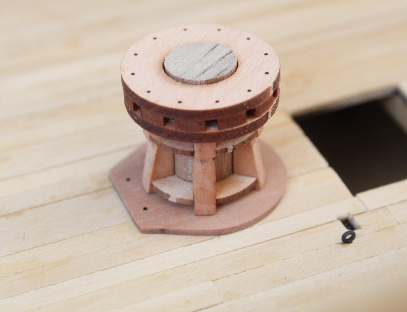
The replacement chokes for the lower capstan arrived this afternoon. It took no effort to build the capstan. Many thanks to @chris watton for his excellent help and support. Here is a couple of photos of the dry fit on the gun deck, prior to painting. The inner dowel will need to be trimmed a bit also.
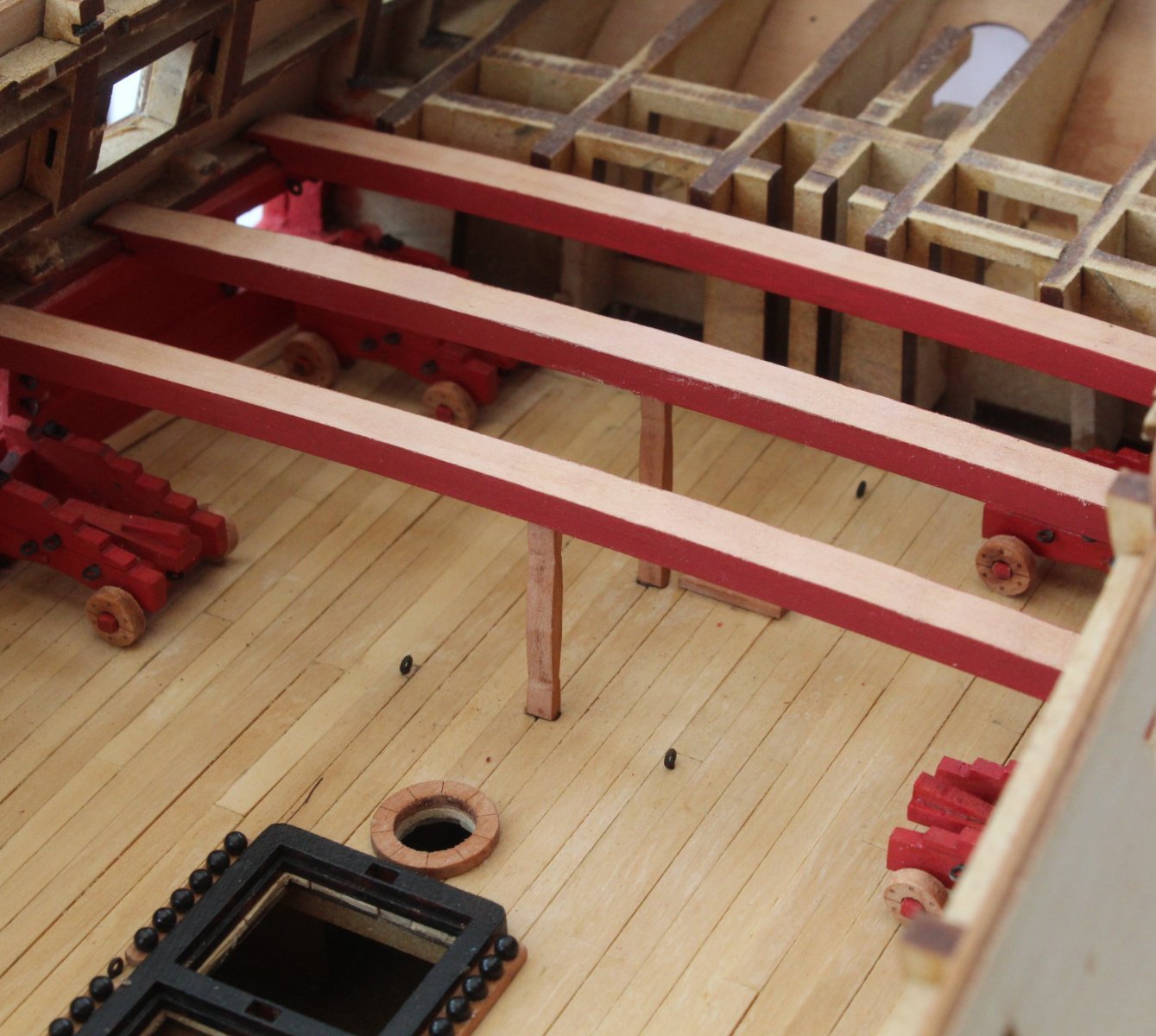
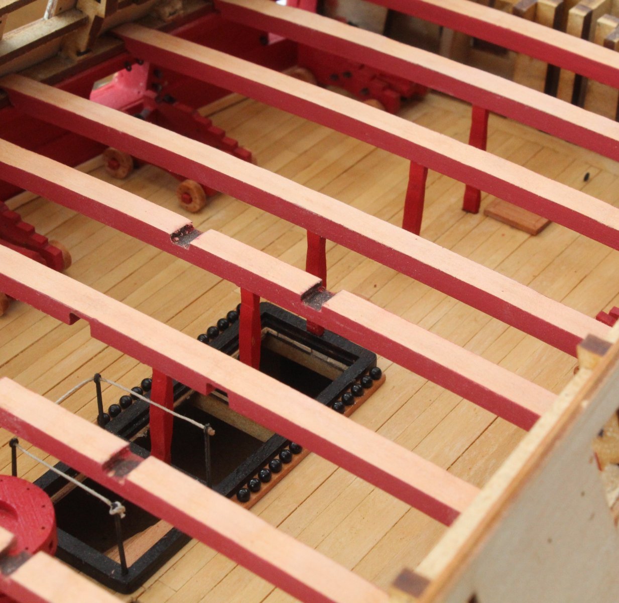
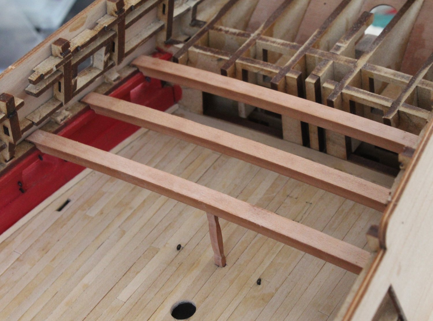
Progress on test fitting the quarterdeck deck beam is slow and steady. As can be seen below the deck pillars are checked to ensure they are the right height to ensure the deck is level.


-
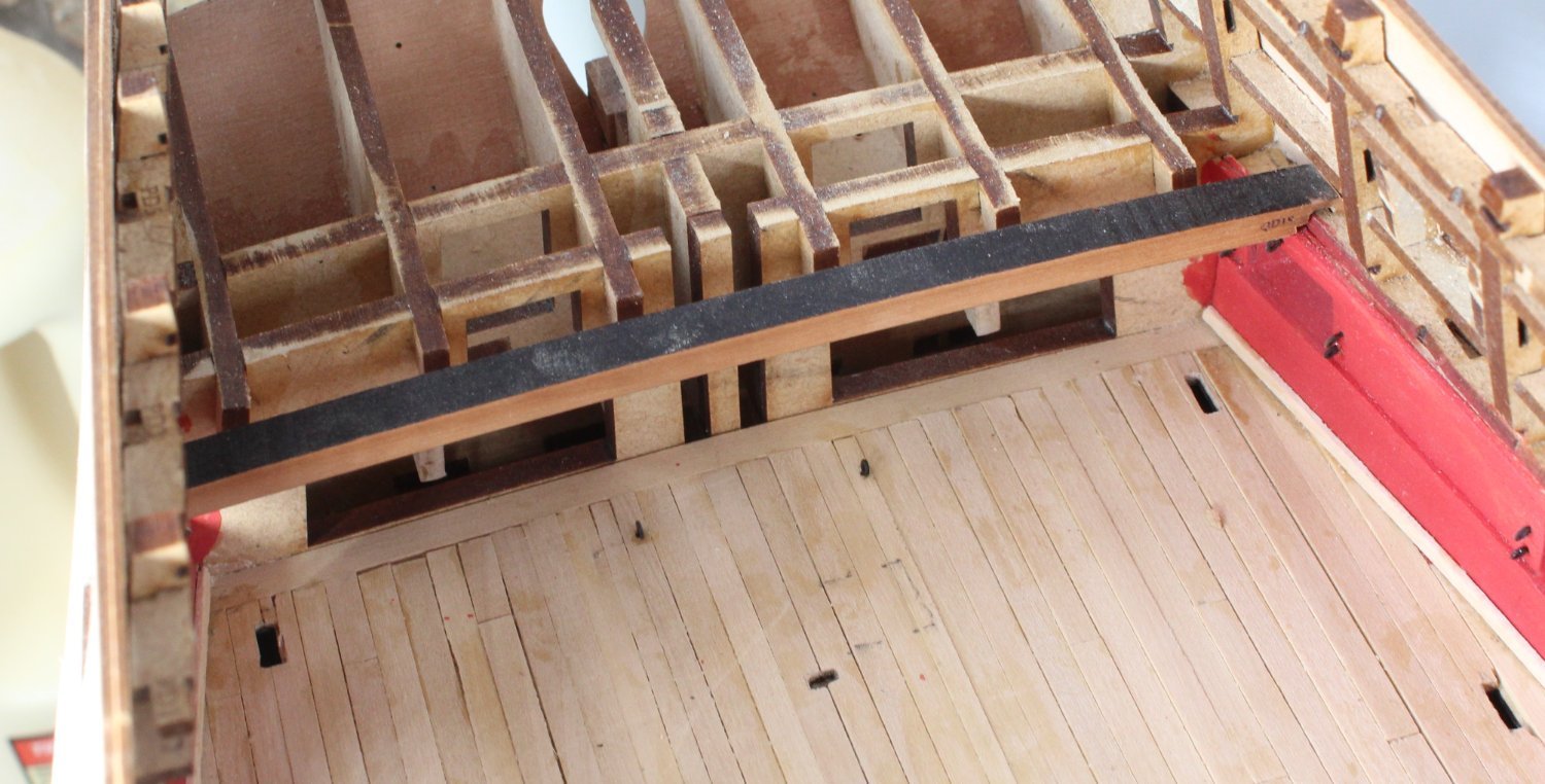
Deck Beams
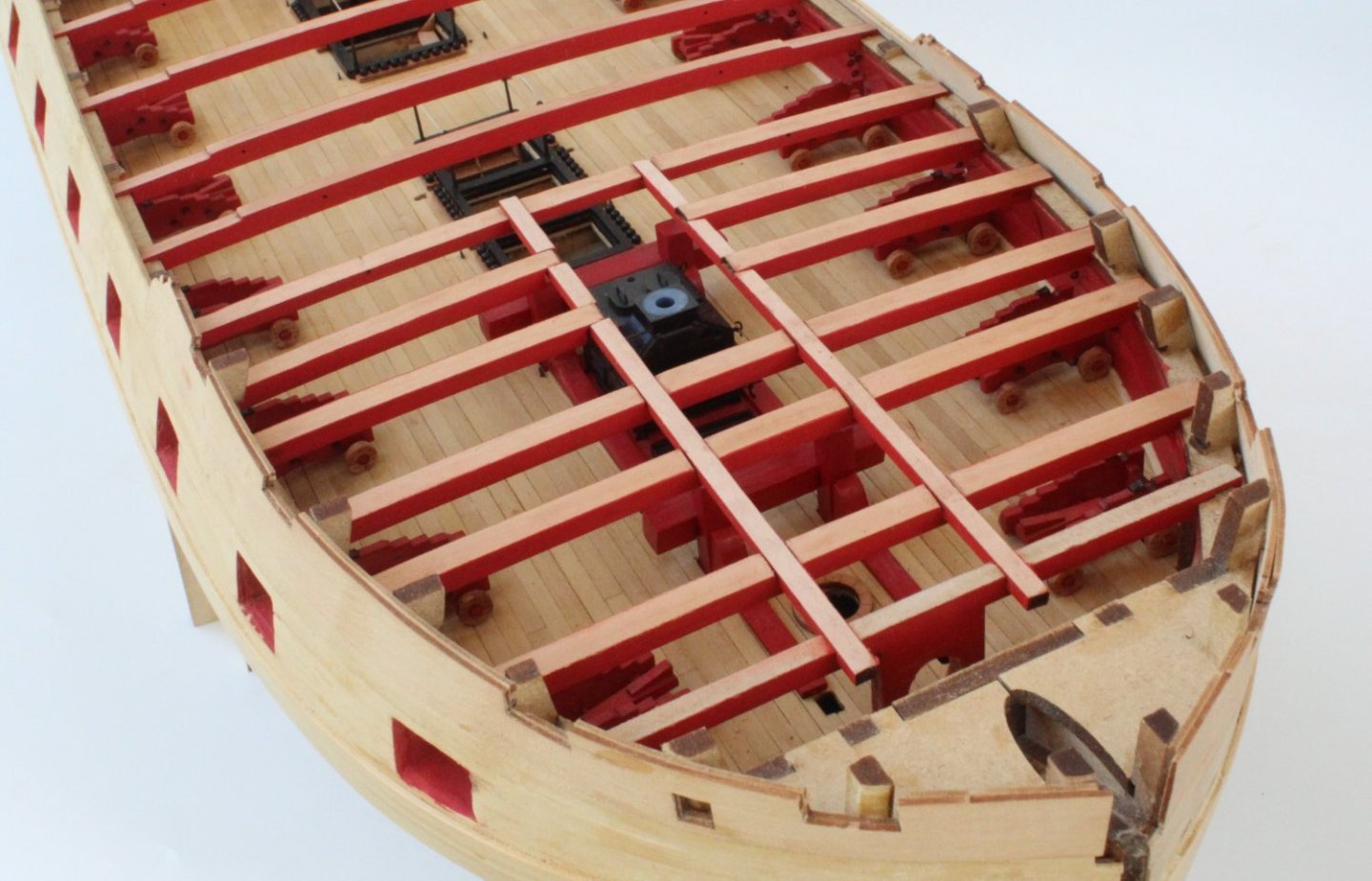
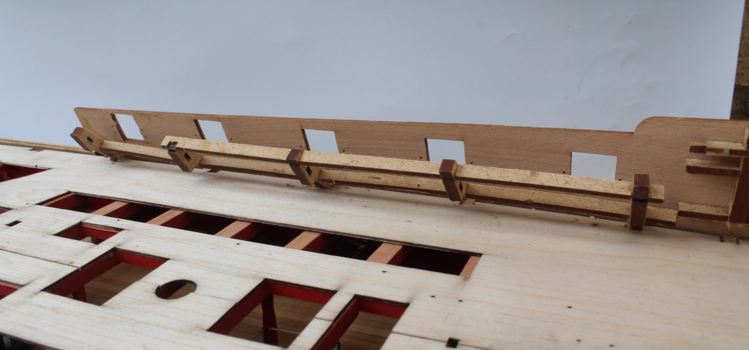
Whilst I wait for a couple of replacement capstan chokes to arrive I thought I would move on to cleaning up and test fitting the forecastle and quarterdeck deck beams.
Some of the forecastle deck beams outer edges required a little bit of shaping to match the bulwarks curve. I then used my rotary tool to remove the laser char from the deck beam top edges following by a fine sanding stick. The beams were then test fitted and everything looks good.


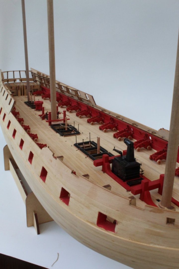
As can be seen below I have painted the ships stove black. I will add a little bit of weather before it is fitted,
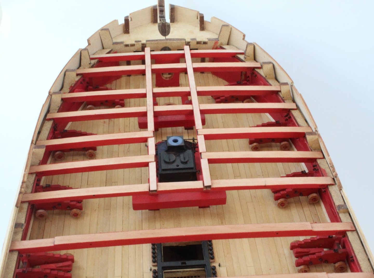
As I started to look at adding the quarterdeck deck beams there did not seem to be a way to get any of the beams to fit due to the MDF frames getting in the way. Thankfully there is a solution as the following note was included in the build manual with an example photo.
It is perfectly fine to selectively cut into and remove sections of the MDF frame so the beam can be manoeuvred into position.
Making a few careful cuts with my small hand held razor saw a small section of the first MDF frame was removed as can be seen in the photo below, as shown by the blue arrow

After a bit of work to shape the outer edges the first quarterdeck deck beam (QD19) was slotted in to place, noting the laser char still needs to be removed from the top edge.

- Kevin, chris watton, KentM and 6 others
-
9
-
-
-
Hand Pumps and Stove
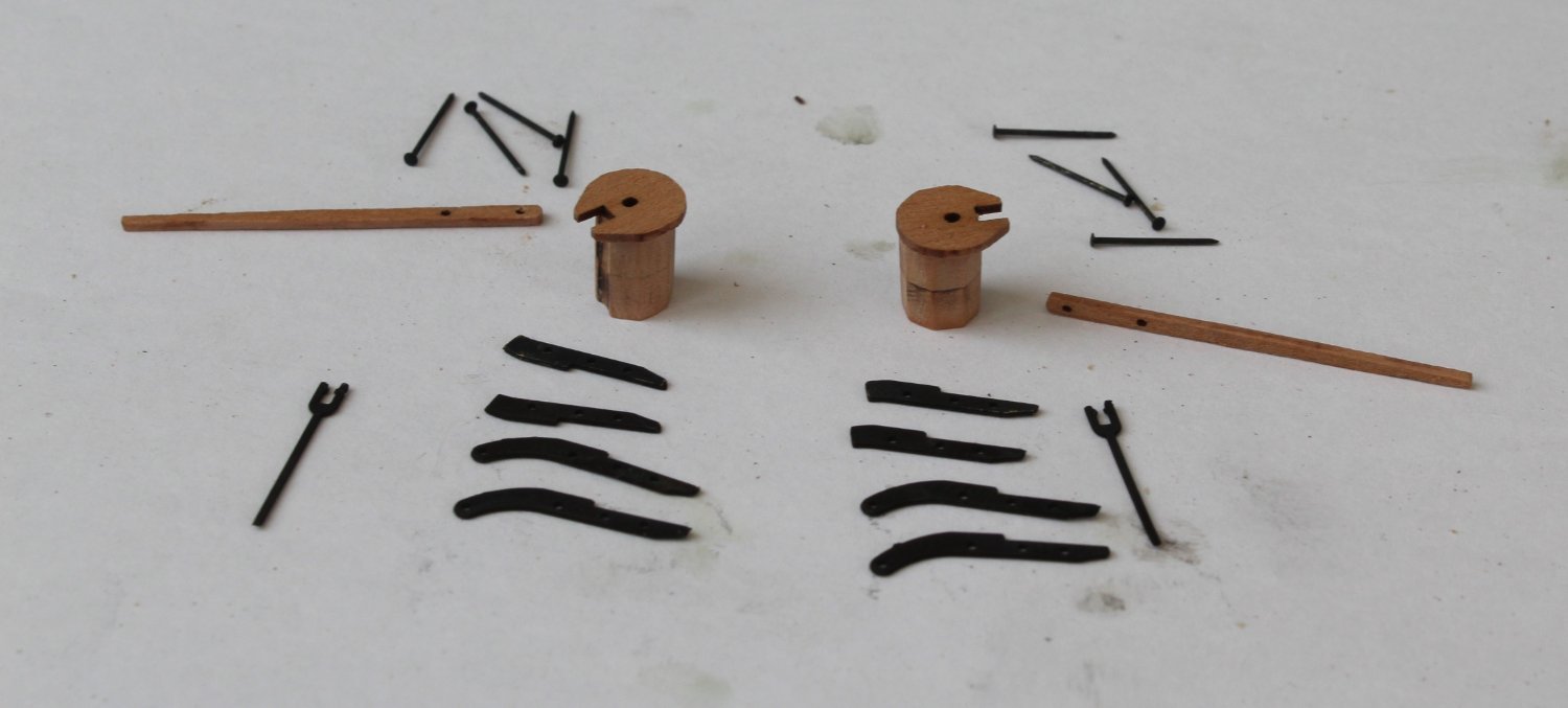
The final three gun deck items to build are the lower capstan, the two hand pumps and the ships stove.
I had a bit of a disaster with the lower capstan when I managed to break both chokes when I was adding the drumhead. It was my own stupid fault by applying to much pressure when attempting to get everything to line up. Hopefully there is a solution in the offering which may take a few days to sort out. As you can see below one choke in particular has seen much better days.

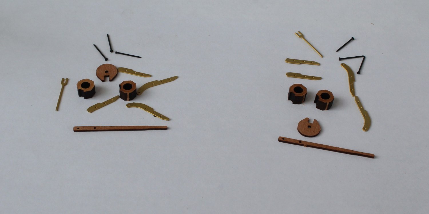
Moving on to the two hand pumps I thought I would detail my construction process in a bit more detail.
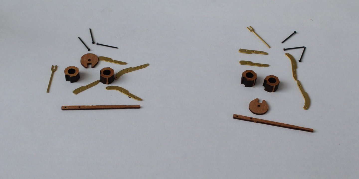
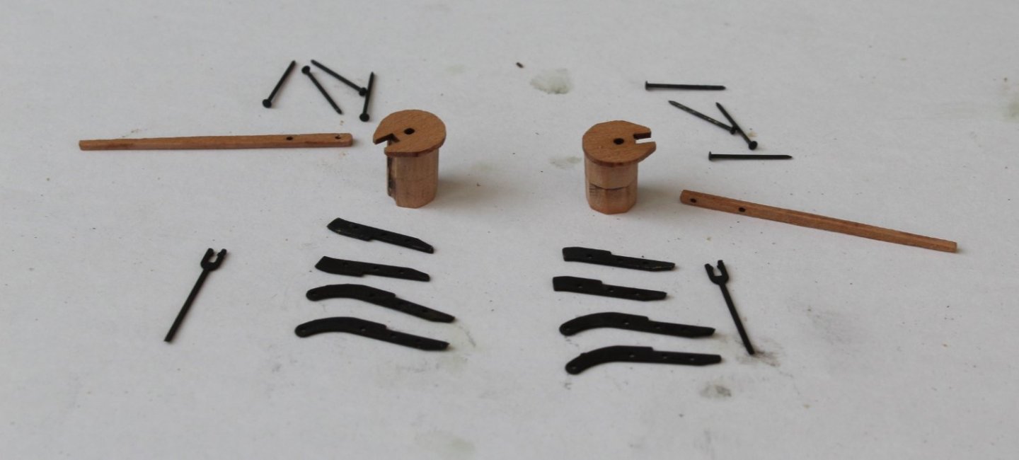
Step 1 - Assemble the raw materials
I have only shown three pins per hand pump in the photo below but 4 pins per hand pump are actually required.
Step 2 - Perform a basic dry fit of the various items
I am happy that everything looks good at this stage so I can move forward with the construction.

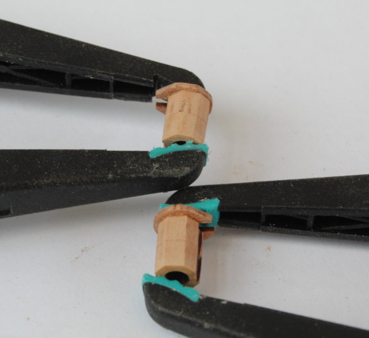
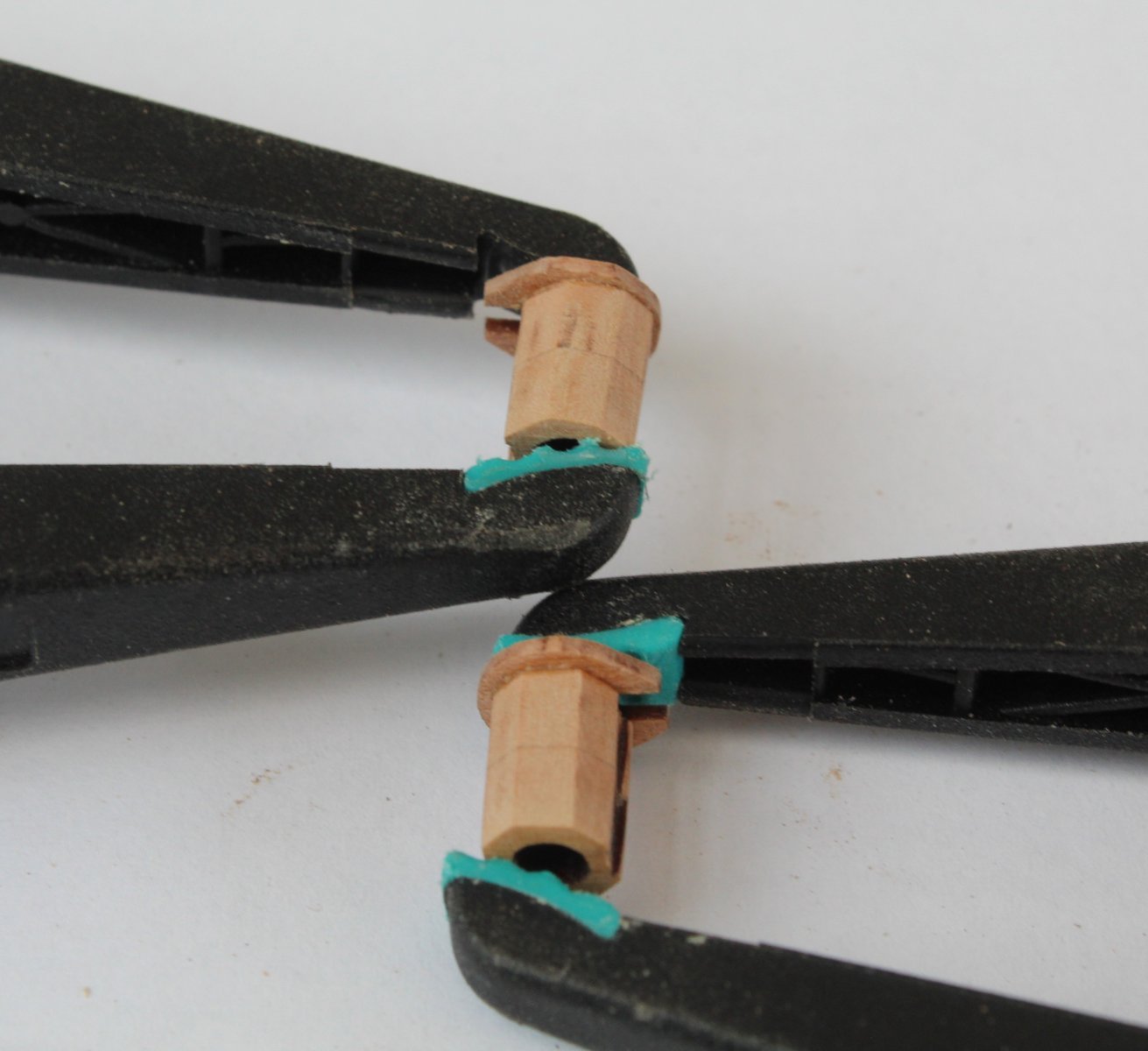
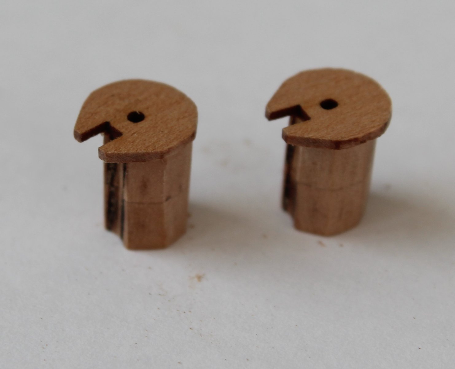
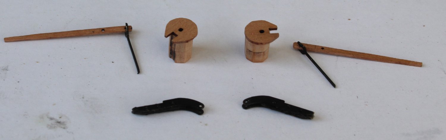
Step 3 - Glue the wooden parts together
It is important to remove the laser char from the visible edges, which I did before gluing the top cap in place.

Step 4 - Clean and Blacken the PE parts
The PE parts were soaked in acetone and then in hot soapy water a couple of times. The parts were then placed in a blackening solution. The assembly is now ready for the next task.
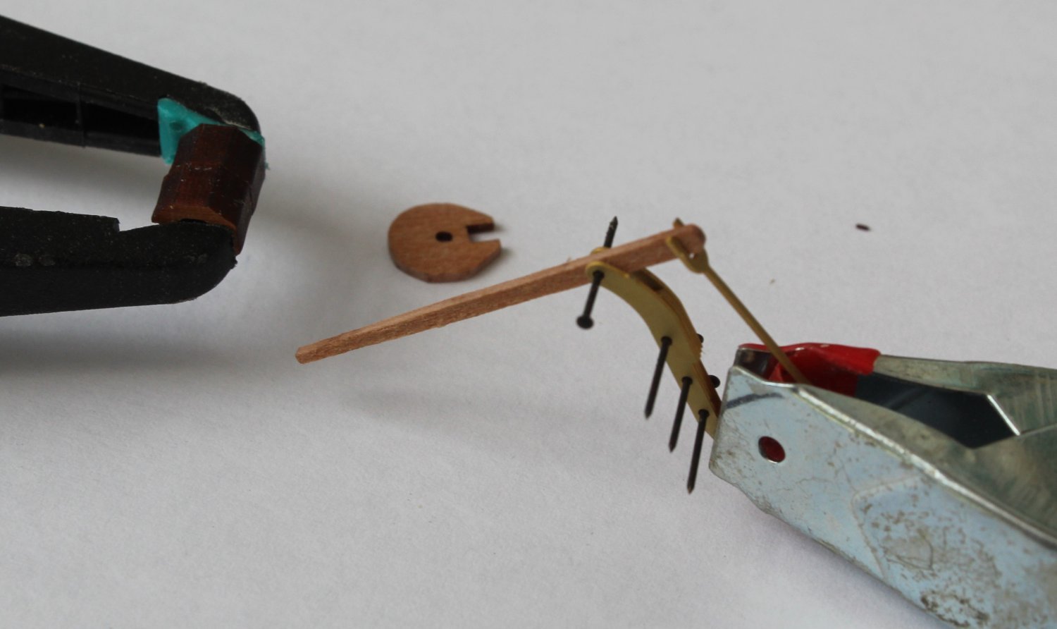
Step 5 - Assembly the pump handle
This was a two part task, the 4 main PE parts were glued together (ca glue) using 3 pins per assembly. It was then a simple job to add the handles to the pump body.

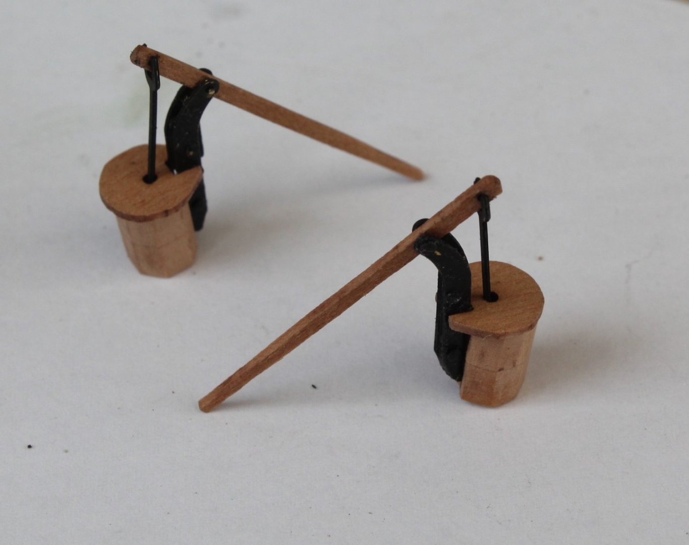
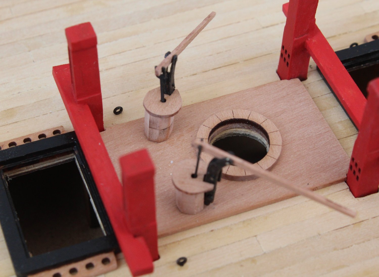
Step 6 - Dry fit the completed assembly on the gun deck
A length of dowel was added to the pump base, and the completed pumps were then positioned on the gun deck.
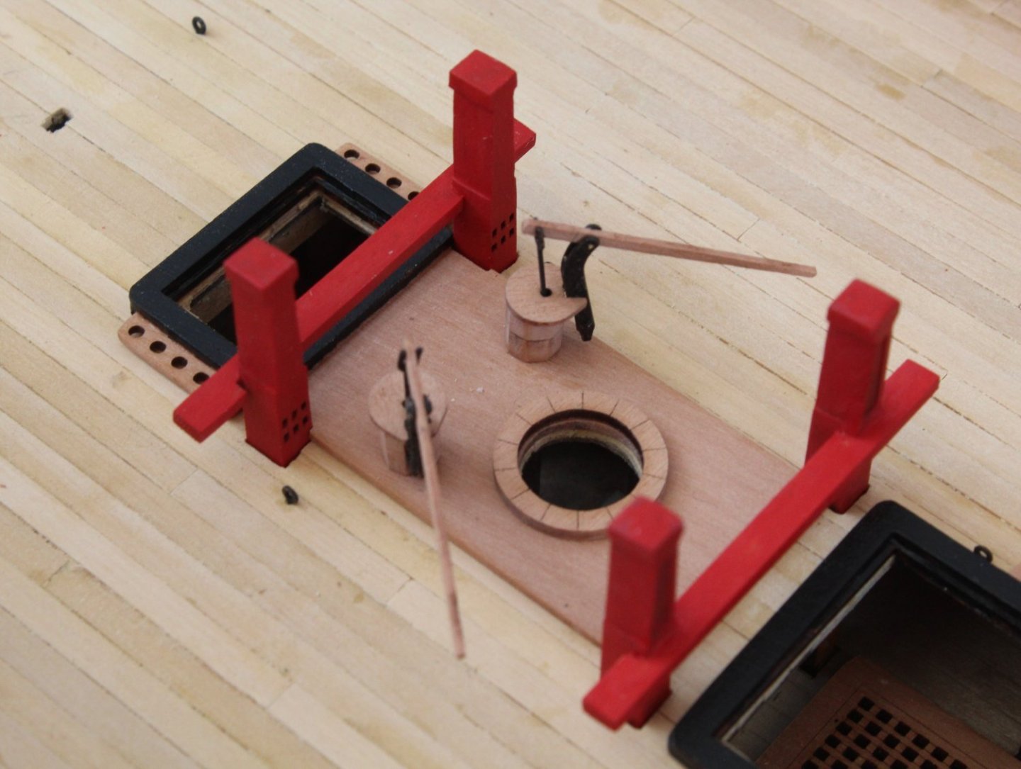

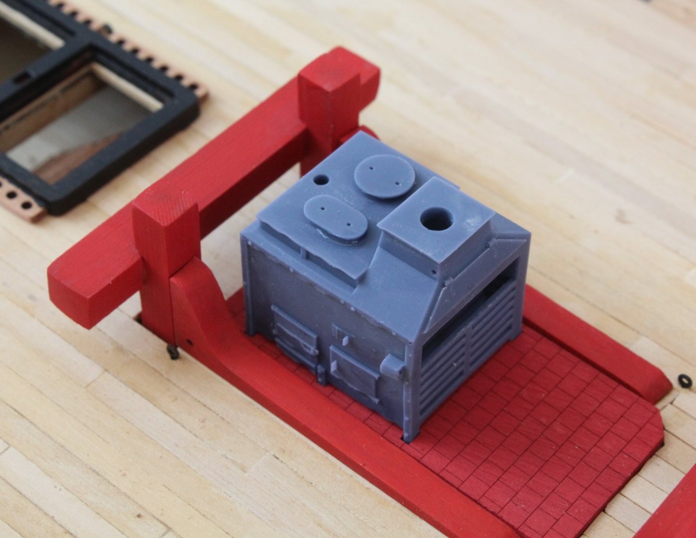
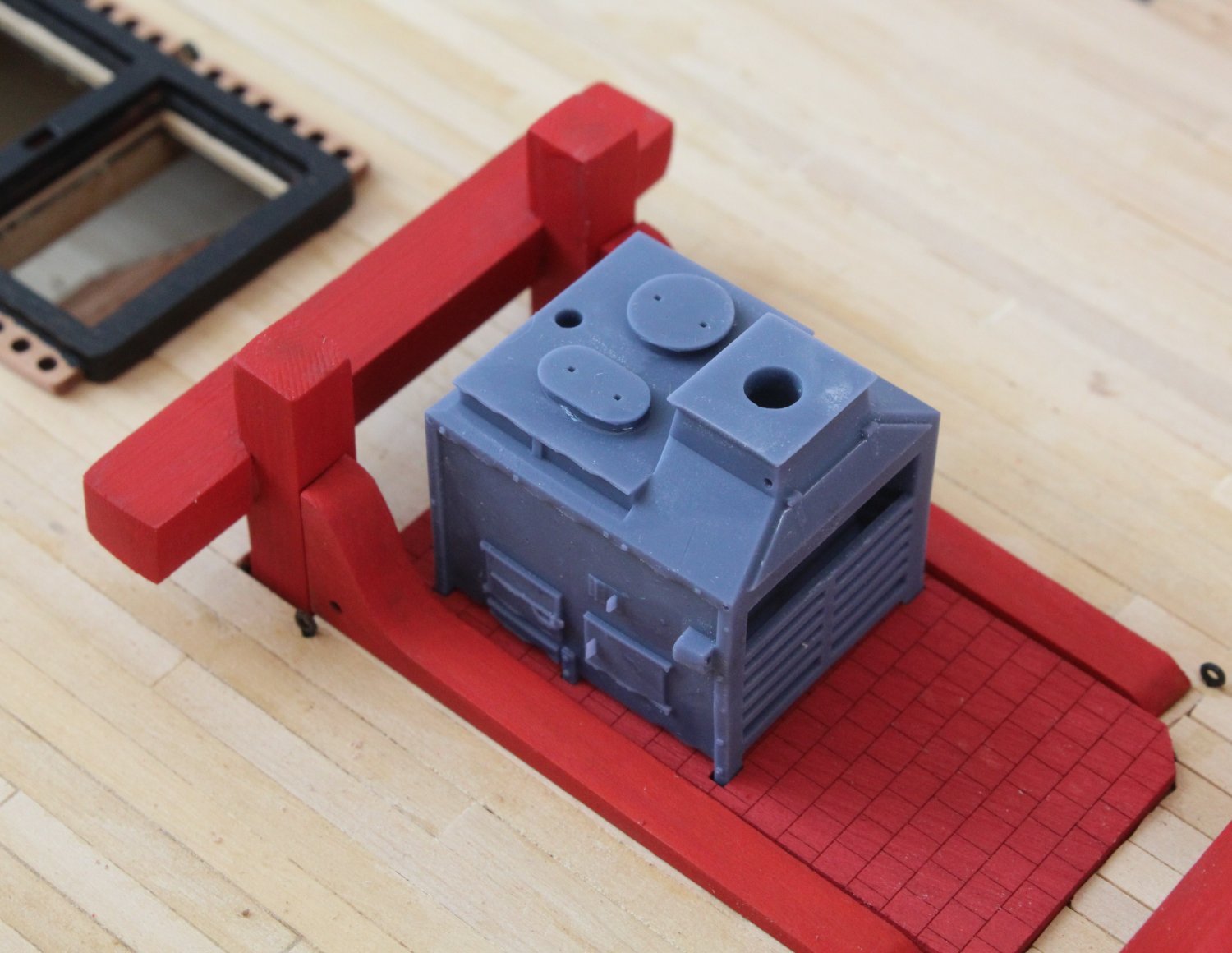
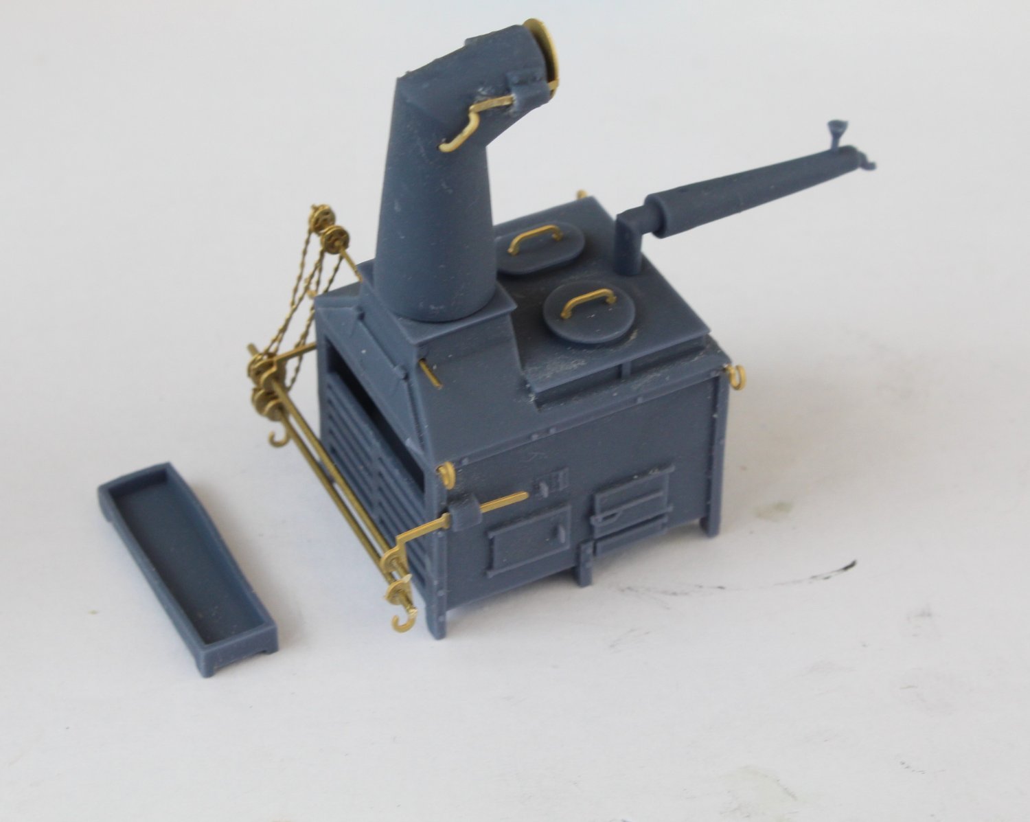
Moving on to the stove the basic stove body was dry fitted to the stove floor.
Next the various PE parts, after cleaning, were added to the stove. I did make a right mess of adding the two chains.
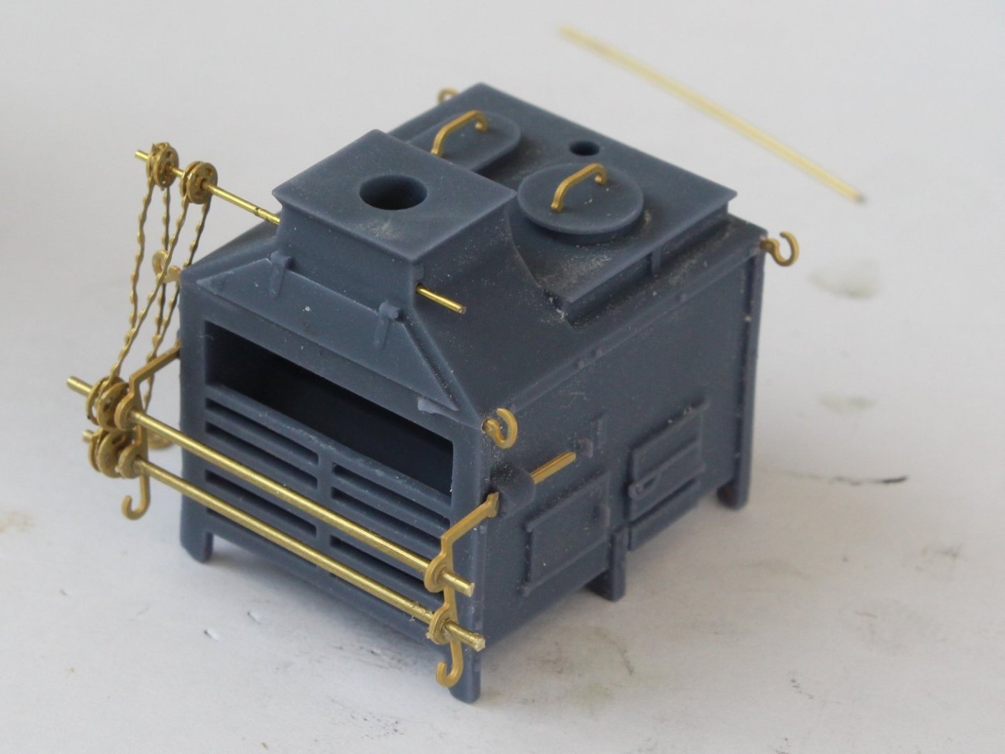
The other parts of the stove were then added.
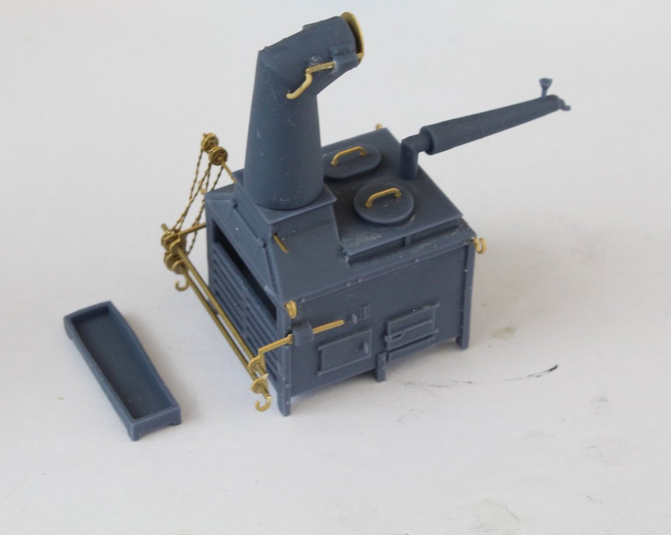
A quick dry fit of the assembly of the hull prior to the painting of the stove.

-
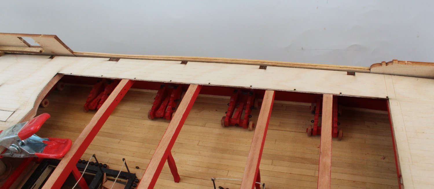
Looking good I see you've opted to cover the slots for the cannon tabs. I assume you are planning to trim the cannon front axle to remove the locating tab.
- Blue Ensign and mtaylor
-
1
-
1
-
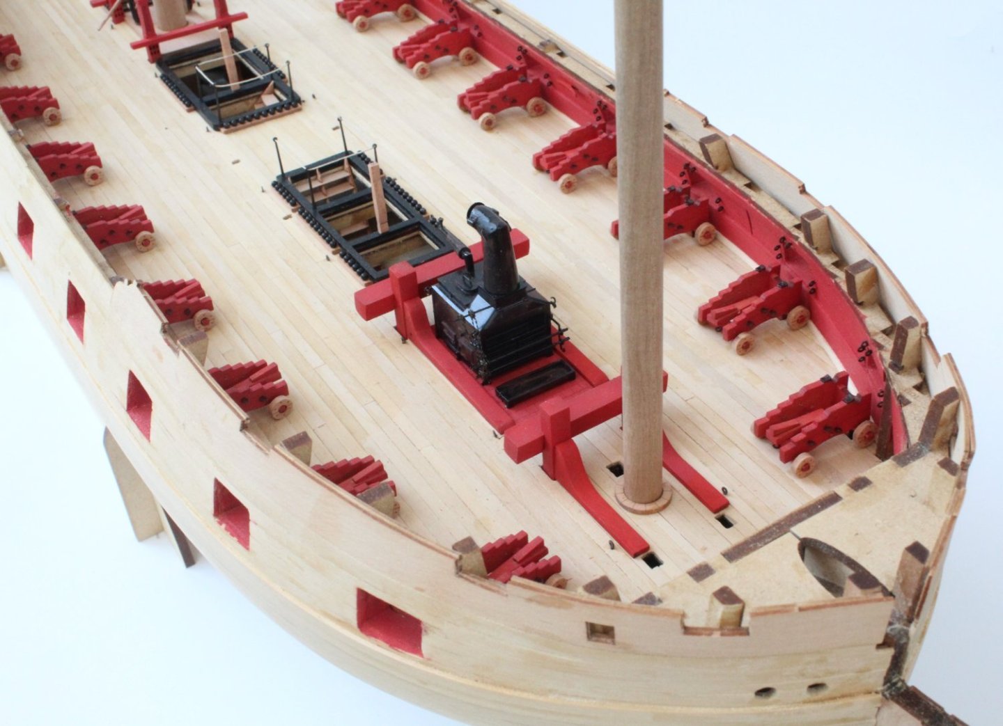
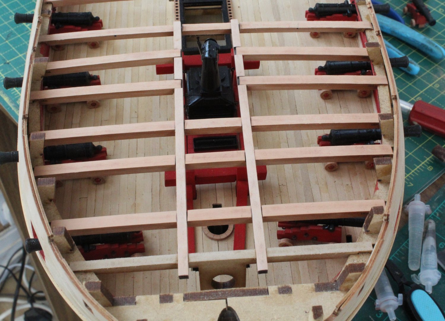
Gun Deck Items
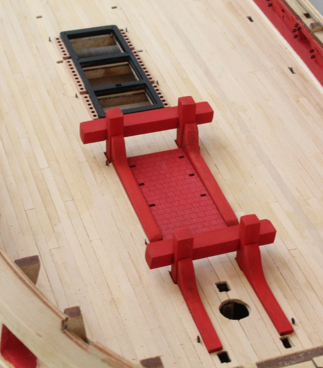
I was able to grab a couple of hours in the shipyard this morning. First task was to paint the various gun deck items. Flat red for the bitts, brick red for the stove base and dull black for the hatches. It was then a case of dry fitting the items to check everything looked good.
The first set of photos just shows the bitts and stove base
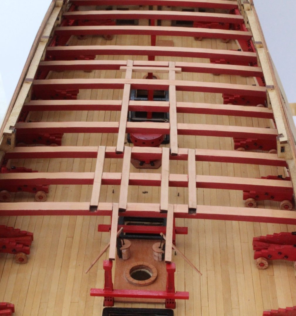
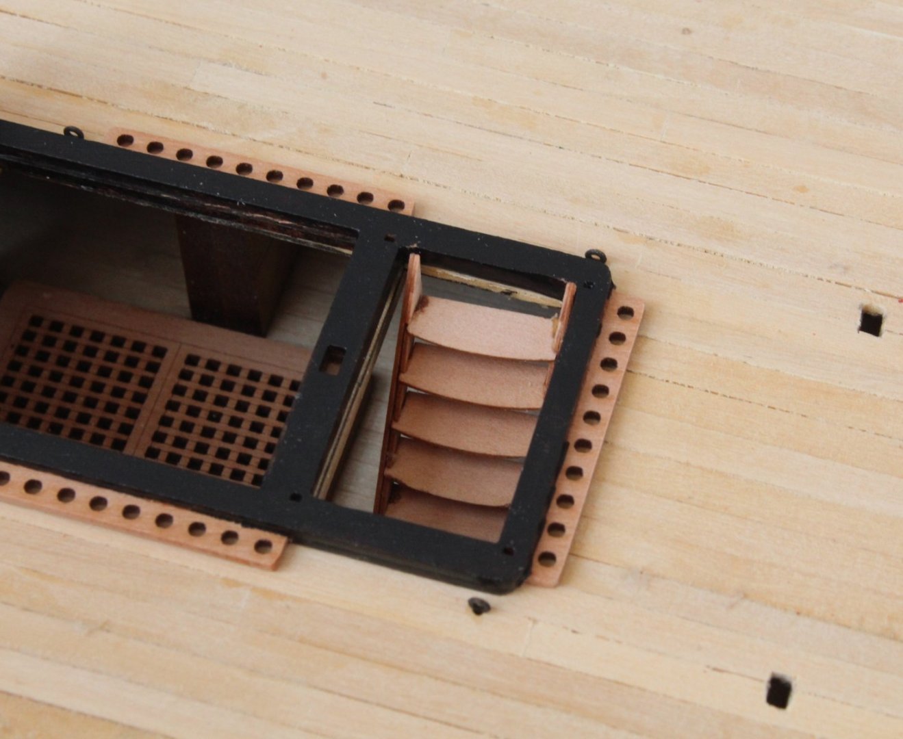
And now a set of photos with all the hatches dry fitted.

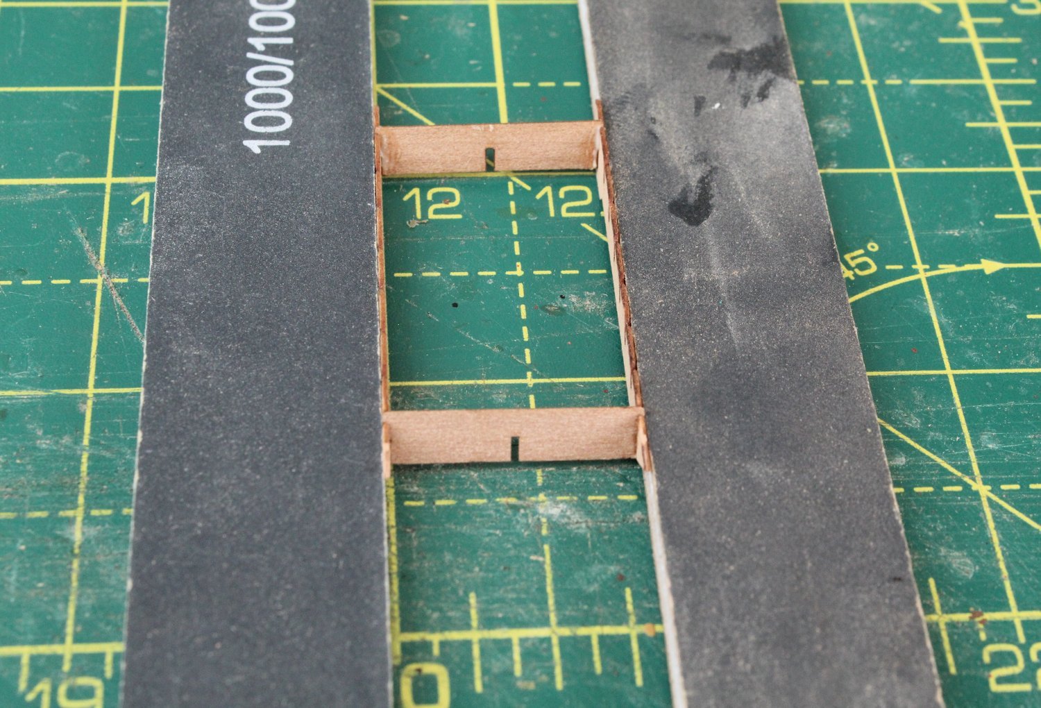
Next I moved on to building the 3 sets of ladders. I like to start with adding the top and bottom rungs and then leave time for the glue to cure before adding the remaining rungs. As can be seen I ensure the assembly is held square as the glue cures.

The ladders are now dry fitted, as shown in the next set of photos.


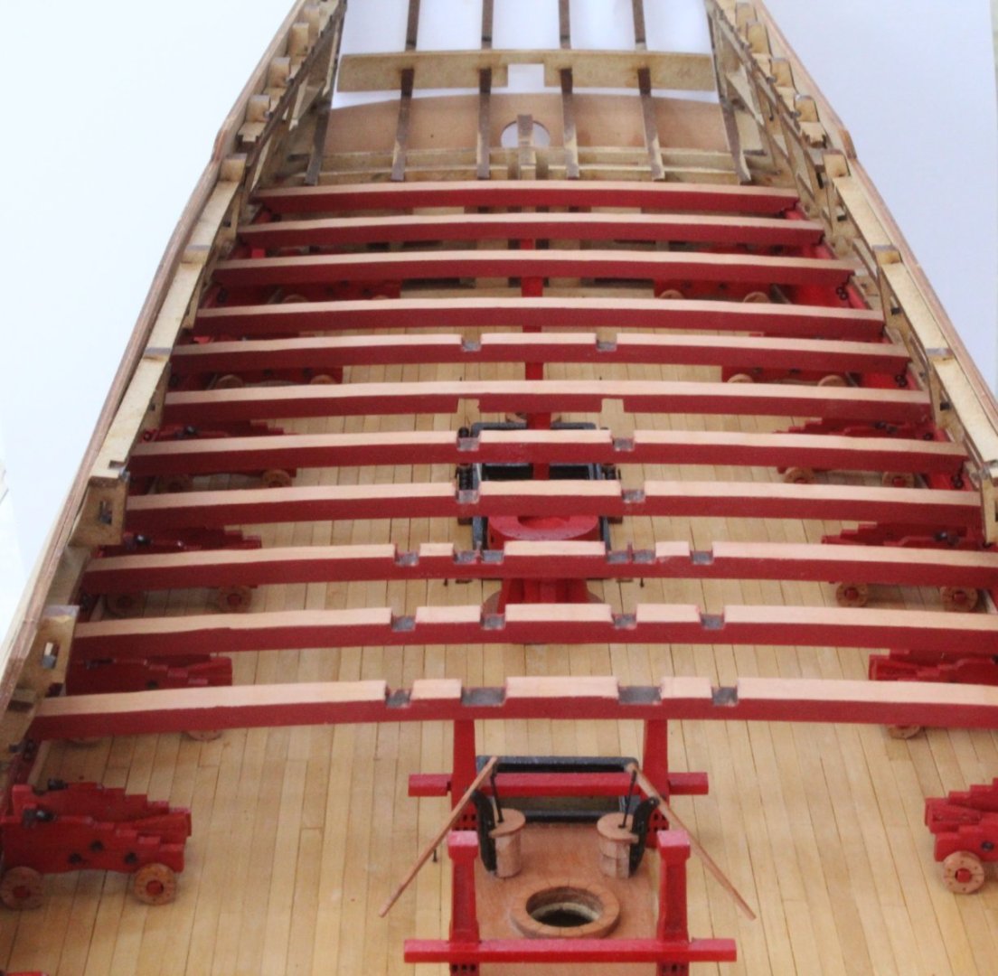
To complete this post I have included a photo of the gun deck with the completed items added. As noted in a previous post all the 24lb cannons have been built and test fitted.

Time to study the manual and plans before moving on to the next task in hand.
- Ryland Craze, chris watton, KentM and 7 others
-
9
-
 1
1
-
Starting To Add Gundeck Items
I was able to sneak a couple of hours in the shipyard today during our youngest grandson nap time. The first task I undertook was to remove the laser char from the various bitt parts. Once that was complete the bitt supports were placed in position on the gun deck but were not glued. The stove base pattern was also dry fitted. Some pva was added to the joints for the bitt cross beams which were then clamped in place.

After the glue had cured the clamps were removed and the assemblies were removed from the gun deck. The bitt assemblies were then refitted to check they could be fitted as complete assemblies. The bitt standards were also dry fitted.


Next the cannon ball holders on the various coaming assemblies were taped as they will not be painted black.

The various assemblies were then coated with a WOP and will now be left overnight to dry in readiness for painting. I am hoping I can sneak some time in the shipyard tomorrow after the weekly grocery shopping trip and before the arrival of our two eldest grandsons (10 and 12) after lunch.
- chris watton, KentM and Morten
-
3
-
13 minutes ago, Thukydides said:
You could try filling the gap with milliput or greenstuff. You would need to paint the cannon after doing so, but looking at that gap it shouldn't be hard to fix with a bit of putty.
@chris watton is sending me a replacement which is greatly appreciated.
- Ryland Craze, ECK, Thukydides and 3 others
-
6


HMS Indefatigable 1794 by Glenn-UK - Vanguard Models - 1:64
in - Kit build logs for subjects built from 1751 - 1800
Posted
Thanks, I have already started to make a simple jig to help with the alignment and fitting, using the top shelf as a guide