


Glenn-UK
-
Posts
2,633 -
Joined
-
Last visited
Content Type
Profiles
Forums
Gallery
Events
Posts posted by Glenn-UK
-
-
Foremast Wolding
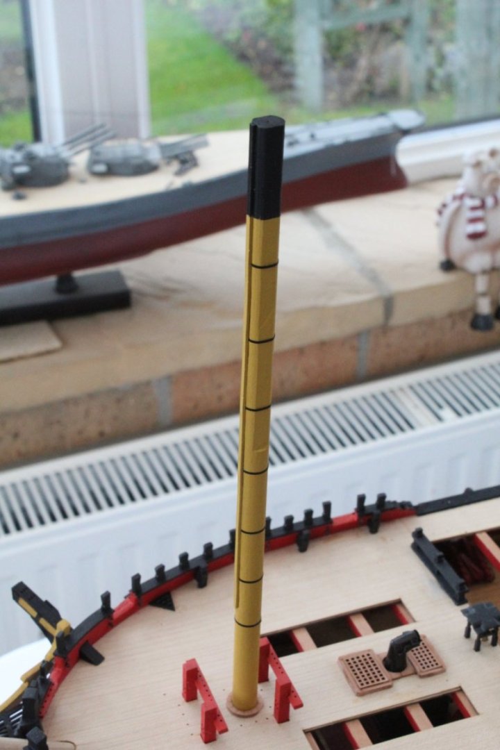
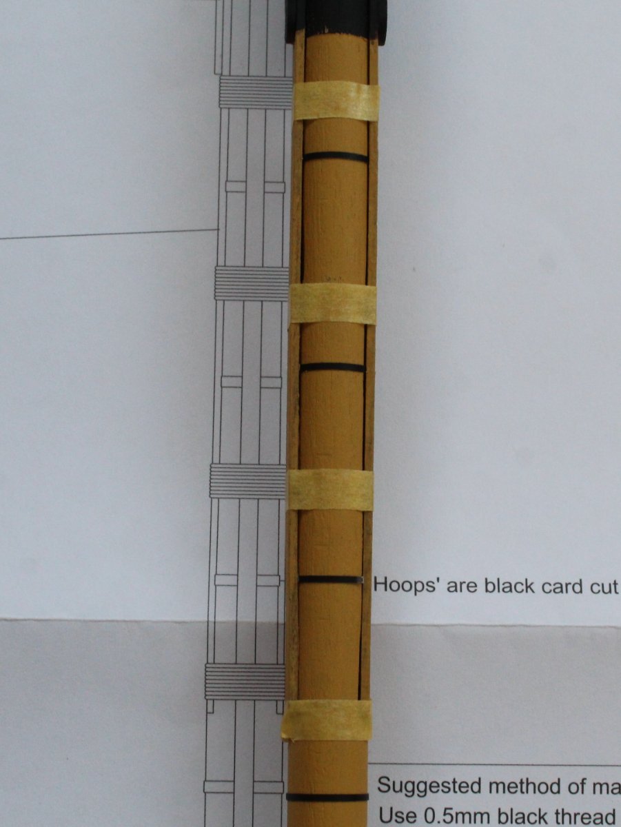
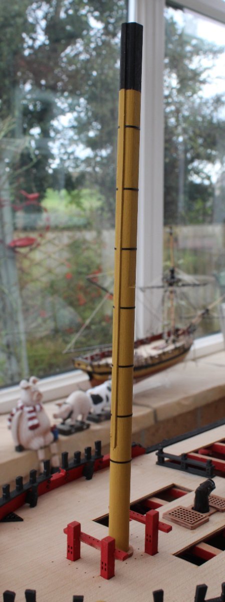
I thought I would share my method for adding the wolding to the foremast. With reference to the plan sheet I did add some tape to indicate the lower edge of each wolding. The upper tapes are in the correct position, but they look wrong in the following photo due to the angle used to take the photo.
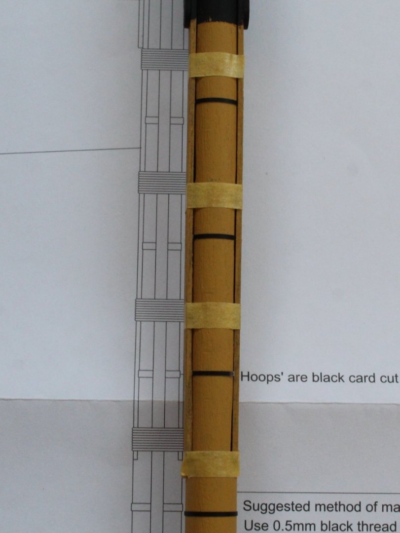
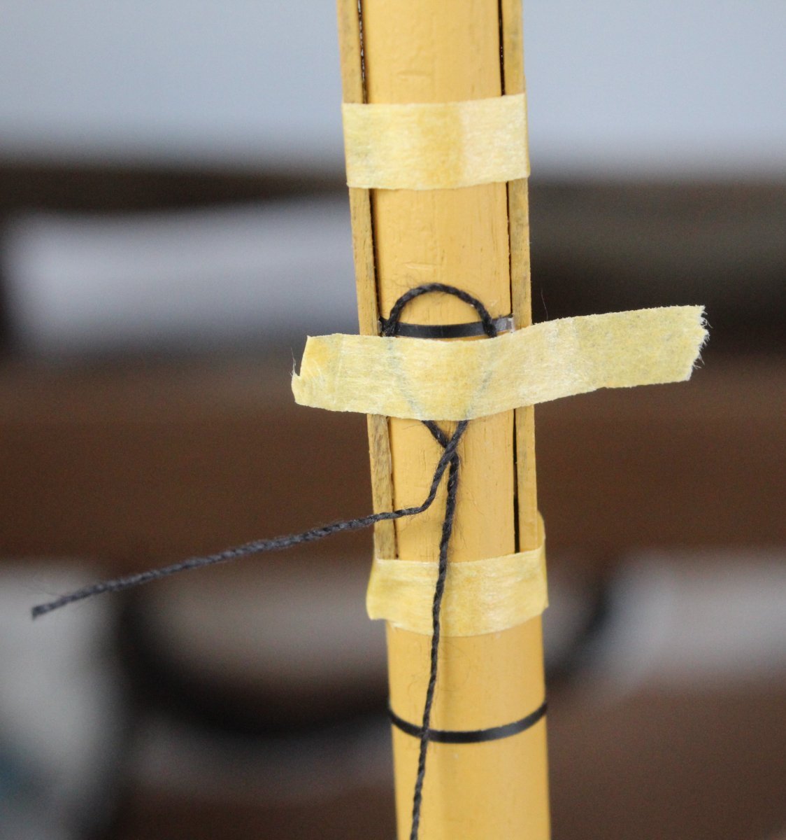
I cut a 500mm length of 0.5mm black thread and made a small loop in end which I then taped to the mast.

It was then a simple case to add the wolding, by wrapping the thread around the mast 10 times. The tape securing the loop end was then removed so the thread could be passed through.
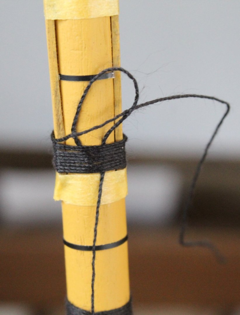
The bottom end of the thread was then gently pulled down to trap the other end in the loop. The wolding was then adjusted as necessary and the excess material trimmed.
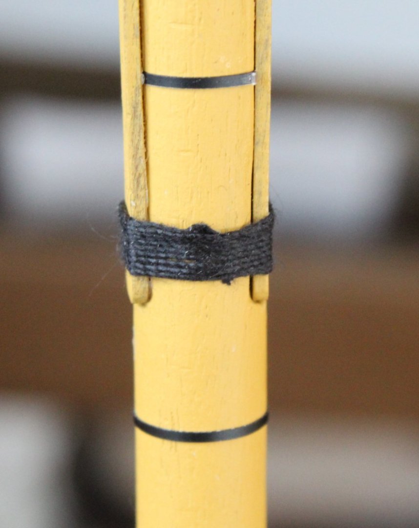
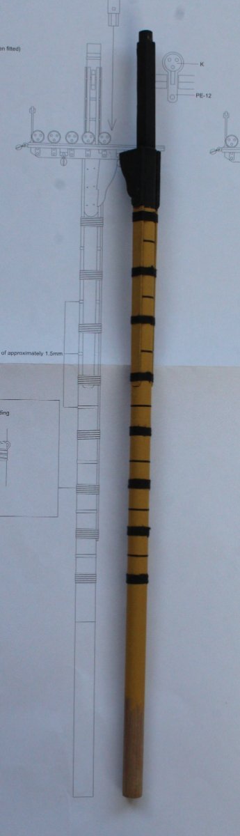
It did not take too much time or effort to complete the task.

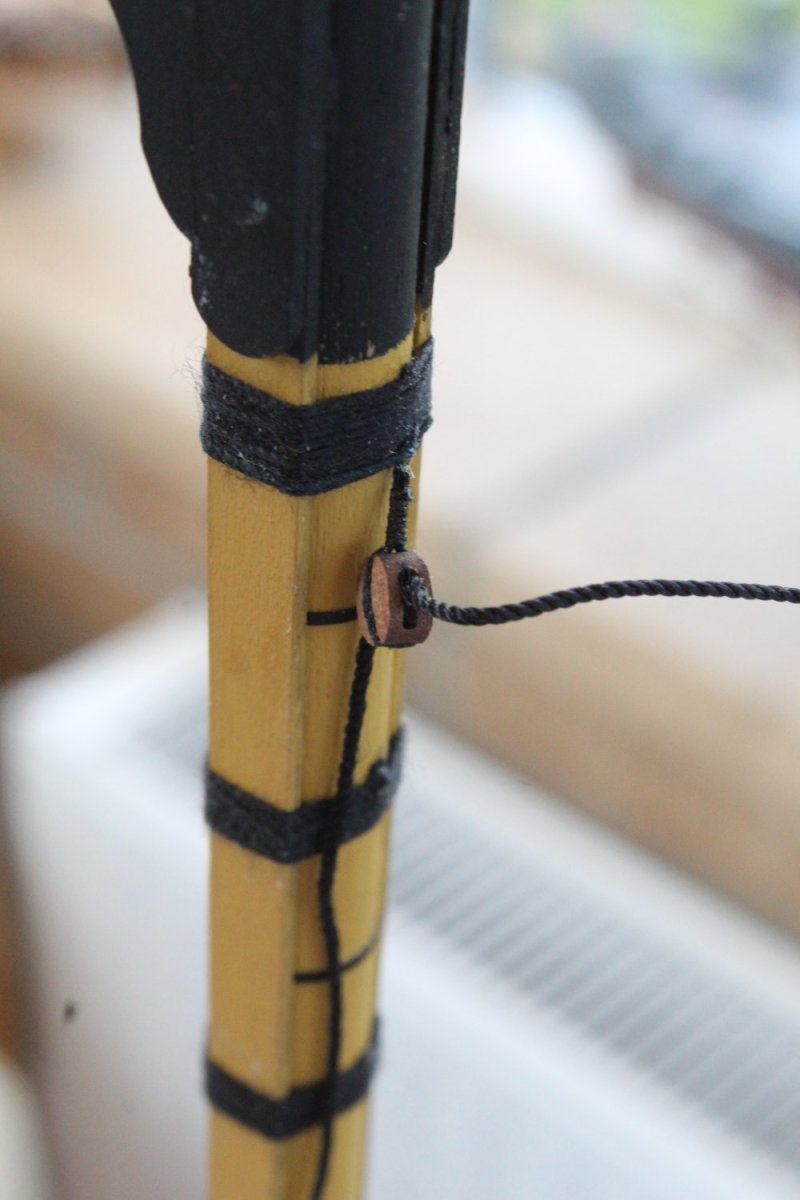
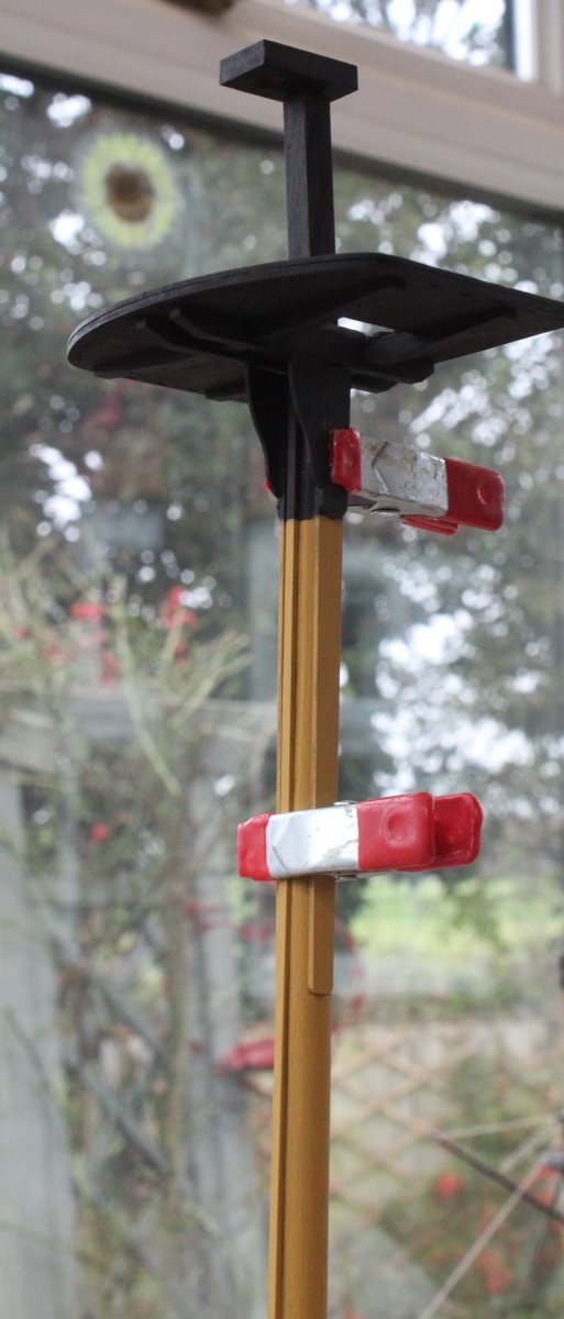
There is a 5mm single block to be secured to the mast below the upper most wolding. Once the block had be seized with some 0.25mm black thread it was secured to the mast using a simple clove hitch knot. I also made sure that a sample length of 1mm black thread could be fed through the block hole, as can be seen in the photo below.

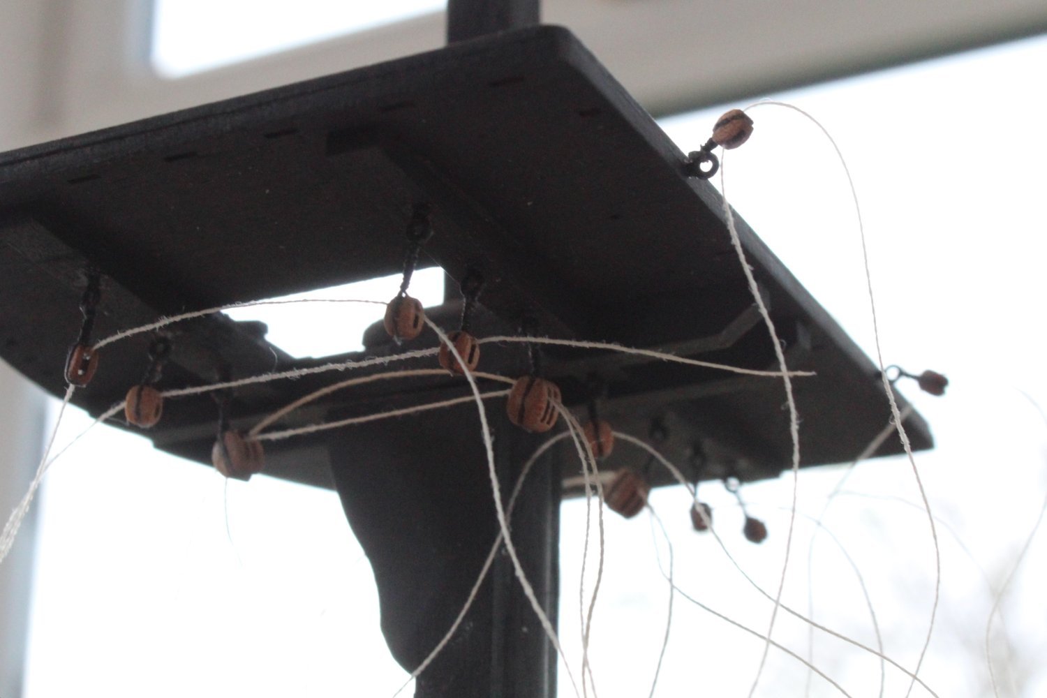
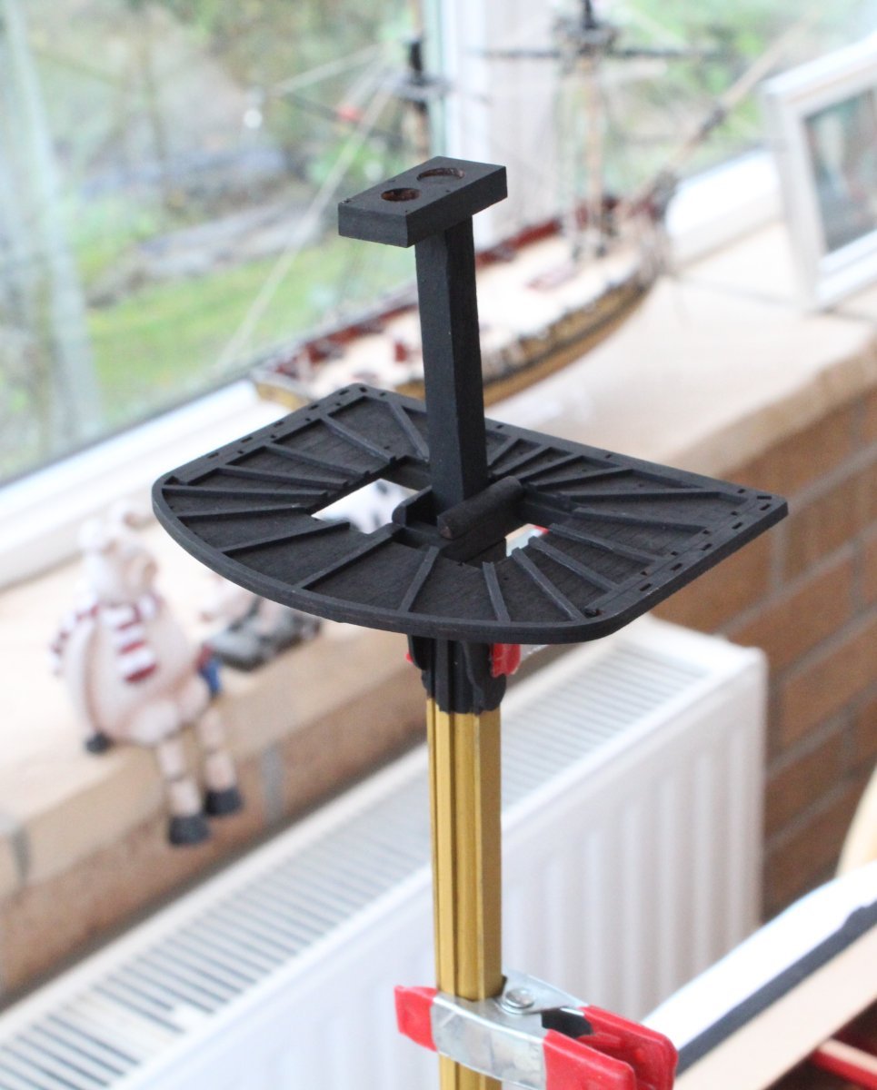
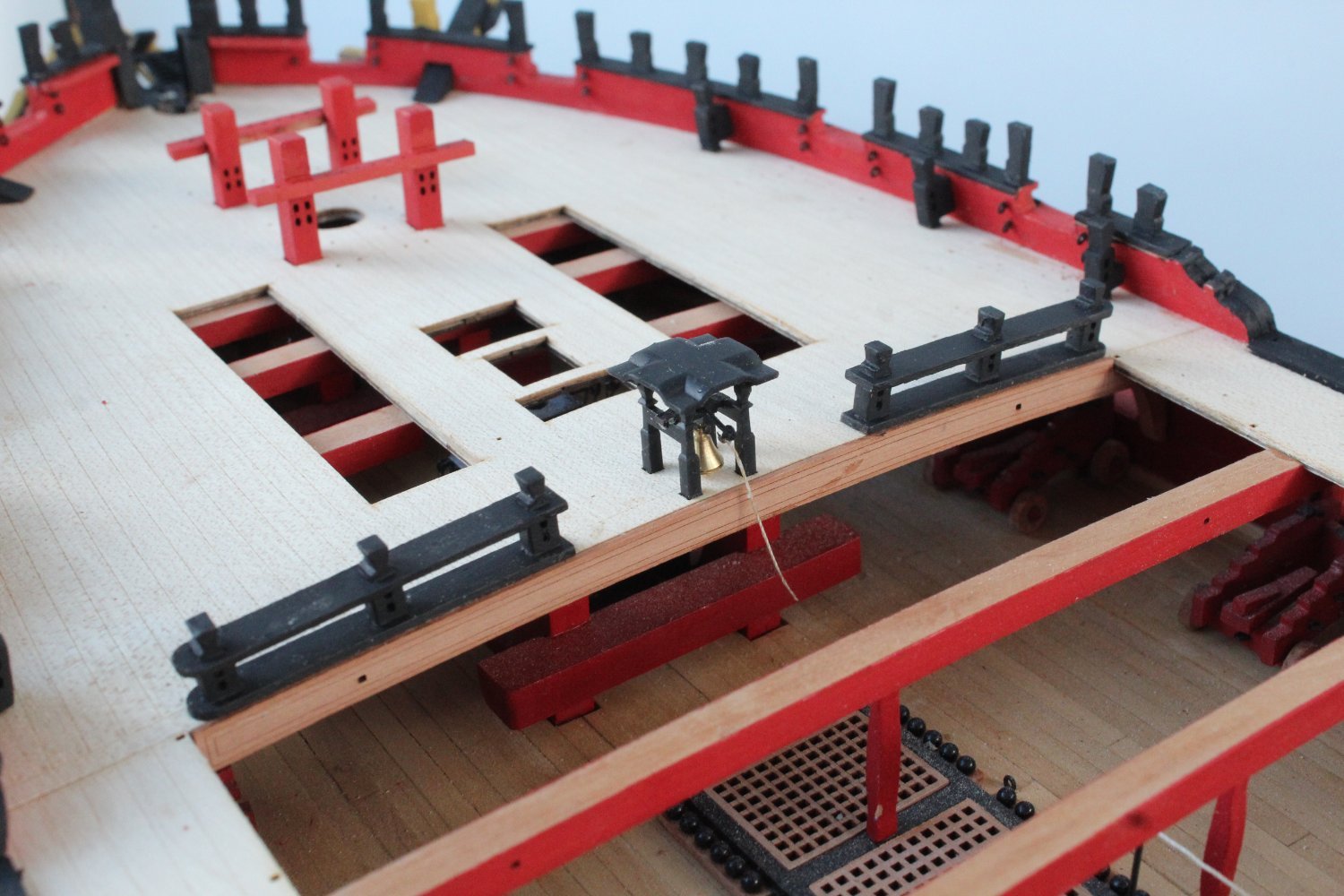
Foremast Platform
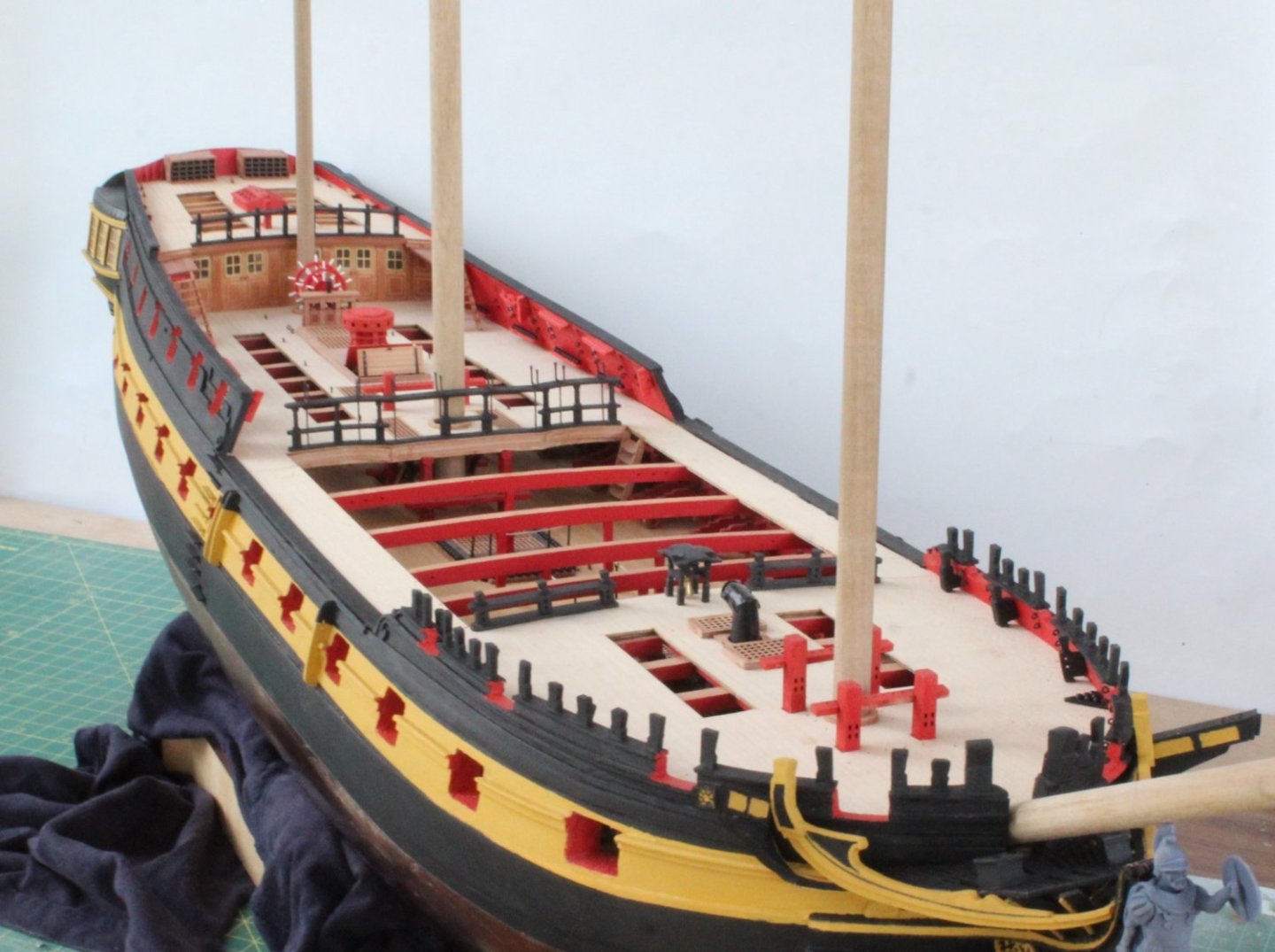
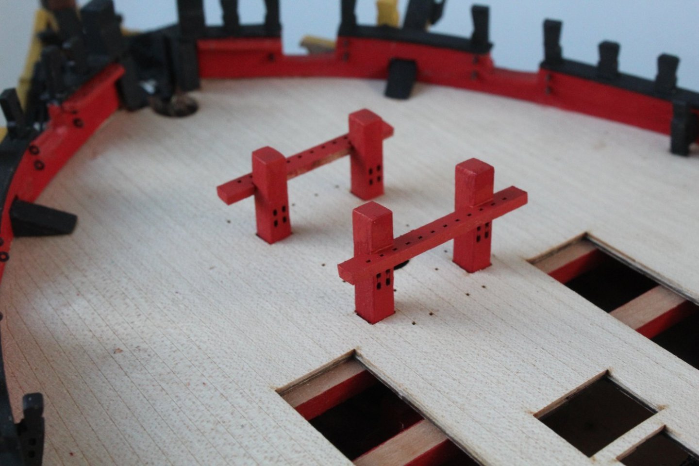
When working on the foremast platform I did wonder about the 8 square holes which did not seem to serve any purpose. Chris did kindly inform me that they are placements for temporary swivel gun posts, although rarely used in actual combat.
-
Foremast Lower Platform Blocks
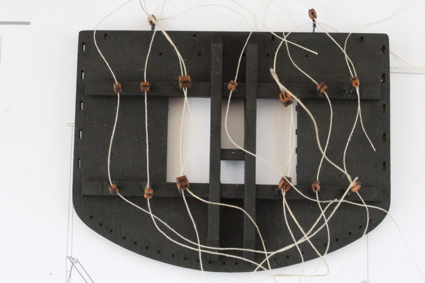
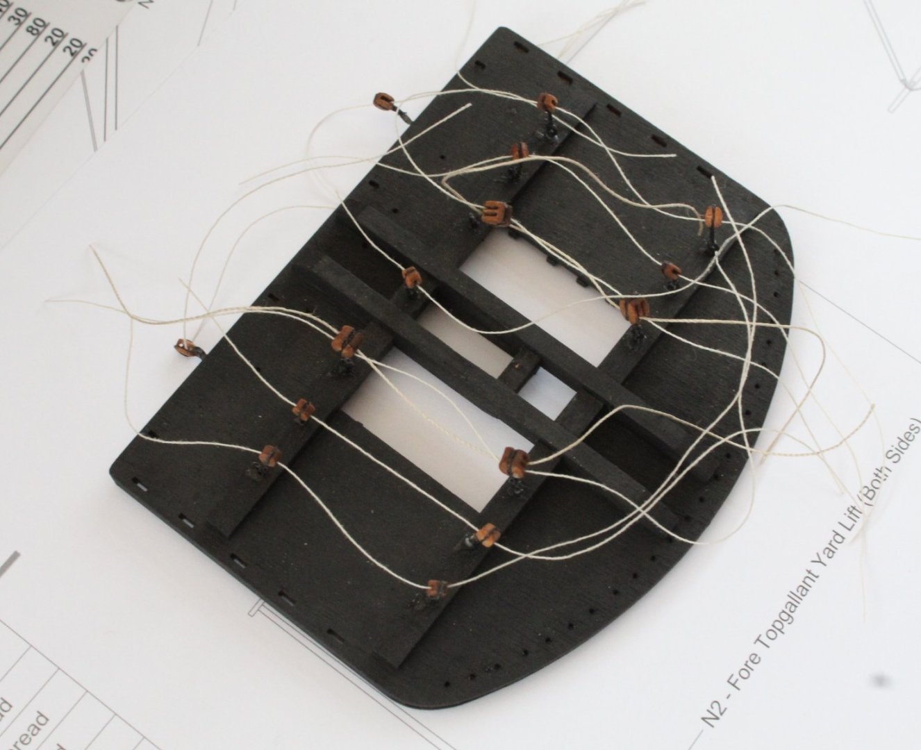
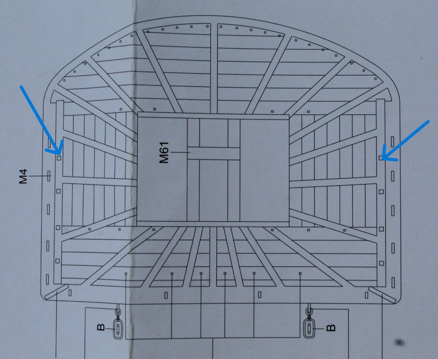
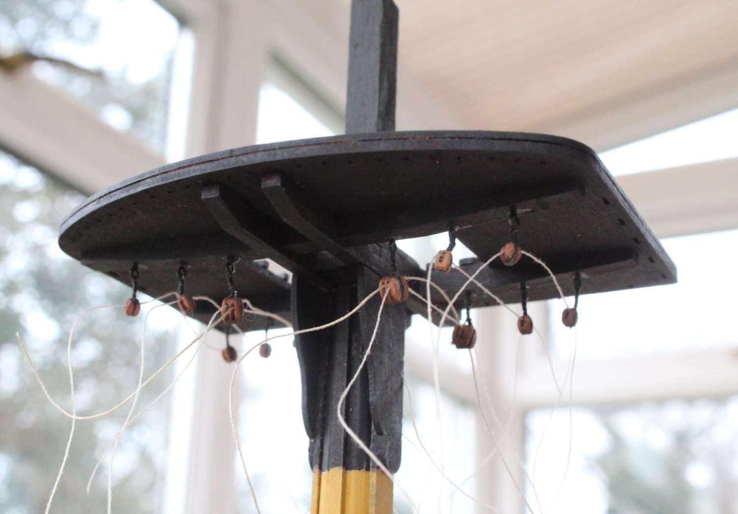
The lower foremast platform has a number of blocks fixed to it, via eyebolts. There are 11 x 3mm single blocks and 4 x 4mm double blocks.
It was quite a time consuming task to seize the block and then to add the eyebolt, using the method detailed in my last post. The key aspect with this task was to ensure the blocks were on the required alignment for the rigging, once the eyebolts are added to the platform. It was also important to check that the required rigging thread could be fed through the block holes. Once all the blocks were completed and added to the platform I did make some test threads. One end of each test thread was stiffened with ca. to aid the threading process. As can be seen in the attached photos I was able to fit the test threads. I have noted that the top right hand eyebolt is not fully seated, which has been fixed since taking the photos.


Thoughts On Moving Forward with Mast and Yard Rigging
Moving forward I am now going complete the work on the lower foremast, such as adding the wolding, adding the iron banding to the square mast section above the platform, adding the various mast blocks, adding the cleats, etc.After that I will prepare the foremast shrouds so I can add the foremast channels to the hull so the chainplates are aligned to follow the flow of the shrouds.
The normal process for rigging a model boat is to add the standing rigging, such as shrouds, ratlines, futtock staves, stays, etc. before adding the yards. I have always found it awkward to rig things like the yard lifts and truss pendants after the standing rigging has been added. I have often thought it might be easier to add the yards to the mast first but not sure if there will be other issues with adding the standing rigging with the yards in place. I noted that @ECK has adopted this approach on his Indy build. I am going to give this method a try on the foremast to see how practical it is. Fun time ahead.
- JeffT, Theodosius, p.hoek and 5 others
-
 8
8
-
It is interesting to see you are rigging the yards to the masts before adding the shrouds and stays. It is something I have thought about doing as the access will be much easier.
- chris watton, mtaylor and mgatrost
-
3
-
-
3 minutes ago, paul carruthers said:
I always pull my thread thro’ beeswax and then hit with a hair dryer when under tension, minimises the fluff.
Does the hairdryer warm air help the wax to flow thus smoothing out the thread more and perhaps also making the line less flexible?
- mtaylor and paul carruthers
-
2
-
Lower Foremast Work
I have continued working on the lower foremast. The next task was to paint the mast, front fish, cheeks, platform and cap. The next two photo's shows the painted mast assembly in place, noting that I have not glued any of the pieces together at this stage. This is because the simulated iron bands need be added before the front fish and cheeks are added. Please note that the cap does fully locate but has not been fully pressed home in the photo below.


I opted to use black tape to simulate the iron bands as I found a suitable cheap option on Amazon.
With the simulated iron bands in place the front fish was then glued to the foremast.

Once the glue had been given time to cure the two cheeks were glued in place. The platform has not been glued in place at this stage as there is some more assembly work to undertaken on the platform,
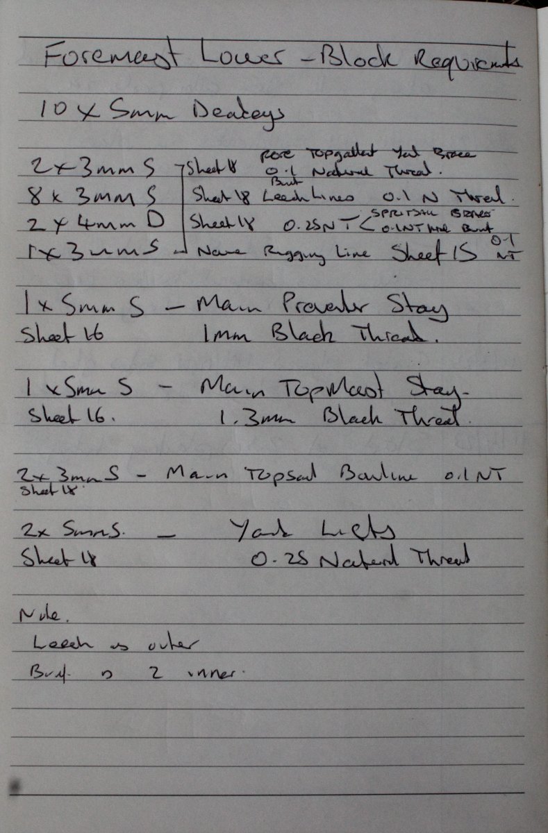
There are a number of different blocks required for the foremast / platform. I like to make notes of the block requirements. These notes will include the block type, the rigging thread requirements, rigging plan sheet reference, etc. I find this pre planning step really useful, especially with regards to the rigging thread requirements. I like to ensure that the required thread can be fed through the block holes before the blocks have been added. I find it is easier to slightly enlarge the block hole (if required) at this stage.
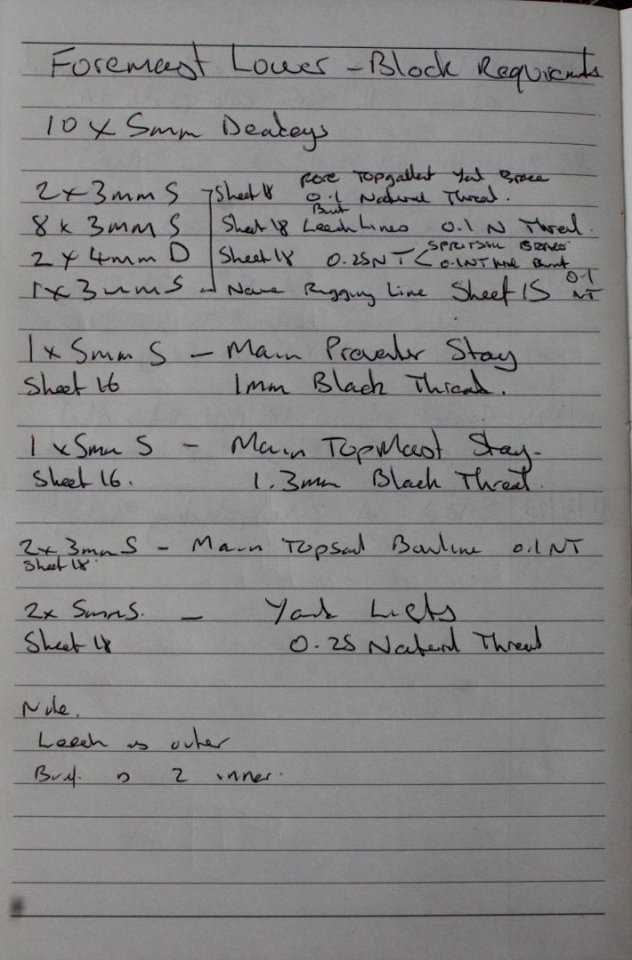
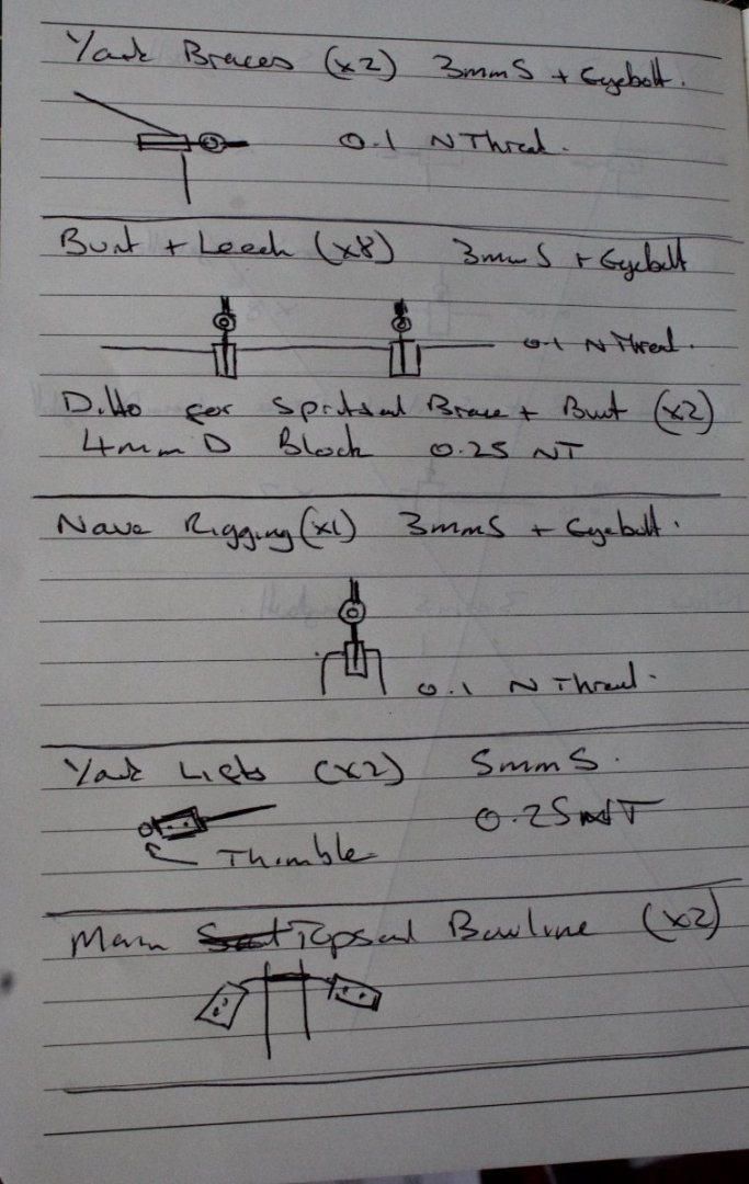
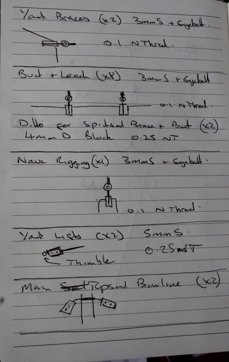
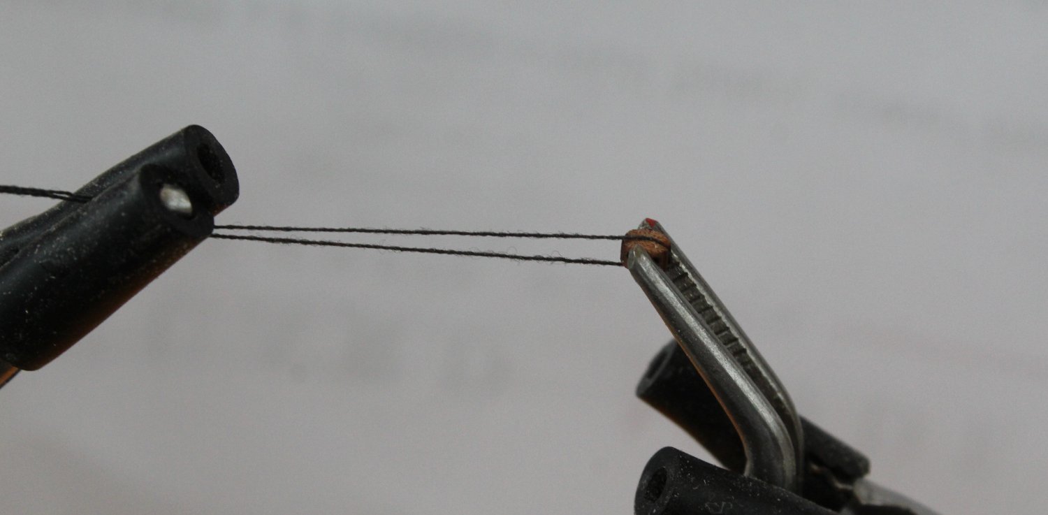
Starting with the two 3mm single blocks required for the fore topgallant yard braces I have noted that these blocks will require an eyebolt and that the rigging thread will be 0.1mm natural. I have covered my method of rigging blocks in some of my other build logs but I have added a brief description herein. Using the quad hands the block is held in place and a length of black thread is wrapped around the block.
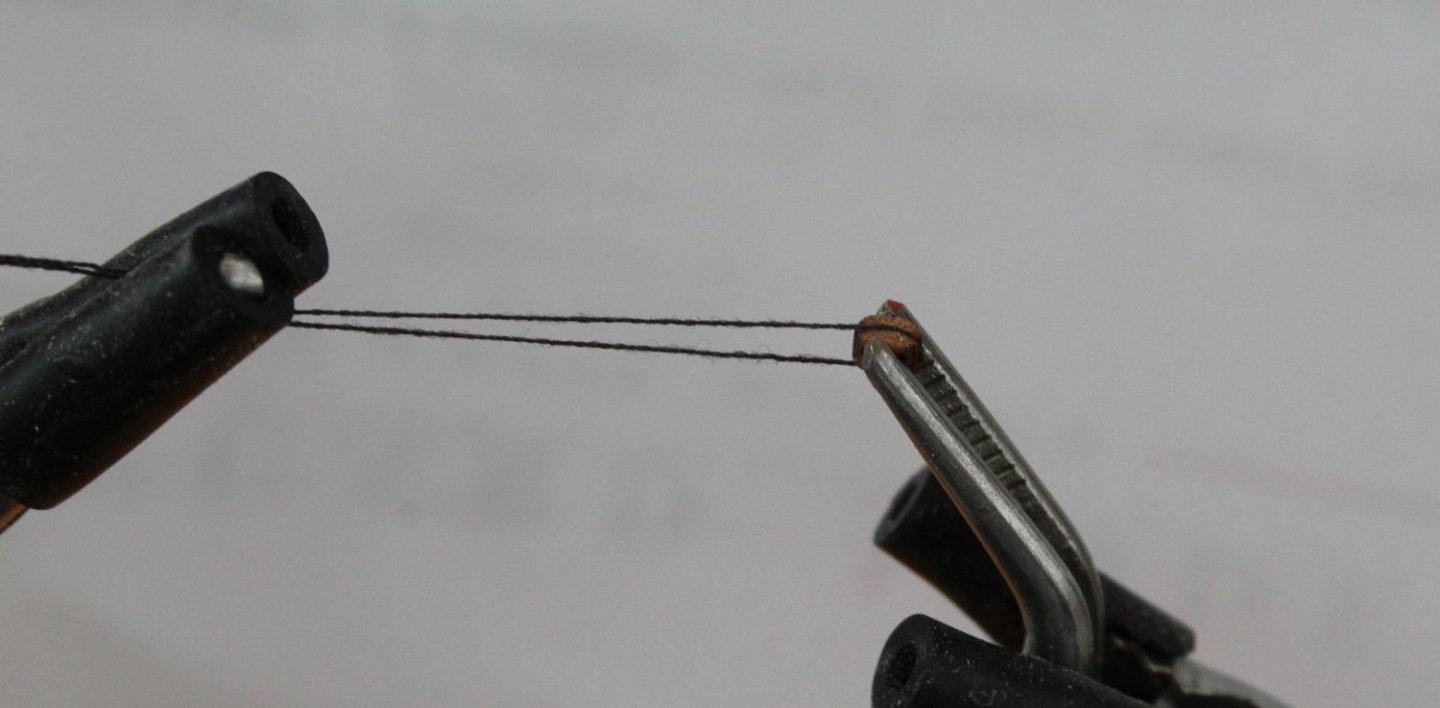
I use fly tying thread for the seizing with a sequence of 10 lower and 10 upper half hitch knots.
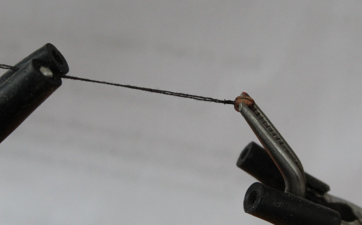
I then cut off one the free thread ends and passed the other free end through the eyebolt and then clamped it to the side of the block whilst I add another set of lower and upper half hitch knots. The excess thread is then trimmed. The end result is a nicely sized block complete with eyebolt.
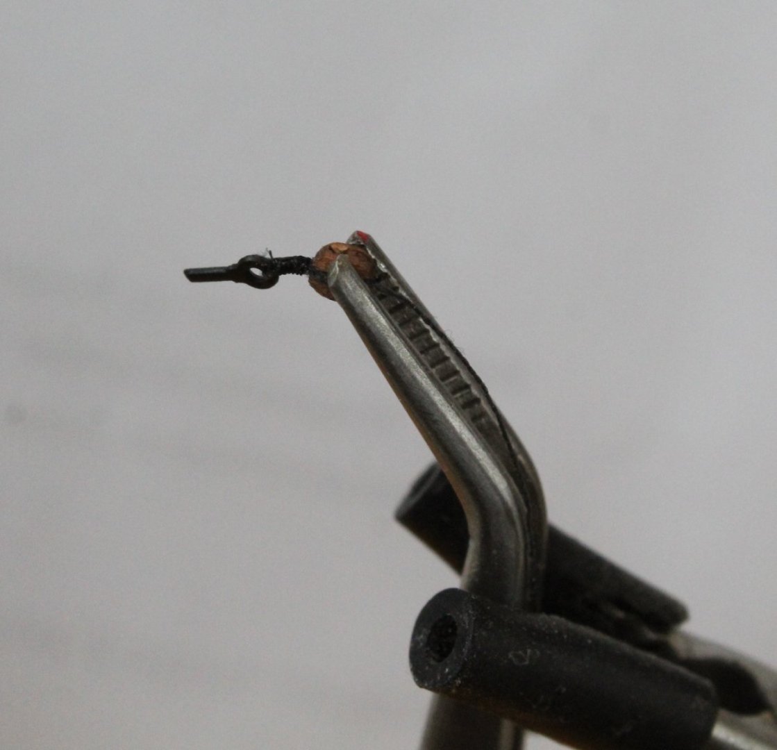
Next I check that the required thread will pass through the block hole. I did find it necessary to run a micro drill bit through the hole before the 0.1mm natural thread would pass through.

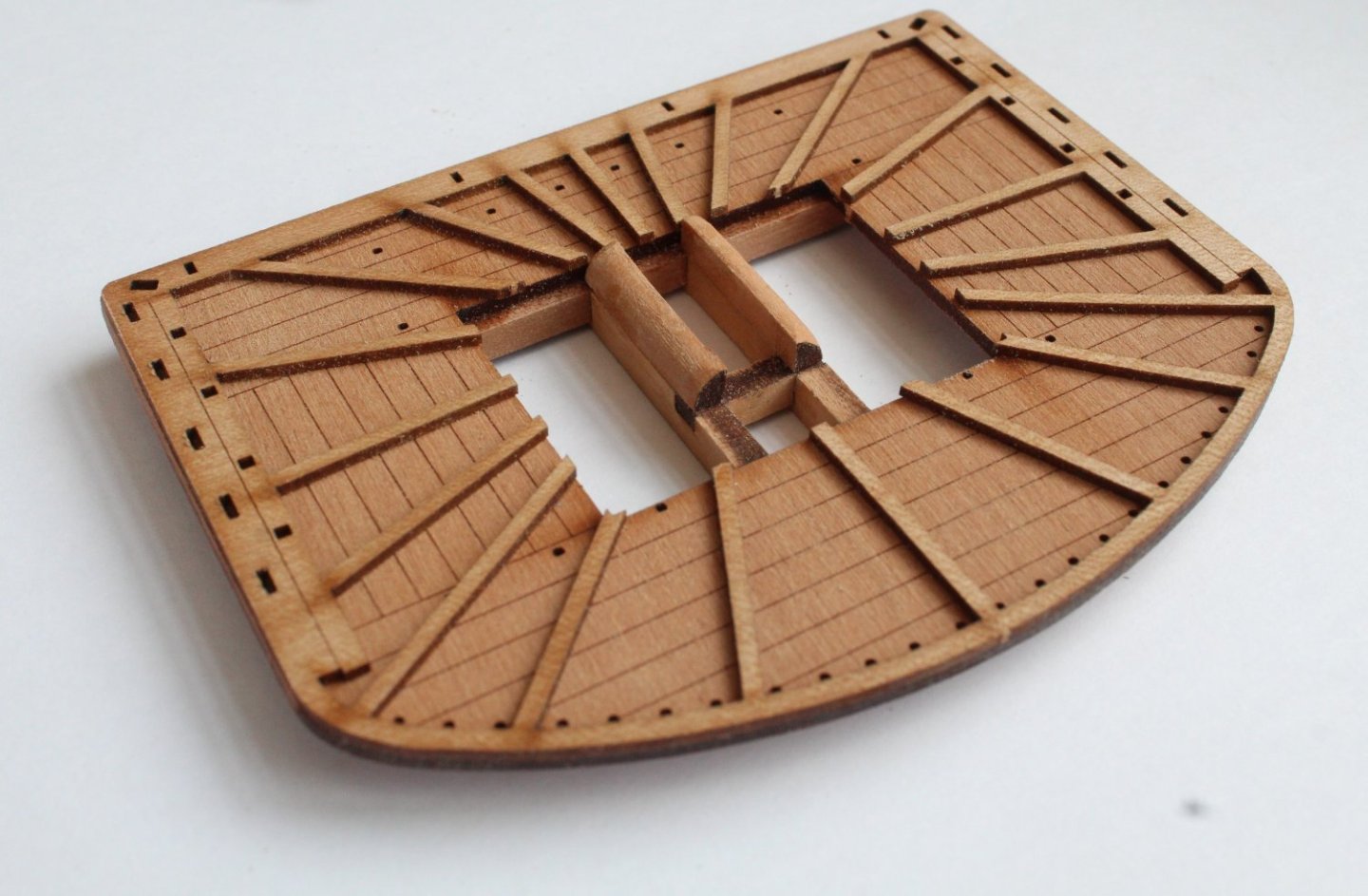
The two block are then test fitted to the platform, making sure the eyebolt and block alignments match the plan / rigging sheet requirements.
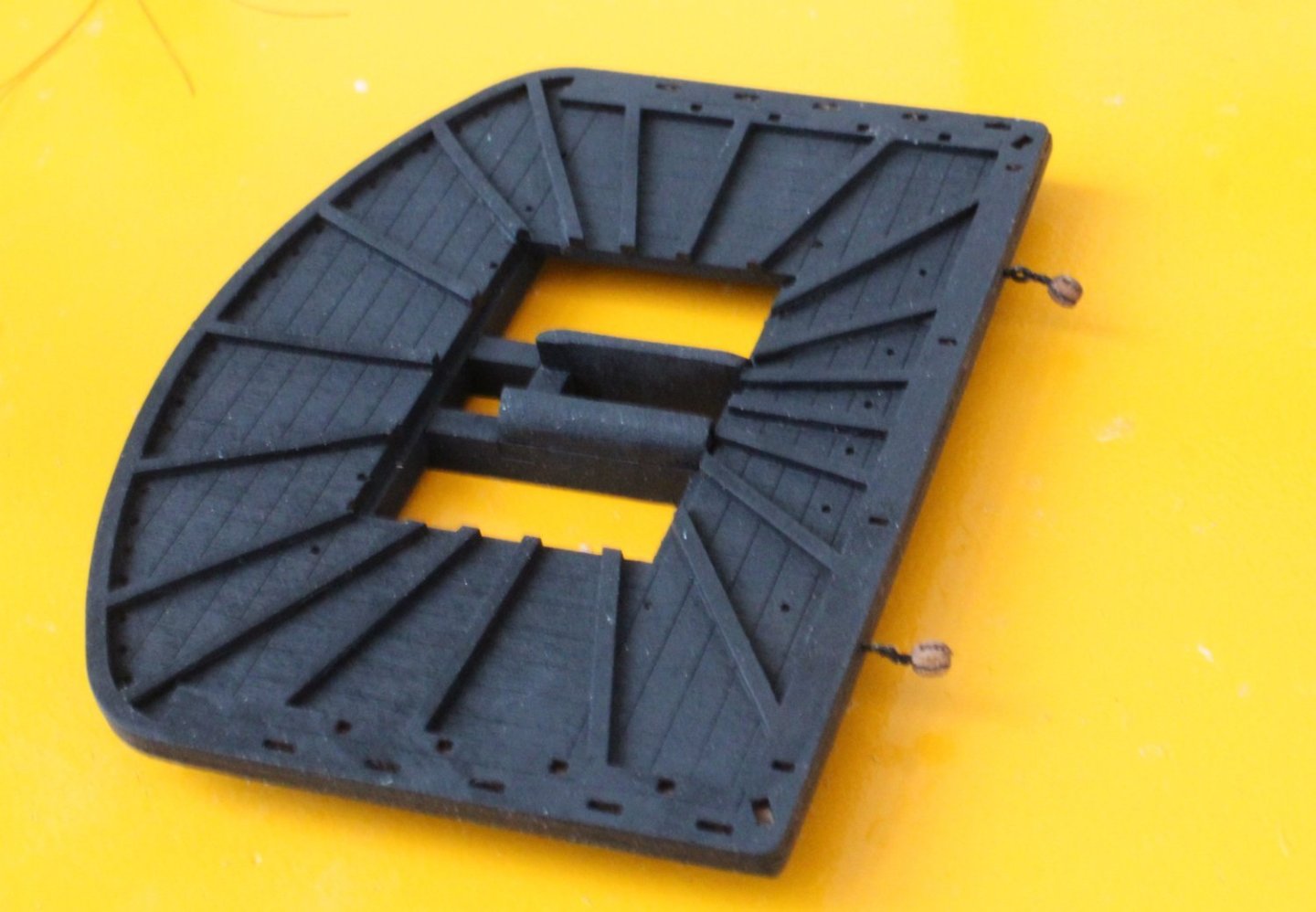
Next I will be the adding the various 3mmS and 4mmD blocks required for the leech, bunt and nave rigging. They all require seizing to eyebolts which takes time.
I also need to investigate to see how the two 5mmS yard lift blocks are secured to the top of the foremast around the cap area.
I am tempted to seize the two 3mmS topsail bowline blocks to either end of one length of thread which can then be secured to the foremast with a clove hitch knot.
Progress is going to be slow and steady over the next few days.
- mtaylor, ECK, KARAVOKIRIS and 5 others
-
8
-
I can't offer much advice. When I rig those blocks I try to ensure the blocks at each end of the thread are in the same alignment. I then add the thread to the yard, using a clove hitch knot. As I tighten the knot I check both blocks are aligned correctly.
As Chris advised diluted pva also on the lines.
- AJohnson, DB789, Thukydides and 1 other
-
4
-
1 minute ago, ECK said:
I used black tape for the iron banding. After assembly I painted the lower mast then stretched the tape around, pushing into the corners of the hollows then with a scalpel trimmed the edges.Taping before assembly and painting would require a steady hand to touch up the lines with black paint.
Thanks.
-
-
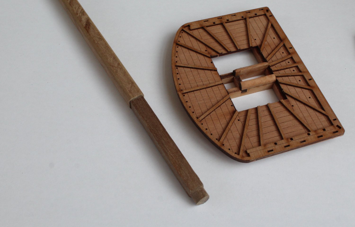
Foremast Construction WIP
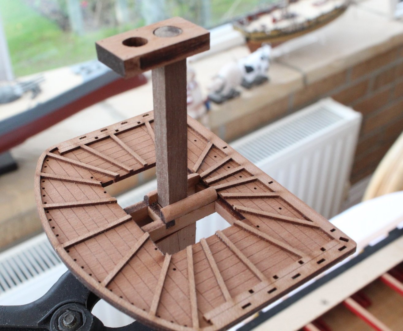
I have started work on the lower foremast. The first task was to construct the platform. It was a simple task to assembly.
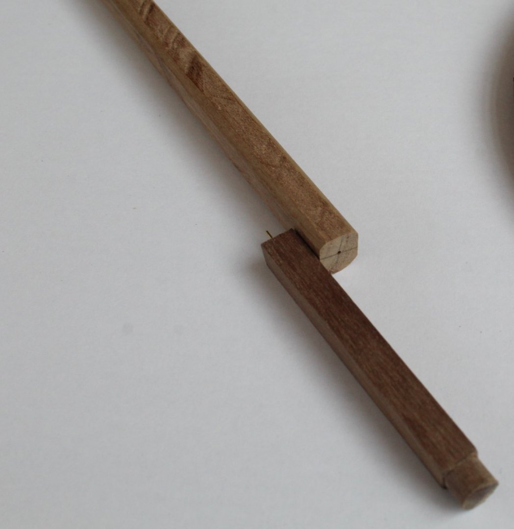
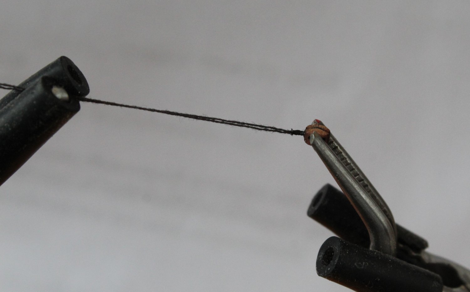
The lower foremast is made from a length of 10mm dowel. The upper section is 60mm long and comprises 55mm as a 7mm x 7mm square section and the top 5mm is set as diameter 7mm. My Proxoon circular saw was my tool of choice for this task.

I did have some 8mm x 8mm square material so I decided to use that to make the top section using the saw to trim 1mm from two sides. This can then be pinned in place on the 10mm dowel. Using the Proxxon saw set for a 1 mm cut I added the flats to the dowel for the two checks. I also added a flat for the front fish.

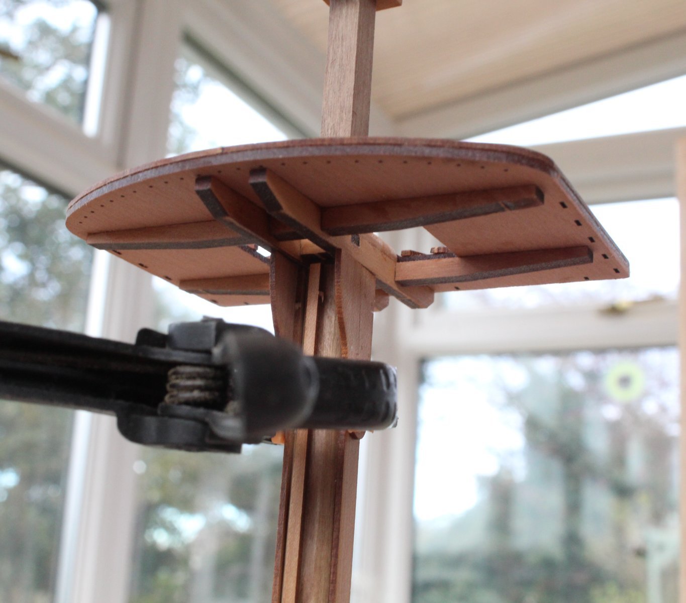
Before gluing the various parts in place I used some clamps to see how the lower foremast assembly would look in situ.
The square section is a good fit with the platform and with the cap

The front fish look good.

Bibbs also clamped in place
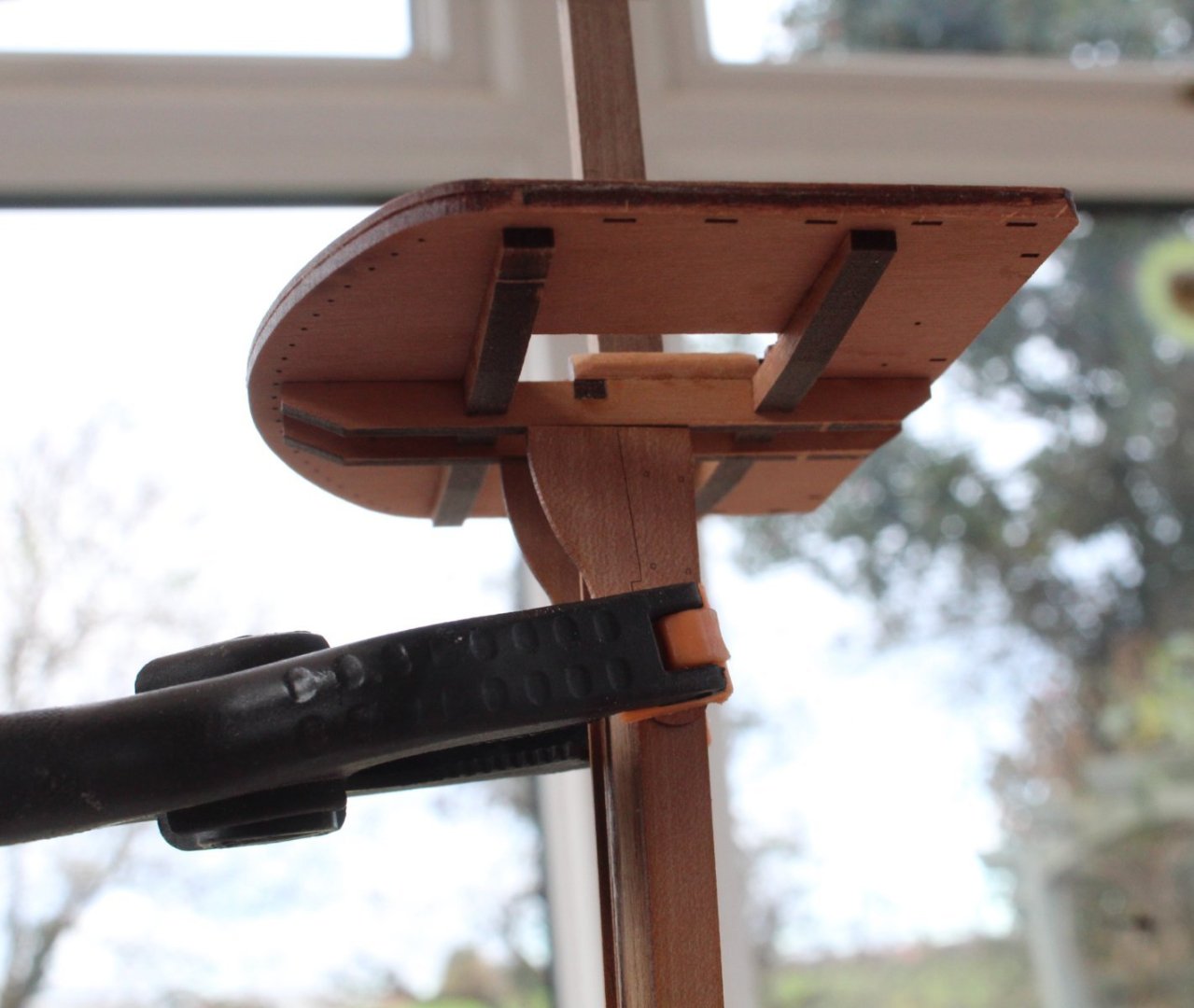
The top cap is a good fit also.
The black card iron bands needs to be added before the cheeks, bibbs and front fish are glued in place as the banding sits under these parts. My current thinking is to paint the mast yellow, then to add the black card iron bandings before adding the cheeks, bibbs and front fish.
However when looking at both @ECK and @Kevin build logs it would seem they fitted the simulated bandings after the foremast assembly and painting. I am assuming, if this is the case, that they only fitted the black card iron banding between the checks and front fish.
-
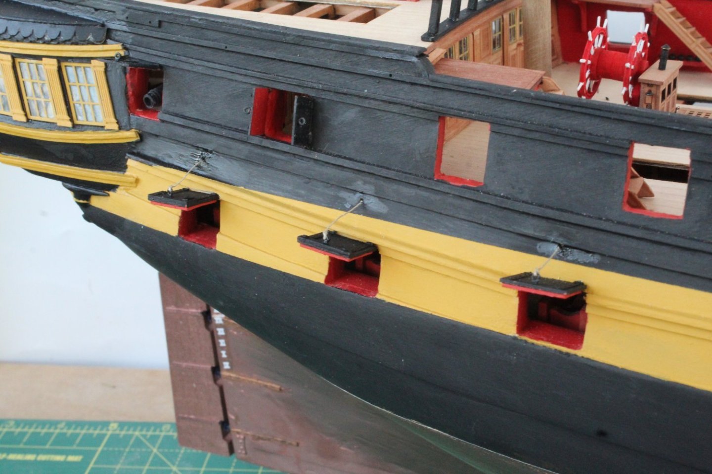
Channel Update
I have now experimented with adding a shortened middle chainplate for the rear most channel strop arrangement. With the shortened middle chainplate it will allow the lower chainplate to be fixed to the hull above the gunport.

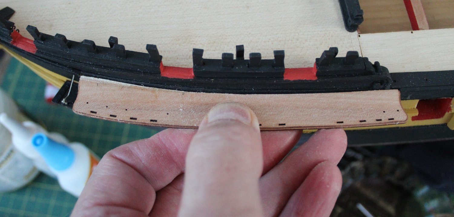
I have also be working on the foremast channel. I did add some additional material to the bow end of the channel to fill the gap that existed between the hull and the channel. I am now happy that the channel sits flush with the hull.
I am now going to turn may attention to making the lower fore, main and mizzen masts.
- Rustyj, chris watton, KARAVOKIRIS and 8 others
-
11
-
12 minutes ago, ECK said:
I choose that area as I found the angle and distance otherwise very tight. I found using the appropriate dowel in the mast hole and string gave a pretty good angle for the chains. I 'll find out how well next week when I start doing the shrouds.
I was thinking the same but I am going to make some shortened middle chainplate links to see what looks best.
-
7 minutes ago, RossR said:
Thanks for sharing you thought process on this step. I am at a similar point in my Frigate Diana build and you validated some of my decisions. I am fabricating my chain plate out of black annealed wire as my kit suggested using a single strand of brass wire. I didn’t like that approach. spent quite a bit of time making different sized pieces trying to find the right combination of components to fit right.
Your work is fantastic. I hope one day my work will look this good.
Many thanks for your comments, it is much appreciated. Experience has taught me to take my time with this aspect. Once I have sorted out the foremast channel aligment issues I will construct the masts.
-
Channel work and thoughts
This is no a build progress post, it is my just detailing some of my thought processes.
When fitting the channels I think it looks nice if the chainplate links follow the flow / direction of their respective shroud lines. Therefore I find it is better to build the masts before fitting the chainplate links so that each shroud line flow can be determined.
Also when looking at the chainplate links and strops arrangements for the Indy I am more inclined to fit the chainplates to the deadeye strops before the channels are added to the hull as I think it will easier to do that than after the channels have been fitted to the hull.
This means that my next build stage will be the production of the fore, main and mizzen masts.
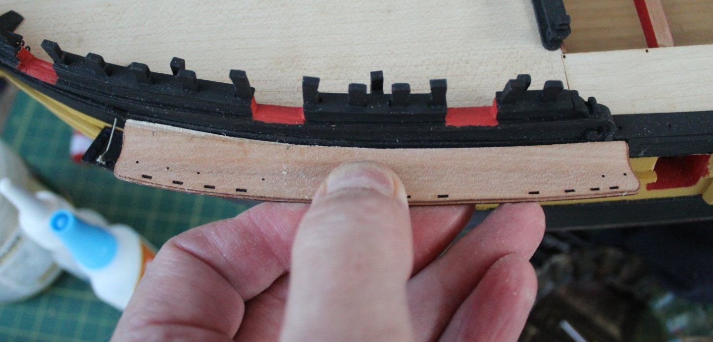
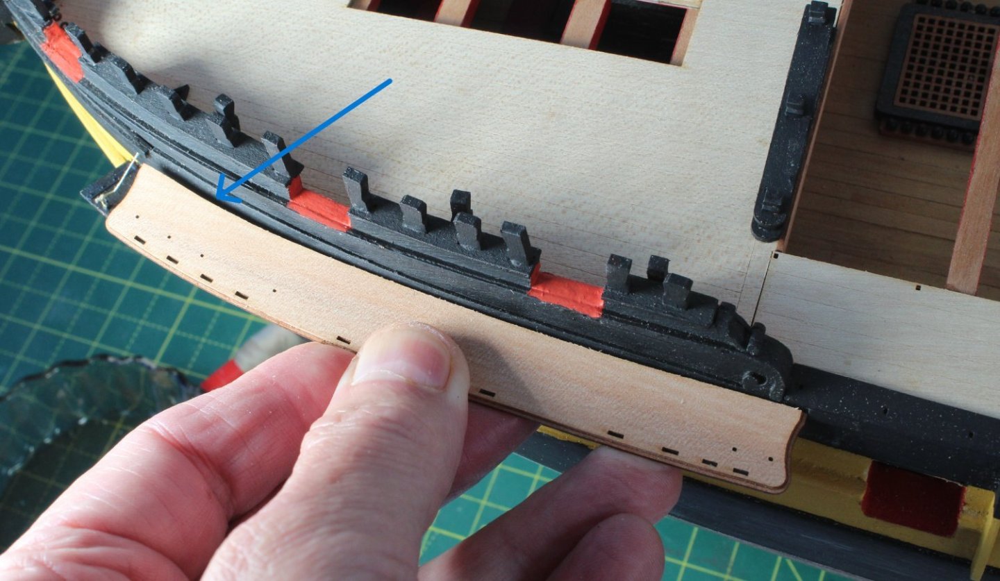
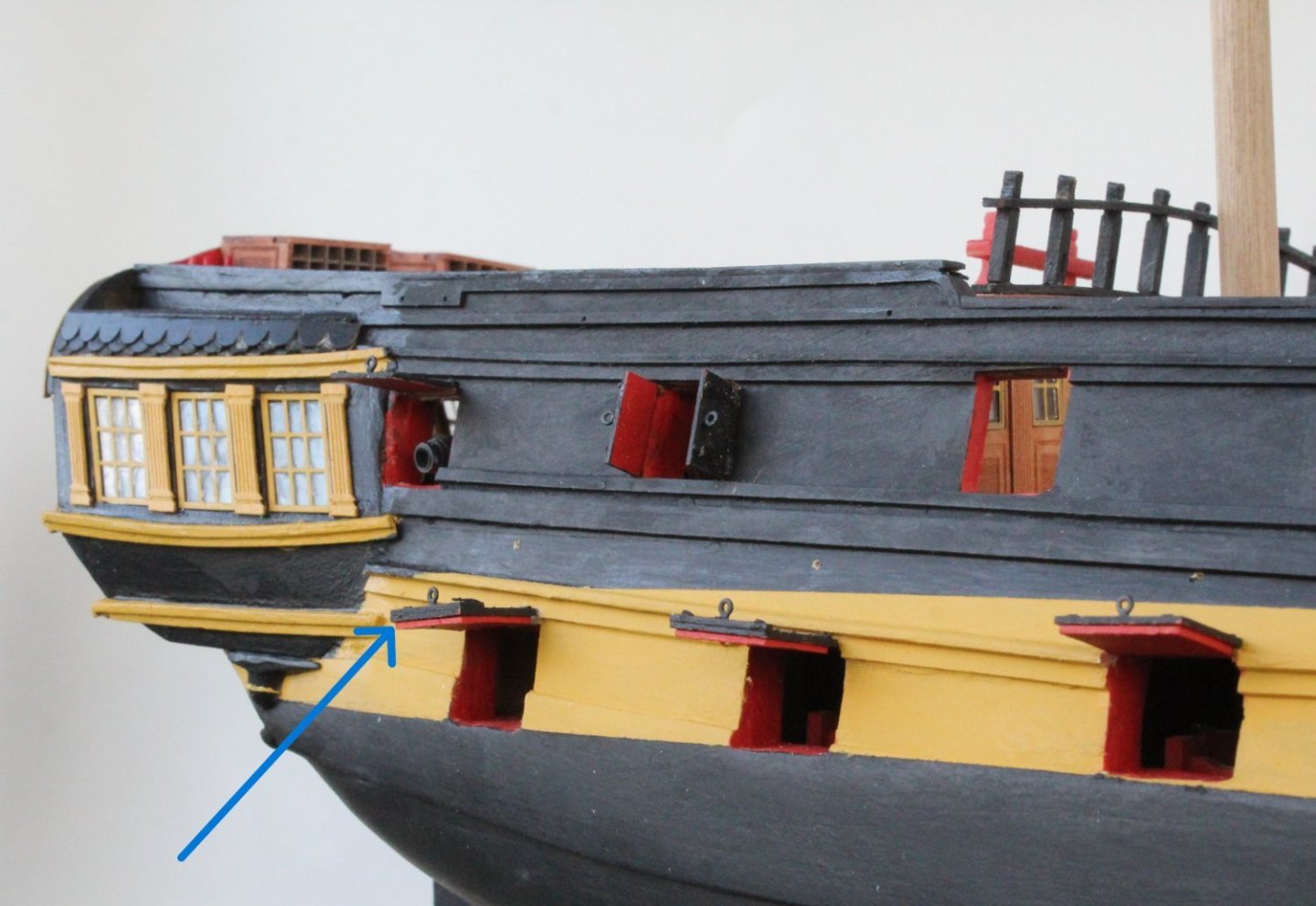
However before starting work on the masts I decided to spend a bit of time checking the fit of the channels to the hull. Everything looks good except the channel for the foremast. As can be seen when the channel is offer up to the hull there is a gap, as indicated by the blue arrow. I will need to sort this out before moving on to building the masts.
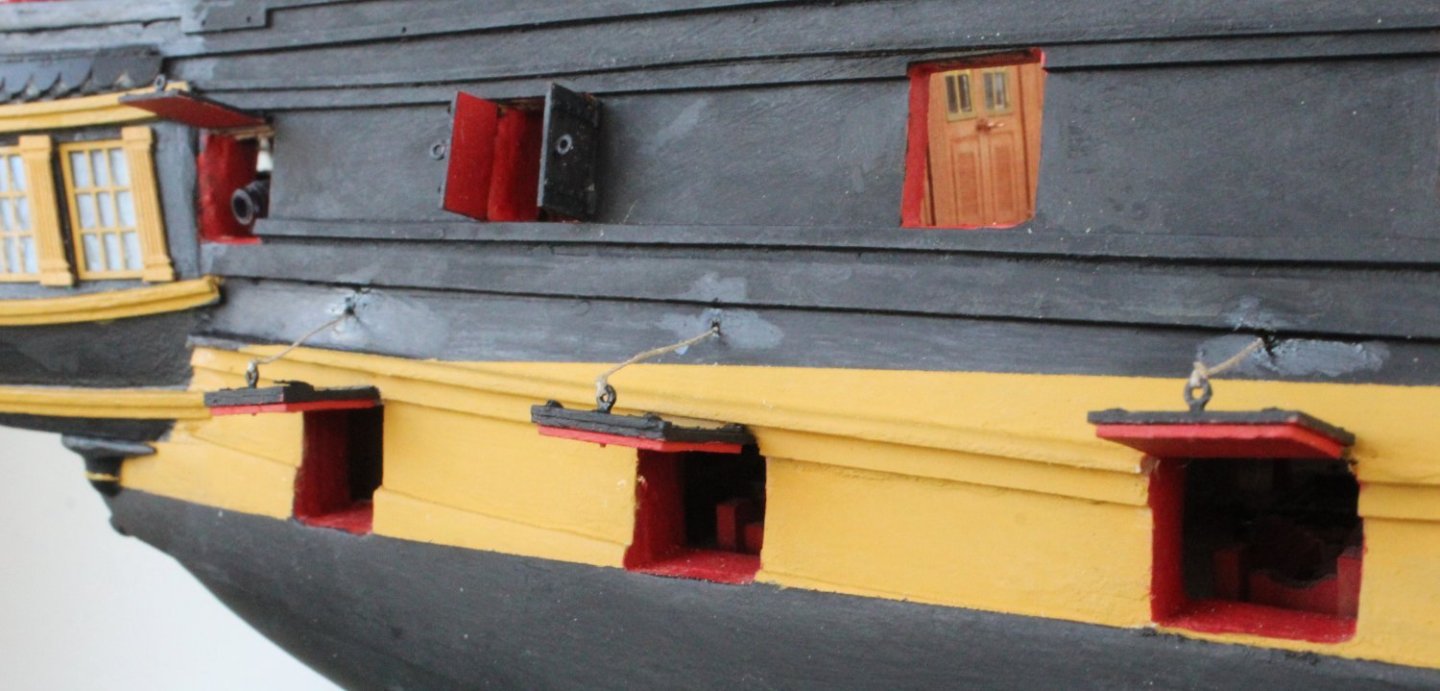
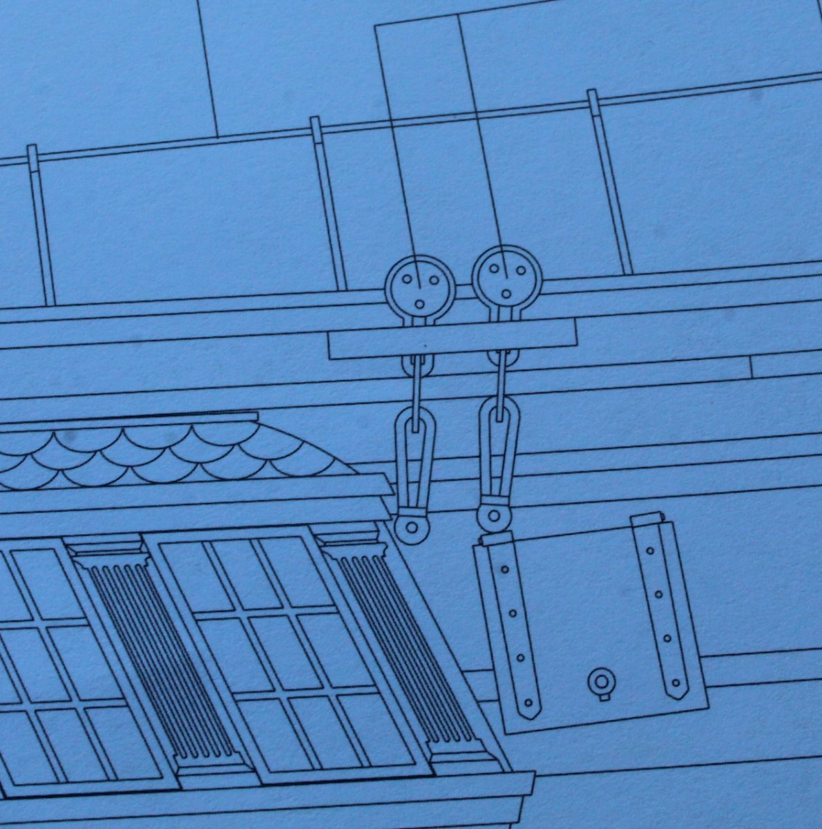
I did not fit one of the gunport lids as I was a bit concerned with it interfering with the fitting of the chainplate to the rear most channel. According to the admiralty plans (shown below) this should not be an issue as they will be terminated above the gun port.
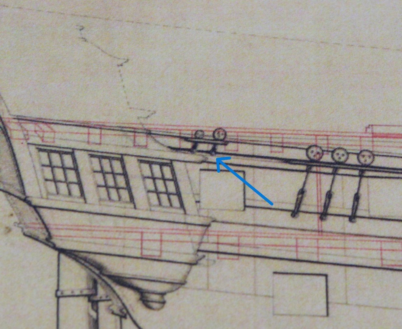
When looking at the kits plan sheets this also seem to be the case. So far so good.

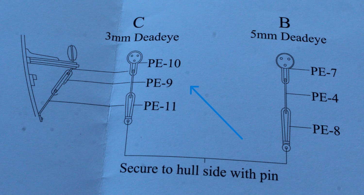
Next I looked at the assembly requirements which is shown as a type C arrangement with two chainplate links (PE9 and PE11).
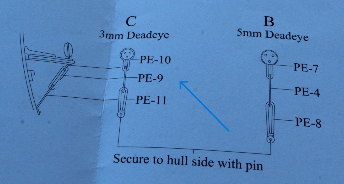
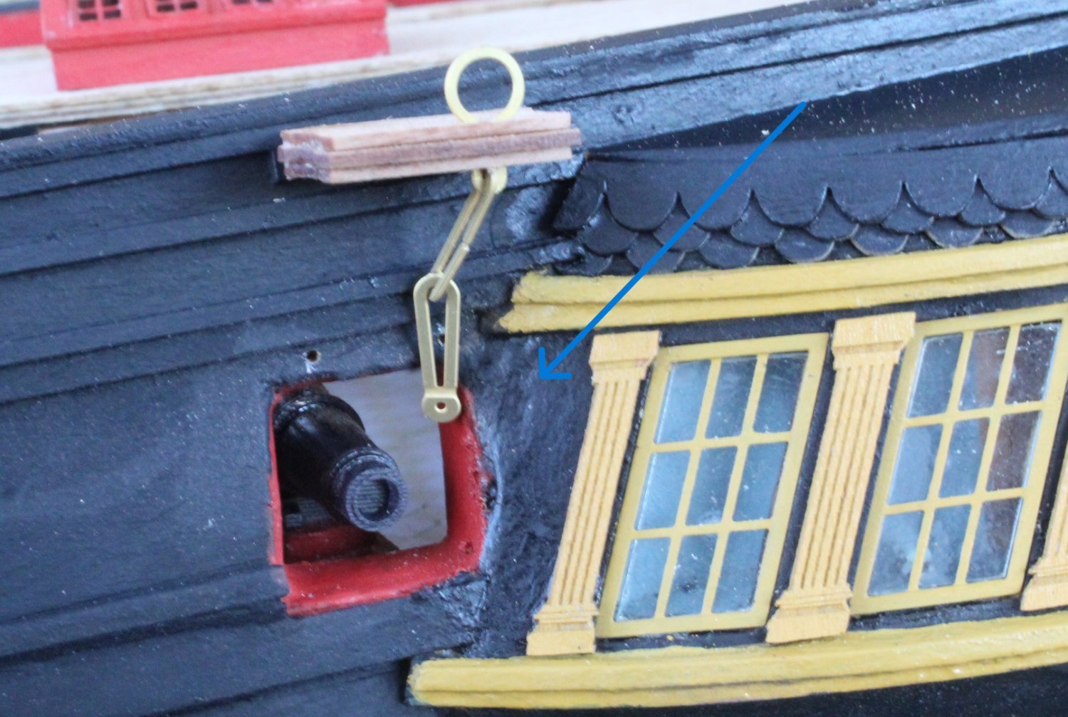
With a test fit (as shown below) the chainplates will terminate below the level of the gunport. I noticed that ECK terminated both chainplates in the area indicated by the blue arrow.

When looking at the prototype build it would appear that Jim fitted one to side and then added a shortened middle link, as indicated by the blue arrow.
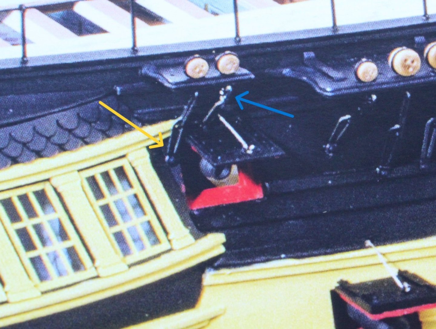
I more inclined toward a shortened middle link solution.
-
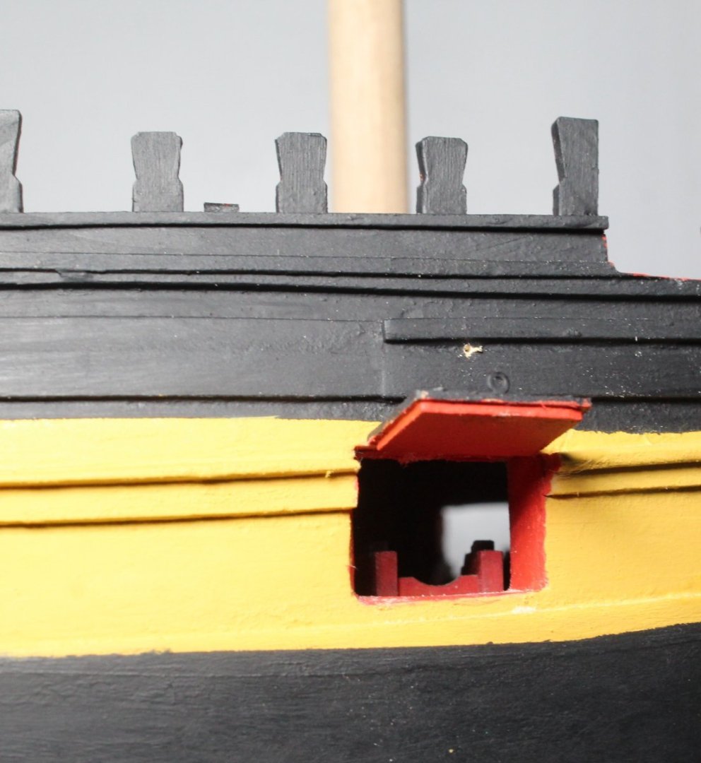
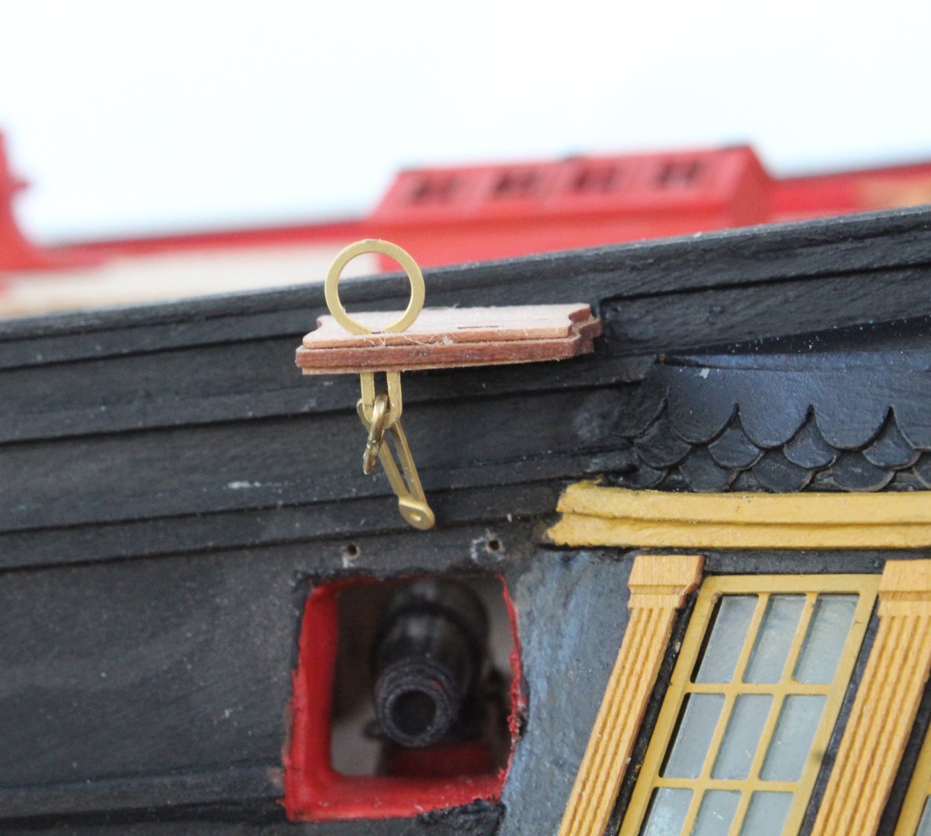
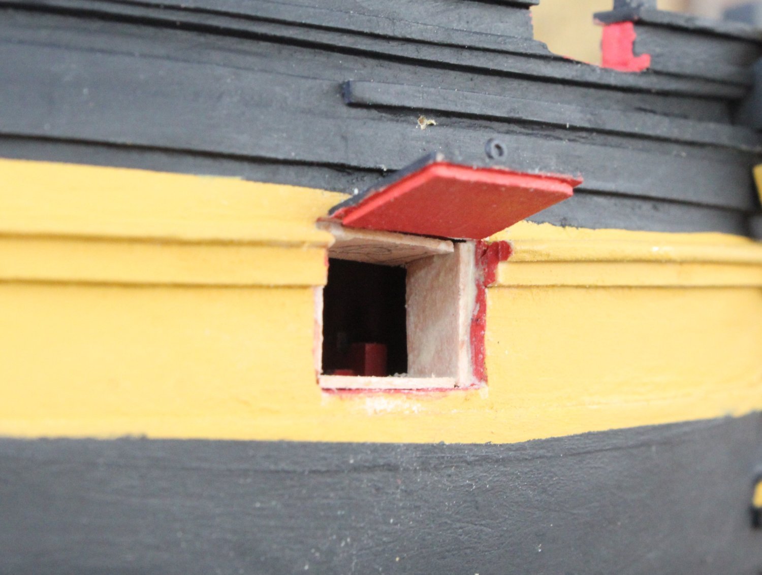
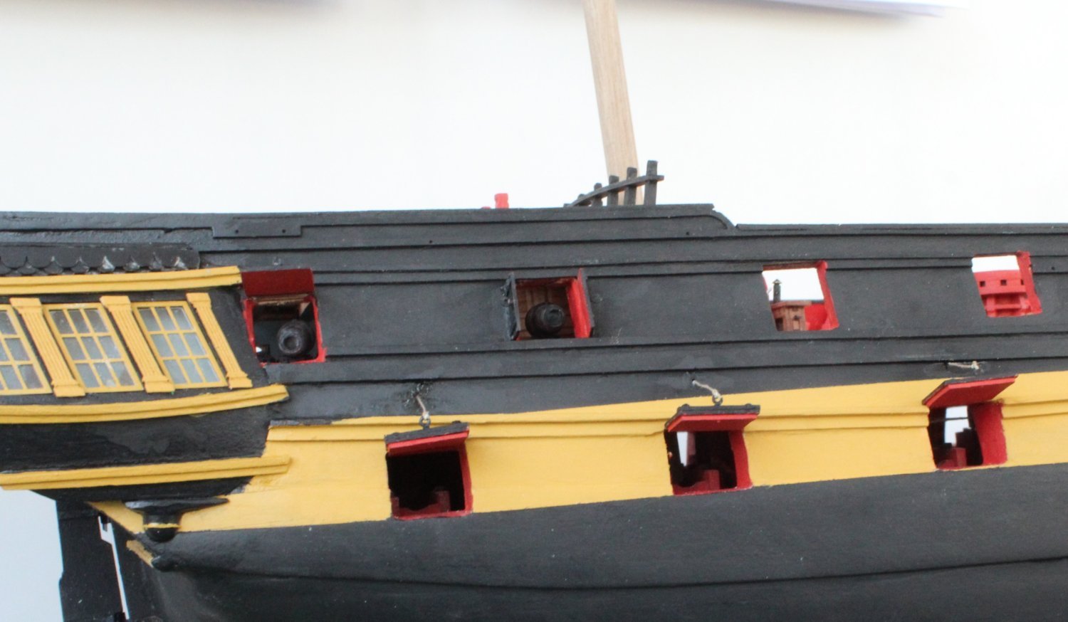
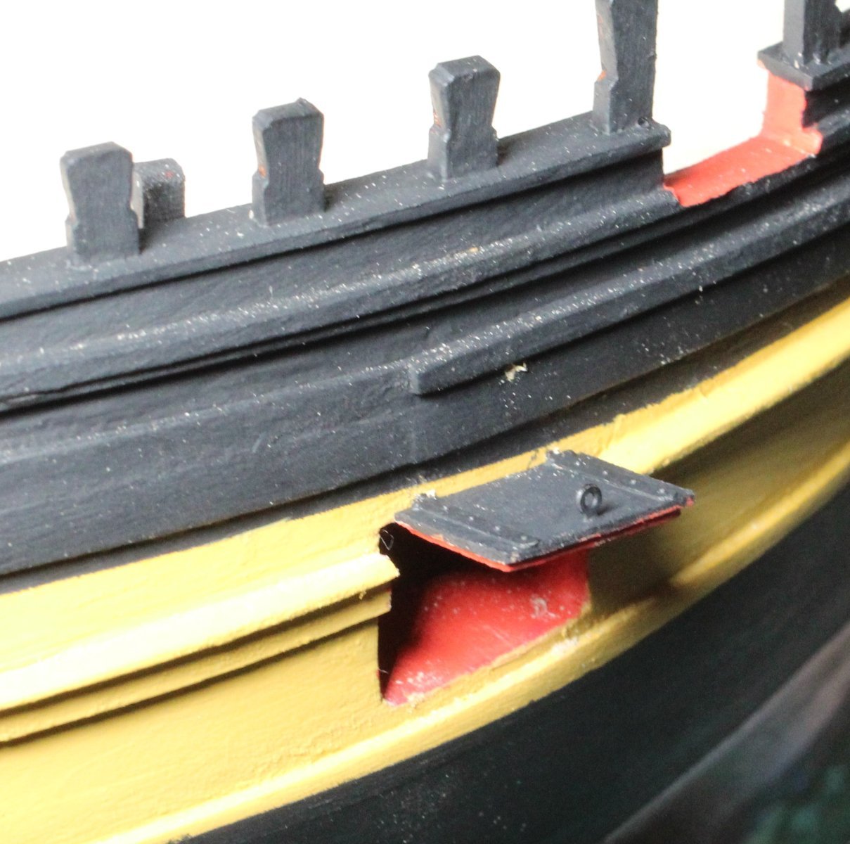
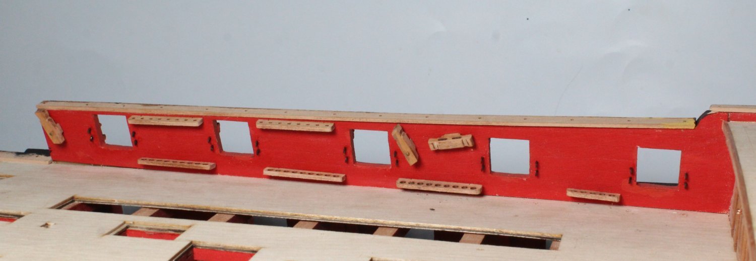
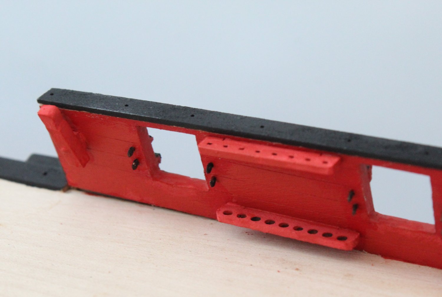
Gun Port Lid Installation
Following on from my last post I continued the work with installing the gun port lids by adding the linings to the bow gun port.

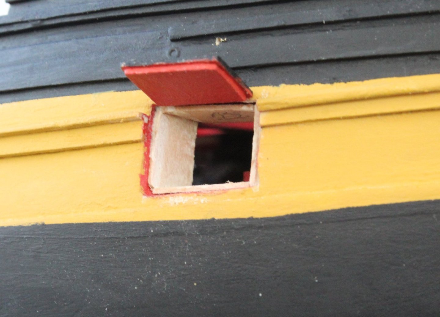
The linings needed to be painted red.

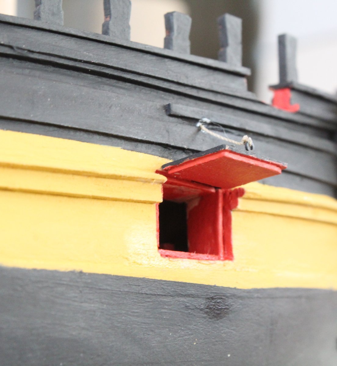
The bow gun port complete with lid

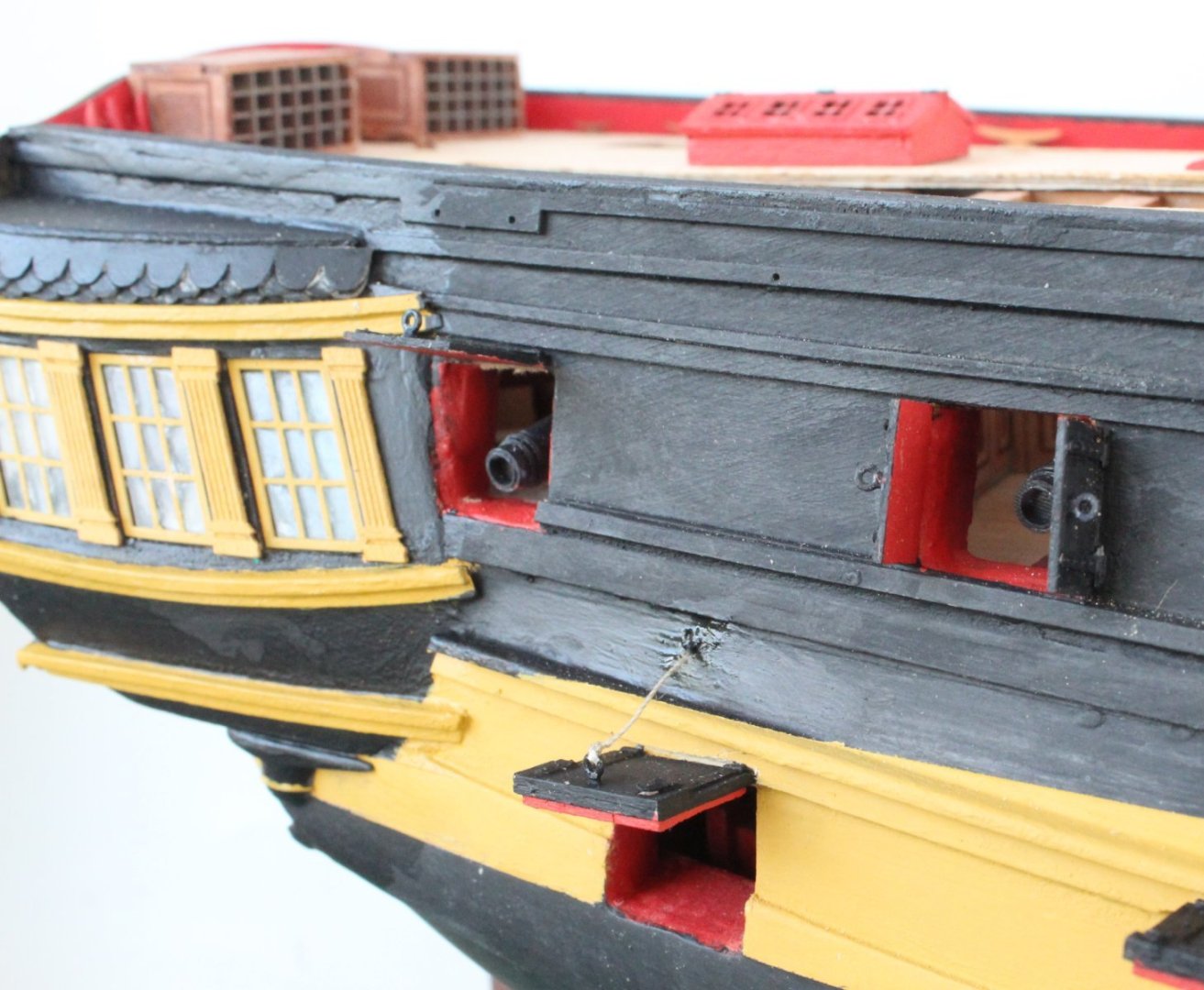
The stern gun port lids were test fitted. One gun port lid looks wonky in the first photo (blue arrow), not sure why.
The installation is now complete. I did touch up some of the black paint which was still wet when I took the following photos.
The top left hand gun port lid has not been glued in place as I will remove it whilst I add the small channel, strops and chain links which is located above it.

- BLACK VIKING, davyboy, mugje and 8 others
-
11
-
-
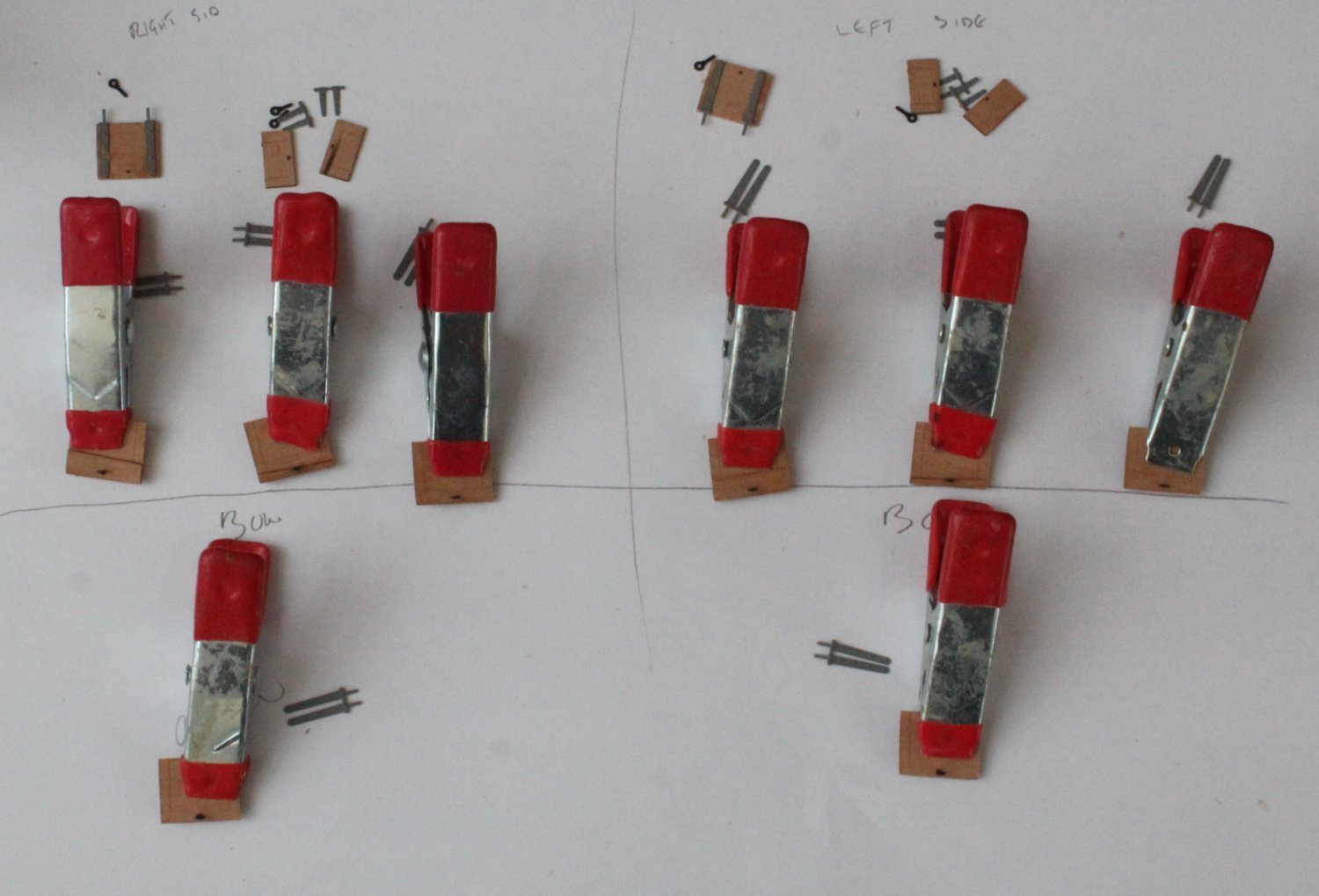
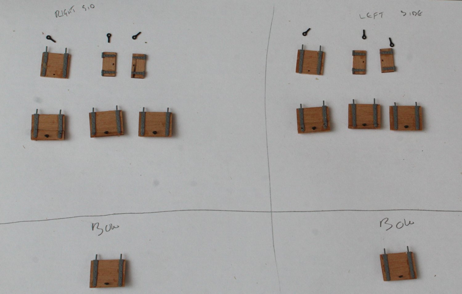
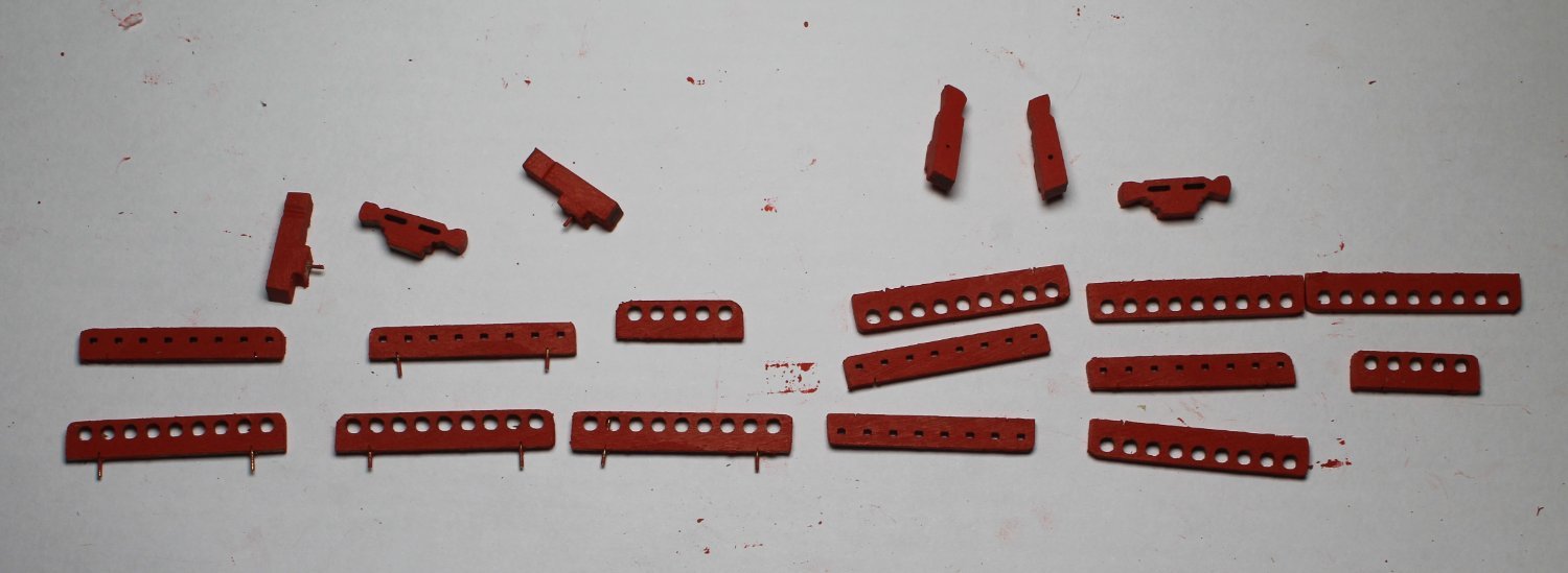
Gun Port Lid Assembly
Today I started work on the gun port lids. There are 6 gun ports per side which will have lids.
The first task was to collect all the various parts, which was a mixture of wooden and PE parts. The various lids were placed in their respective hull positions to ensure I built them up correctly.
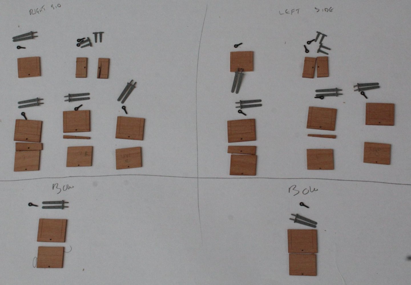
Using the eyebolts as an alignment guide the various wooden parts were glued and clamped.

The next task was to add the hinges.
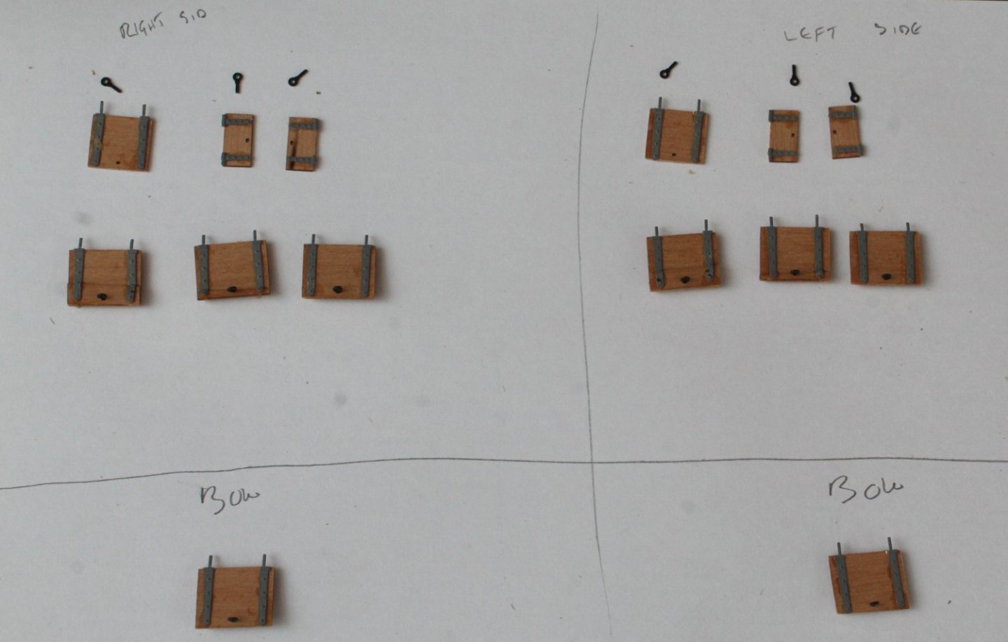
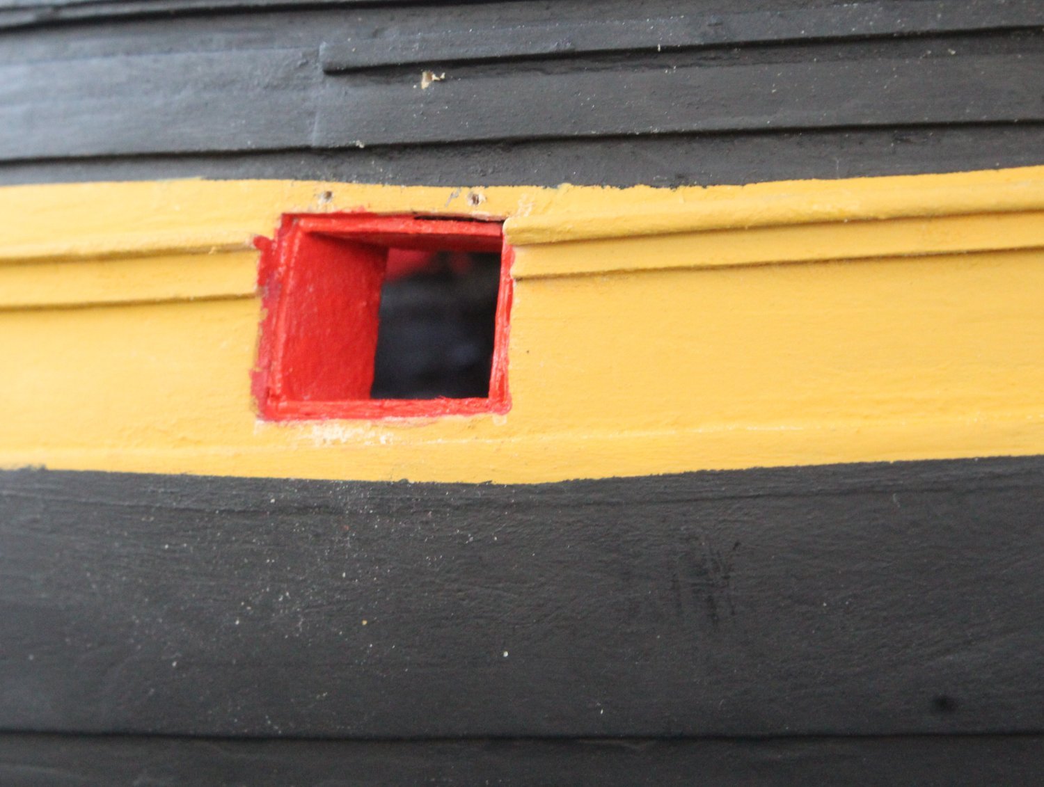
Once the eyebolts were glued in place the gun port lids were painted, red for the inner surface and black for the outer surface.
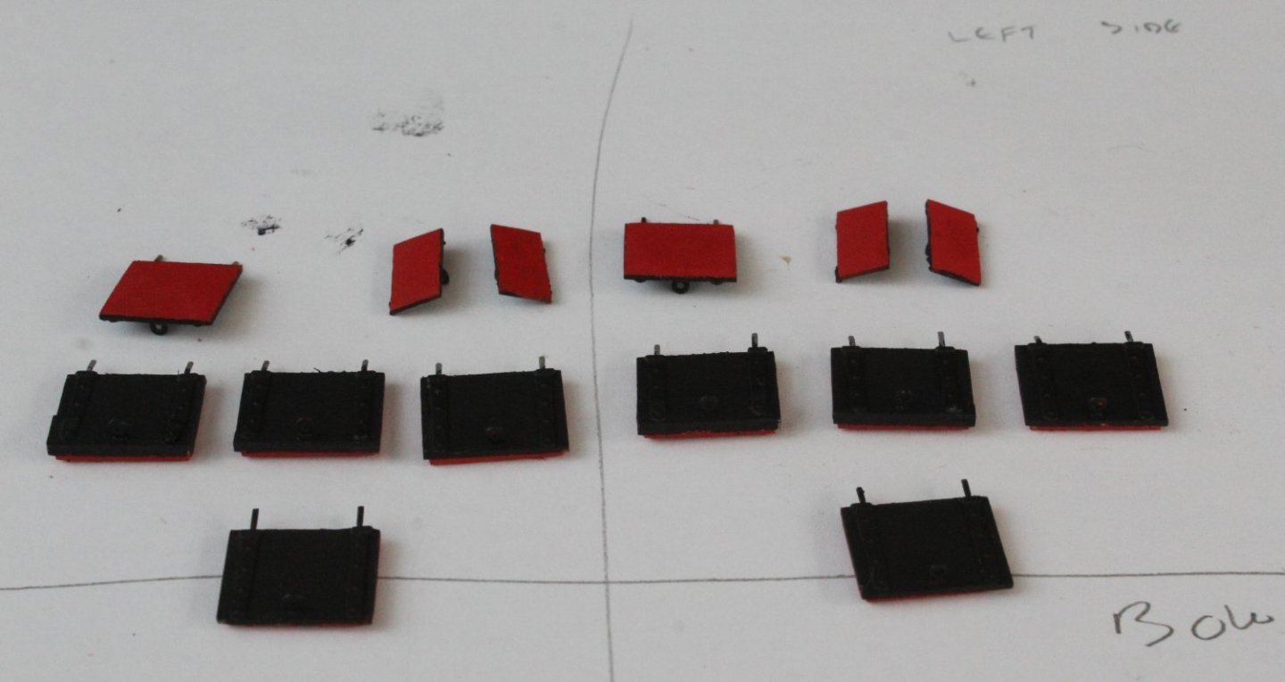
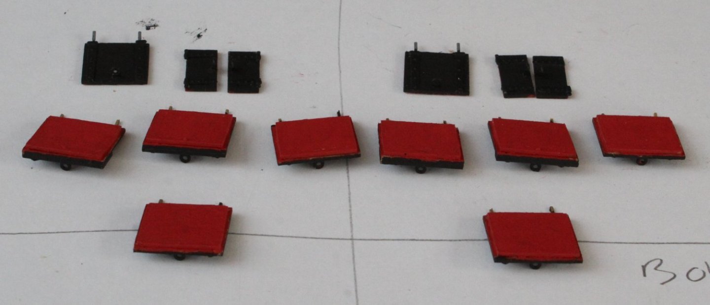
The next task will be to fit the lids to their respective gun ports. Starting with the right-hand side bow gun port I drilled the holes, in the hull, for the hinges and the thread. I took a couple of pictures with the gun port lid dry fitted. I noted that actual gun port opening was wider than the gun port lid and I then realised that I did not add the kit supplied gun port linings so I will need to add them.

- ECK, davyboy, KARAVOKIRIS and 8 others
-
11
-
19 minutes ago, Kevin said:
looks fantastic
Thank you Kevin. There are a few things I could have done better but overall I am pleased with my Indy build.
- chris watton, Kevin, CiscoH and 2 others
-
5
-
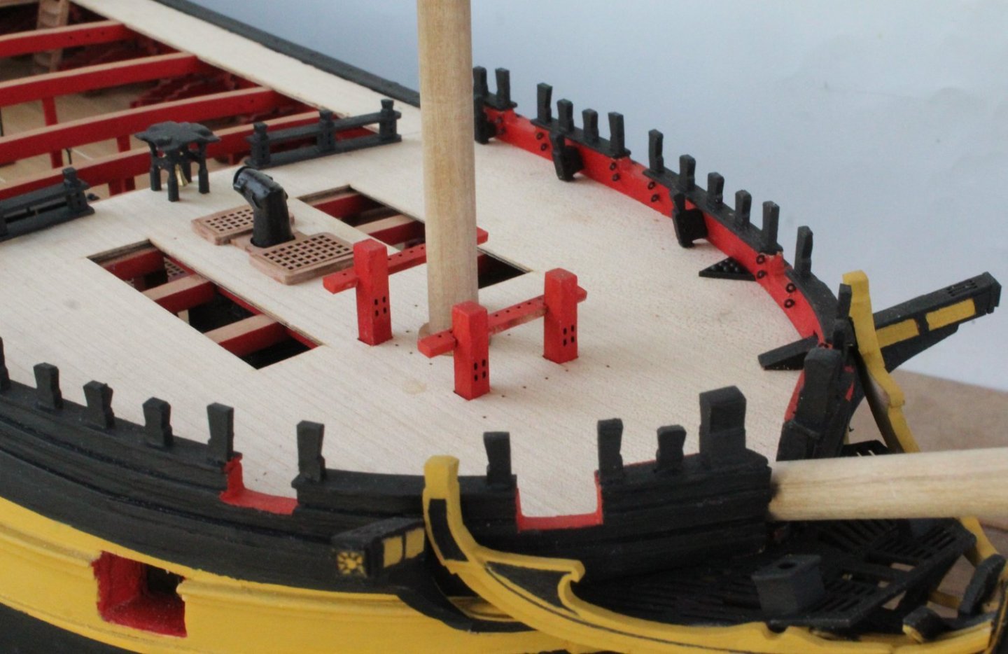
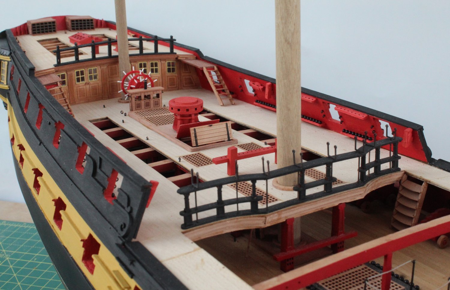
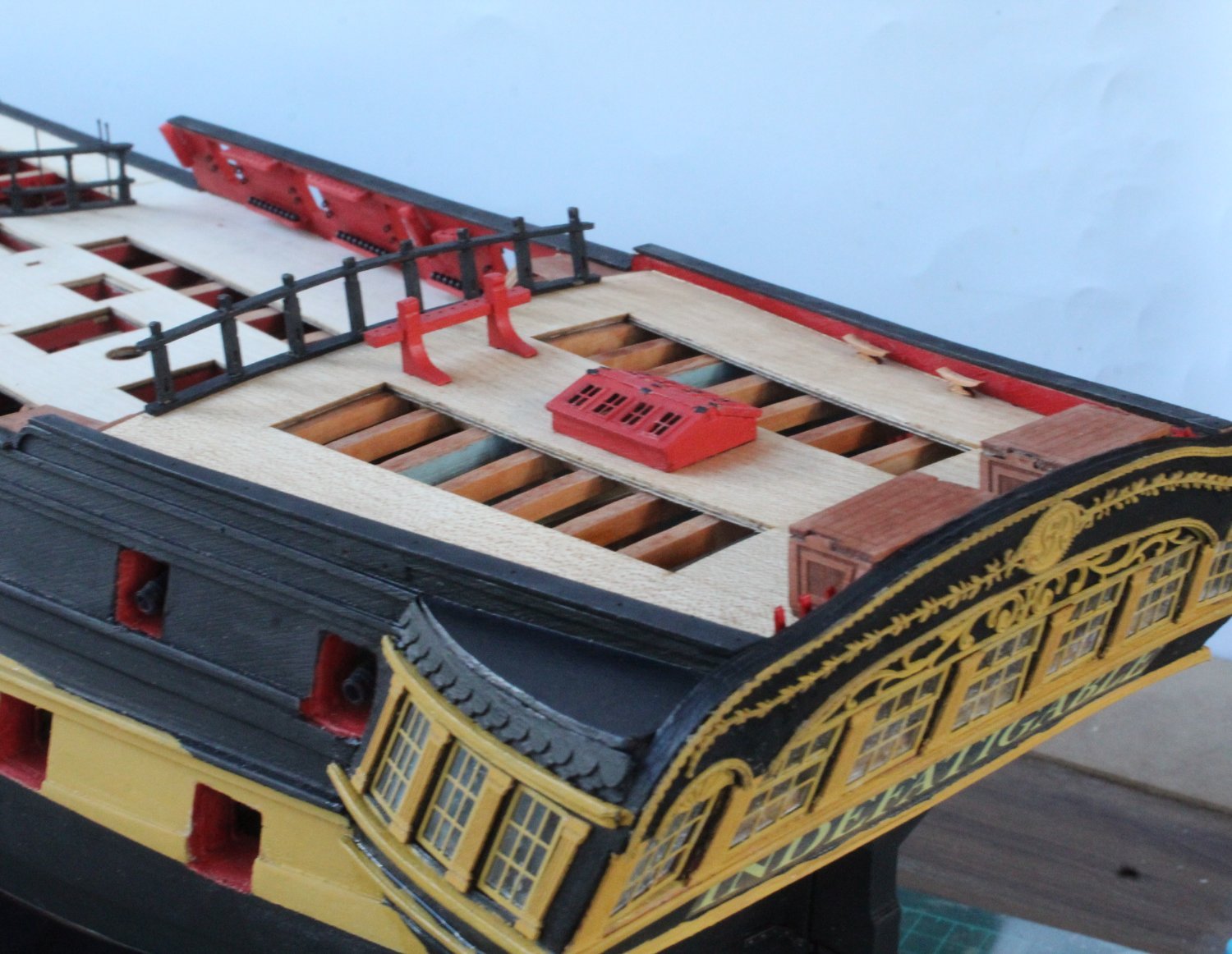
Deck Work Completed
I had a really good day in the shipyard and made much more progress than I was expecting.
I have now completed adding all the various deck items.
Forecastle Photos
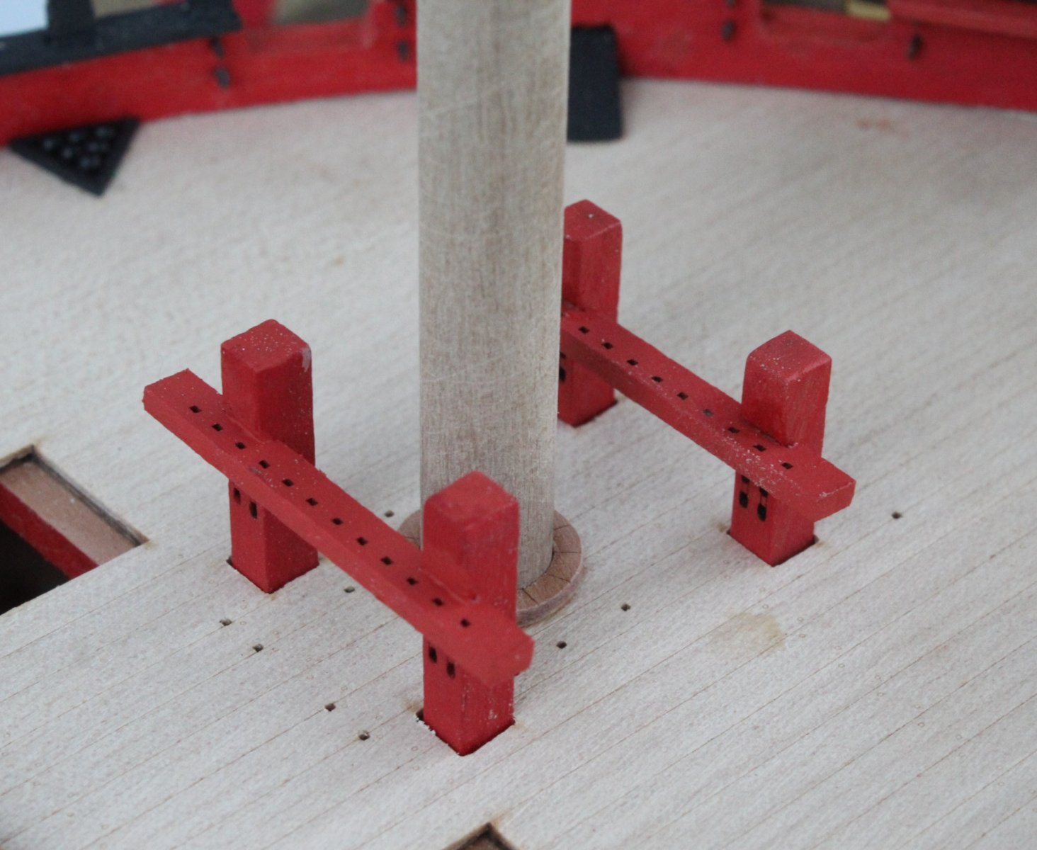
Bitts, after the forward belaying rack was reposition. The foremast ring has also been added with the foremast test fitted.

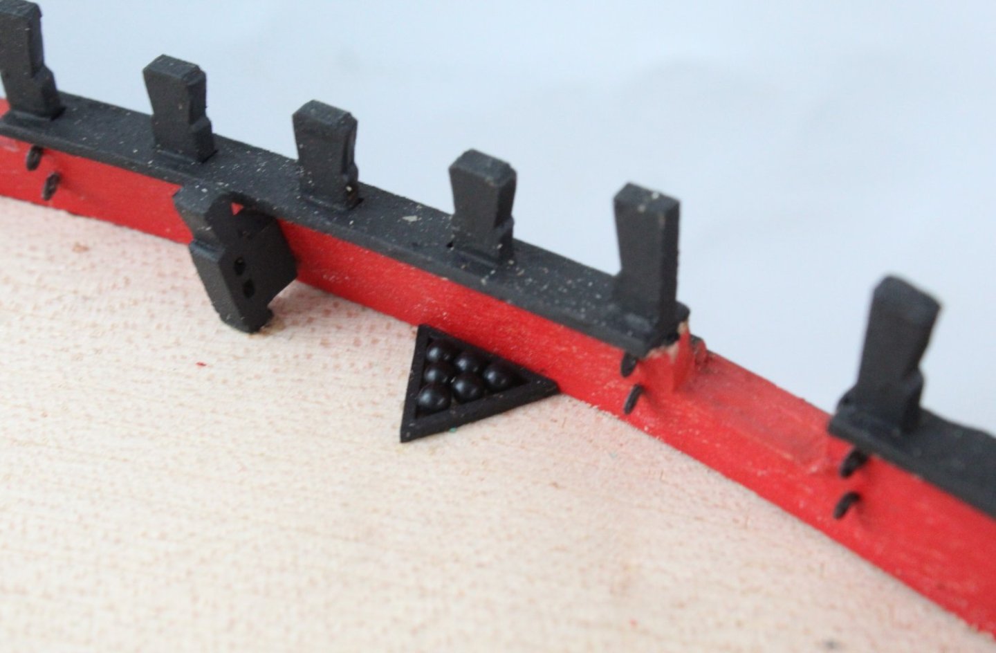
Shot garlands
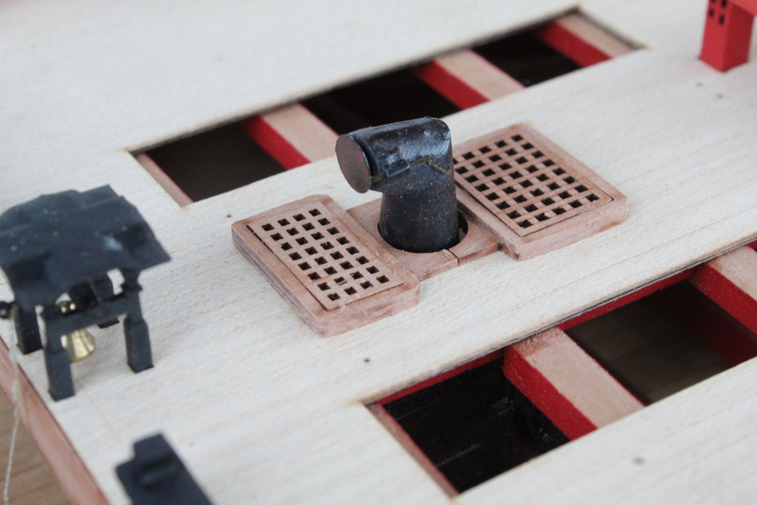
Stove and hatch covers

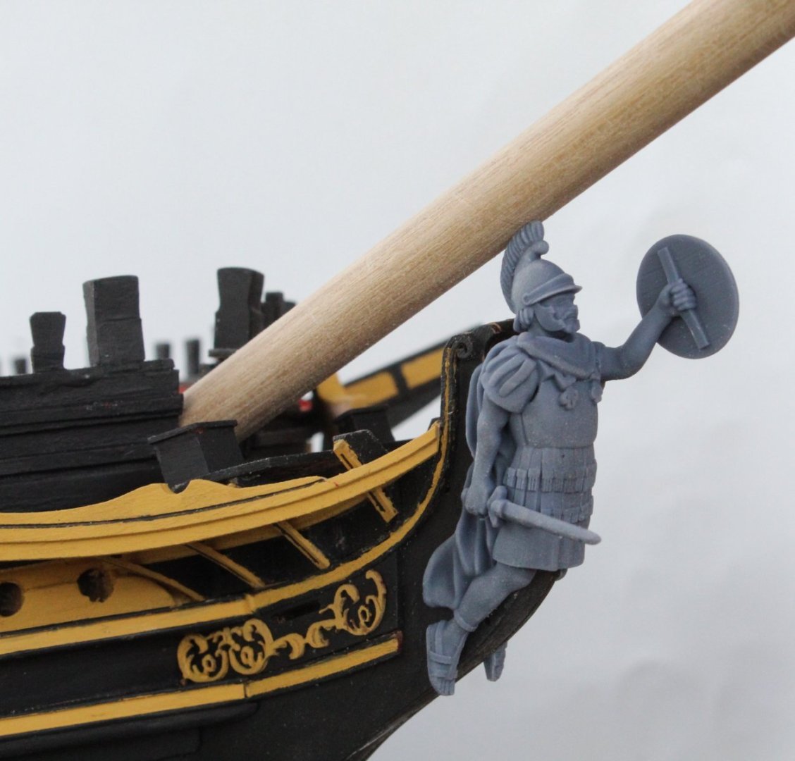
Figurehead test fit. I'm not sure why the figurehead's toes away below the stem post and will require a little bit of detective work.
Forecastle Deck
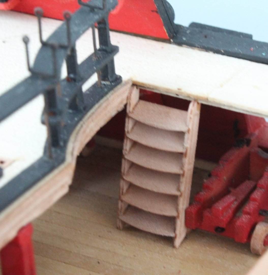
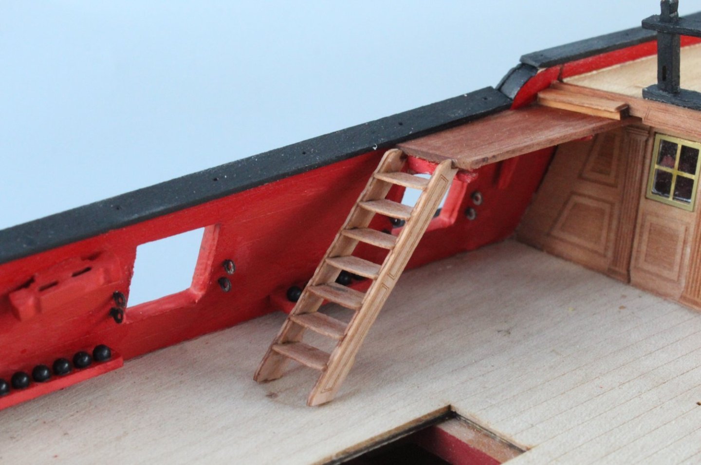
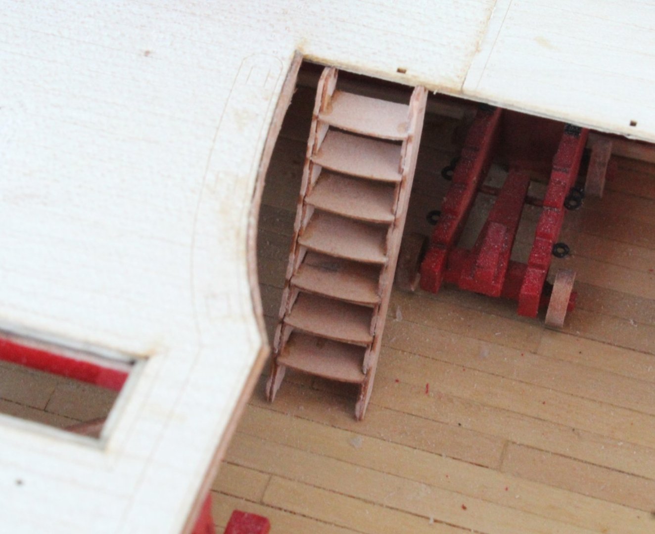
Gangway Photo
A nicely out of focus photo. It took several attempt to fit these ladders and this was the best fit I could achieve.
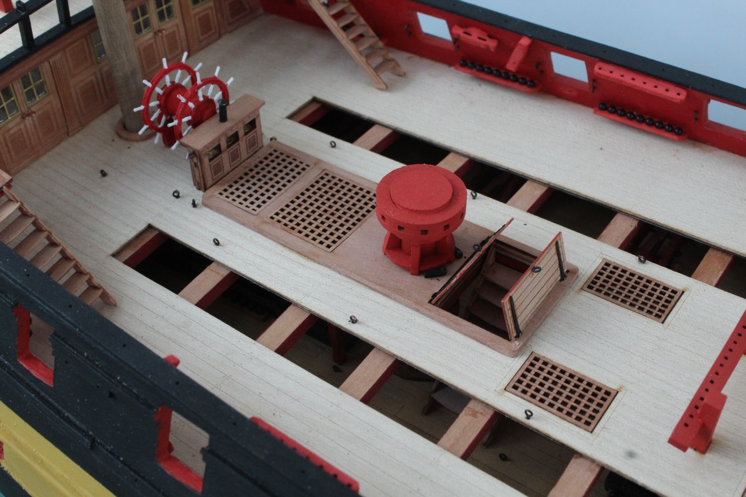
Quarterdeck Photos
Main mast ring, bitts and hatch covers
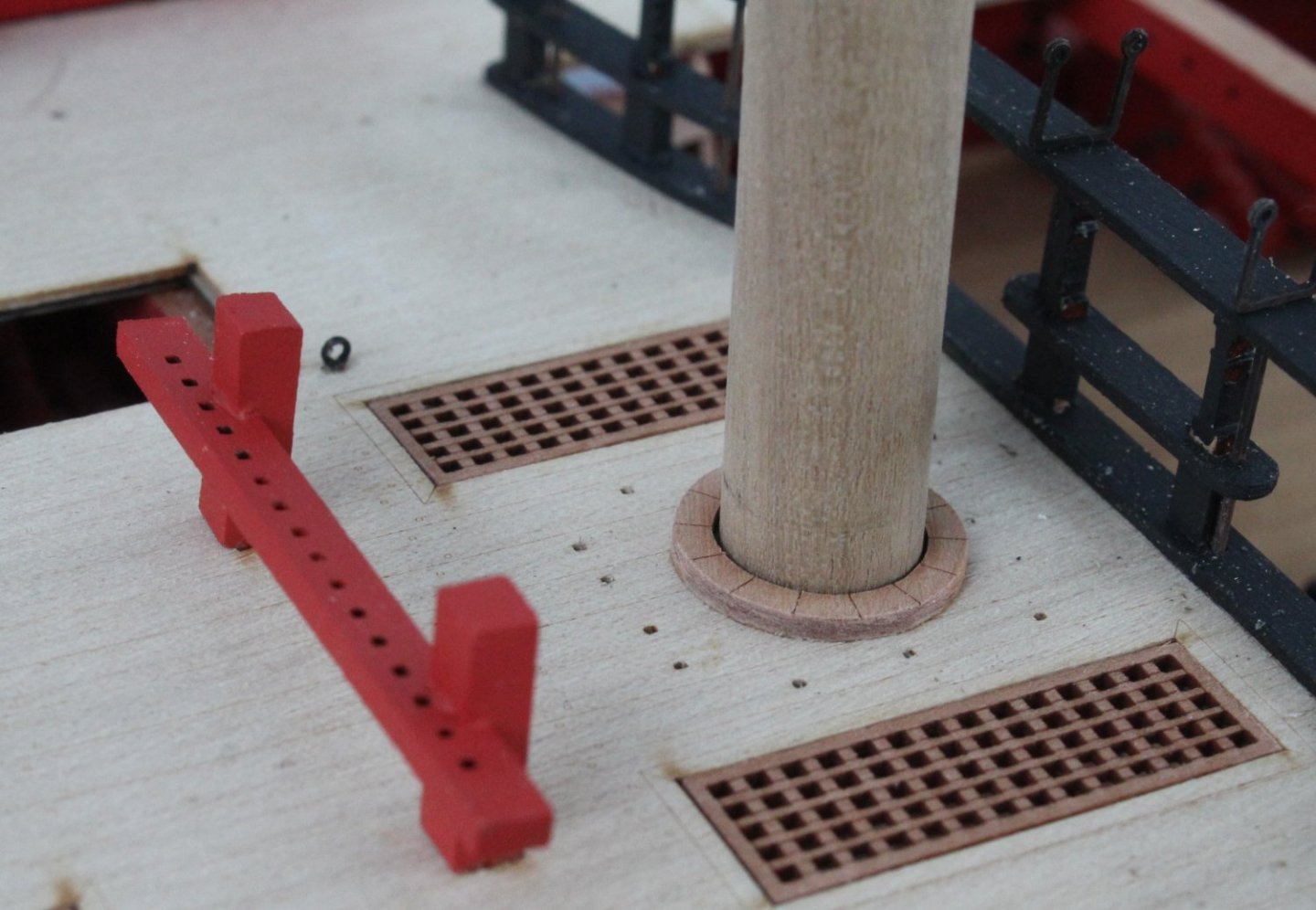
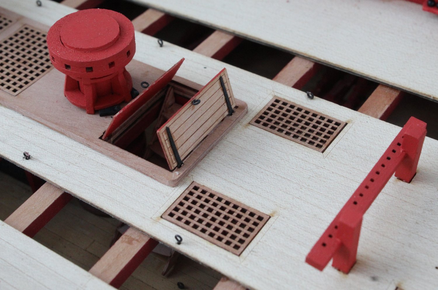
Hinged hatch covers and capstan

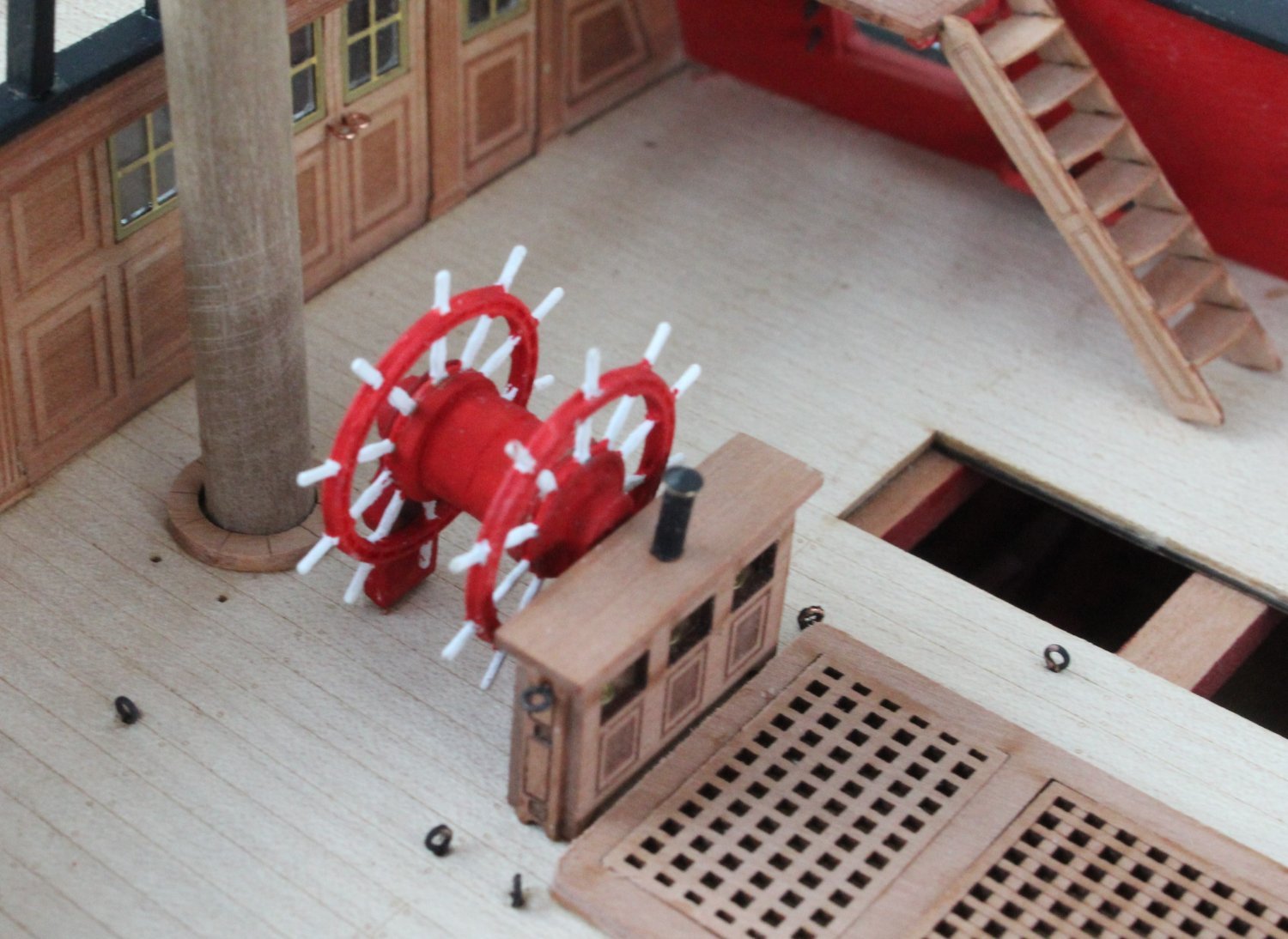
Binnacle, ships wheel and mizzen mast ring. I might add some rigging for the binnacle.


Quarterdeck

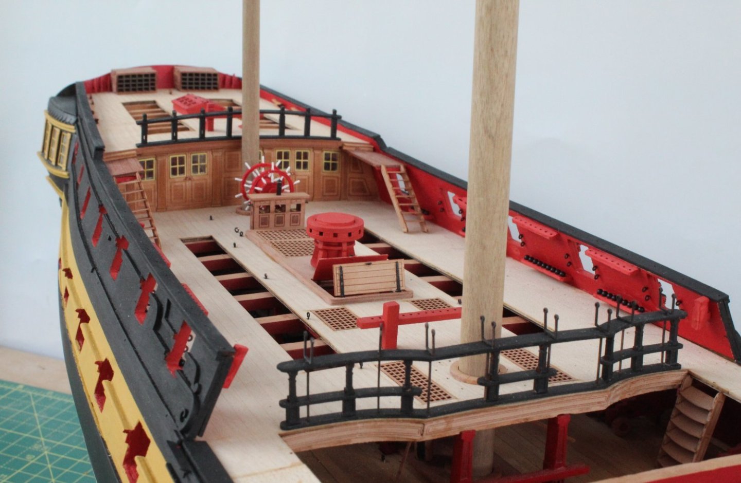
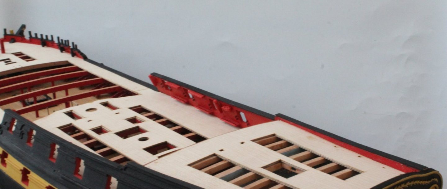
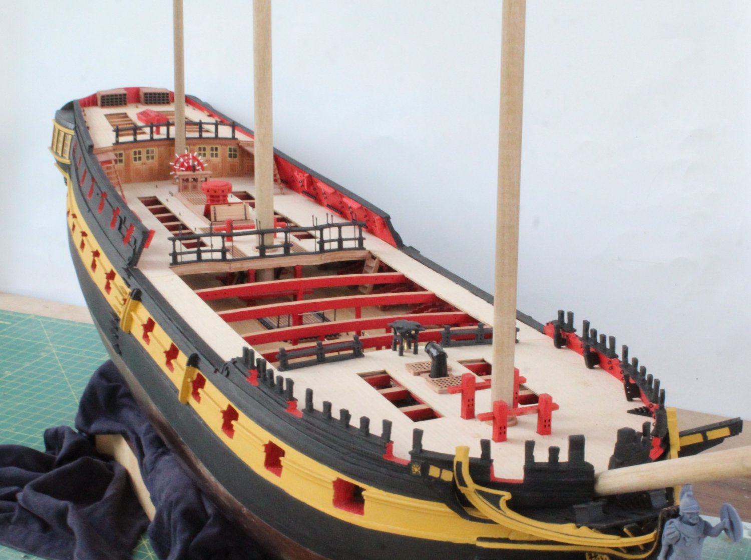
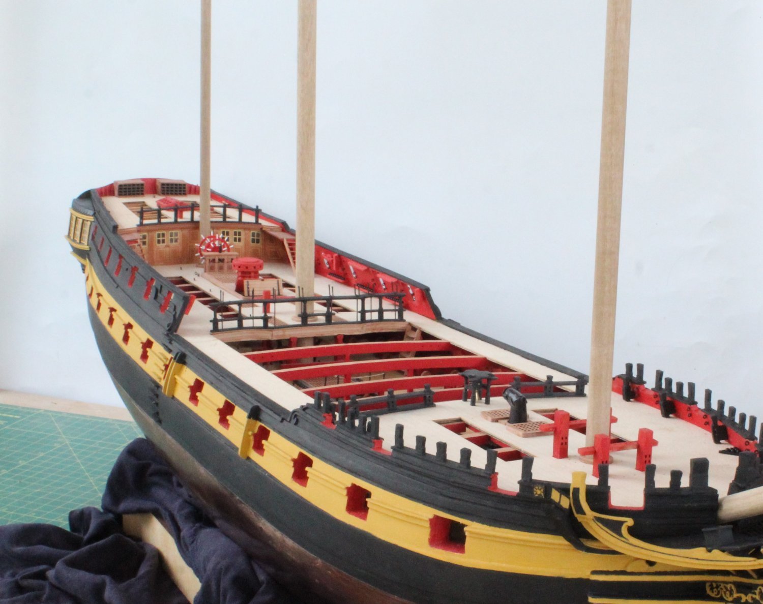
Indy Build Status Photo's

The next task will be to fit the channels and gun port lids.
-
Forecastle and Poop Deck Work
It has been a bits and pieces sort of day today. I started by adding the two belay pin racks to the forecastle bitts. I noticed the belay rack(top one) should have been installed the other way around. Thankfully it was an easy job to correct.
Next I assembled and fitted the belfry to the forecastle

I then turned my attention to the poop deck and added the cleats, flag lockers, skylight and bitts. I normally add the deck eyebolts during the rigging phase as sometimes I find it beneficial to add the rigging to some of the eyebolts off deck.
It is an optical illusion that the poop deck rails appear to be leaning forward in the attached photos.

The final task was to add the steps and small gangway decks (left and right) up to the poop deck.
I will continue to add more deck items over the next few days. I am leaving adding the various channels as one of the last tasks before I start making the masts and yards.
- mtaylor, Ryland Craze, ECK and 5 others
-
8
-
5 minutes ago, Thukydides said:
Great progress Glenn, it is looking good.
Thank you, I hope to start making the masts in a few weeks time.
- mtaylor and Thukydides
-
2
-
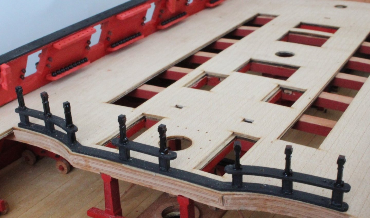
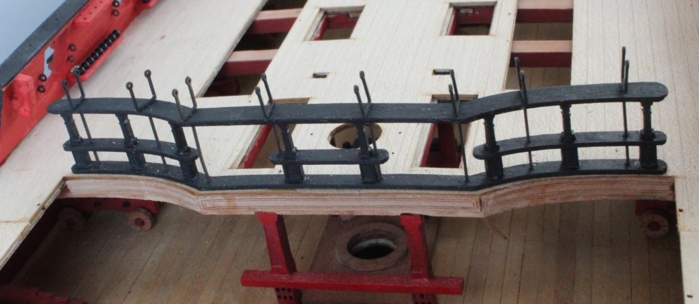
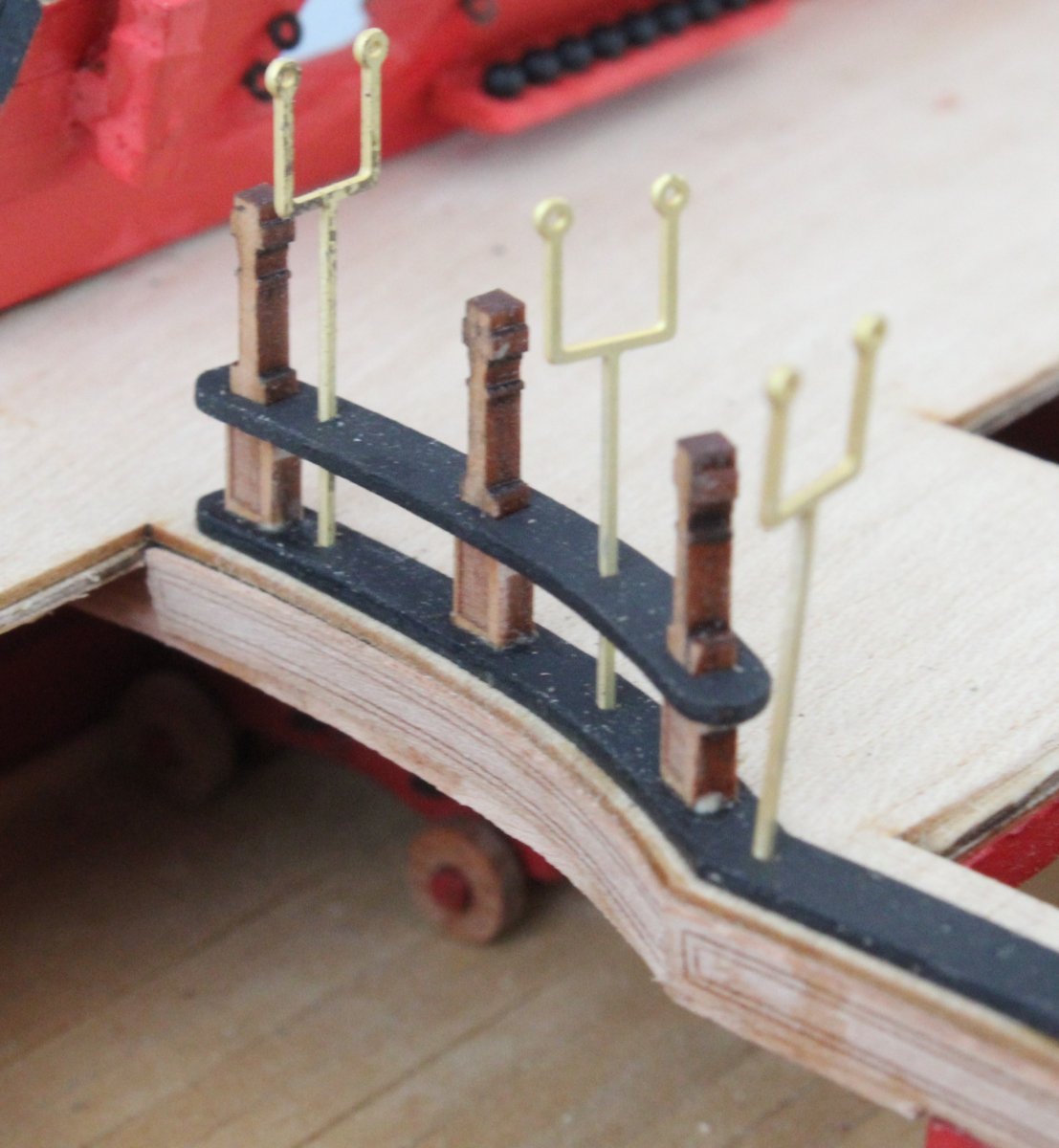
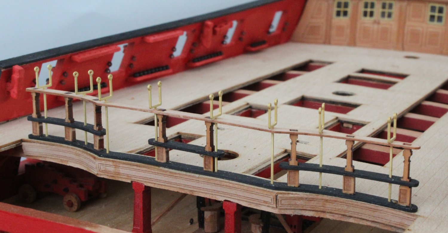
Quarterdeck Barricade Rails and Stanchions
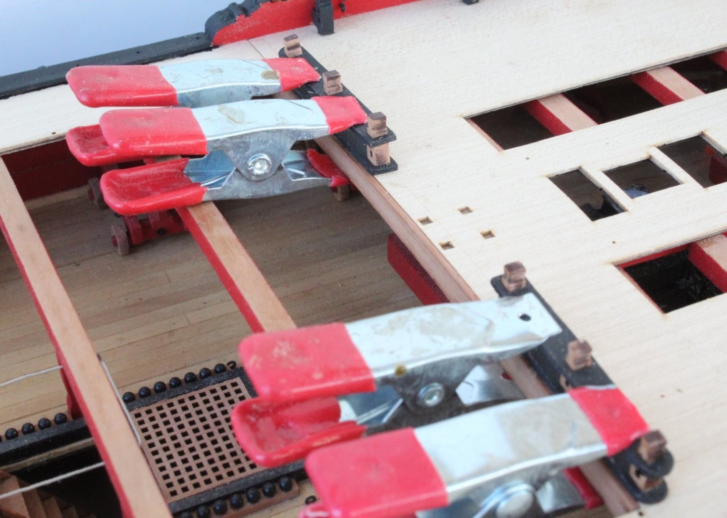
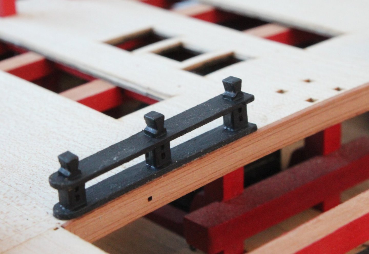
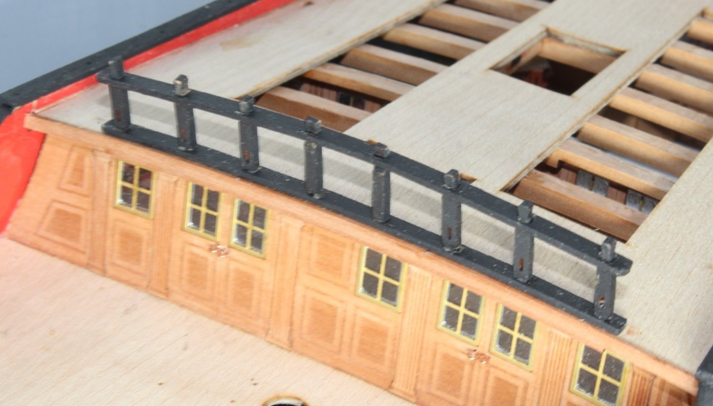
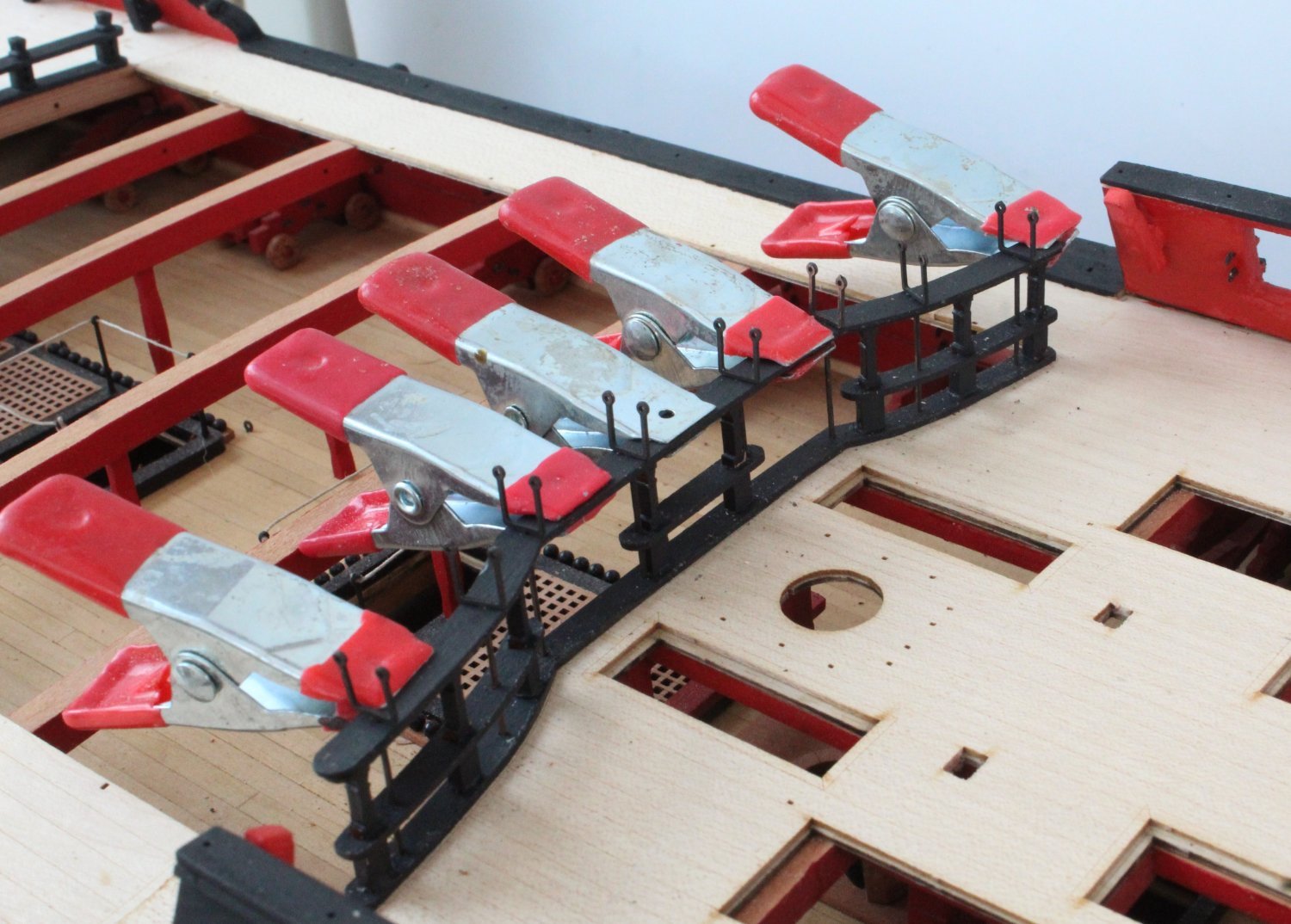
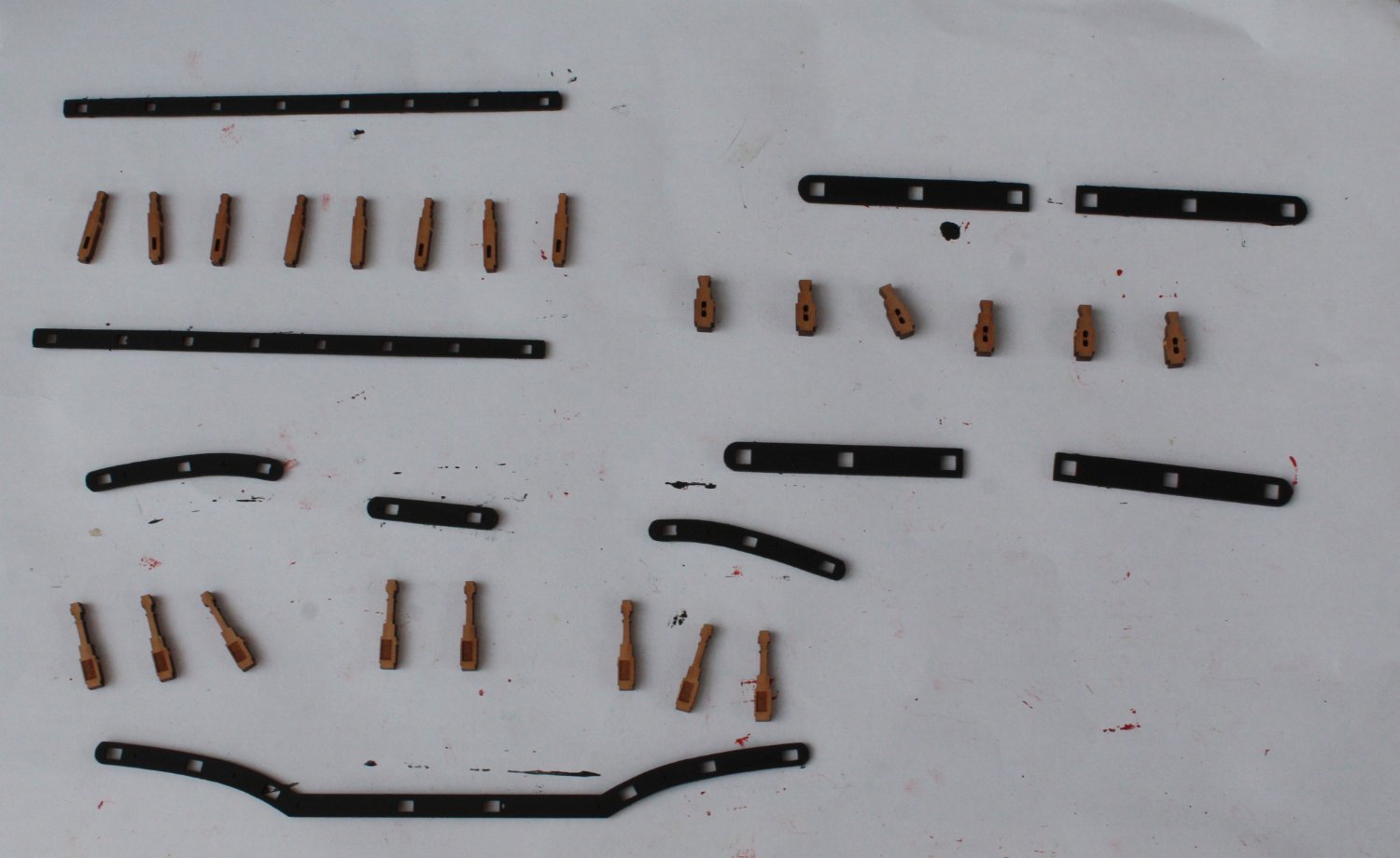
On my return from Manchester I was able to get a couple of hours work in the shipyard and I managed to completed adding the Quarterdeck Barricade Rails and Stanchions.
I started the assembly process with gluing the Quarterdeck Barricade Stanchions in place on the lower rail. I used the hammock cranes and quarterdeck barricade mid rails as guides to ensure the stanchions were in the right position.

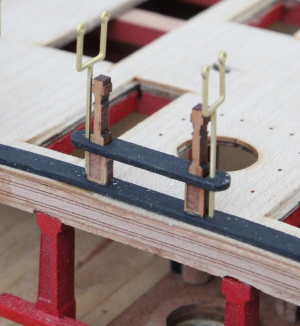
Next I checked the fit of the upper rail (lower). Everything was looking good.

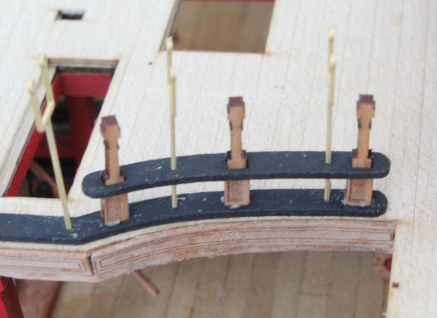
It was then time to paint the Quarterdeck Barricade Stanchions black and to then glue the mid rails in place.
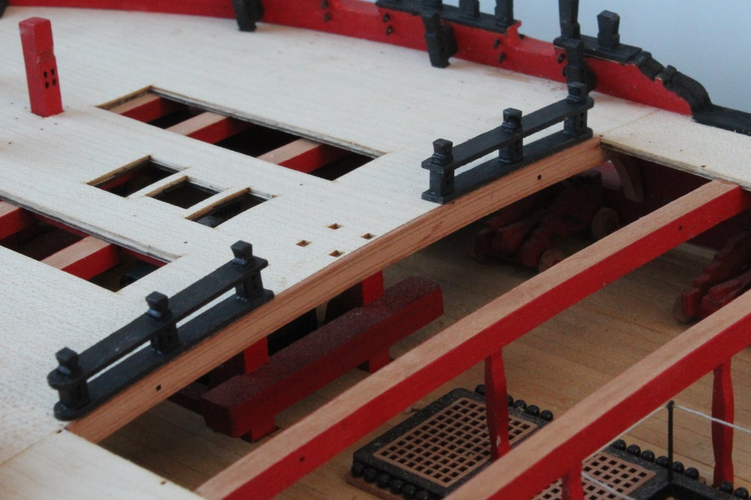
The upper (lower) rail was then added, noting the hammock cranes have now been chemically blackened.
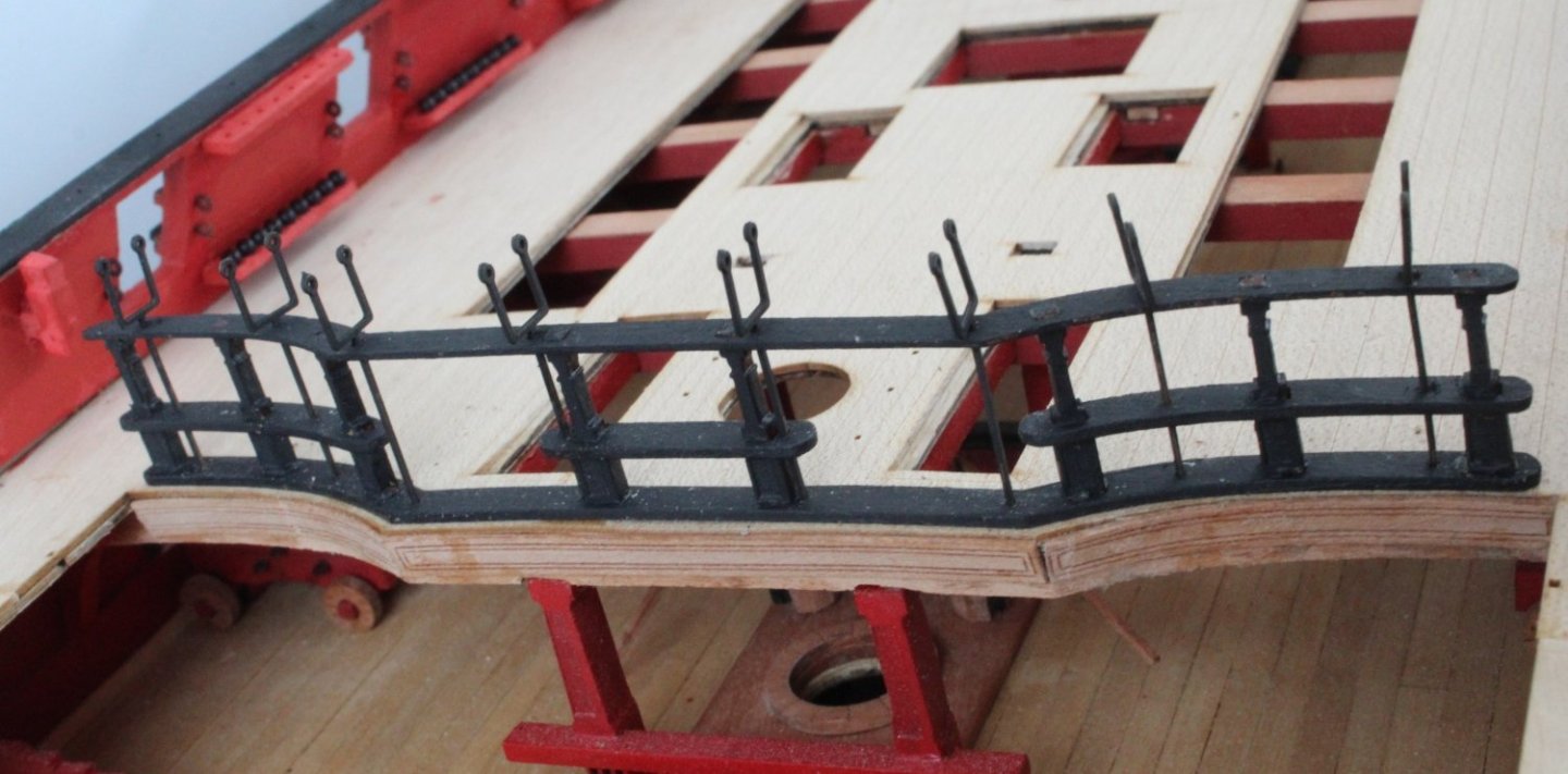
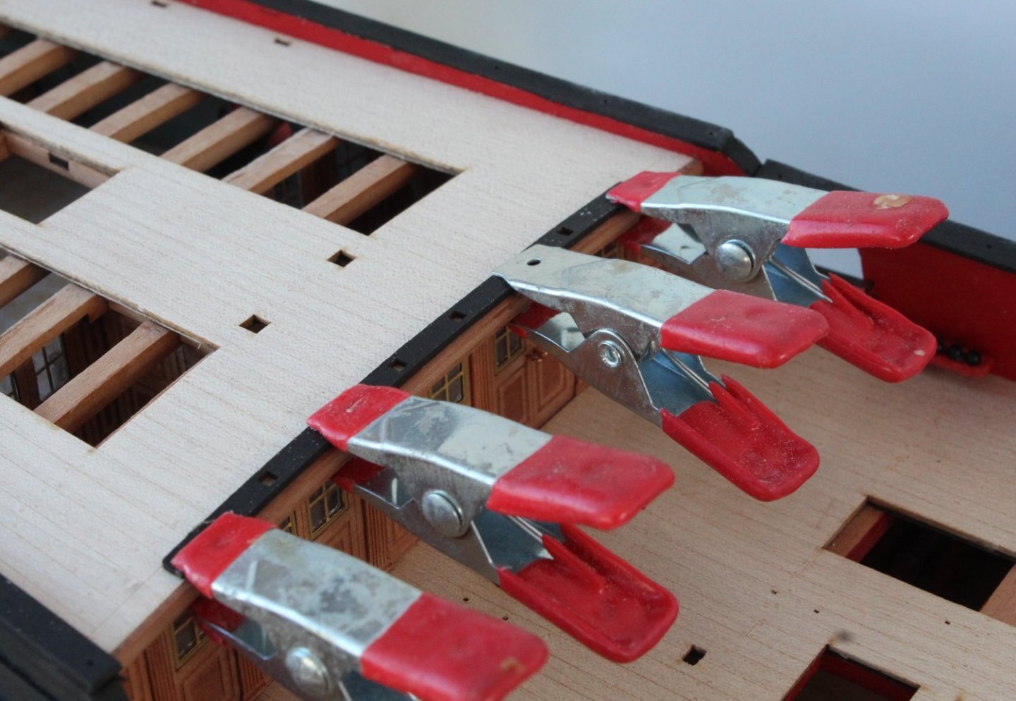
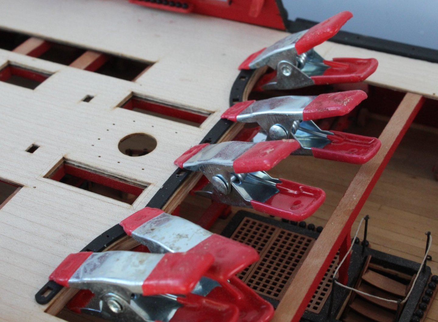
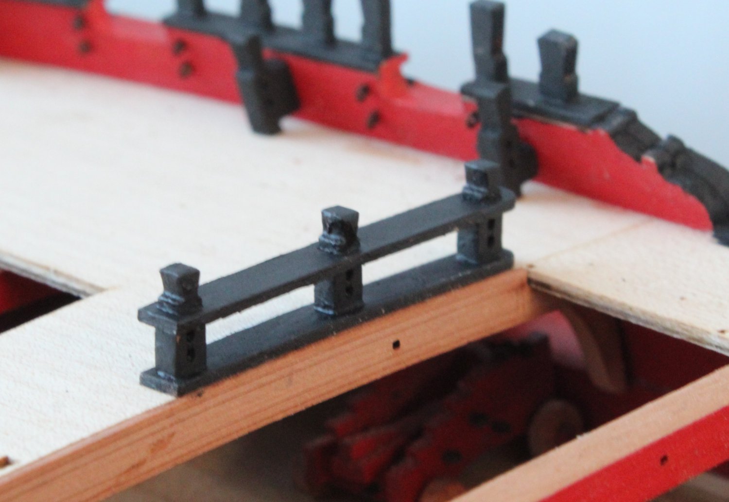
The final task was to add the upper rail, which was clamped.

The completed assembly looks good. The hammock cranes are only dry fitted for the time being, there were only used to ensure all the rails were correctly aligned during the assembly.
-
Deck Decorations
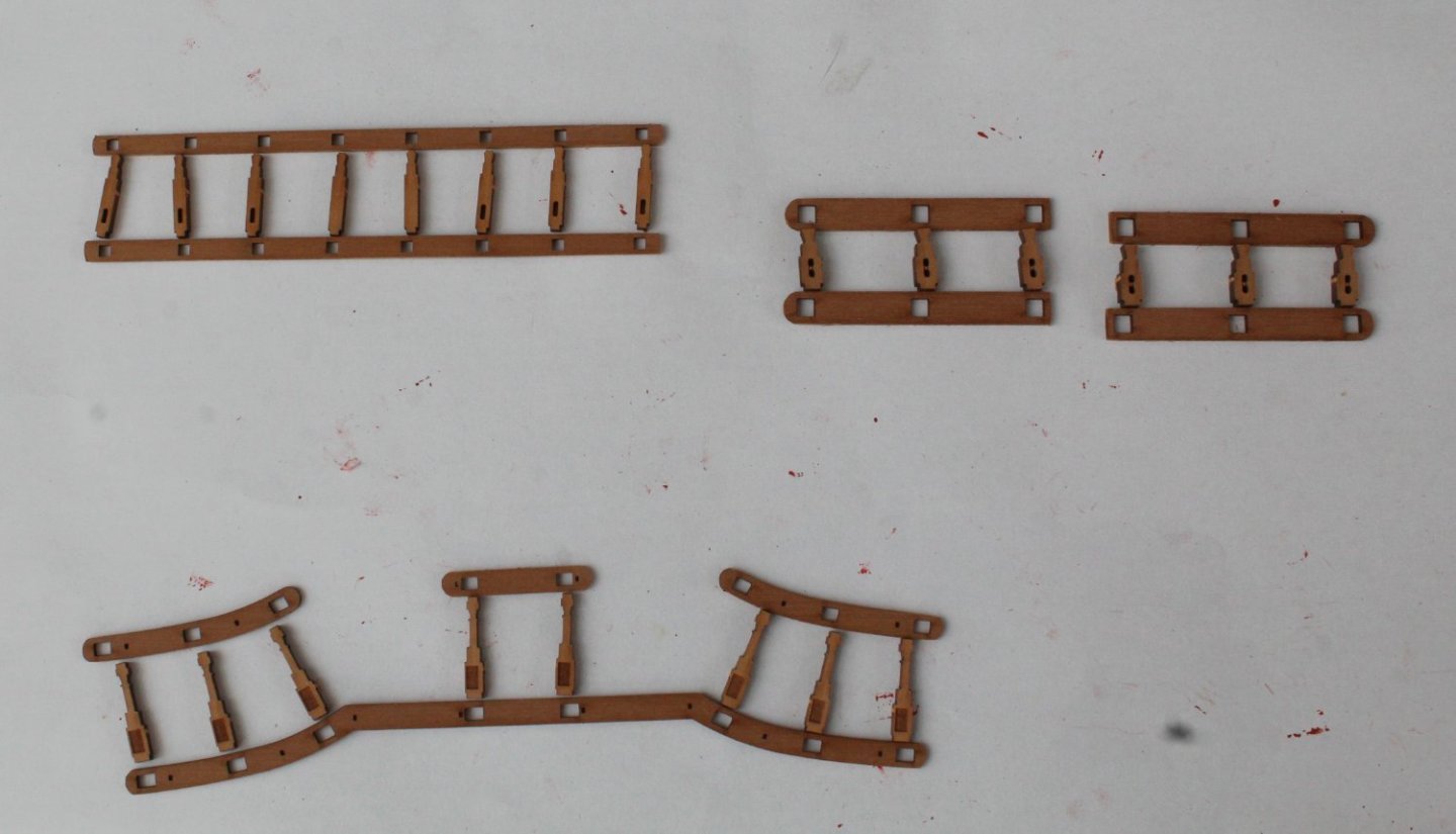
I made the 5 remaining ladders, 2 for access to poop deck, 2 for access to gangways and one for the quarterdeck hatch.
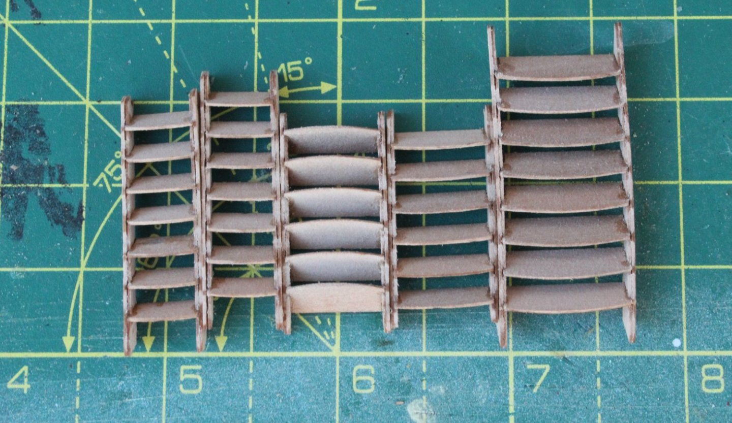
I did a quick check of one of the walkway ladders, seems to be a good fit.
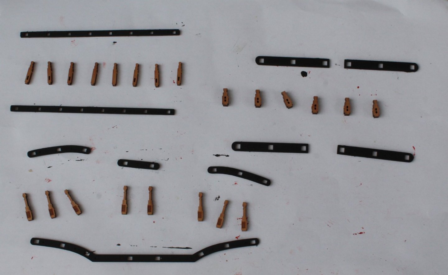
The various deck decoration parts were gathered.
The first task was to paint the parts black.
Next the base parts were glued to the decks
The forecastle deck parts were completed.


Next I did the poop deck, due to low light I used a flash light for the next photo, not a very good quality photo.
I'm off to Manchester for the weekend (to visit new grandson) so no time will be spent in the shipyard to add the quarterdeck decorations.
- Thukydides, mtaylor, CiscoH and 8 others
-
11
-
Quarterdeck Inner Bulwarks
There are a few items to be added to the quarterdeck inner bulwarks, such as the cannon eyebolts and shot / belaying pin racks.
The eyebolts were chemically blackened and fitted first. With these in place the remaining items were test fitted. Pins were added to the shot / belaying pin racks, using the guidelines provided. The various items were then test fitted.

The various parts were then painted red.

I also painted the gunwales black before the various painted parts were added to the inner bulwarks.

The final task was to add the cannon balls to the shot racks.
- Ryland Craze, James H, Thukydides and 6 others
-
9


HMS Indefatigable 1794 by Glenn-UK - Vanguard Models - 1:64
in - Kit build logs for subjects built from 1751 - 1800
Posted · Edited by Glenn-UK
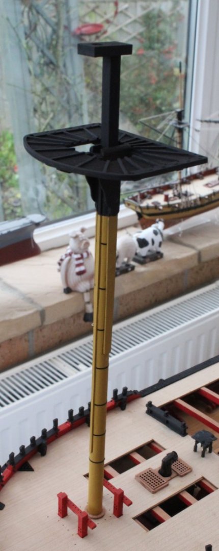
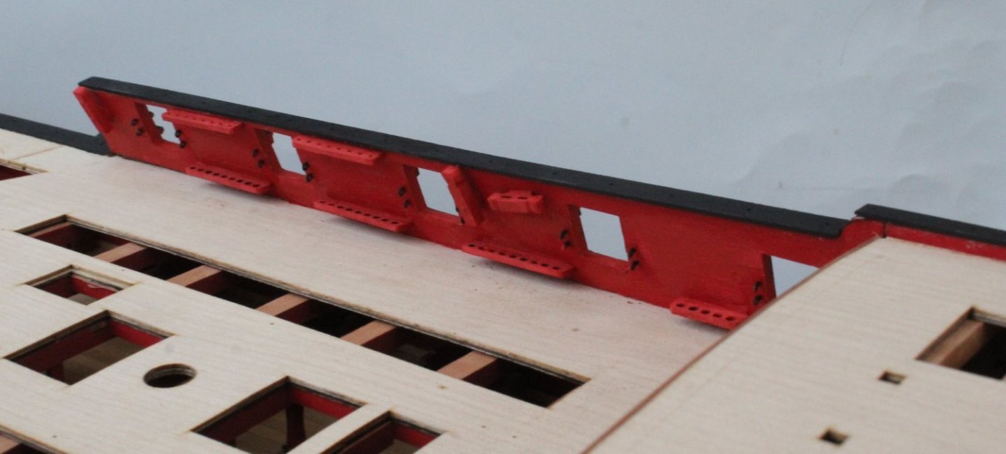
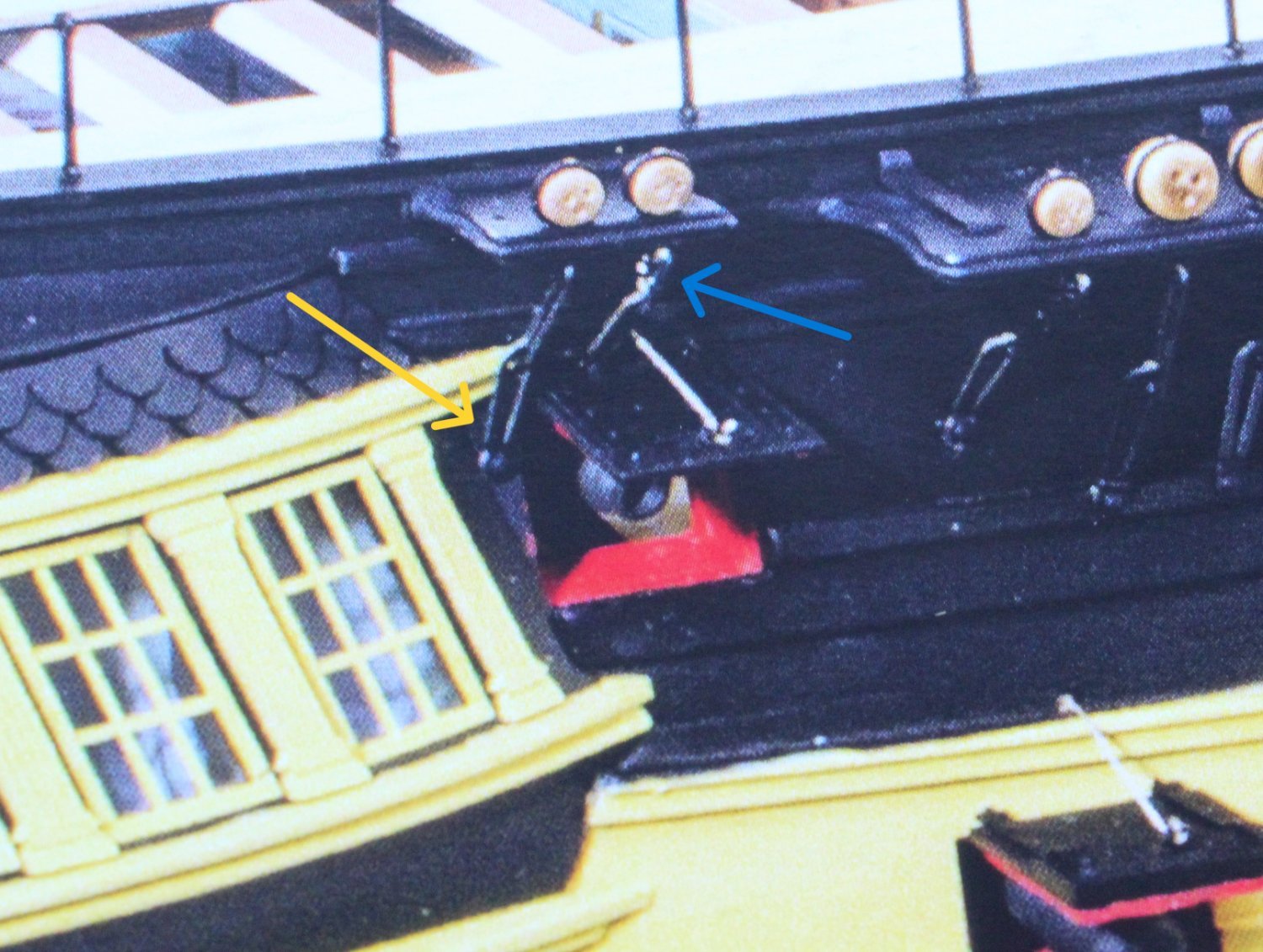
Lower Foremast Progress and Thoughts
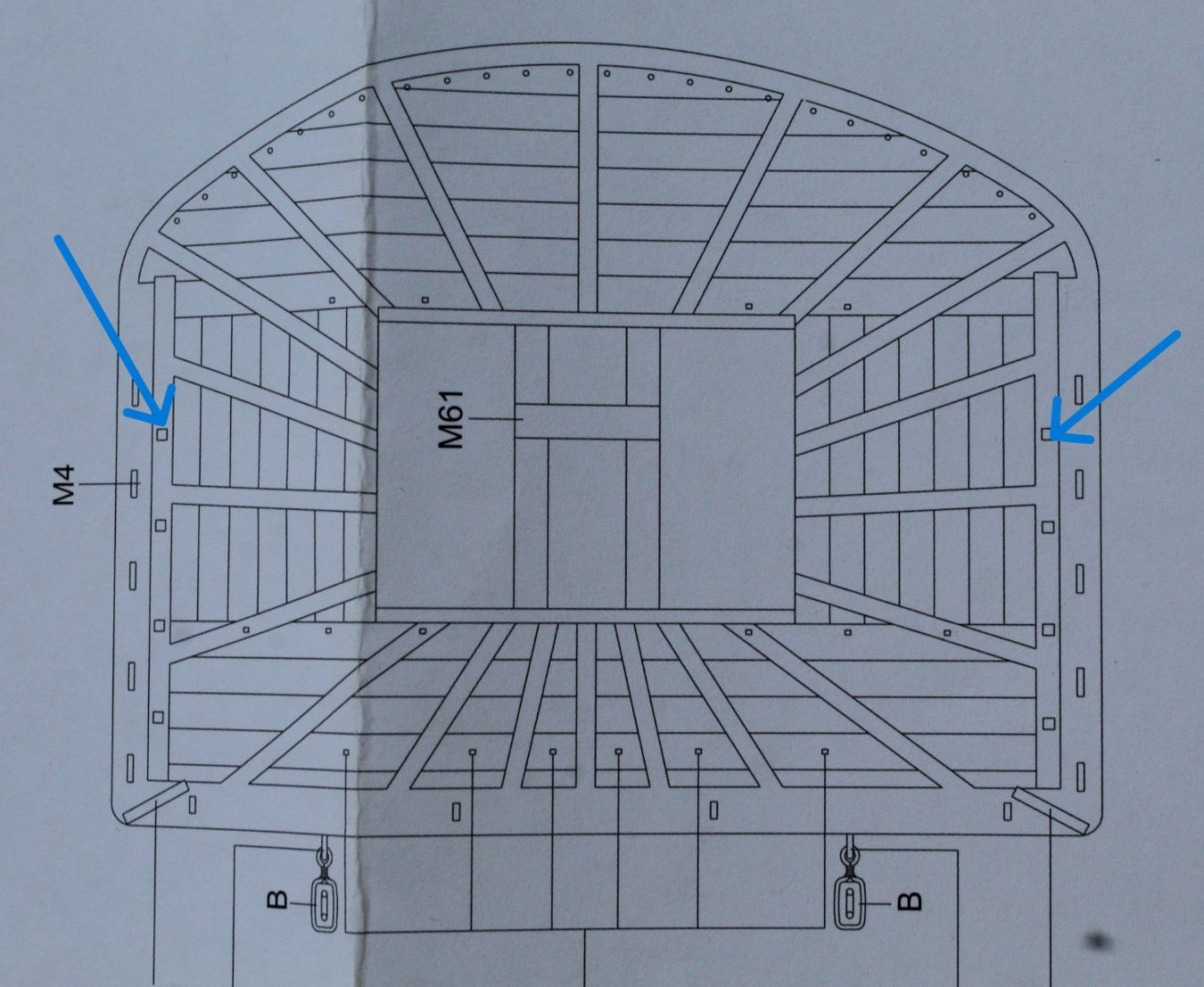
One area of the lower foremast assembly I have been contemplating is how best to secure the two yard lift blocks. These are 5mm single blocks, each with a thimble, and are wrapped around the foremast cap, as shown below (blue arrows).
This arrangement is also shown in C Nepean Longridge's excellent book The Anatomy of Nelson's Ships. There are two things to note when looking at the following photo. The first is the curved section fitted to the top of the mast cap, complete with grooves for the rigging as indicated by a blue arrow. This is a simple modification to the end cap and something I might consider adding. The second thing is how the the blocks are seized at the lower point of the block, as indicated by the the second blue arrow. They look like they are held in place by the main topsail bowlines and are also seized to the sling rigging.
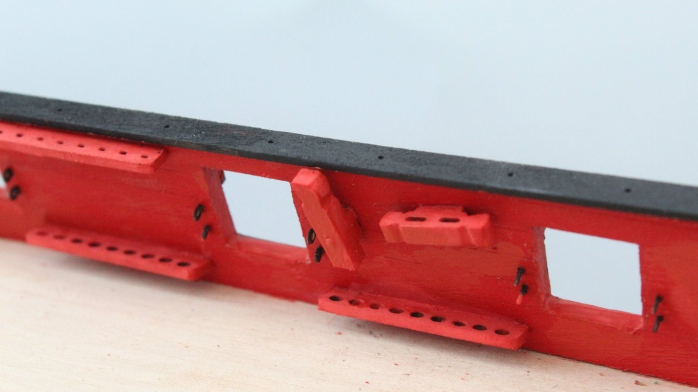
After a little bit of experimentation I determined the distance required between two block should be 110mm, without a curve top section added. I did add some seizing to hold the blocks in place once they had been wrapped around the end cap. However this should not be necessary when they are finally fitted as they will be held in place by the topsail bowline rigging which is wrapped around the mast. The yard slings, when fitted, will also help to keep these two blocks in place.
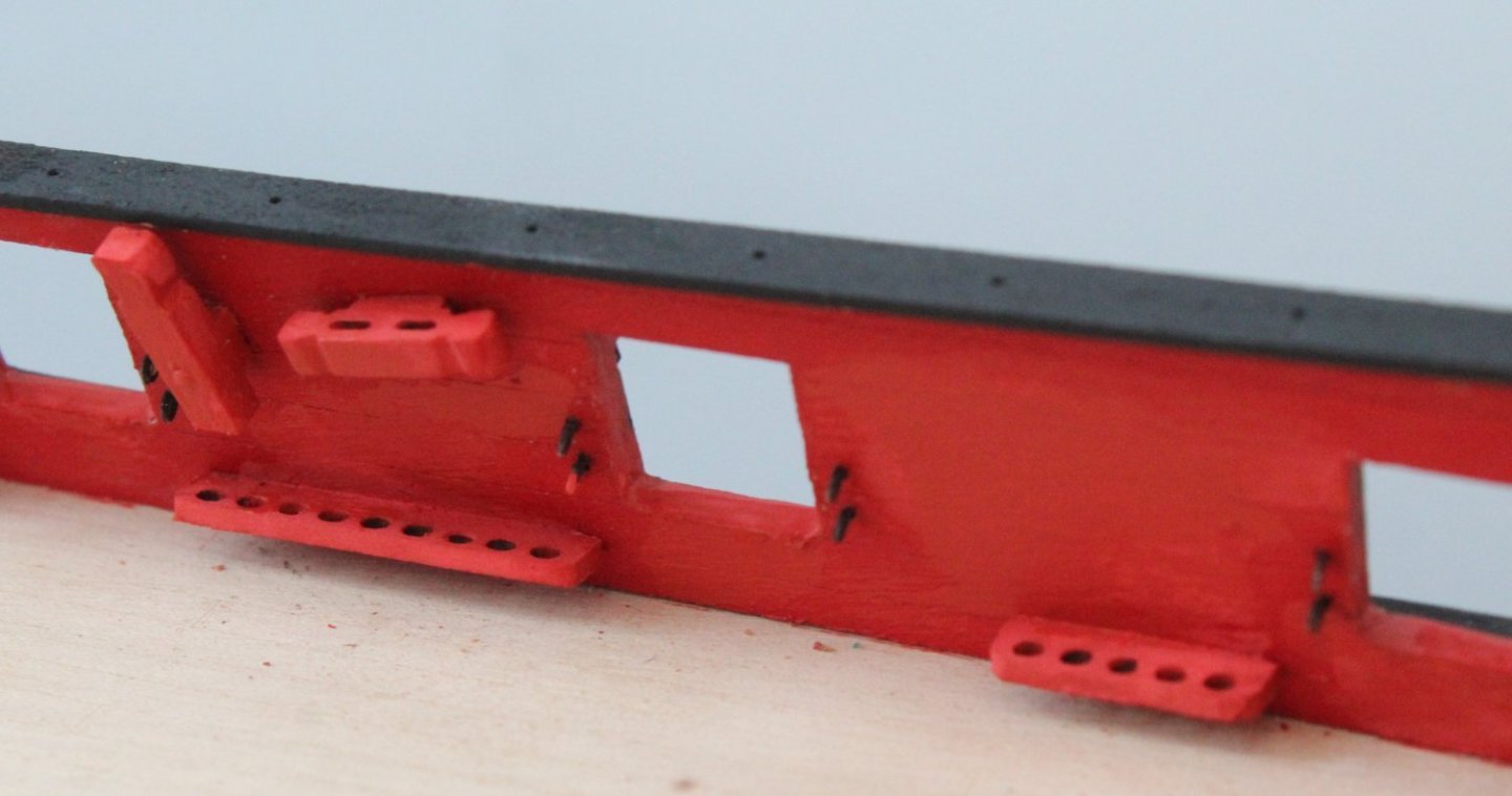
In my haste to test this method I forgot to add the thimbles to the ends of the 5mm blocks, so I will need to remake them. I also need to experiment with making and adding the 2 x topsail bowline 3mm blocks which wrap around the top of the foremast and will be positioned just below the mast cap as they will also hold the two yard blocks in place when fitted.
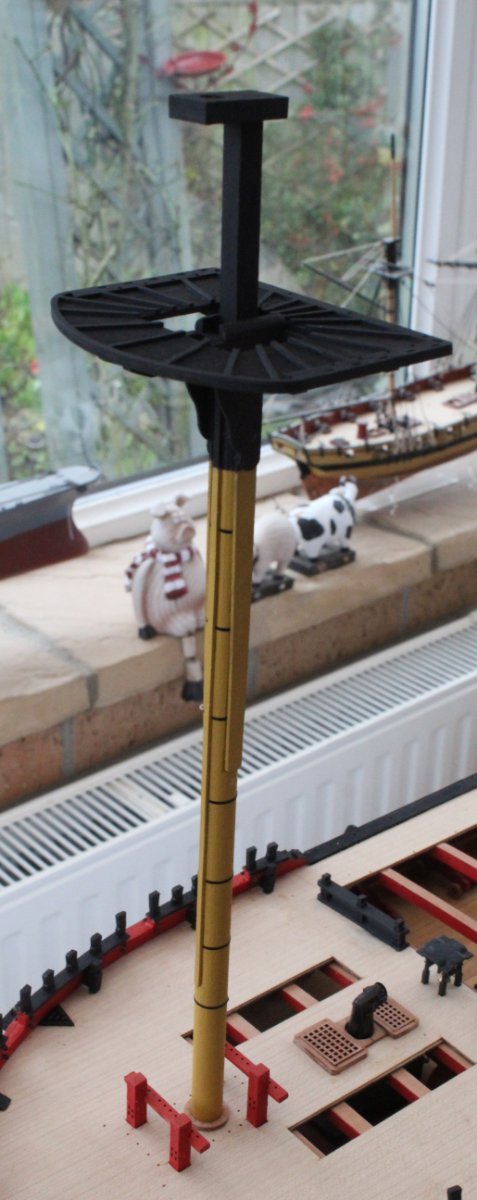
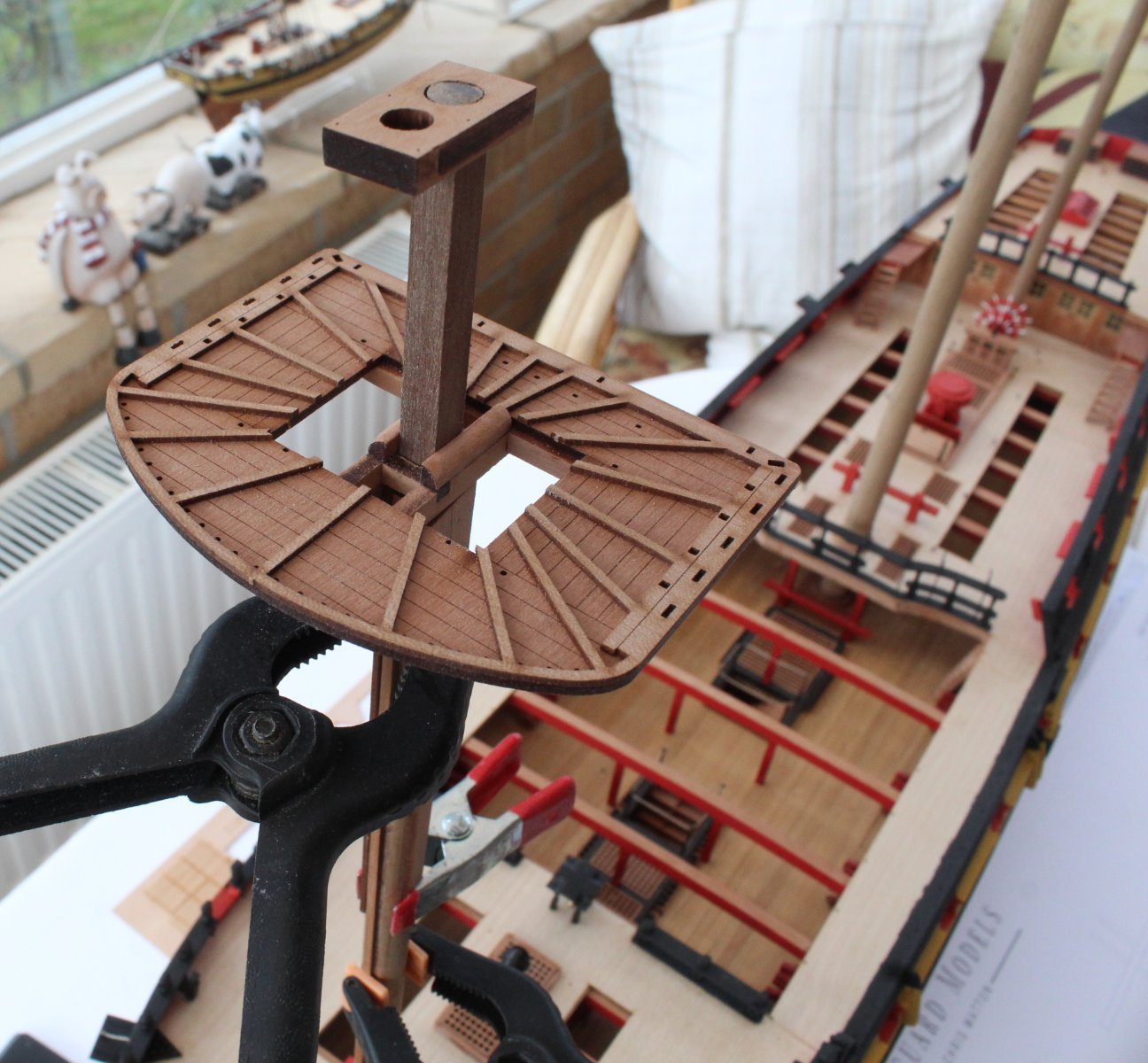
Using a piece of 6mm x 6mm dowel with a round end I was able to simulate the lower part of the next section of the foremast assembly. This was then used to ensure the lower foremast platform was correctly set when it was glued in place. I was really pleased with the alignment. In the next photo I have also added the iron bands (using black tape) and head battens (x8) to the square section of the lower foremast.
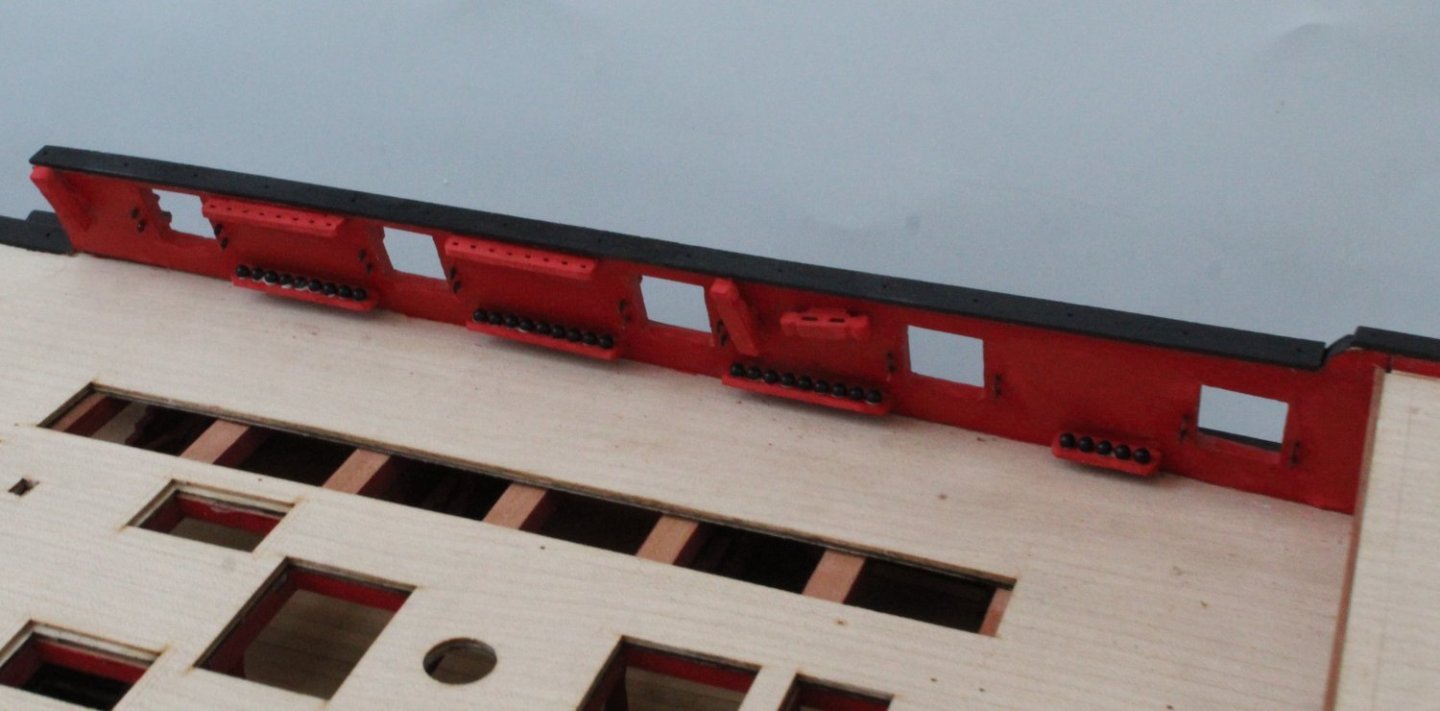
In the final photo I have also added the two cleats which are positioned between the head battens.
There is still a bit more work required to complete the lower foremast section, such as adding the main mast top stay block, the two main topsail bowline blocks, the two yard lift blocks, complete with thimbles, and the top rail assembly. The deadeye strops are also ready to be fitted. I need to make sure when these are added that I will leave enough room below the strop and above the platform for the belaying of the topmast shroud lines.