


Glenn-UK
-
Posts
3,004 -
Joined
-
Last visited
Content Type
Profiles
Forums
Gallery
Events
Posts posted by Glenn-UK
-
-
10 minutes ago, ECK said:
Sorry to hear. It is difficult to do a quick fix. Did you consider drilling into each end then putting a pin to help stabilize for the clamps and glue to dry ? Would not take long to try. Hate to see such a lovely build put up in ordinary as they would say. Look forward to your next one.
The damage was where the topgallant yard was pinned so not reallt possible to add a pin with repositioned the topgallant yard. I did consider a few different options.
-
MY FINAL BRIG ADDER BUILD LOG POST
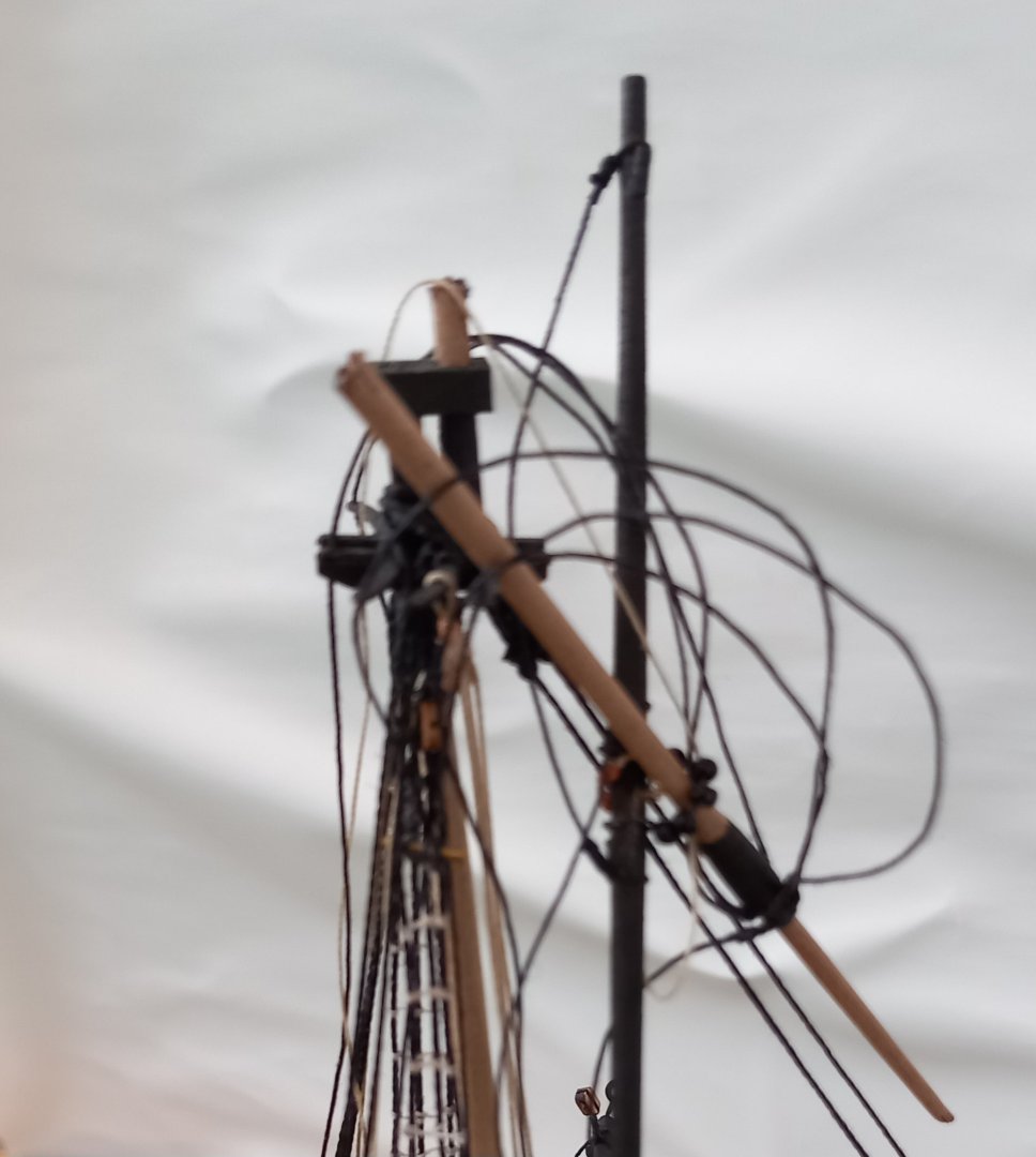
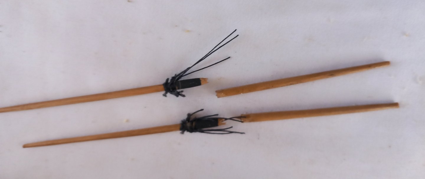
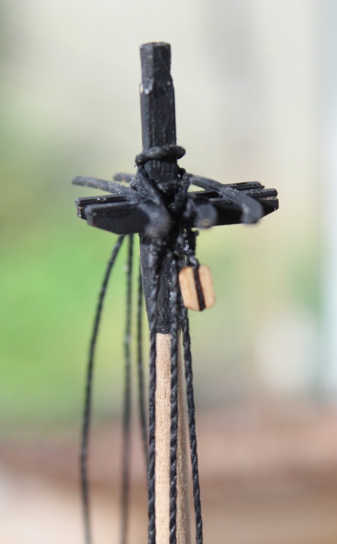
I had about another weeks work left to complete the Brig Adder as I only had the yard braces and lifts to rig. This would have tied in nicely with the expected release date for the Harpy, which is my next build project.Unfortunately when I started work on the Adder this afternoon I noted the fore topgallant mast had been damaged, I can only assume I knocked yesterday when I was adding one of the fore topsail yard jeers. After trying to repair the damage I ended up making matters far worse and realised that I would have to remove fore topgallant mast and all of its associated rigging. Once that was done I would then have to make a new topgallant mast and redo all the rigging. I know from experience, with the Indy, that this is not an easy repair. The most difficult aspects are trying to remove the damaged mast from the end cap and the shroud rigging that is belayed around the topsail deadeye strops.
This is a photo of the damage.
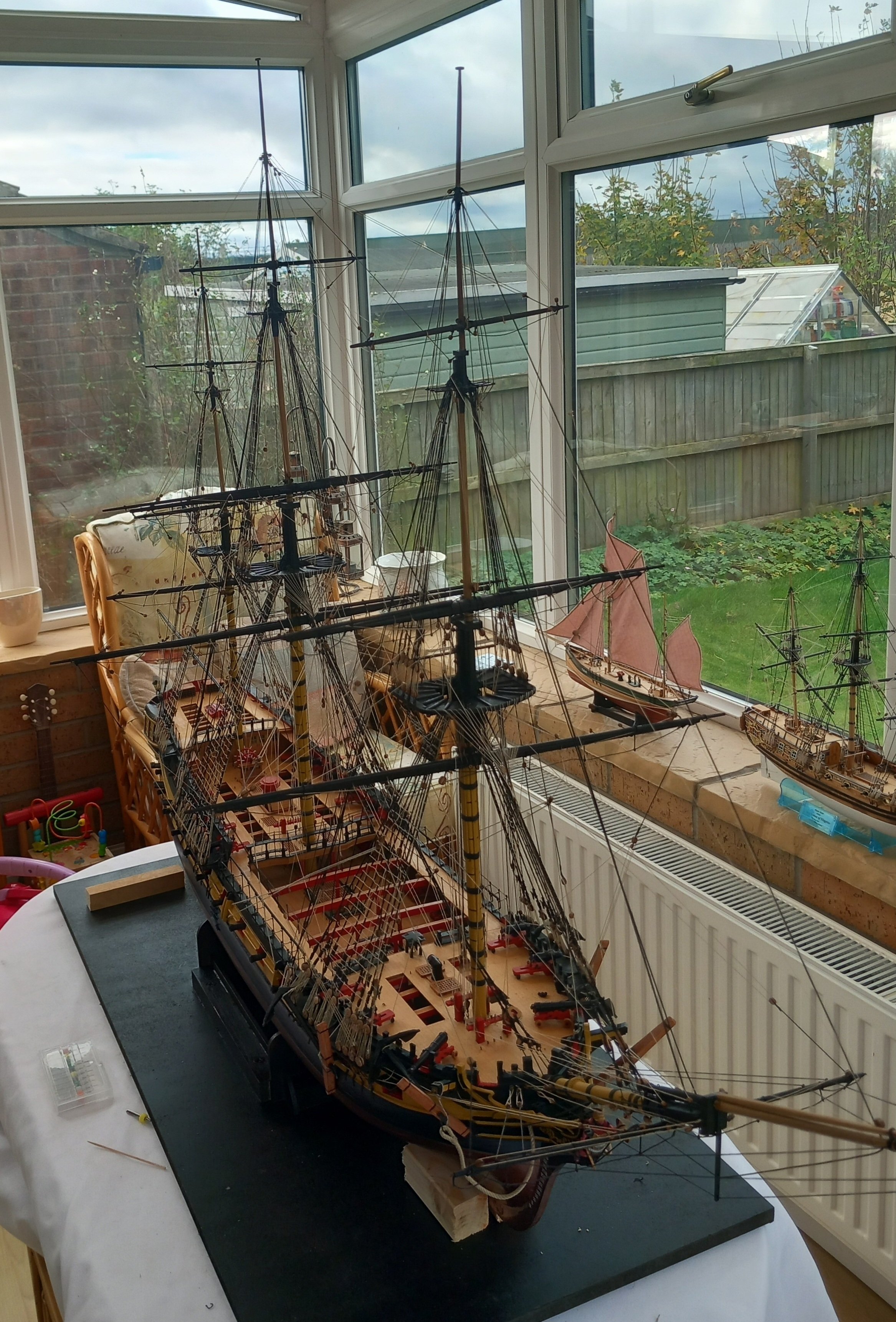
I have really enjoyed building the Brig Adder but my interest in model boats, as a hobby, is the building process and developing methods to make the building process easier. I was so pleased when someone bought my Indy as there is no room left in the house to display all of my completed models. At the moment I have two small Vanguard Models fishing boats on display on the living room. The Sphinx is on display in the dining room and both the Alert and Duchess of Kingston are on display in the conservatory.
I have decided to stop work on the Adder;
a) I do not have the space to display the Brig Adder when completed
b) My next build (Harpy) is due to released in the next week or two which I will want to start immediately.
c) I do struggle with some aspect of the rigging due to my poor close vision
d) I may end up doing more damage when I try to remove the damaged mast and associated rigging
Thank-you to everyone who has been following and commenting / liking my Brig Adder build log posts it is greatly appreciated. Many thanks also to @chris watton for designing and selling this amazing kit and I am sorry Chris that I have sadly failed to cross the finish line when I was so close to the end. I have already downloaded then Harpy manual so my free time will be spent reading the manual and checking out @James H excellent Harpy build log.
-
1 hour ago, chris watton said:
I have been told that Harpy printed materials should be with me by the end of next week.
I have just put a deposit down on a second large laser machine, which has more power (100w) and larger bed size, with my very first little 40w machine as part exchange, as this is redundant now. Quite an investment, but I believe is necessary for the future growth of VM.
Good news with the Harpy as I am waiting like an expectant father for its arrival.🤣
I am very pleased that VM is growing and is testament to your philosophy with regards to providing high quality kits.
- thibaultron, chris watton, DB789 and 9 others
-
 12
12
-
Date: 20/11/2024
Time worked today: 4 hours.
Total time spent on build: 140 hours.
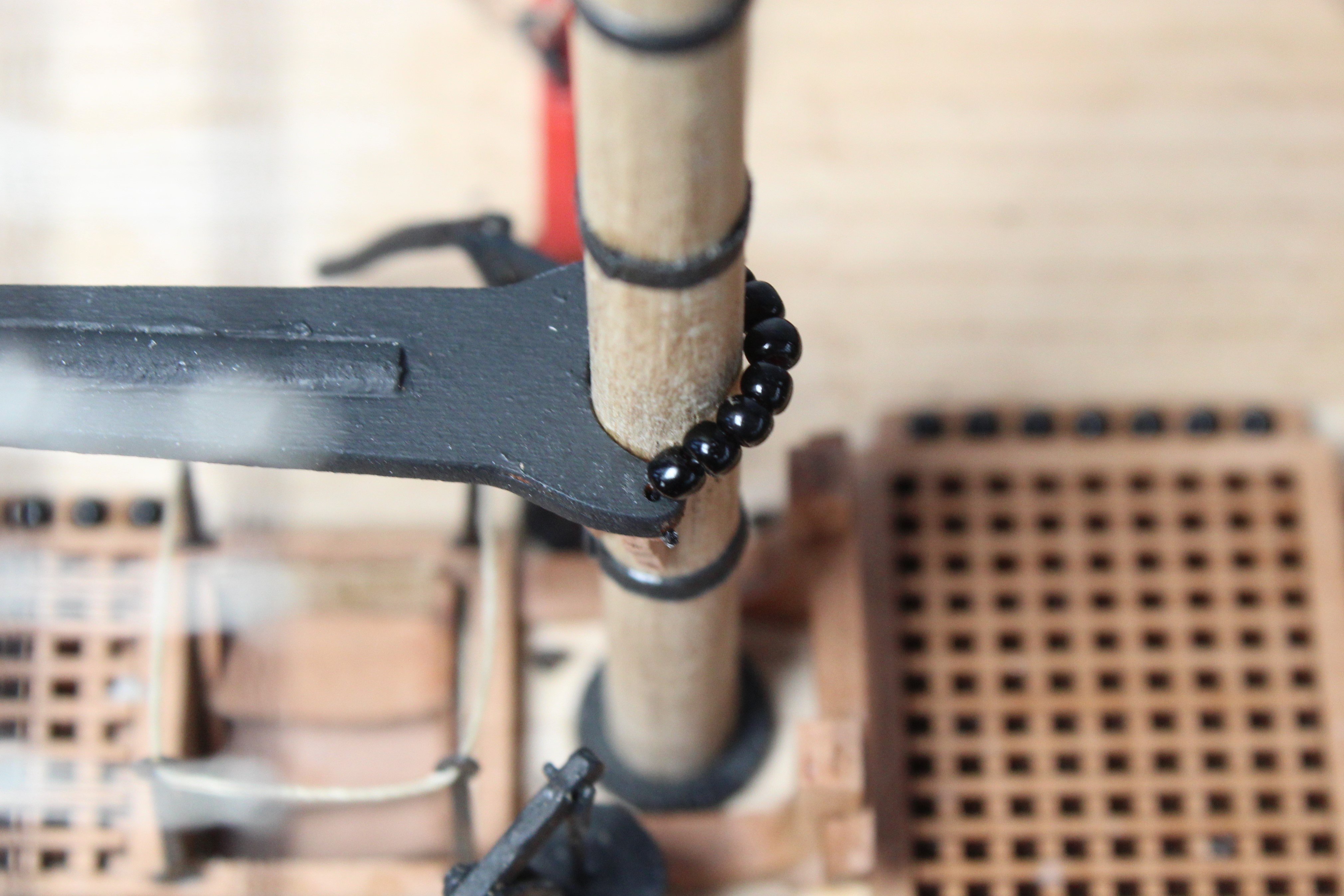
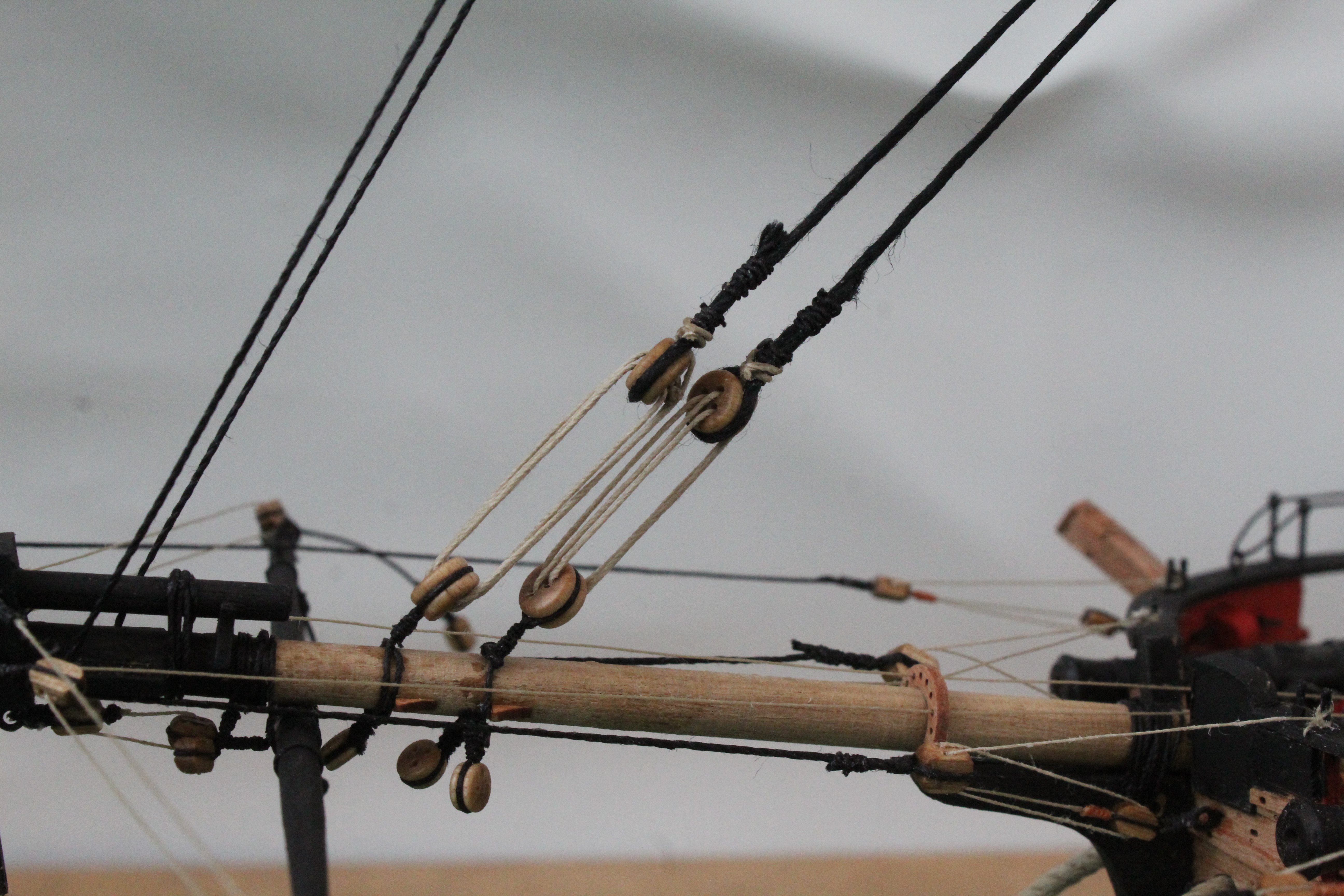
Gaff Boom and Main / Fore Yard Jeers
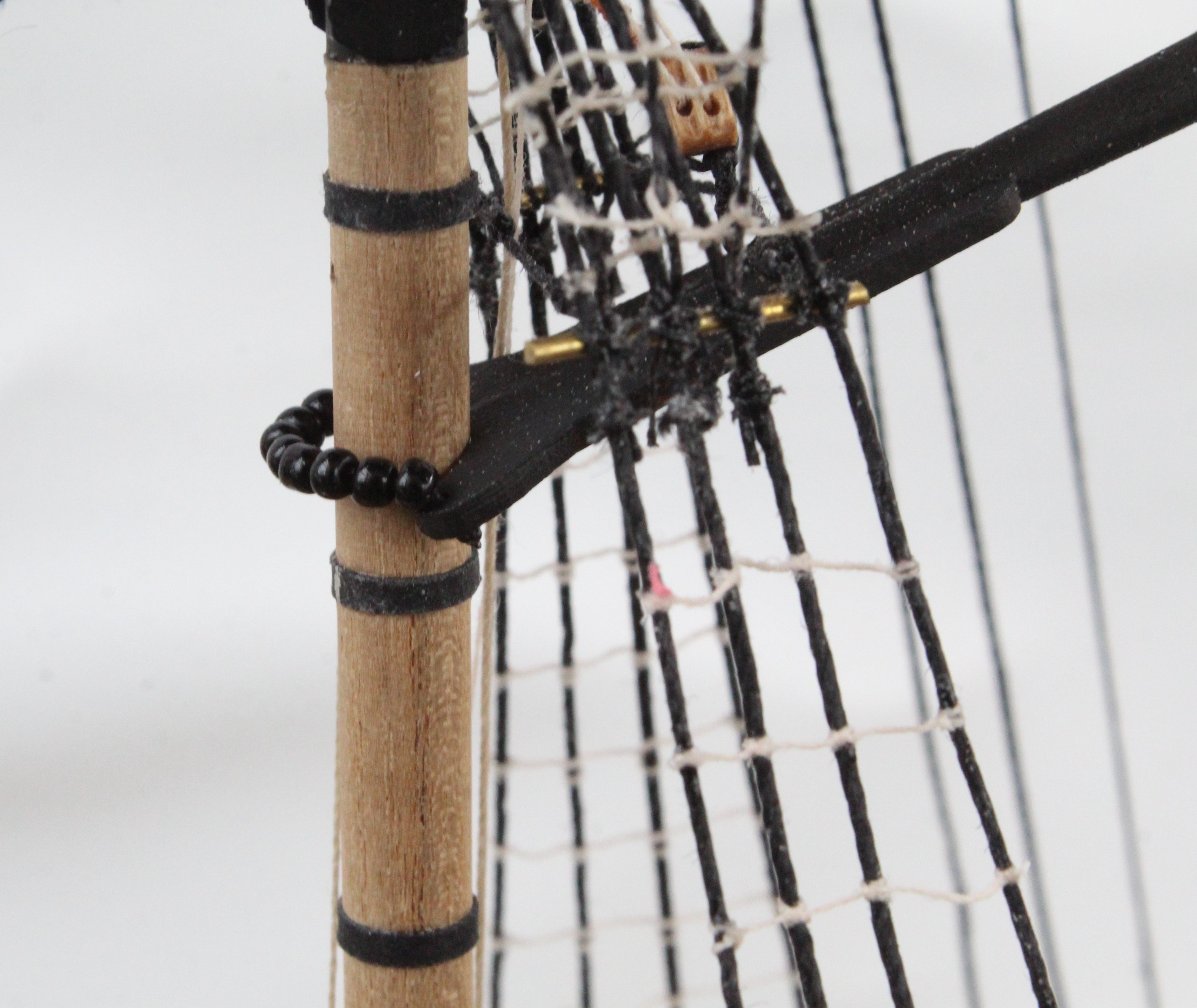
Adding the running rigging for the gaff boom was a bit more involved compared with the driver boom but not to taxing. With the gaff boom secured to the mast via the parrel beads all the other running rigging was installed and adjusted and belayed. I was happy with the result.


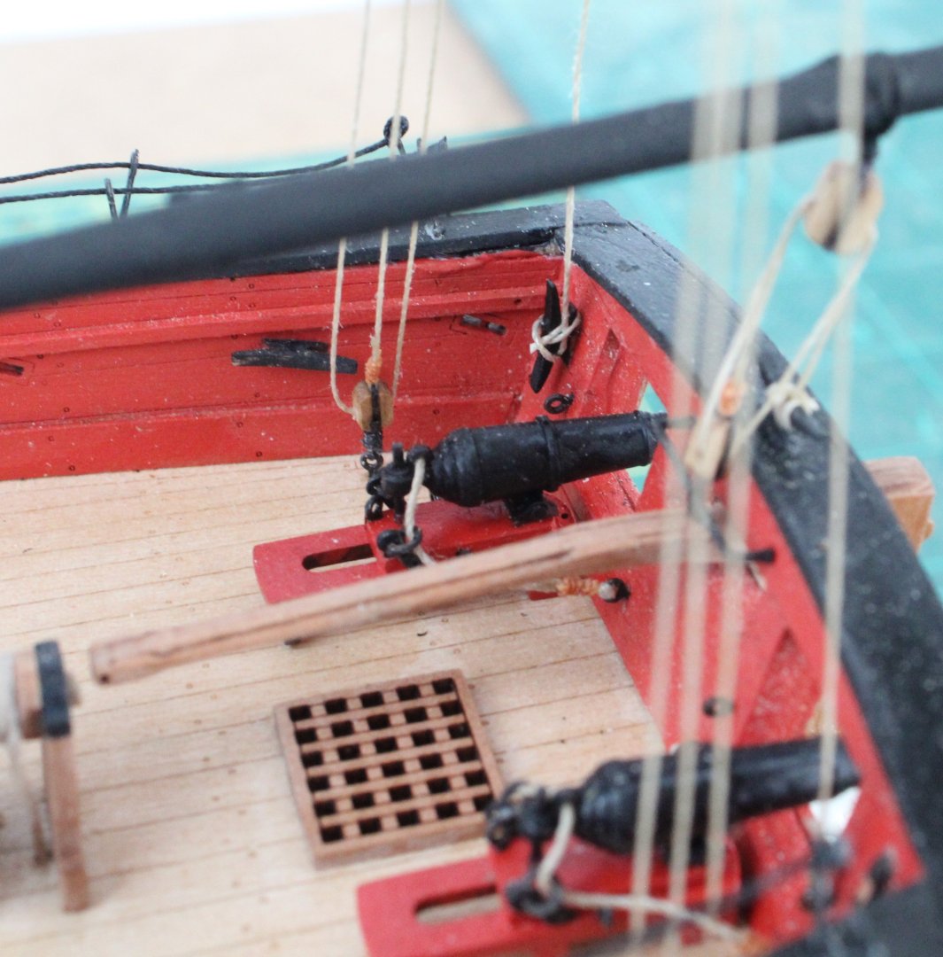
I then secured the main and fore yards to their respective masts and added the jeer rigging.
- rcweir, Knocklouder, chris watton and 6 others
-
8
-
 1
1
-
Date: 19/11/2024
Time worked today: 2 hours.
Total time spent on build: 136 hours.
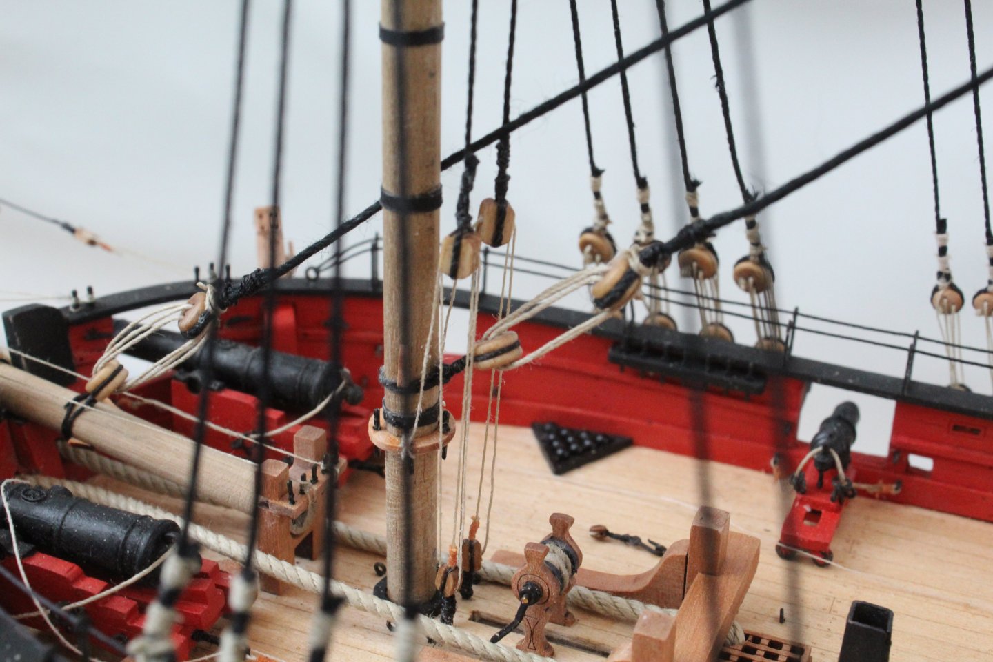
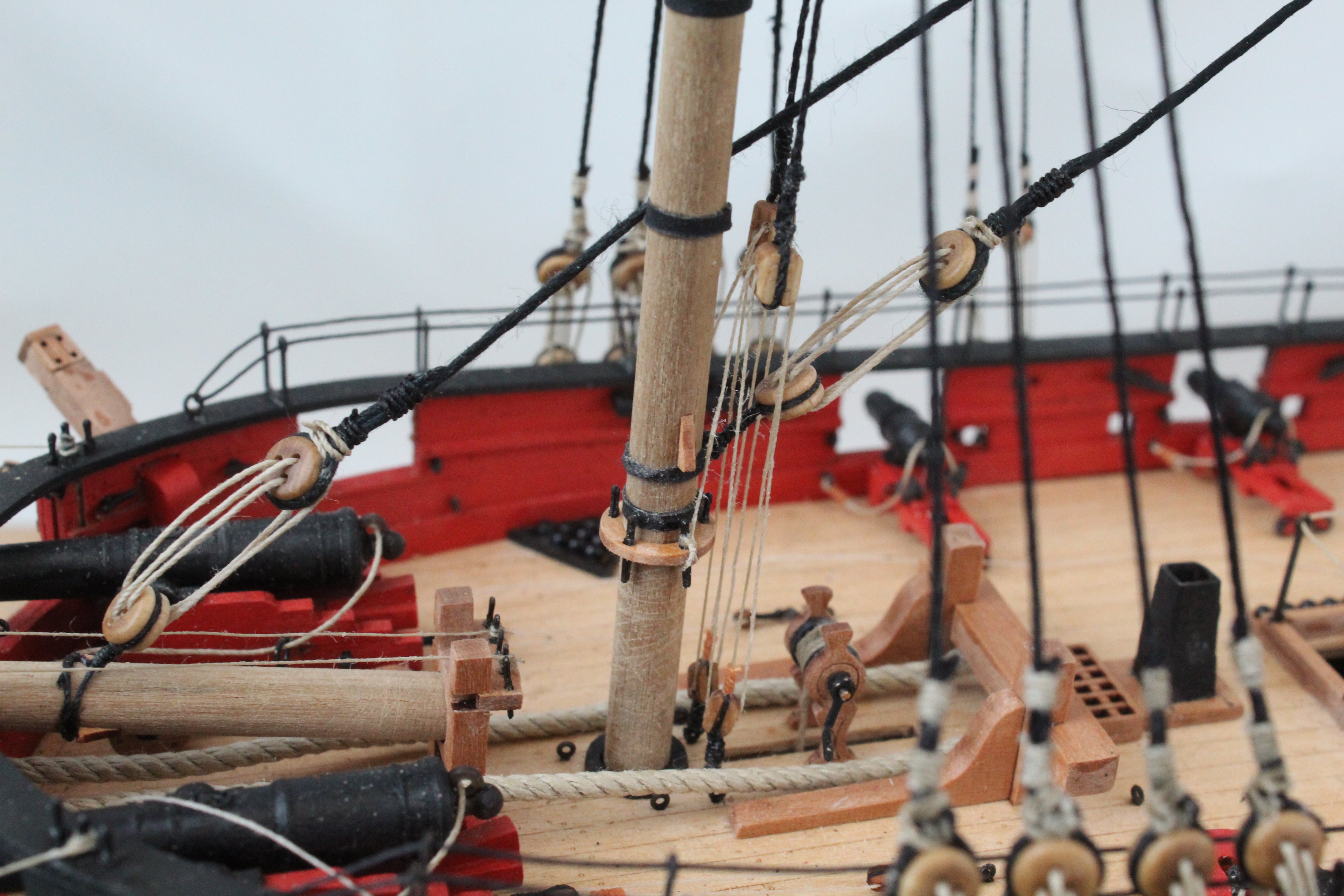
Driver Boom Running RIgging
This was a mundane and simple task to complete.
Step 1
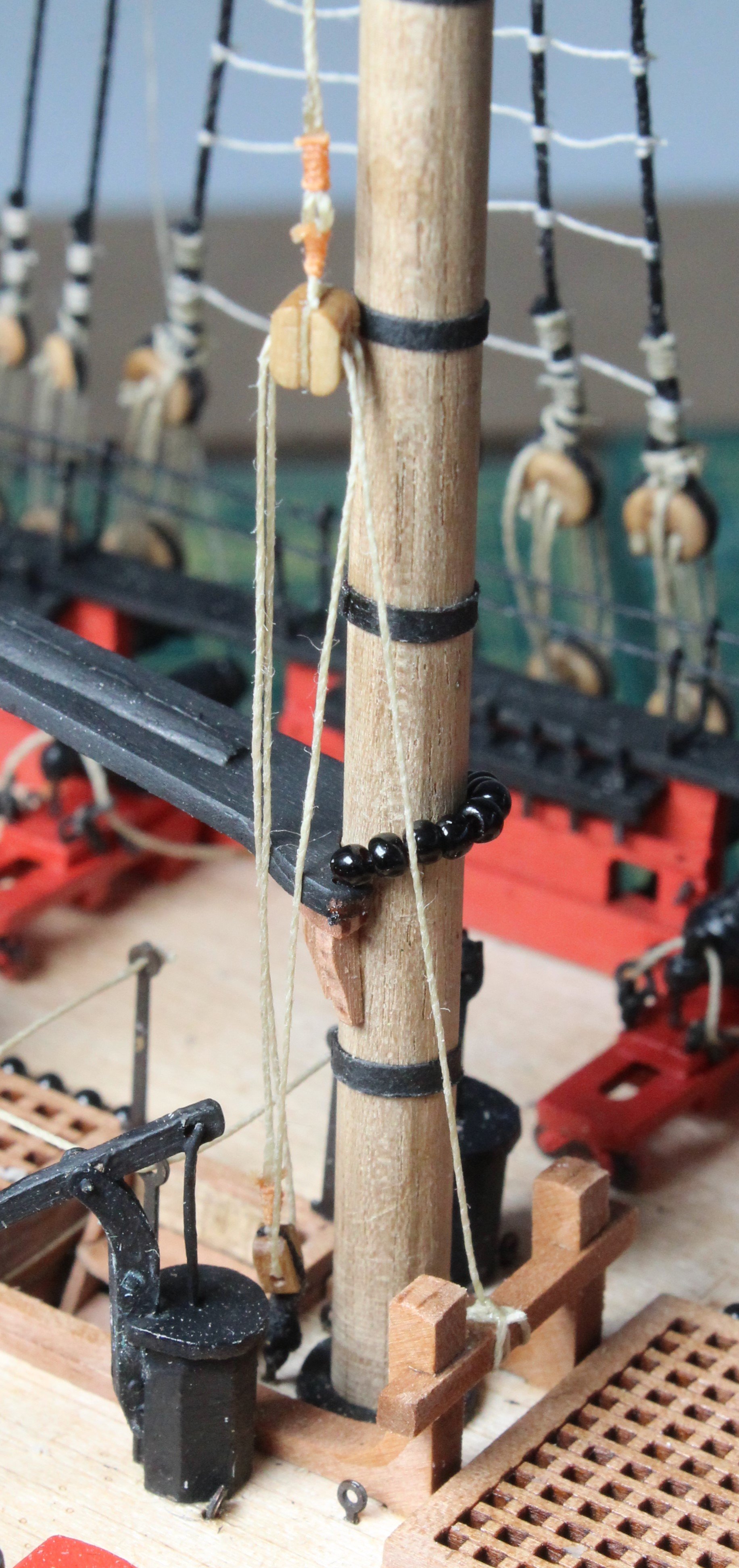
The driver boom was added to the main mast as shown below.
 Step 2
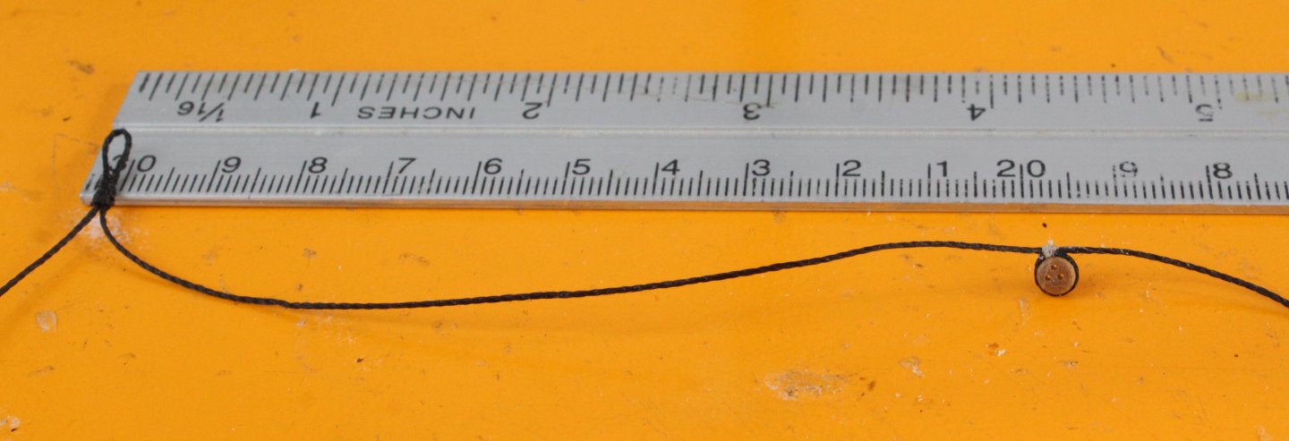
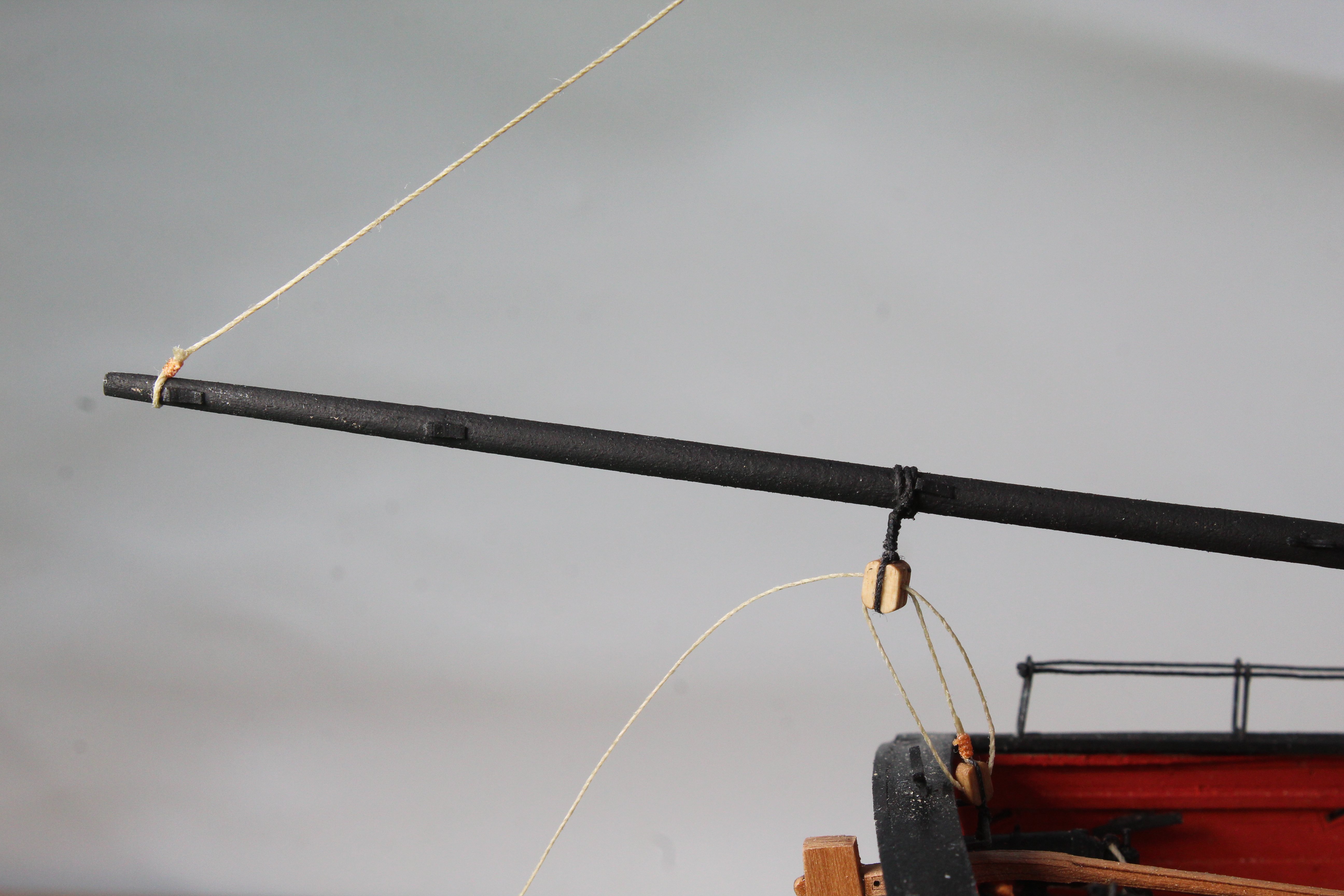
The inter-block rigging, shown in the next photo was then added, but not belayed.
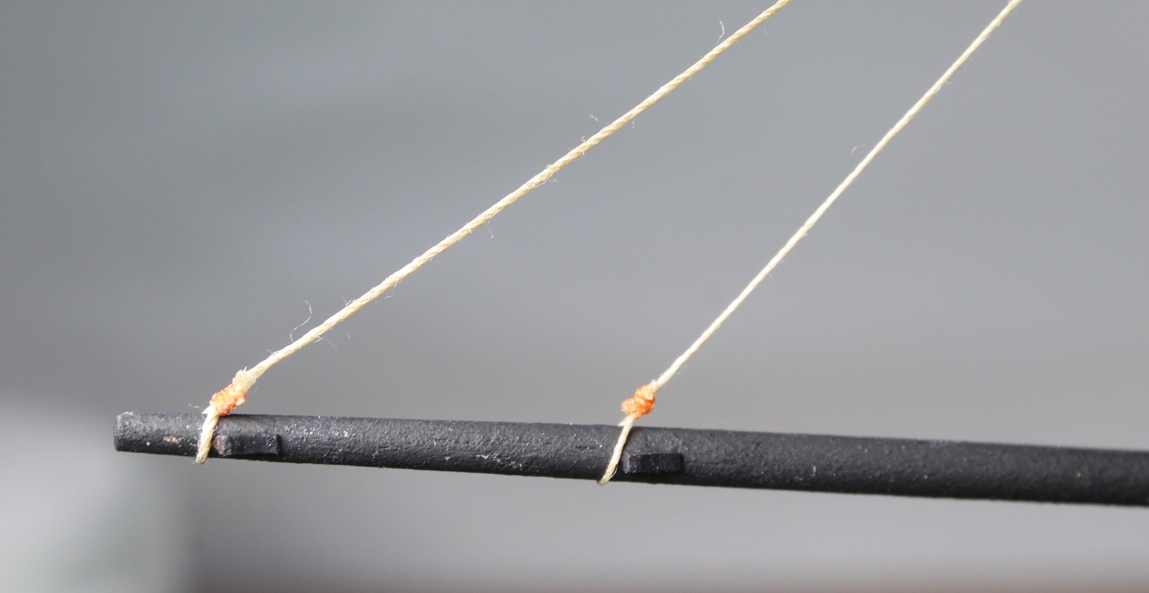
Step 3
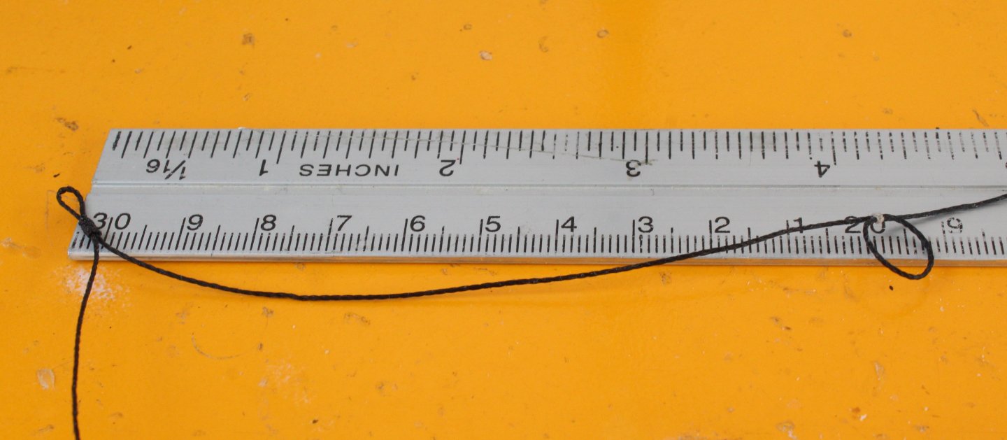
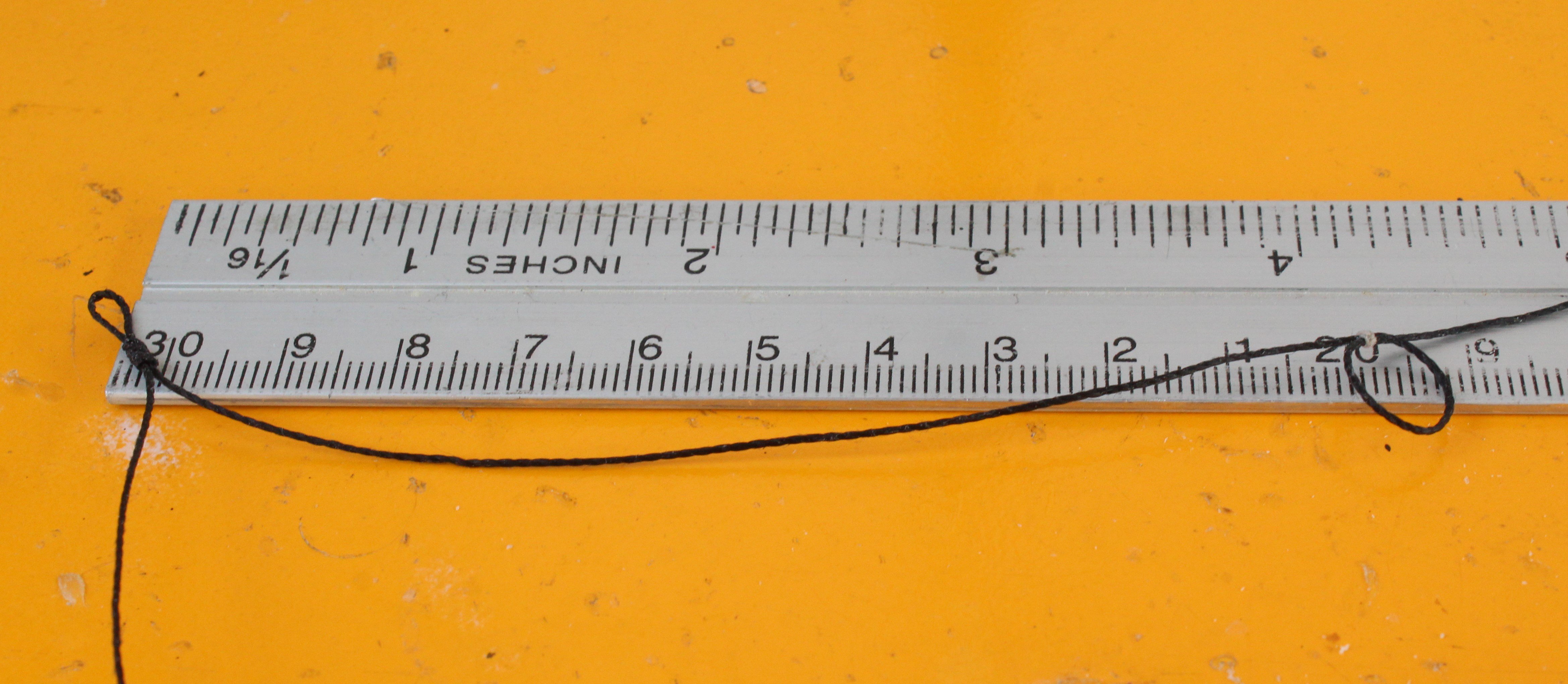
Next a length of thread was added to the end of the driver boom.
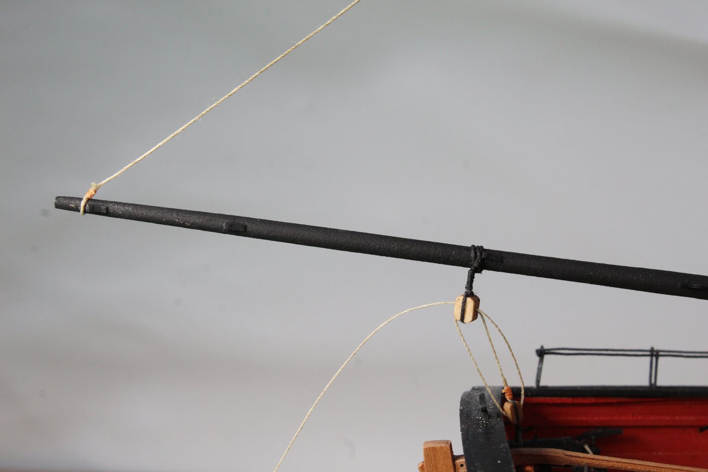
Step 4
This thread was then reeved through a block on the main mast.
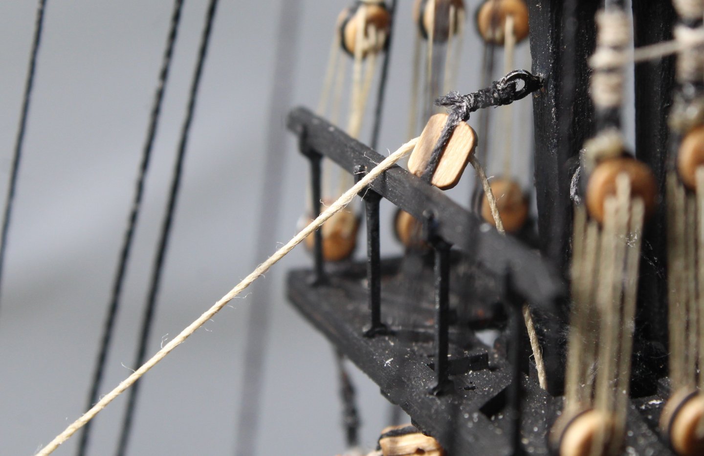
Step 5
The first inter-block block was then belayed.

Step 6
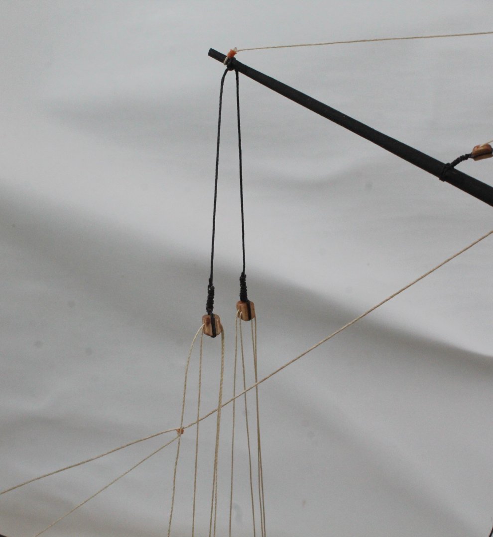
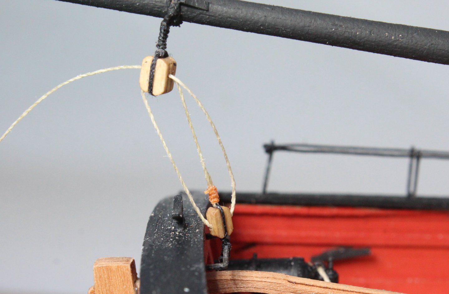
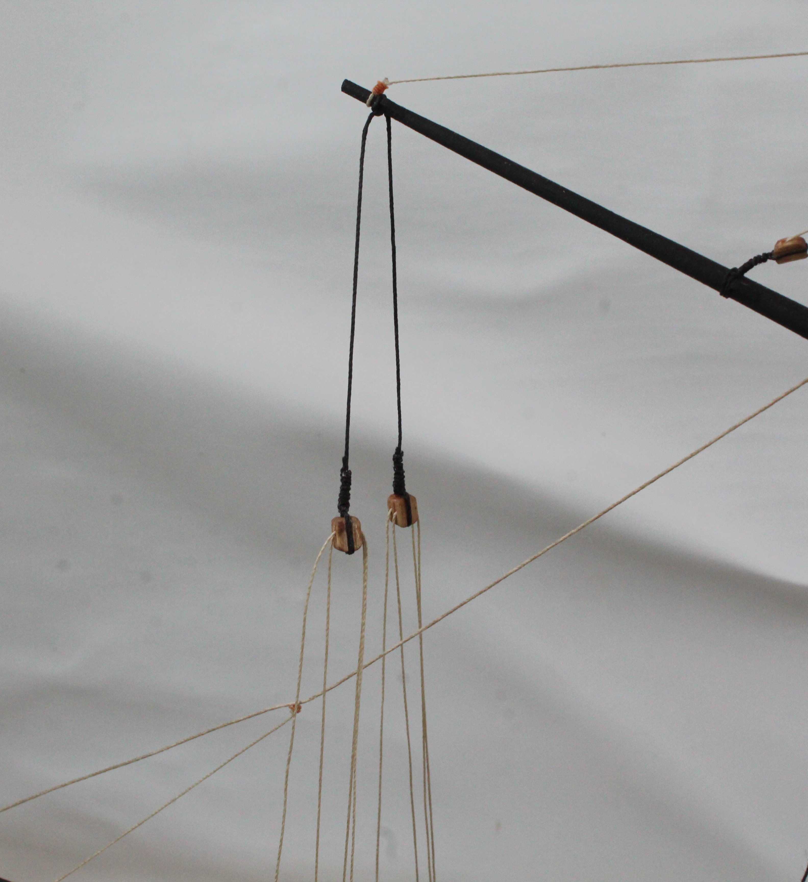
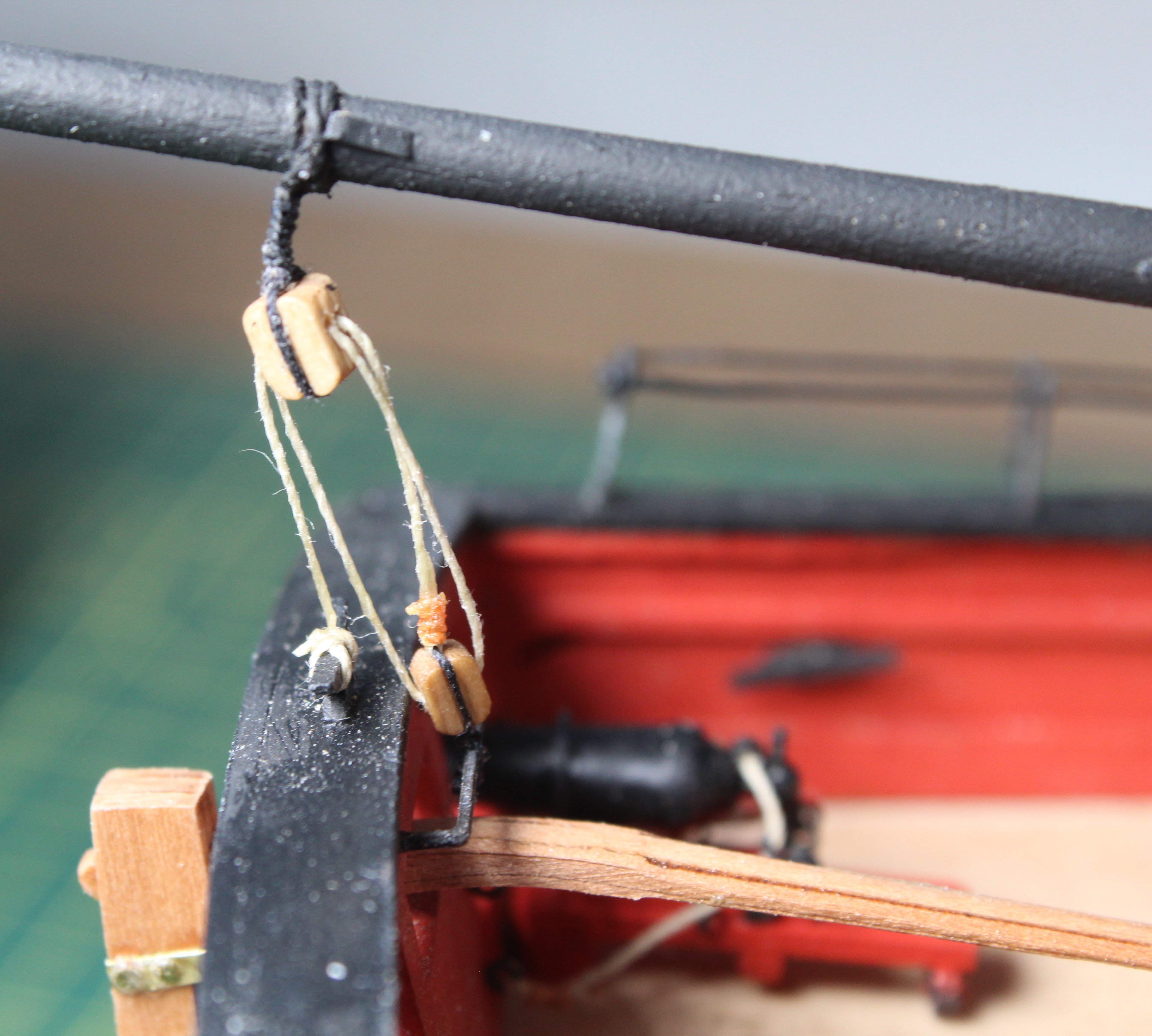
The thread from the end of the driver boom was then belayed to deck, via a double block arrangement, as shown below.

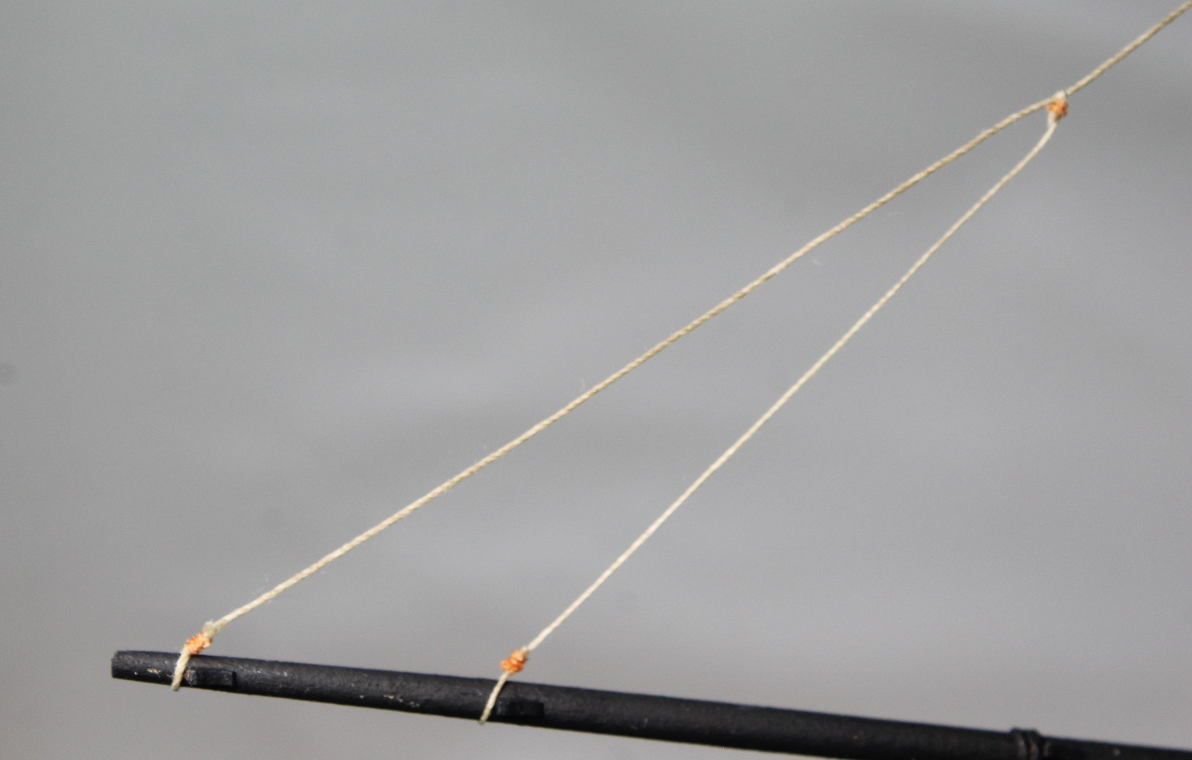
Step 7
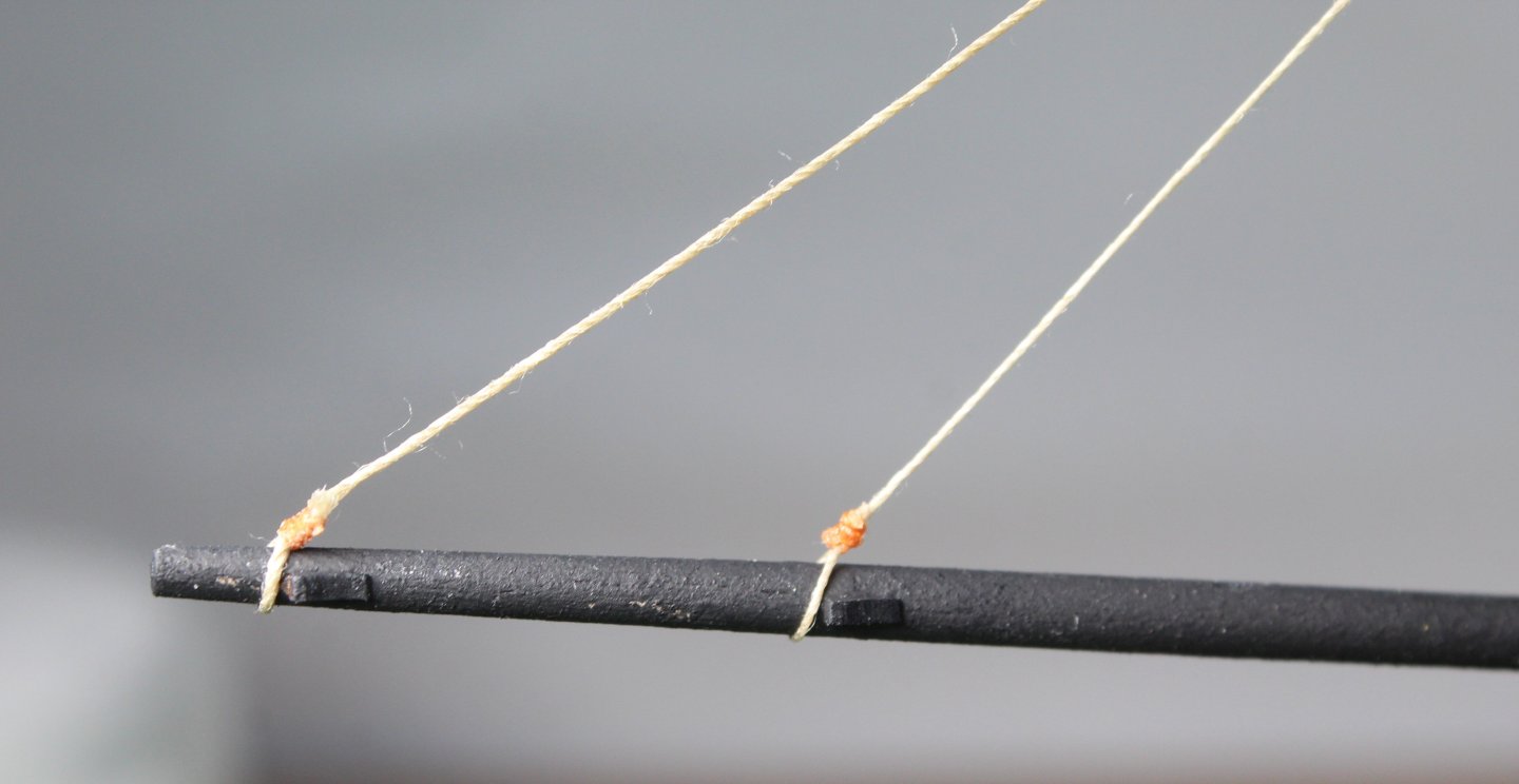
The final task was to add a second thread, as shown in the next two photos
-
Date: 19/11/2024
Time worked today: 2 hours.
Total time spent on build: 136 hours.
Driver Boom Running RIgging
This was a mundane and simple task to complete.
Step 1
The driver boom was added to the main mast as shown below.
Step 2
The inter-block rigging, shown in the next photo was then added, but not belayed.
Step 3
Next a length of thread was added to the end of the driver boom.
Step 4
This thread was then reeved through a block on the main mast.
Step 5
The first inter-block block was then belayed.
Step 6
The thread from the end of the driver boom was then belayed to deck, via a double block arrangement, as shown below.
Step 7
The final task was to add a second thread, as shown in the next two photos
- DB789, Oboship, chris watton and 2 others
-
5
-
Date: 19/11/2024
Time worked today: 10 hours.
Total time spent on build: 134 hours.
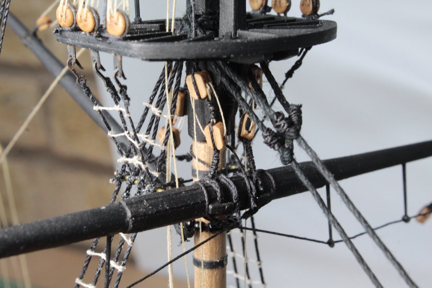
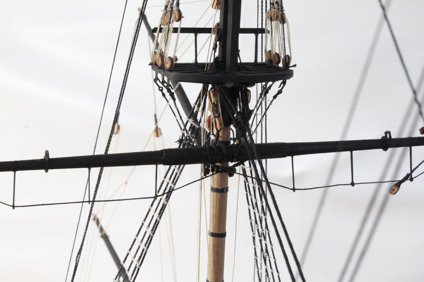
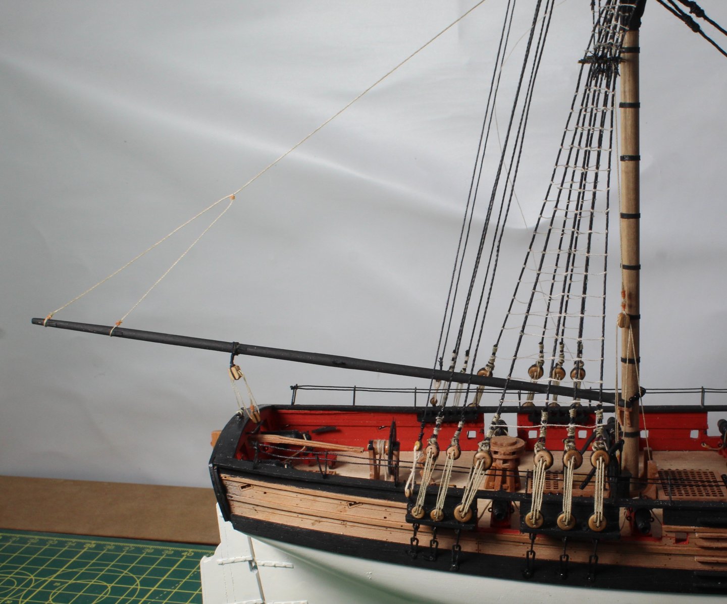
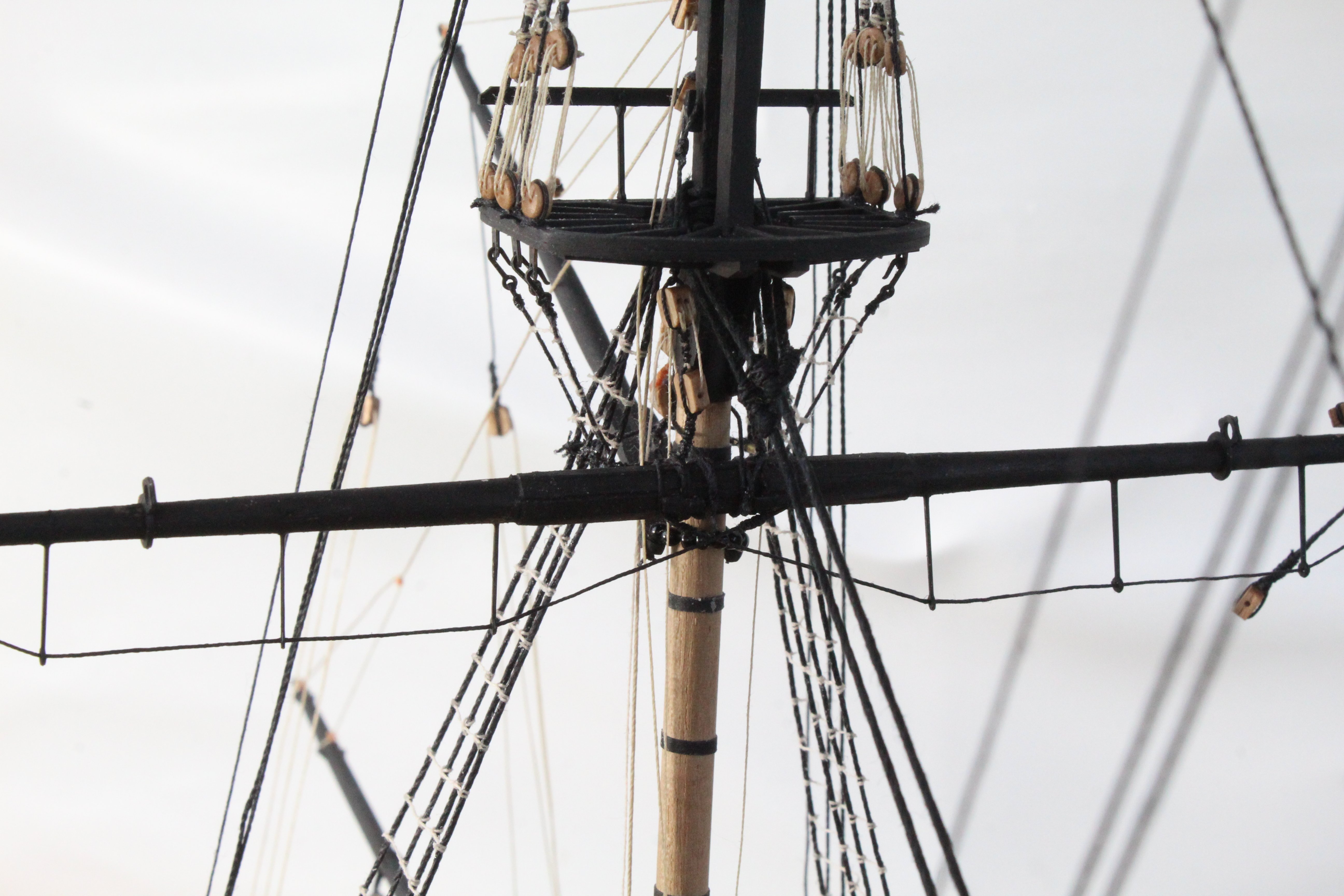
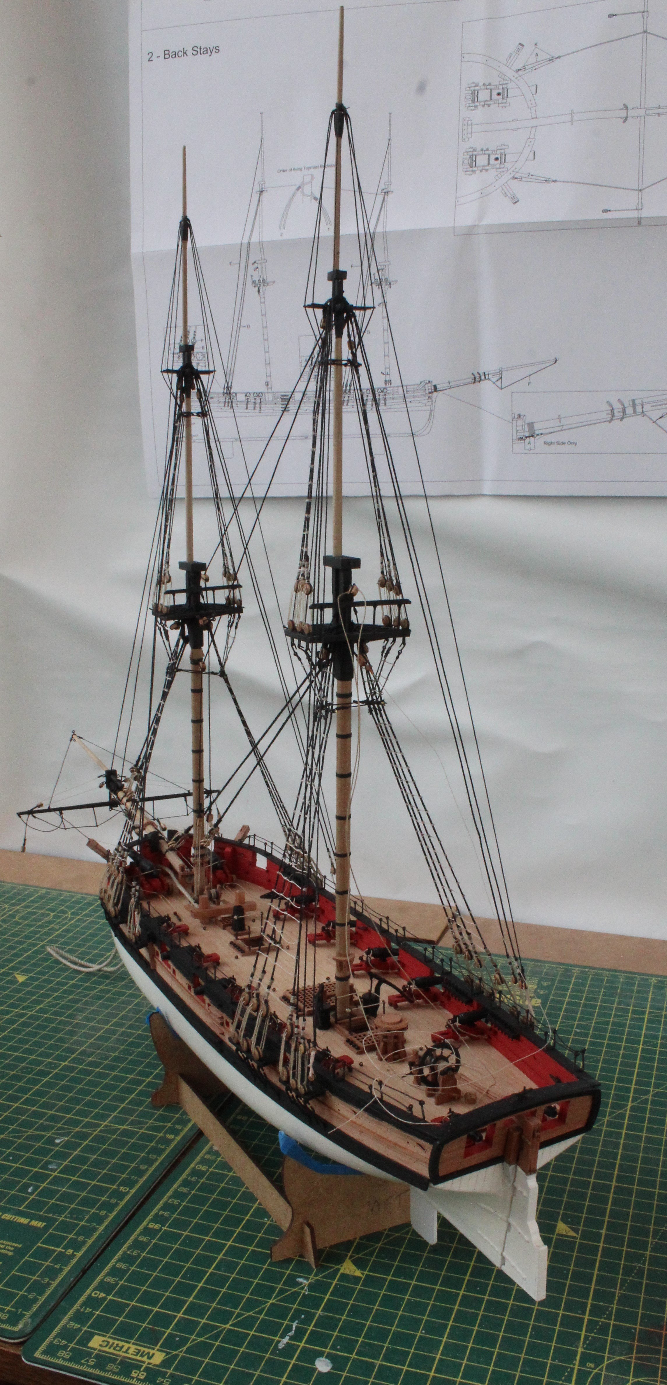
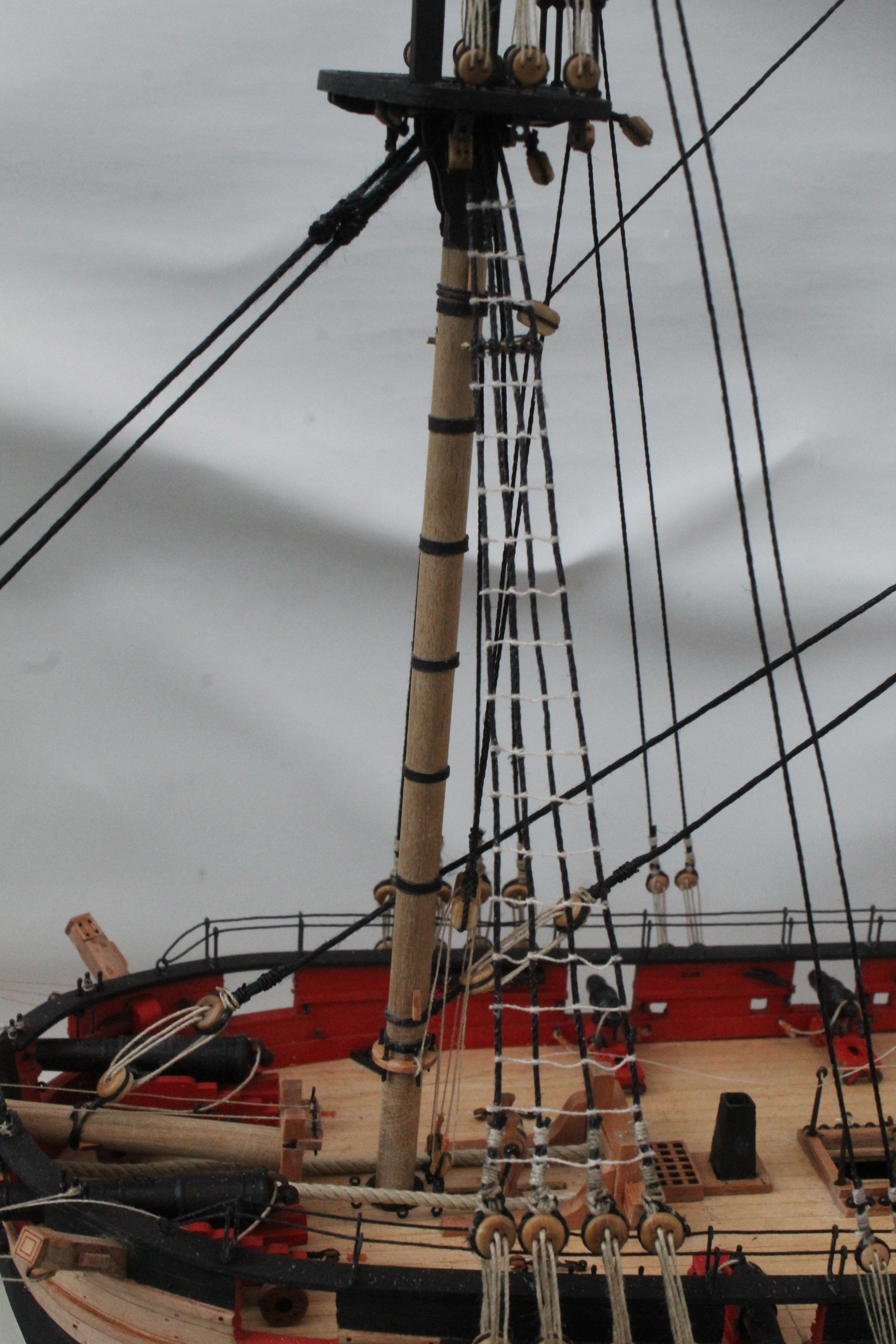
Shrouds, Ratlines, Stays and Backstays
I have finally completed adding all the shrouds and ratlines. I have also completed all work related to the stays and backstays.
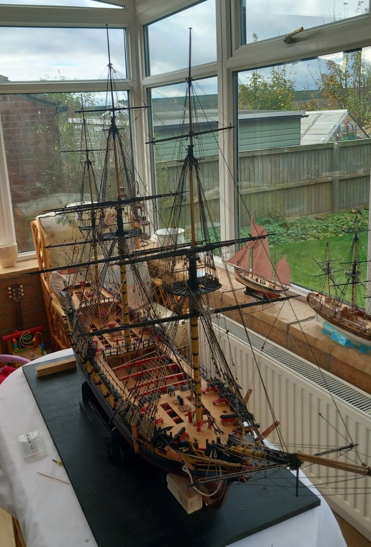
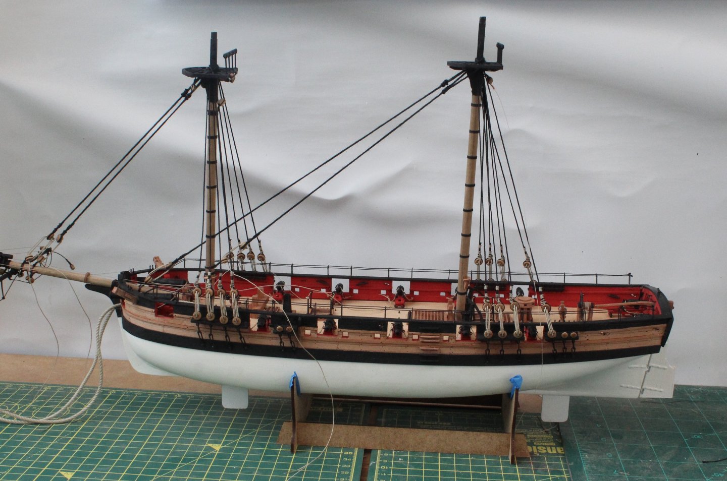
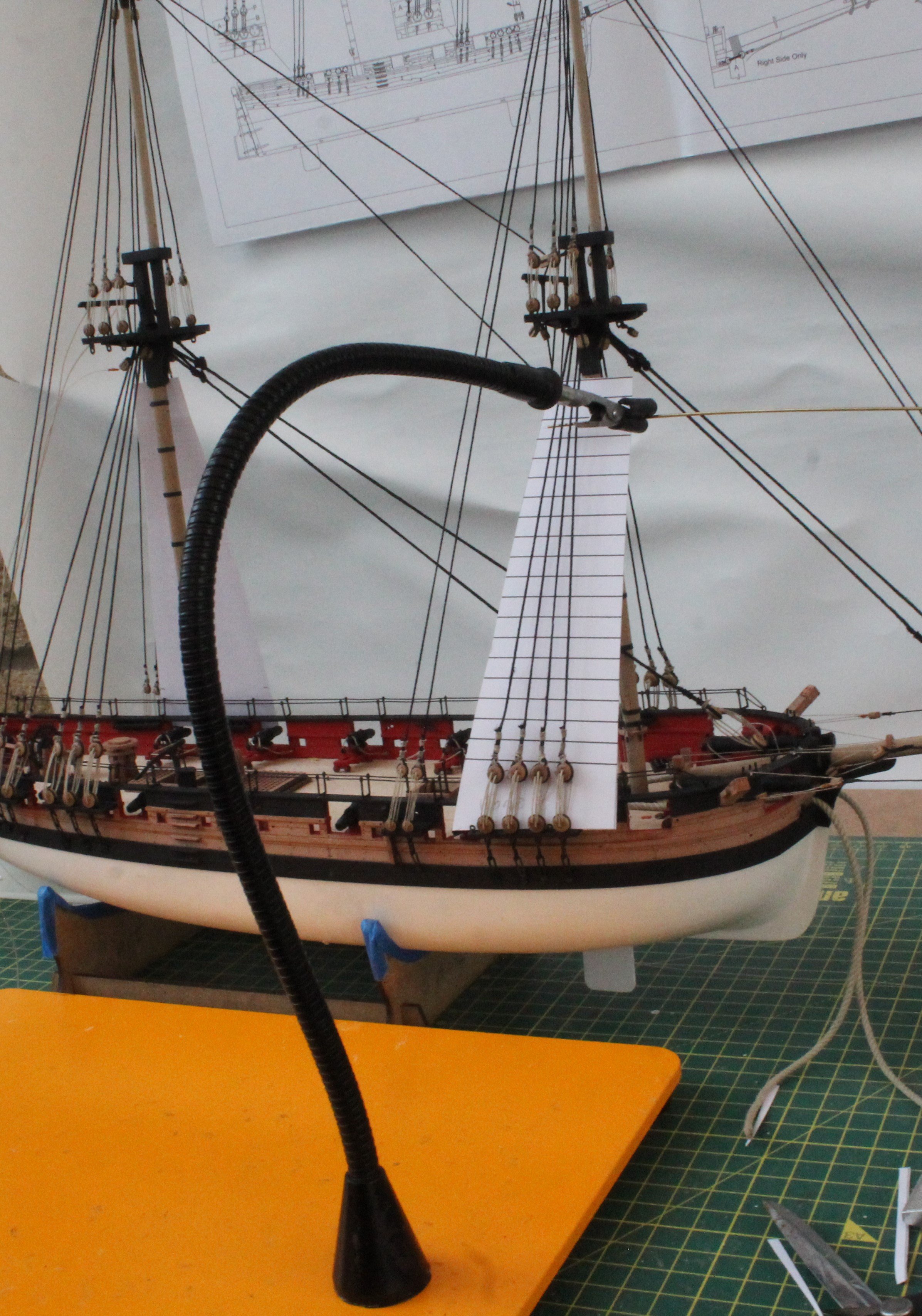
I find it is difficult to take good quality photos at this stage of the build process. I have attached a couple of photos showing the current build and a three showing some of the rigging.
I will now look at adding the running rigging for the driver boom and gaff boom. Once that is done it will time to add and rig all the masts. This means the end is now in sight and it should tie in nicely with my next project as I now have the Harpy on pre-order with Vanguard Models.

- chris watton, dunnock, Ryland Craze and 4 others
-
7
-
34 minutes ago, chris watton said:
Well, Surprise isn't exactly 'Just around the corner', this will be a latter half of 2025 release.
Just in time to order after I have finished the Harpy

- CiscoH, mtaylor, HardeeHarHar and 4 others
-
7
-
-
Another masterclass in building. I am looking forward to building the Harpy
- James H, Jack12477, chris watton and 3 others
-
6
-
Great news. I will be placing an order for the Harpy.
- Oboship, Nirvana, Ryland Craze and 4 others
-
7
-
Date: 08/11/2024
Time worked today: 4 hours.
Total time spent on build: 124 hours.
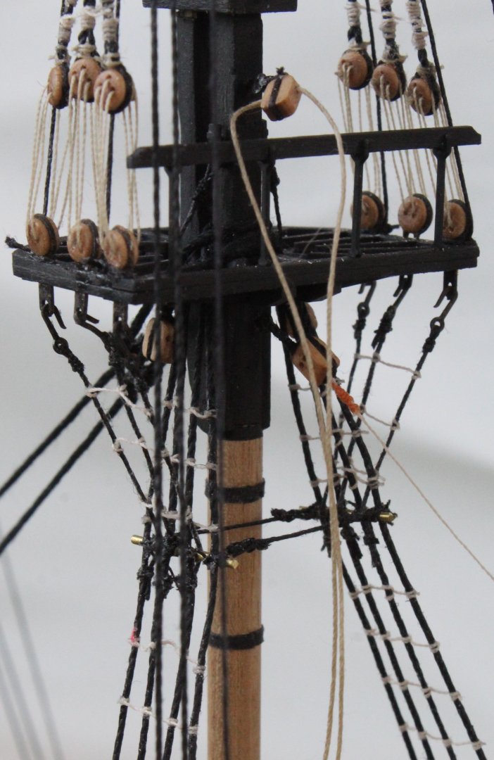
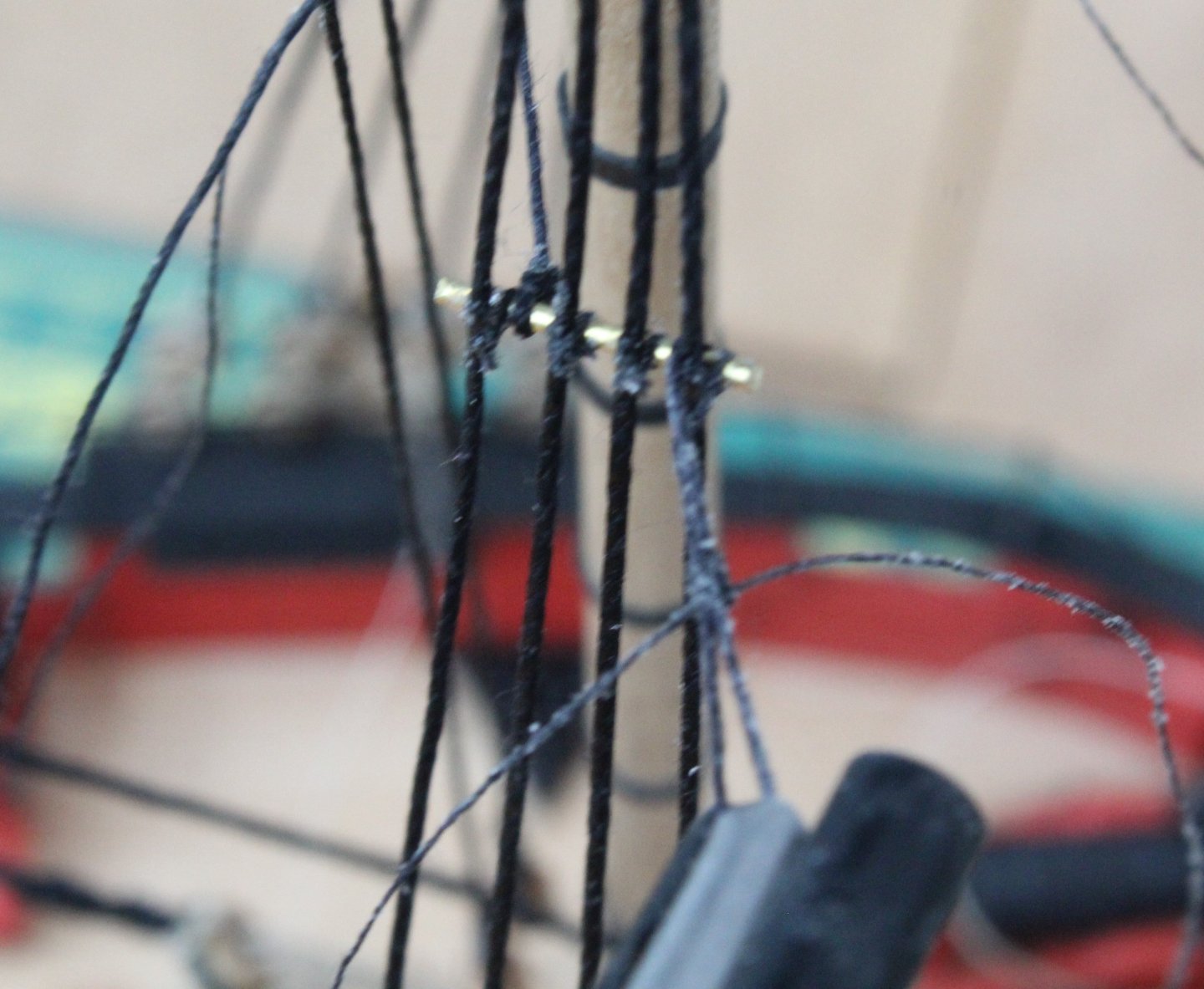
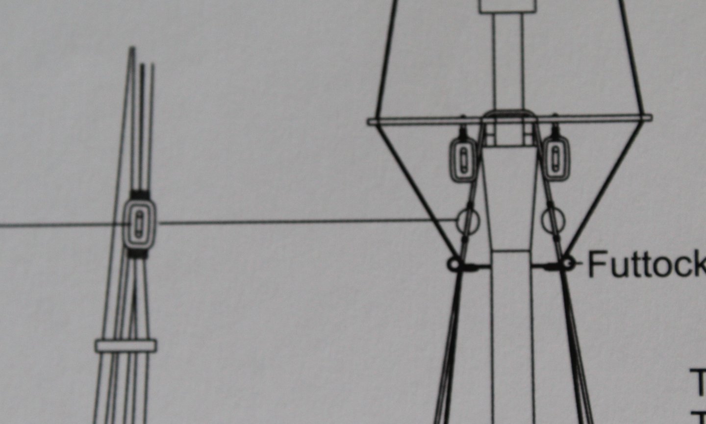
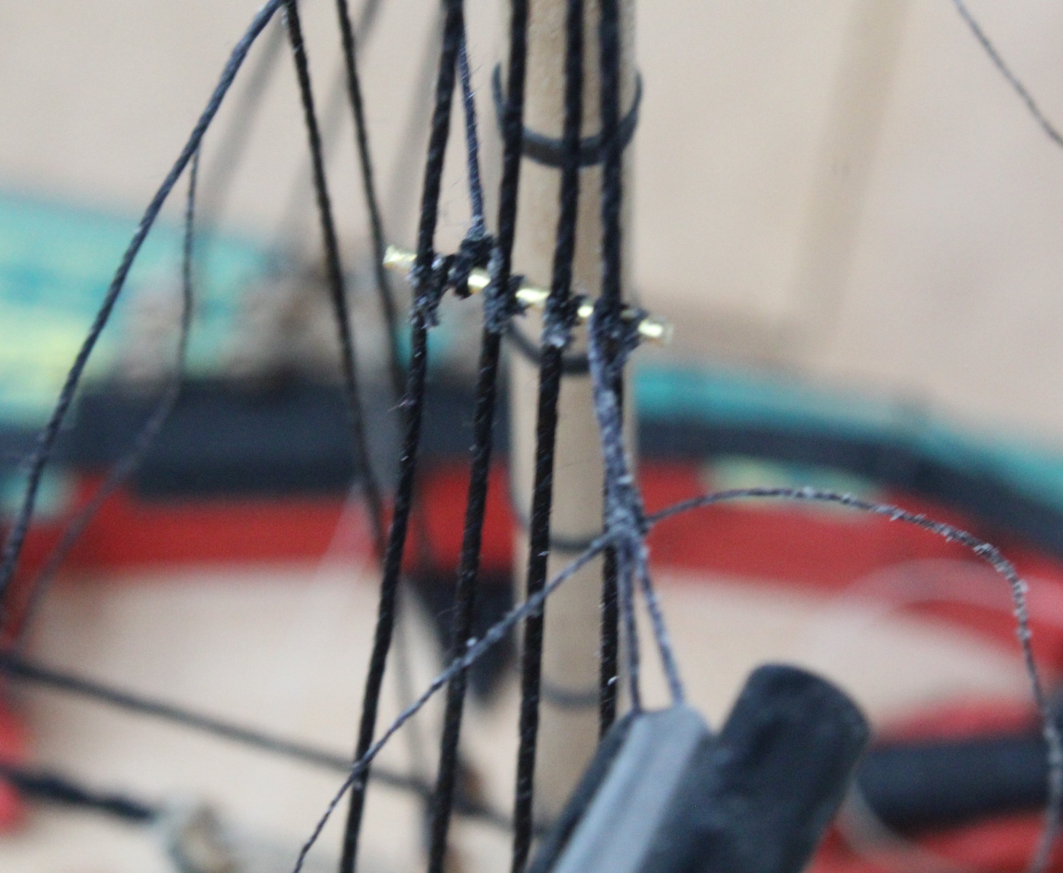
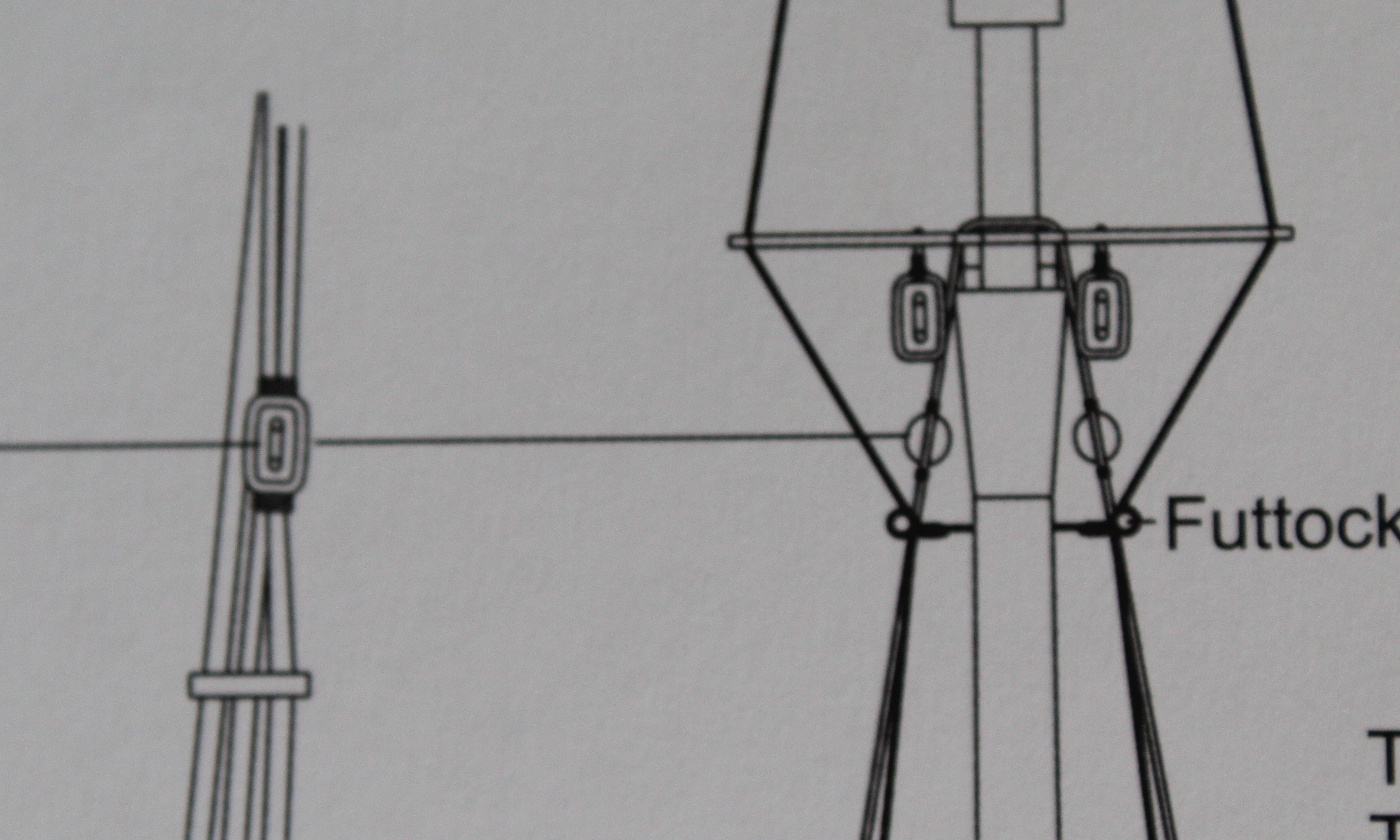
Futtock Staves and Catharpins
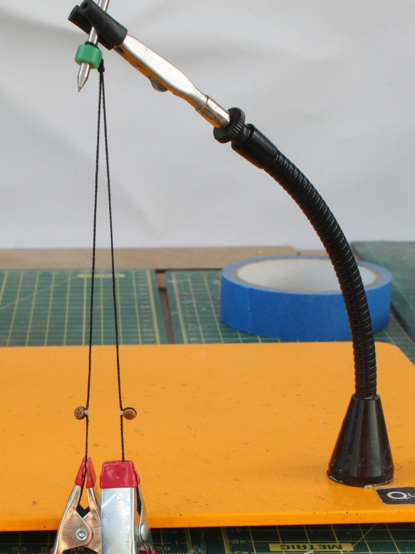
I have started to add the futtock staves and catharpins. When adding the futtock staves I used the quad hands to hold the staves in place.

I did use a template to make to help position the staves.
It was then a case of securing the stave to the shrouds. In the photo below I have secured the staves both ends. I did secure the stave to the middle two shrouds after I took the photo

The quad hands were used when adding the catharpins. With the one end of the catharpin thread wrapped around the stave I was able to add the seizing.
It did not take two long to complete the process.

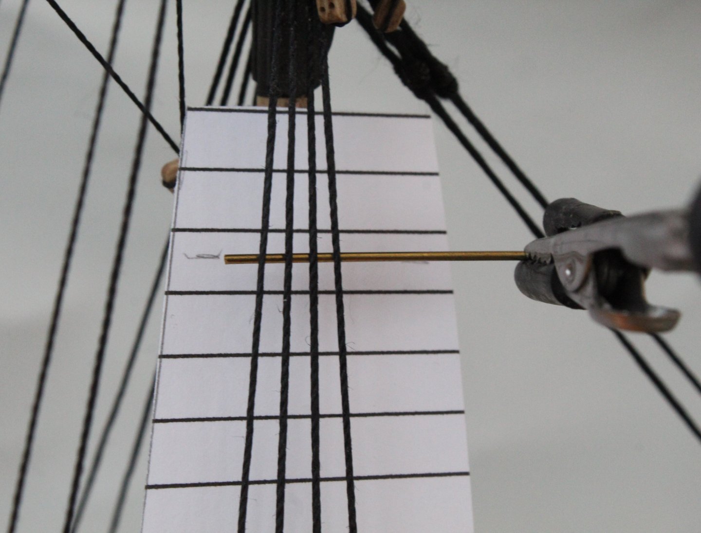
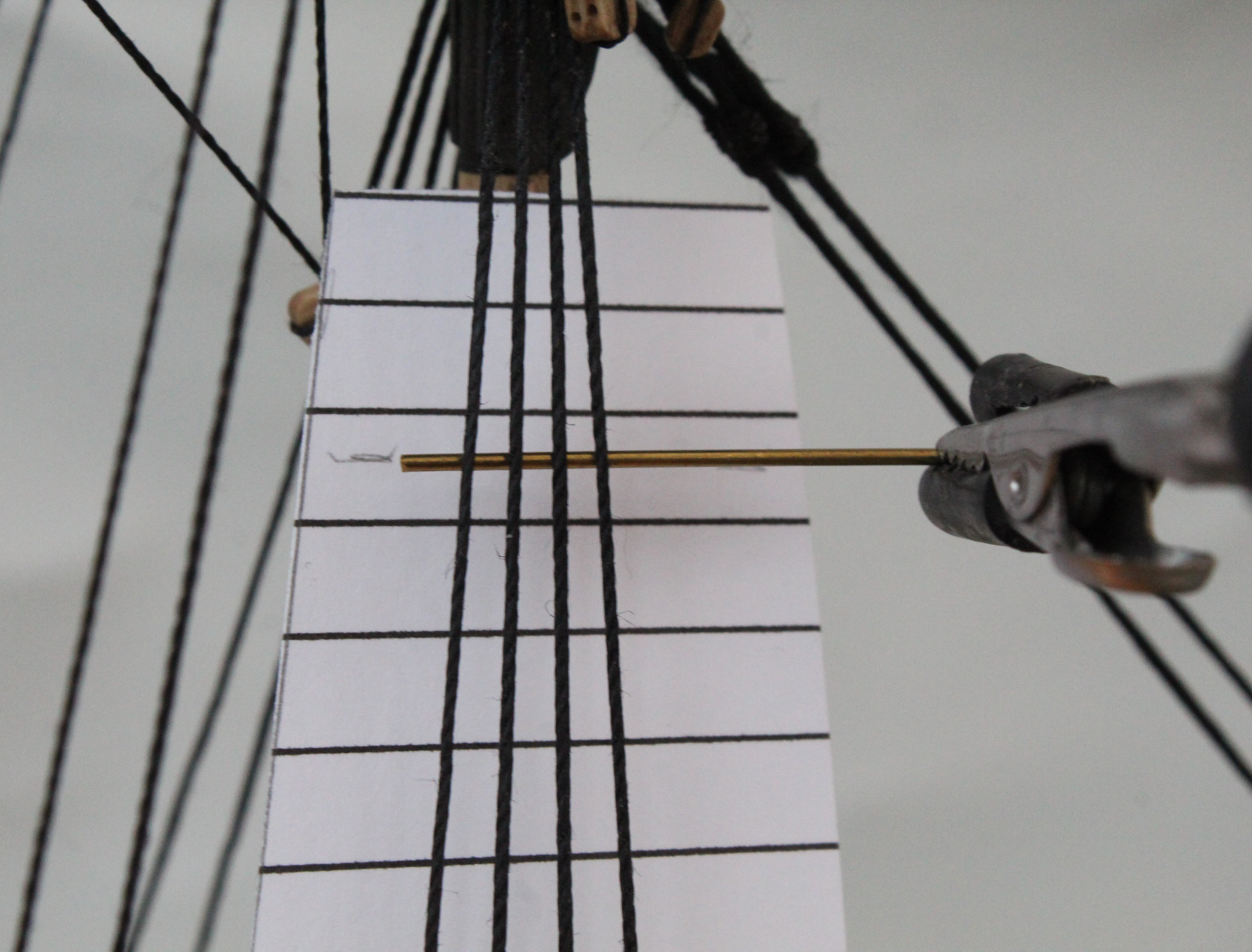
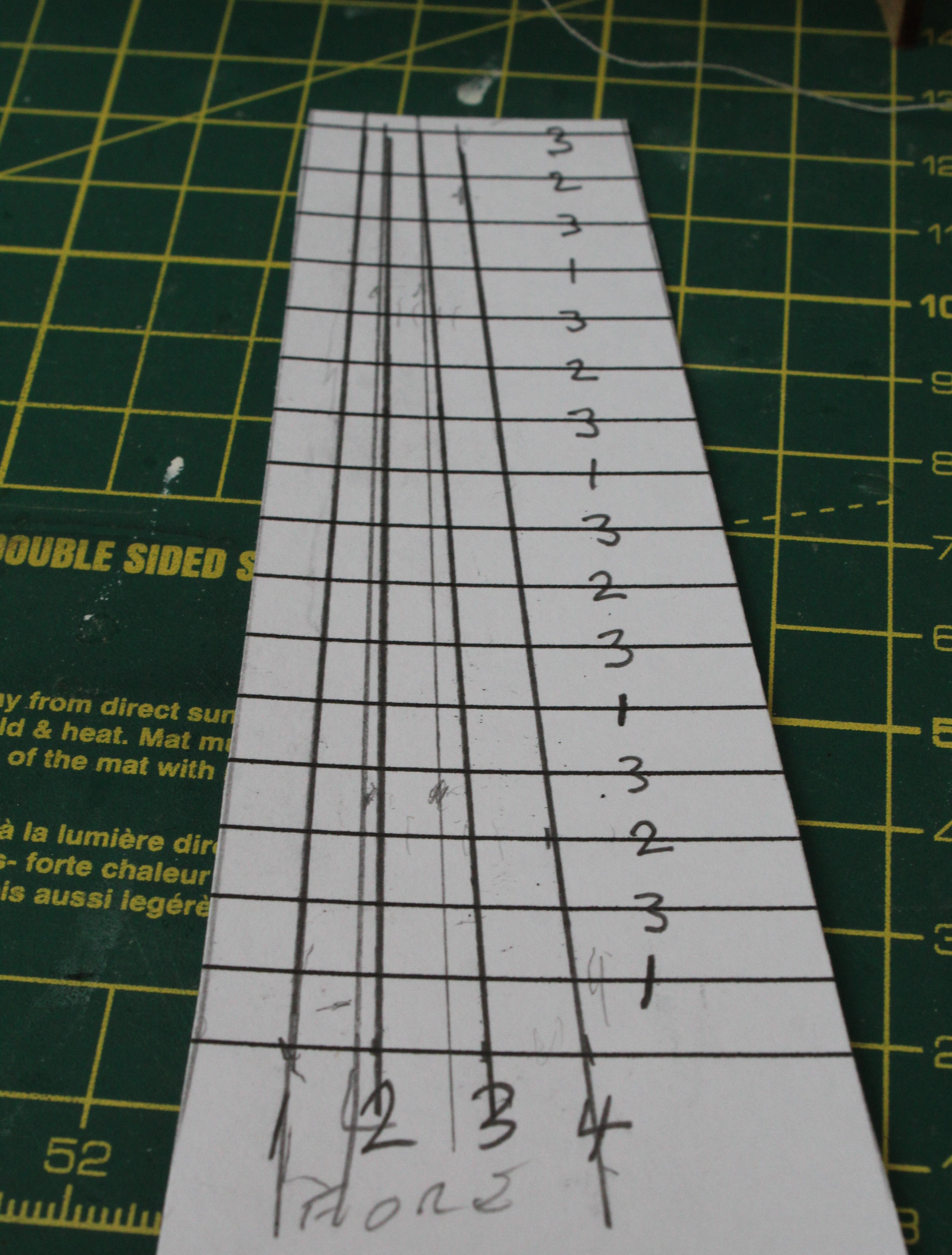
The next task was to add the ratlines. I used a template for this.

I added the ratlines above the stave first.

I did mark the template to help with the positioning. When adding the ratlines added all the 1's followed by all the 2’s and then finally all the 3’s.


The final task is to add the futtock shrouds, these have been prepared and are ready to be installed.

-
Date: 05/11/2024
Time worked today: 4 hours.
Total time spent on build: 120 hours.
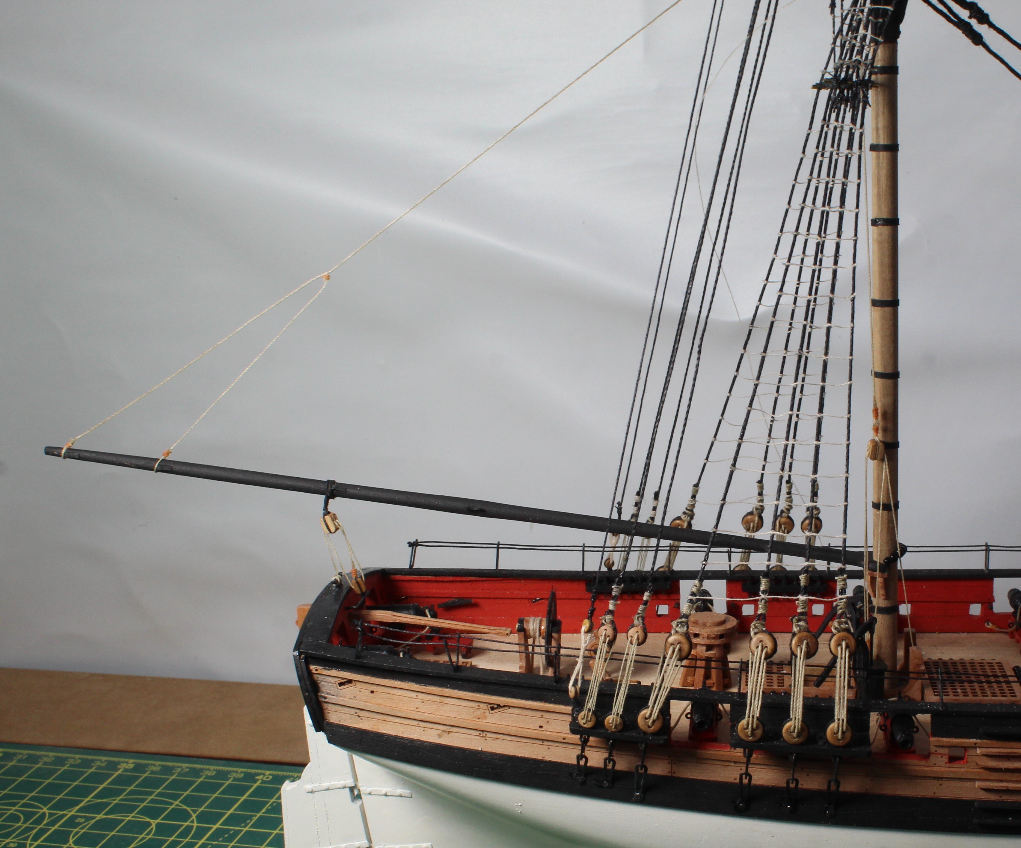
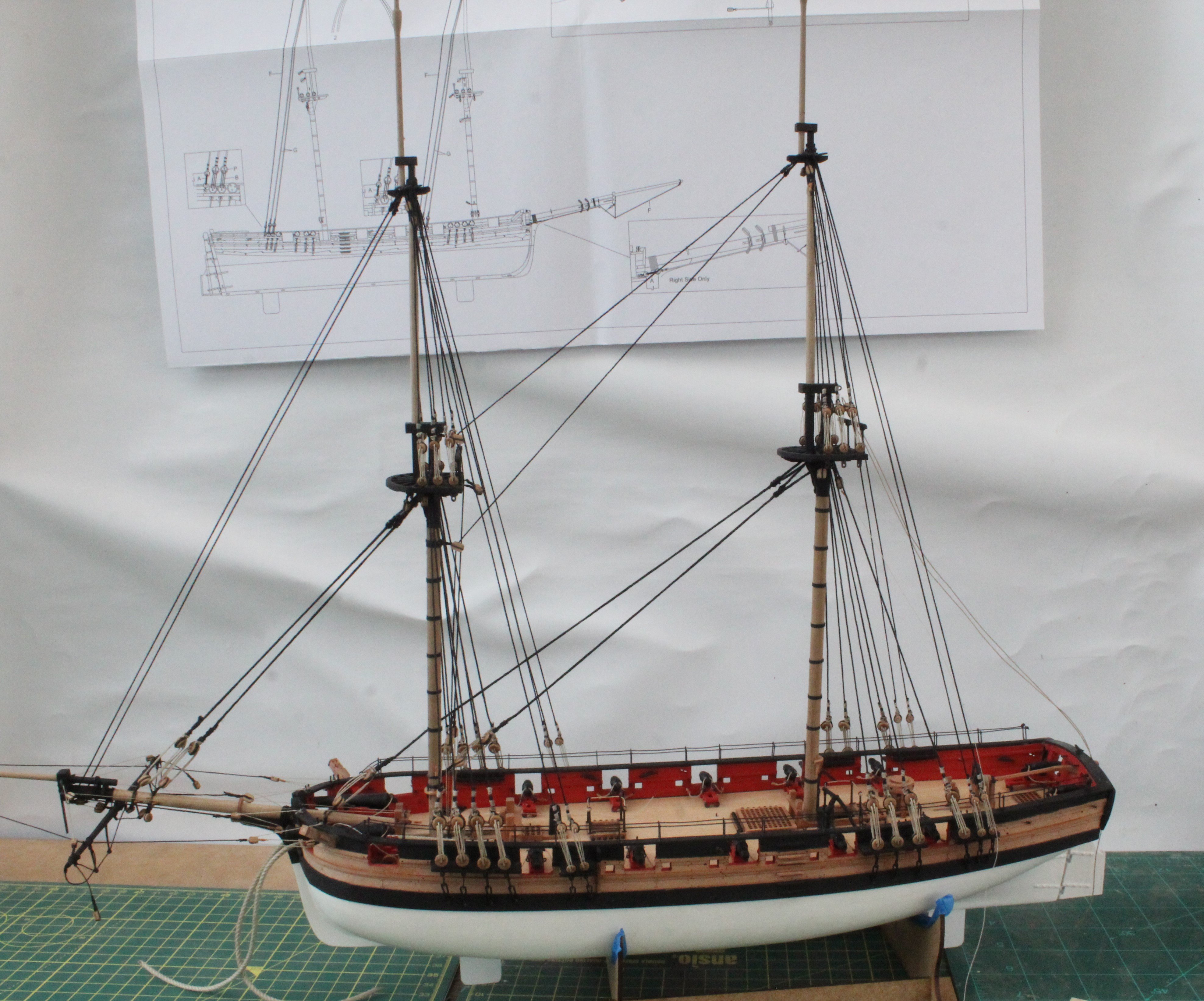
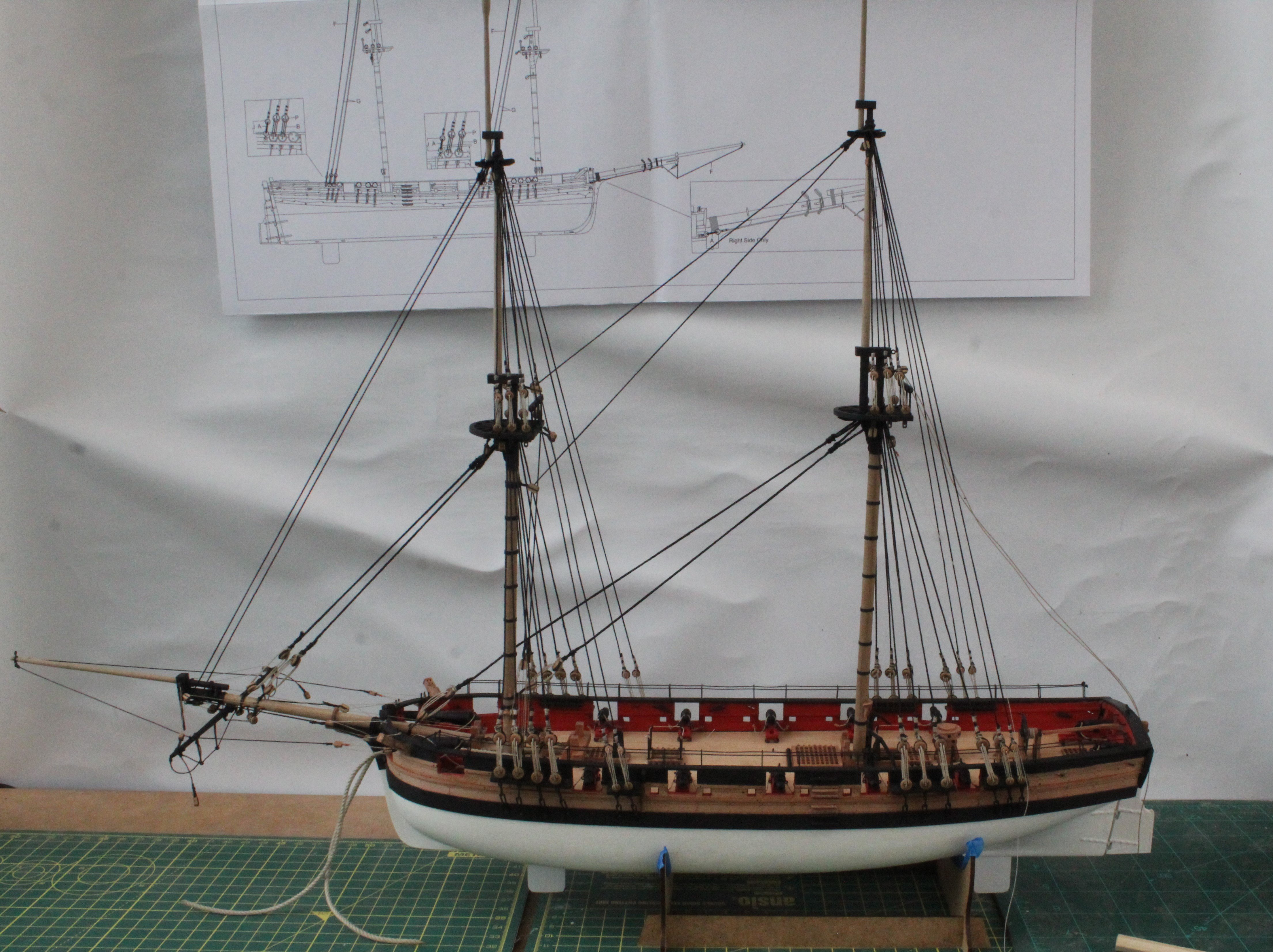
Topsail Stays
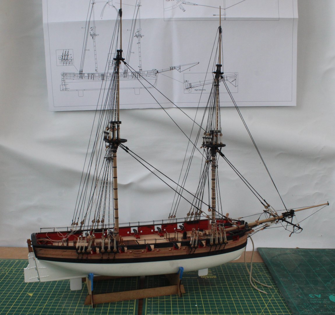
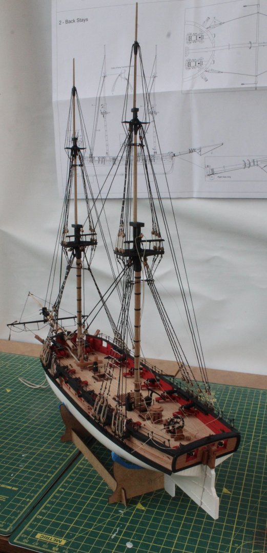
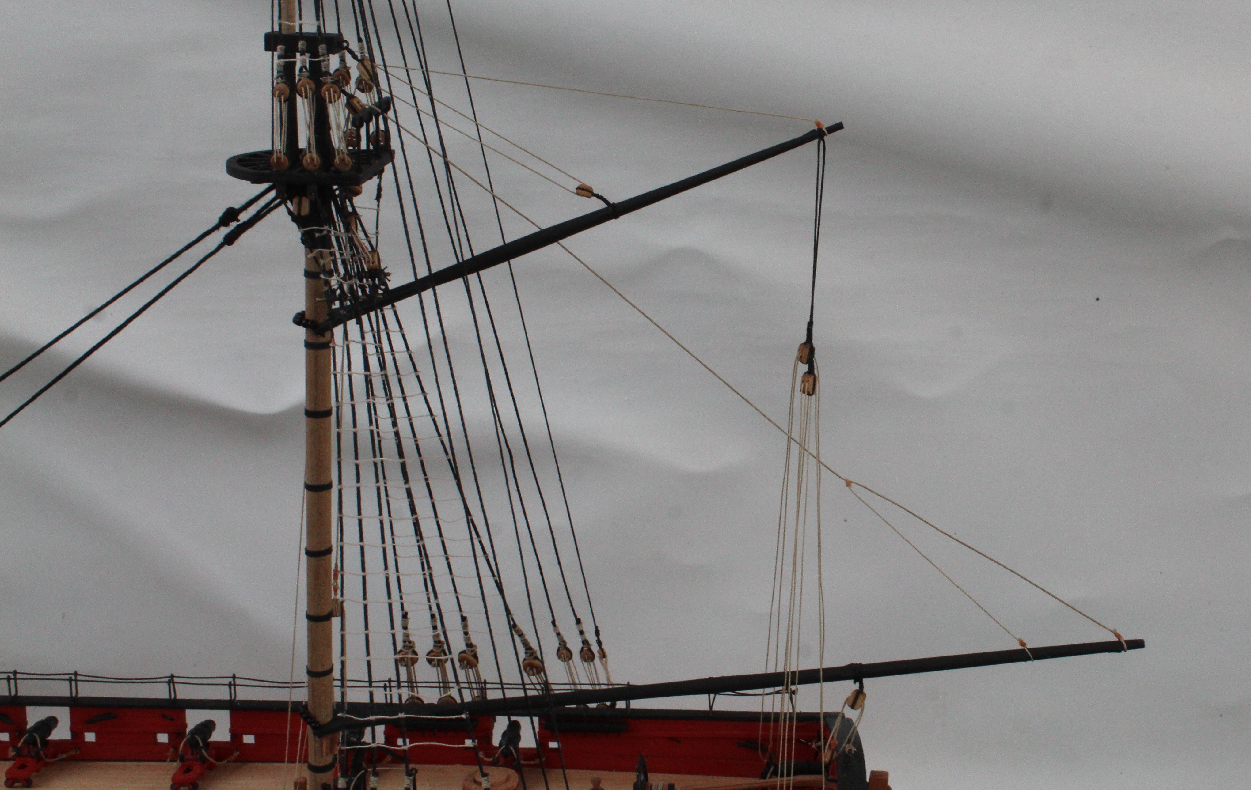
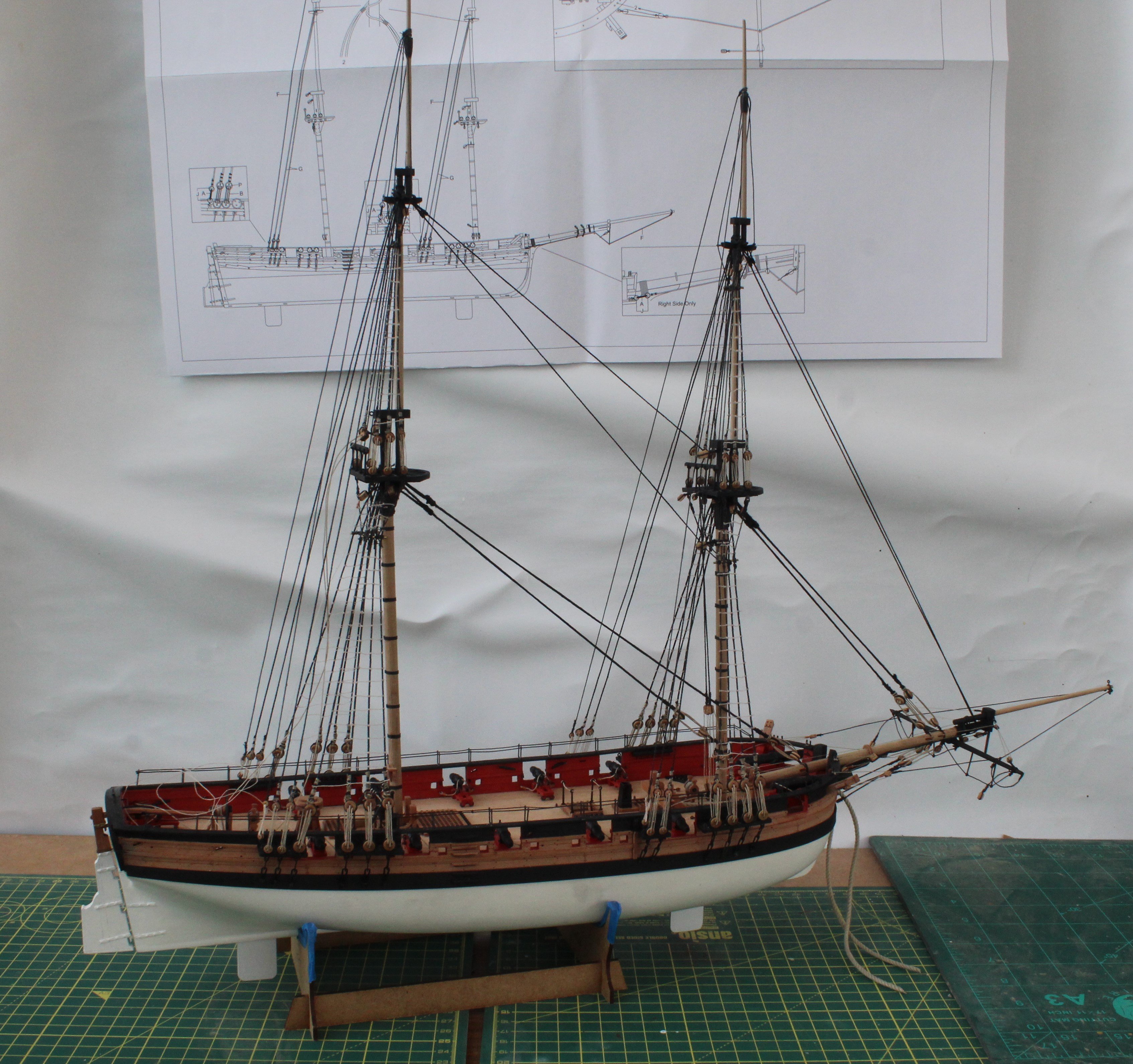
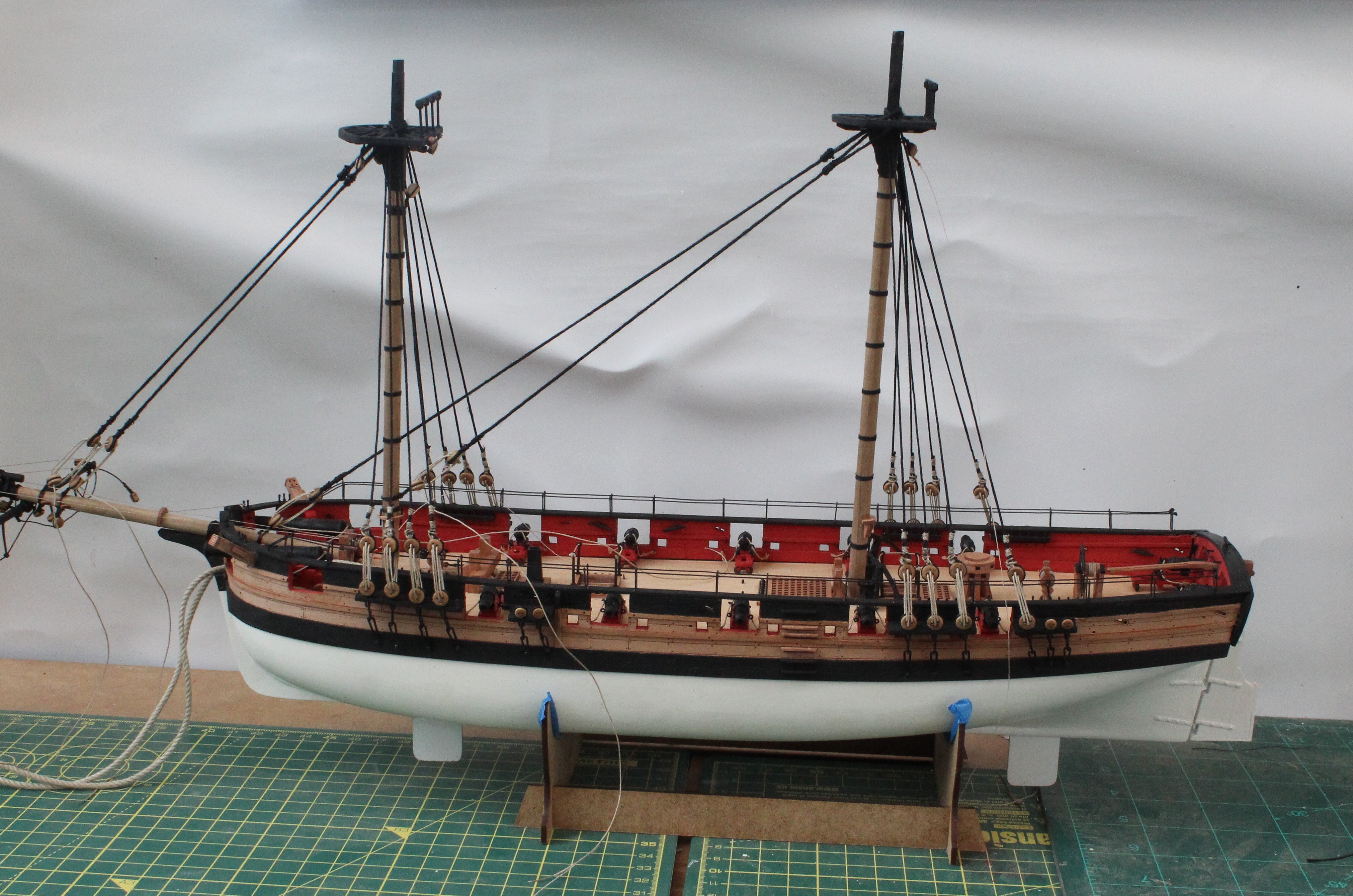
To start this post I have attached a photo showing the current build status of my adder.

I have now added the topsail mast stays and the back stays.
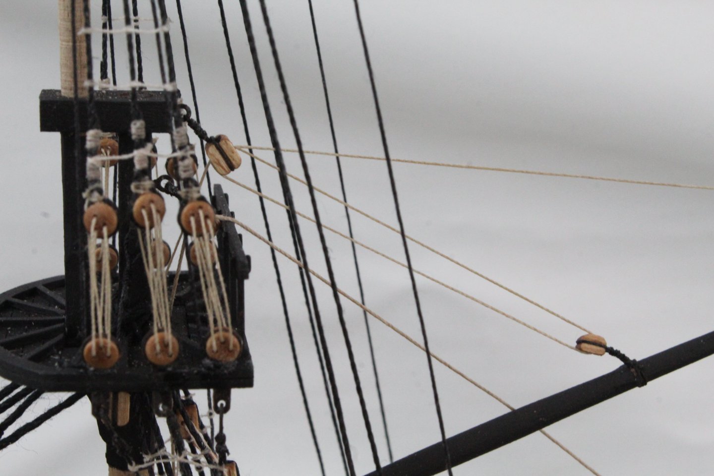
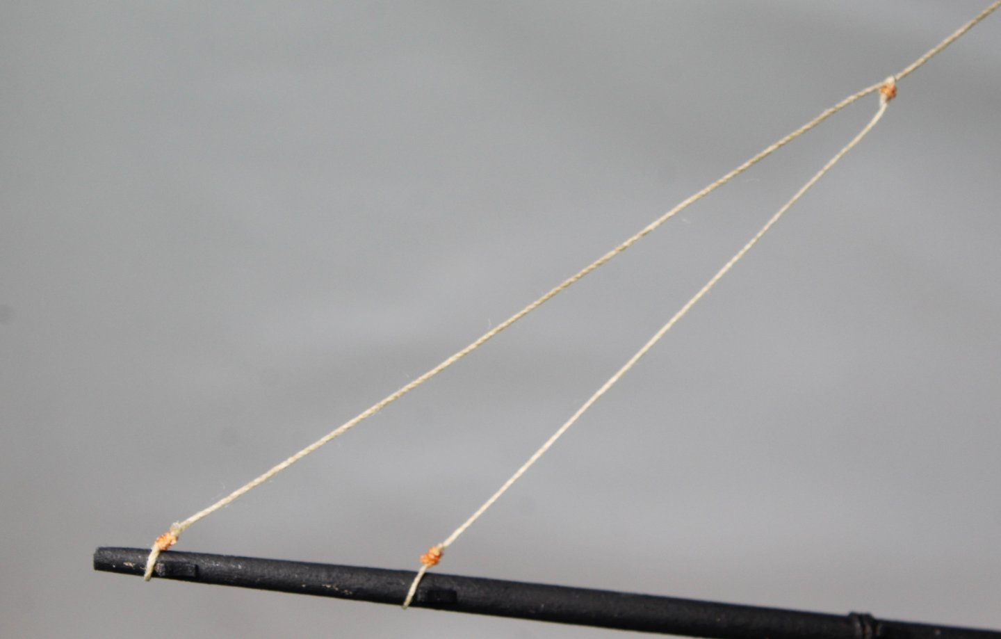
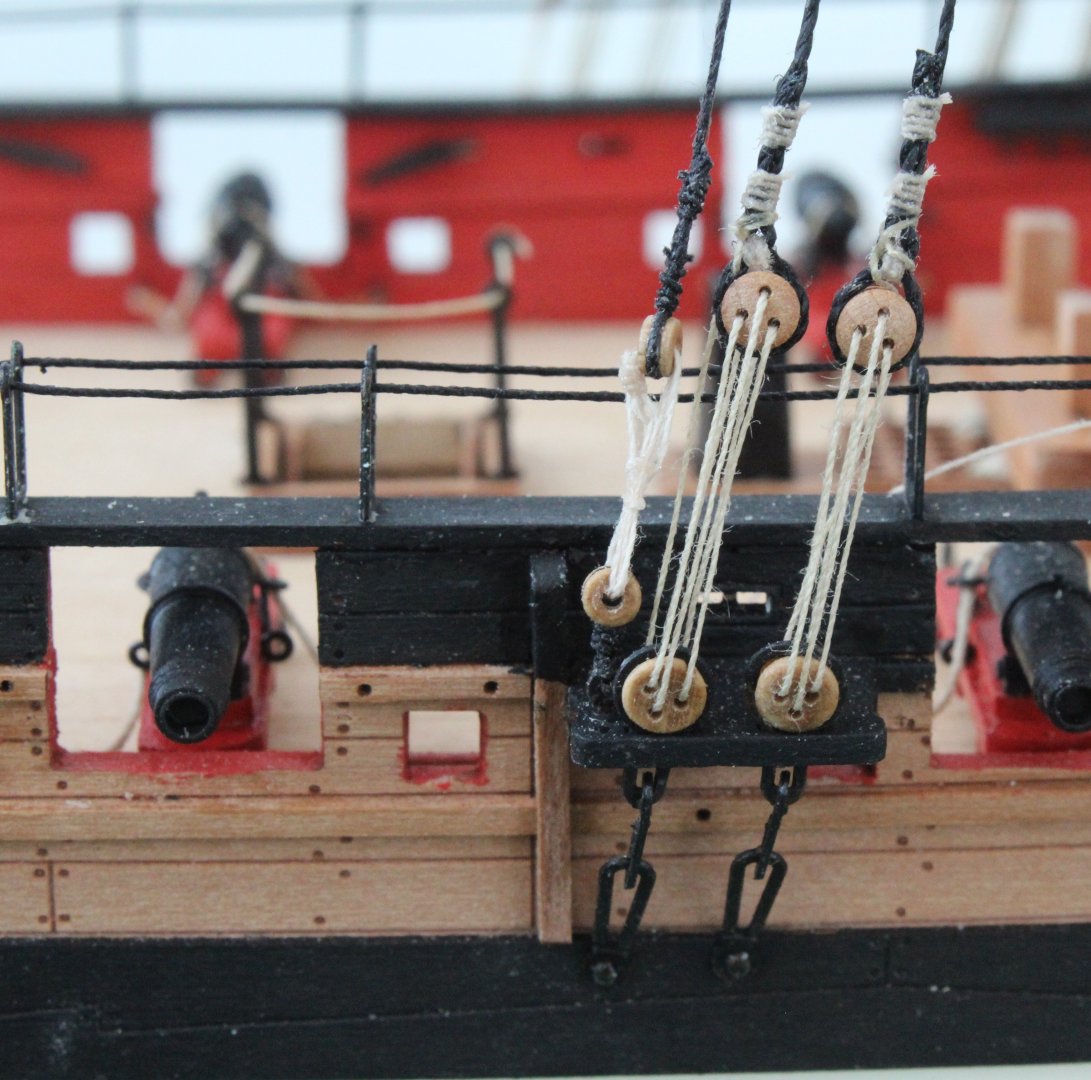
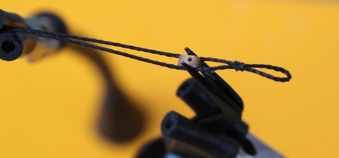
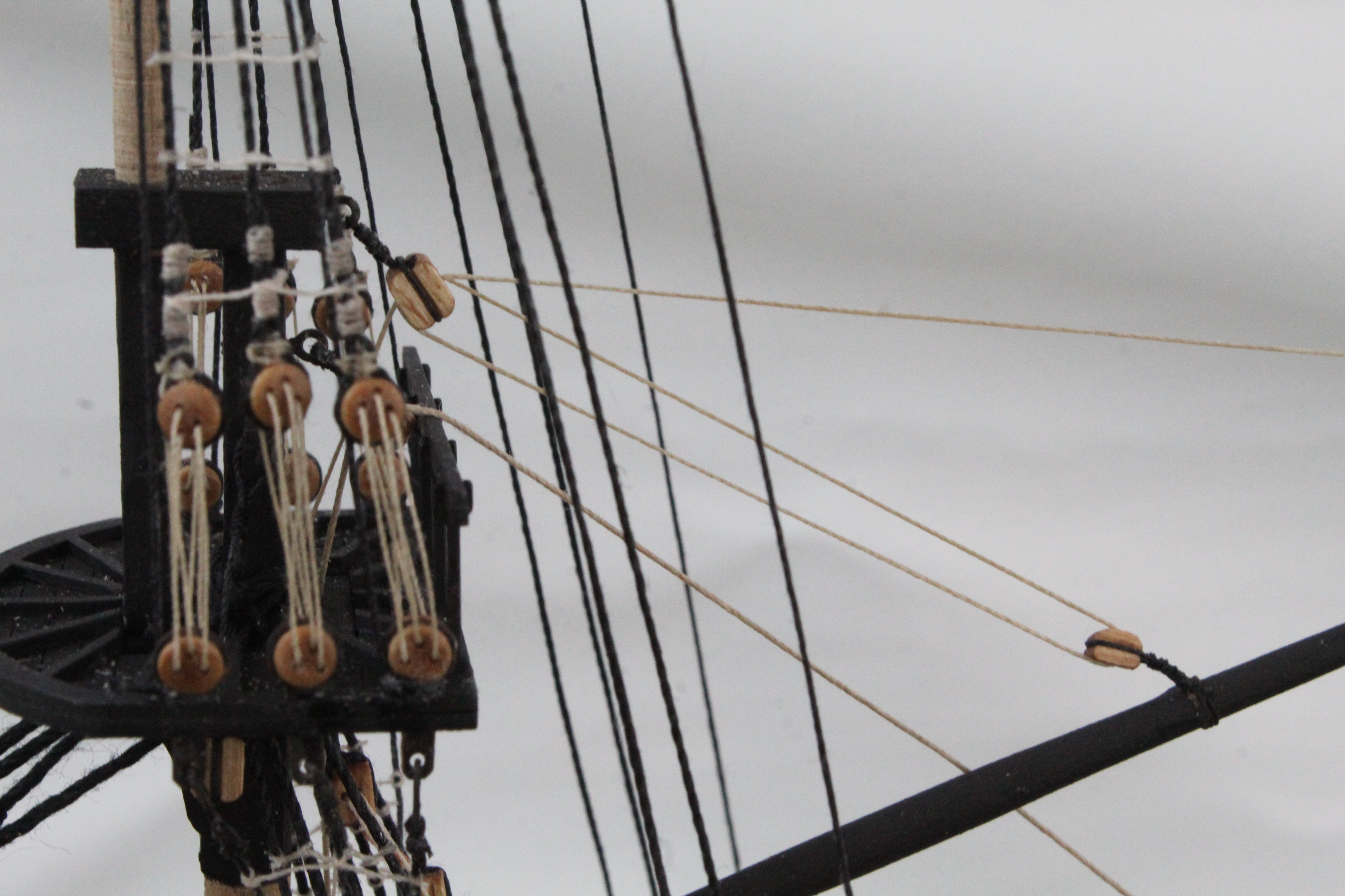
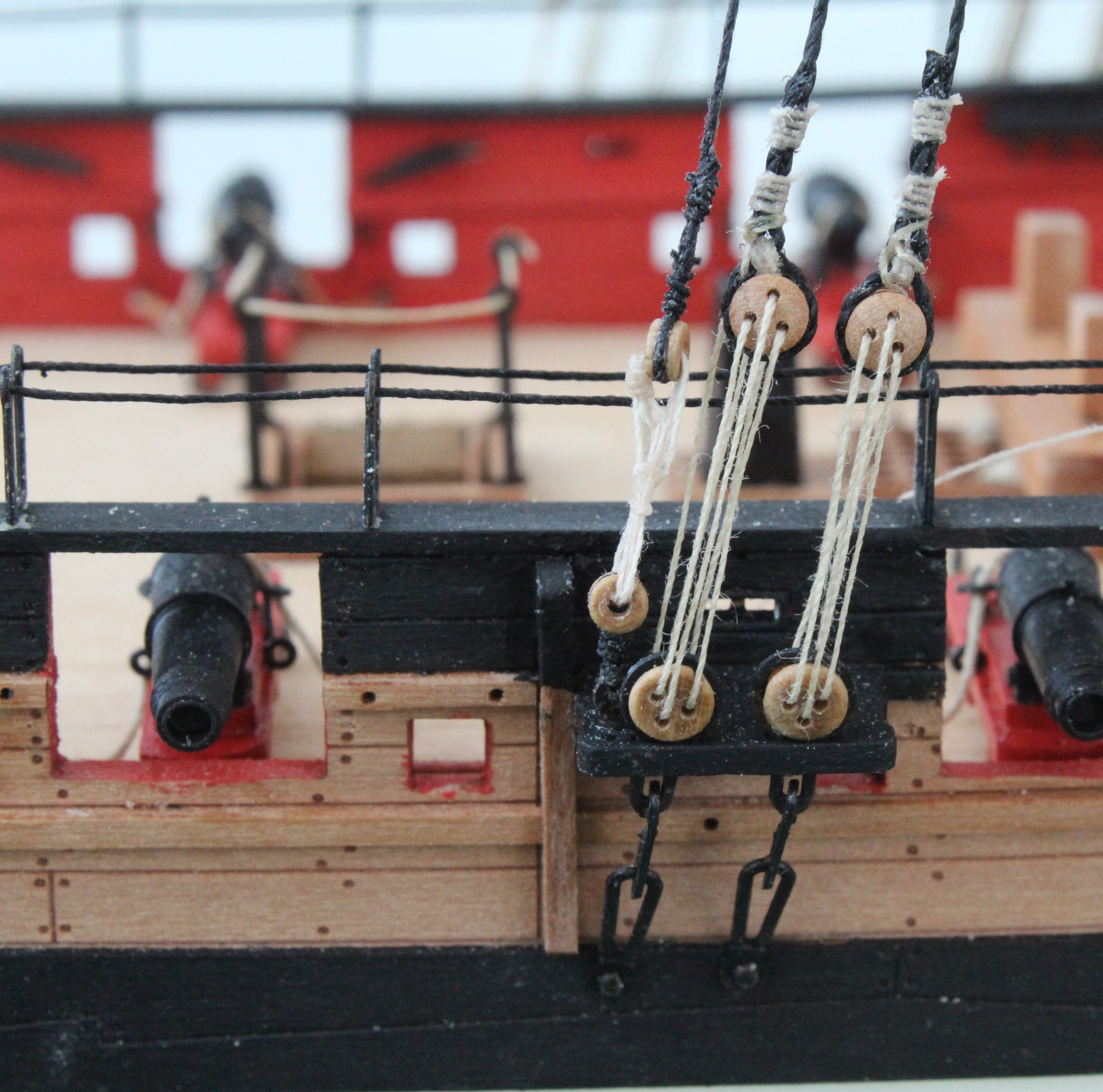
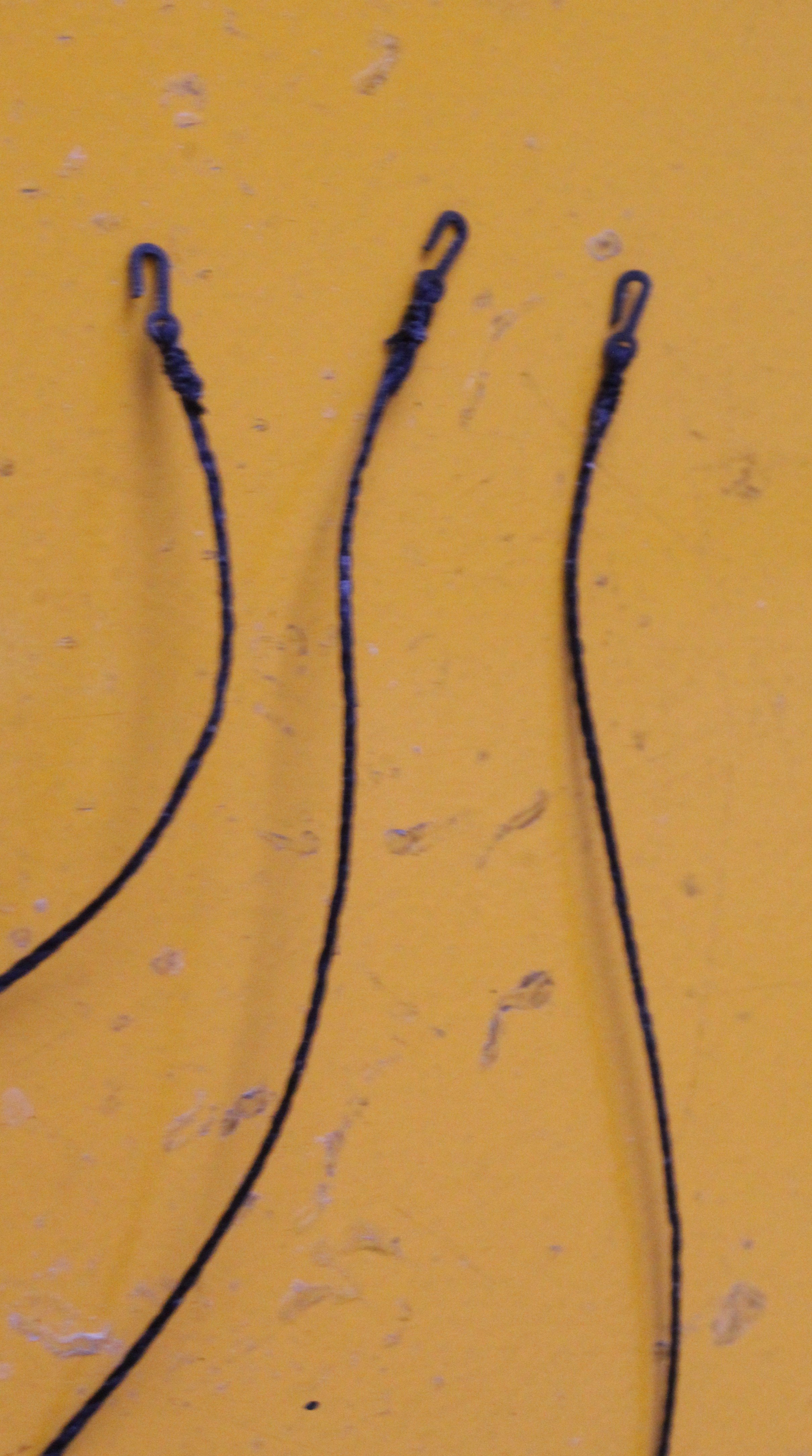
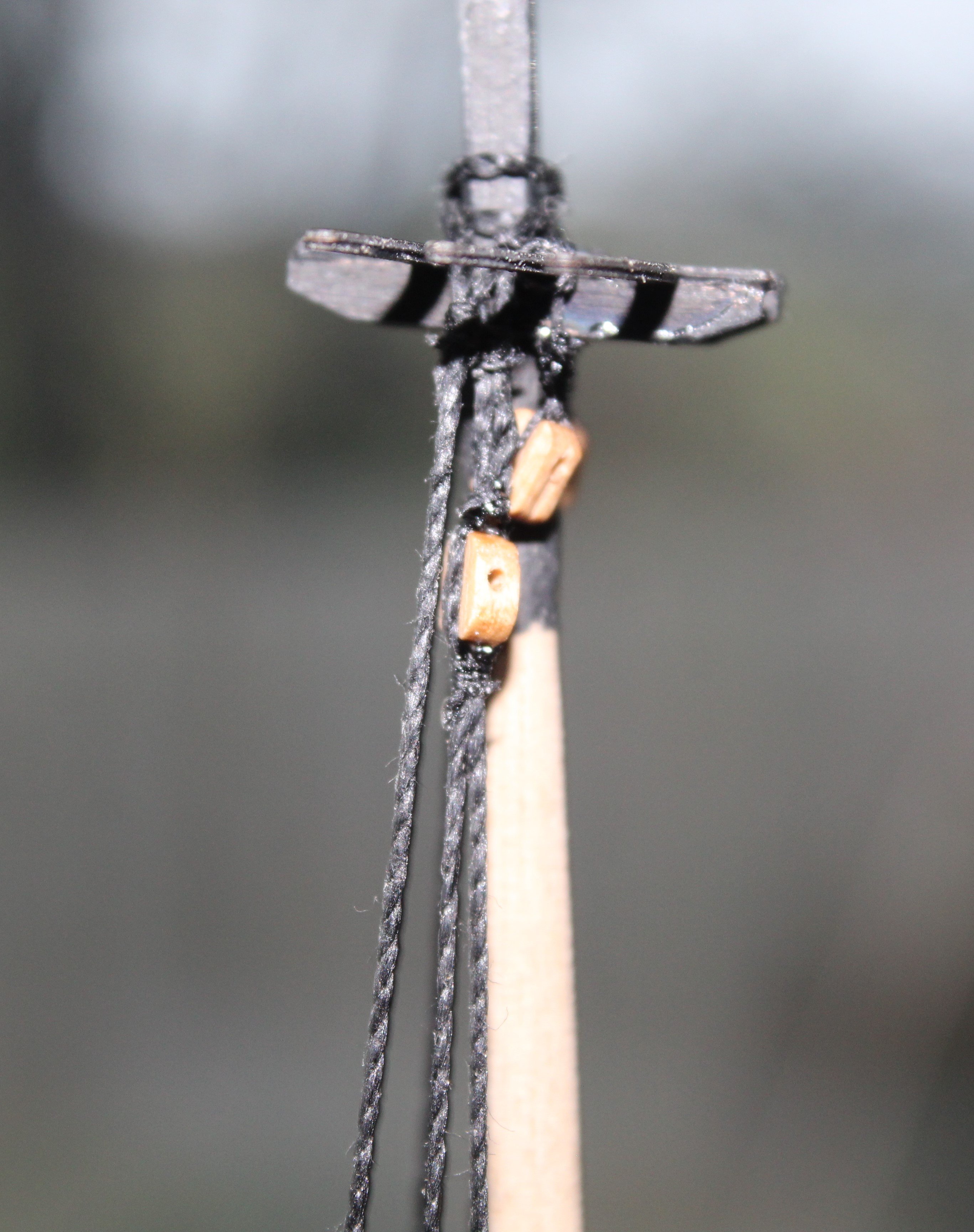
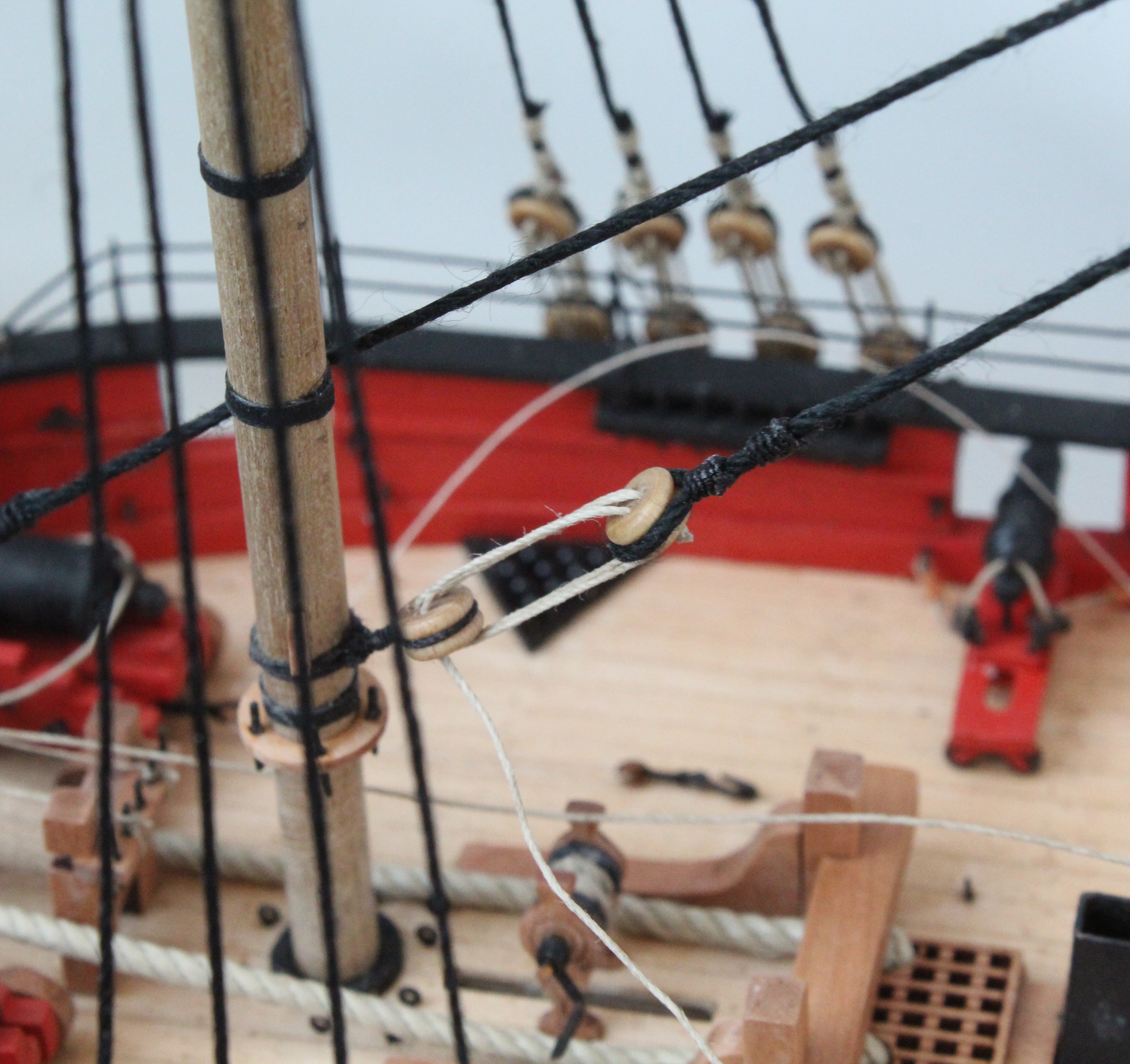
The topsail stays are belayed to the deck via a two block arrangement. The lower block is a single block secured to the deck (main) and hull (fore) via an eyebolt. The inter-block rigging is added to these blocks via an thimble. A double block is added to the end of the stays.
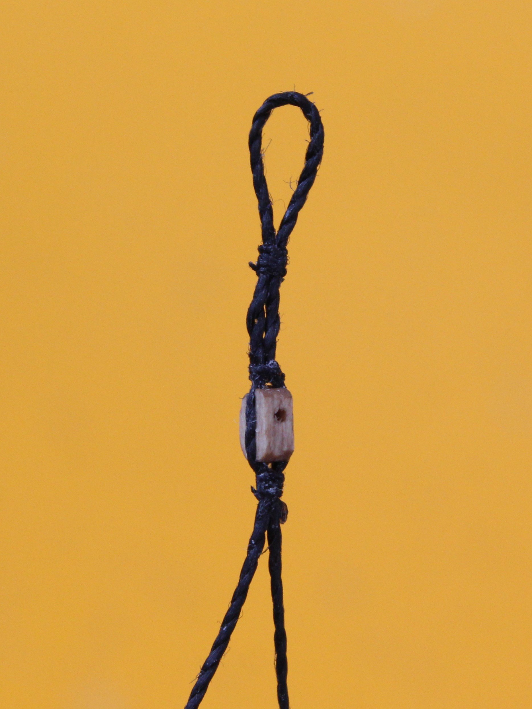
I started the process by adding the double block to each of the stays. To do this I make a loop in the stay.

The loop is then closed around the block and its position can be adjusted up or down the stay as necessary. As can be seen in the next photo I am checking the position which is just about where I want it to be.

Once I was happy with the positioning of the block a second set of seizing was then added.

Once that was done the single blocks were seized to the eyebolts and then secured to the deck / hull. Adding and belaying the inter-block rigging was then a straightforward task.

The belaying of the main and fore mast stays have also been completed.

And finally another photo of the Adder

I will now start work on adding the topgallant masts and shrouds.

-
Build Update
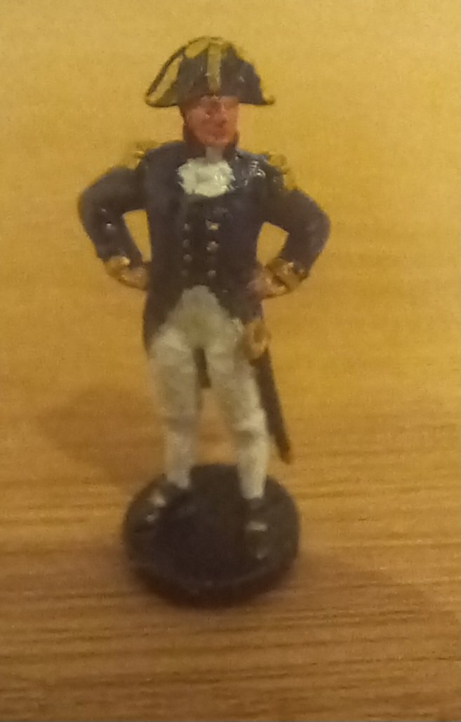
I have had an enforced 3 week break from building this model. It started when I had an offer to sell my model of the Indy. I took a few days to dust her down and to build a suitable shipping frame. I also hand painted the figure of Captain Pellow.
Unfortunately she suffered some damage when the buyer tried to fit her in his car,. It then took me a week to repair the damage, which required two new topgallant masts (Main and Fore) and then removing and then replacing all the topgallant mast and yard rigging.
I also had a weeks holiday in France in the middle of all of this mayhem.
The repaired Indy has now been delivered to the buyer intact, using a specialist delivery company (Lenspeed).
Therefore today I was finally able to return to the Adder build and I will be able to start posting my progress later this week.
- chris watton, ECK, Craigie65 and 2 others
-
5
-
-
14 minutes ago, Ronald-V said:
Congratulations on the sale! I can imagine that at some point you have to sell models because there is simply no more room for them, especially this one! But it will indeed hurt a little bit, because you have put so much time and energy into it. Especially if it is gone so soon!
Sad to see her go, but I had no room for her and happy that she has gone to a place to be displayed.
- Ronald-V, Ryland Craze, mtaylor and 1 other
-
4
-
2 minutes ago, James H said:
That was a hell of a save!
Congrats on the sale too. Well deserved.
Many thanks, once I had managed to release the remaining bits of the damaged masts from the caps I was able to work methodically to redo the rigging. The hardest task was to remove the topgallant shrouds from the belaying points.
- mtaylor, Ryland Craze, Oboship and 1 other
-
4
-
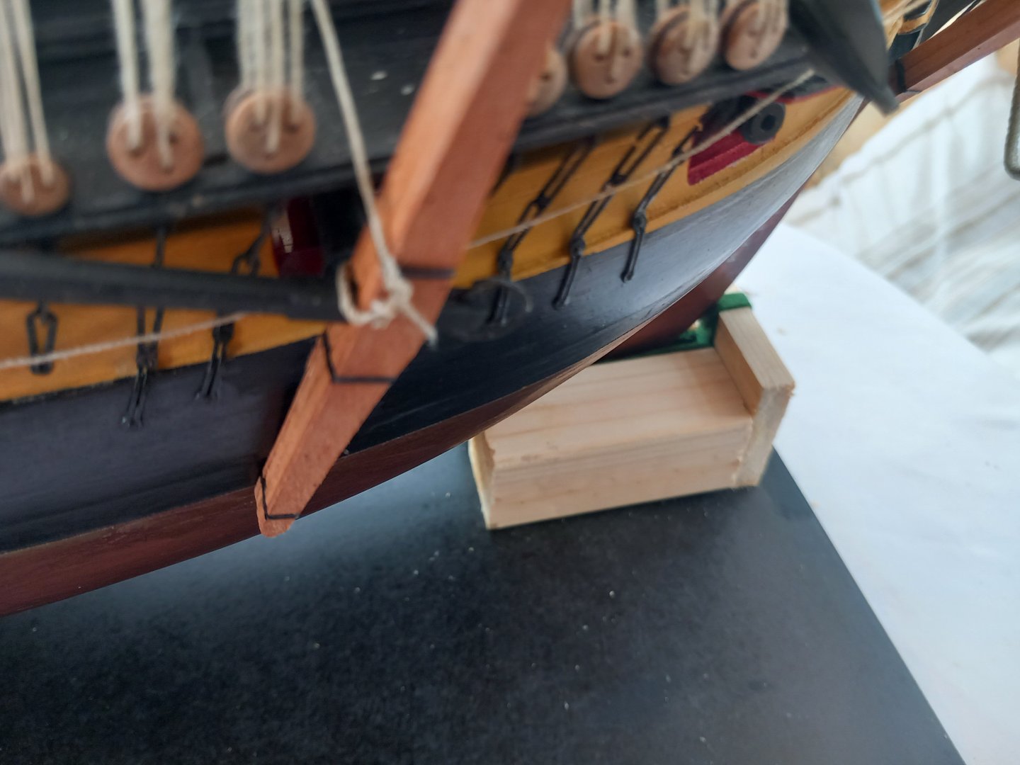
Goodbye To My Indy
I was approached recently to see if I would be interested in selling my Indy. As I did not really have the space for her I was more than happy to let her go.
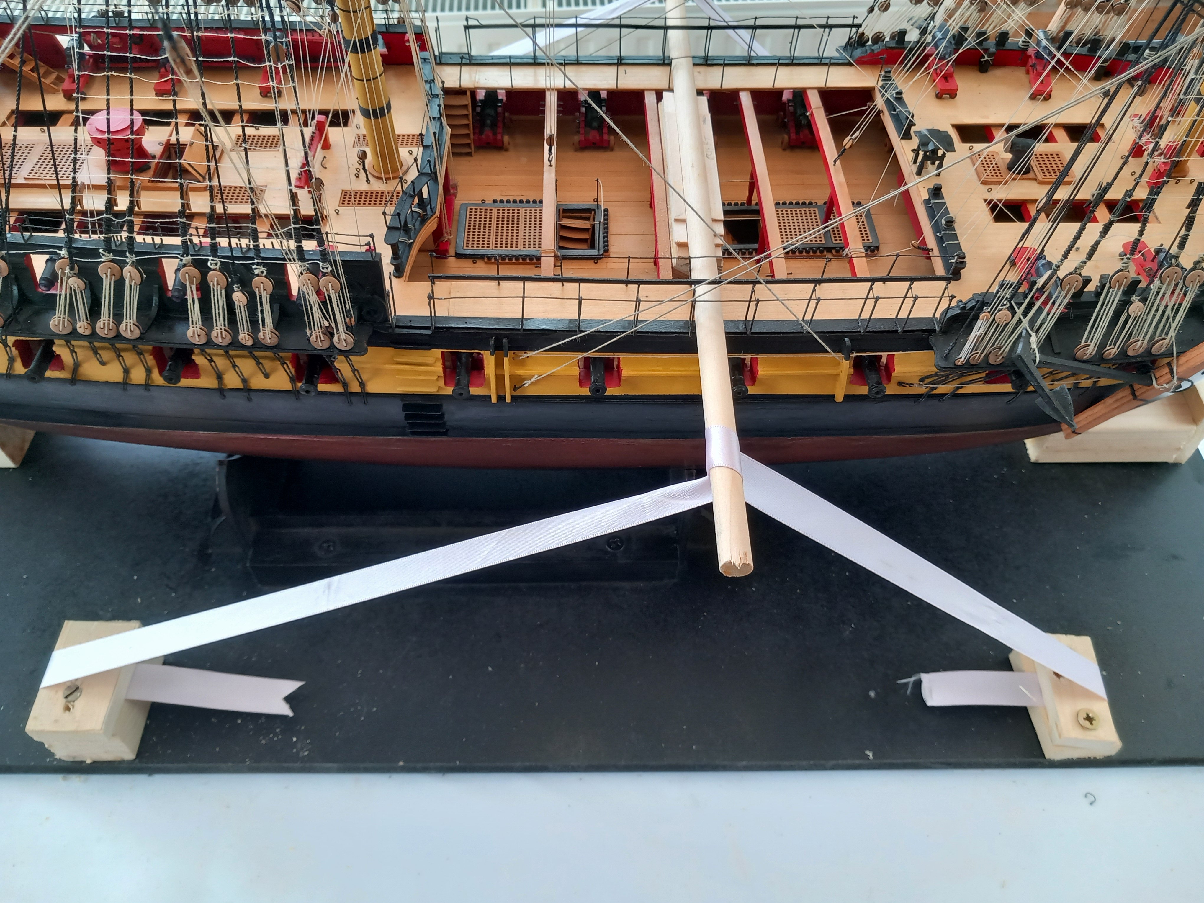
There was not quite enough room in his transport when he came to pick the Indy and sadly the main and fore topgallant mast suffered damage, as can be seen in the photo below. I could have cried and thought a trip to the local tip was on the cards.
He was still very keen to have the model so I set about repairing all the damage. I had to make and fit two new topgallant masts. Next I had to redo all the damaged rigging, such as the shrouds, jeers, lifts, braces, stays, back stays, etc. This was a nightmare to do due to the limited access. After a few days hard work the repairs were complete, and most people will be hard pressed to see the repair.
The Captain looked impressed.
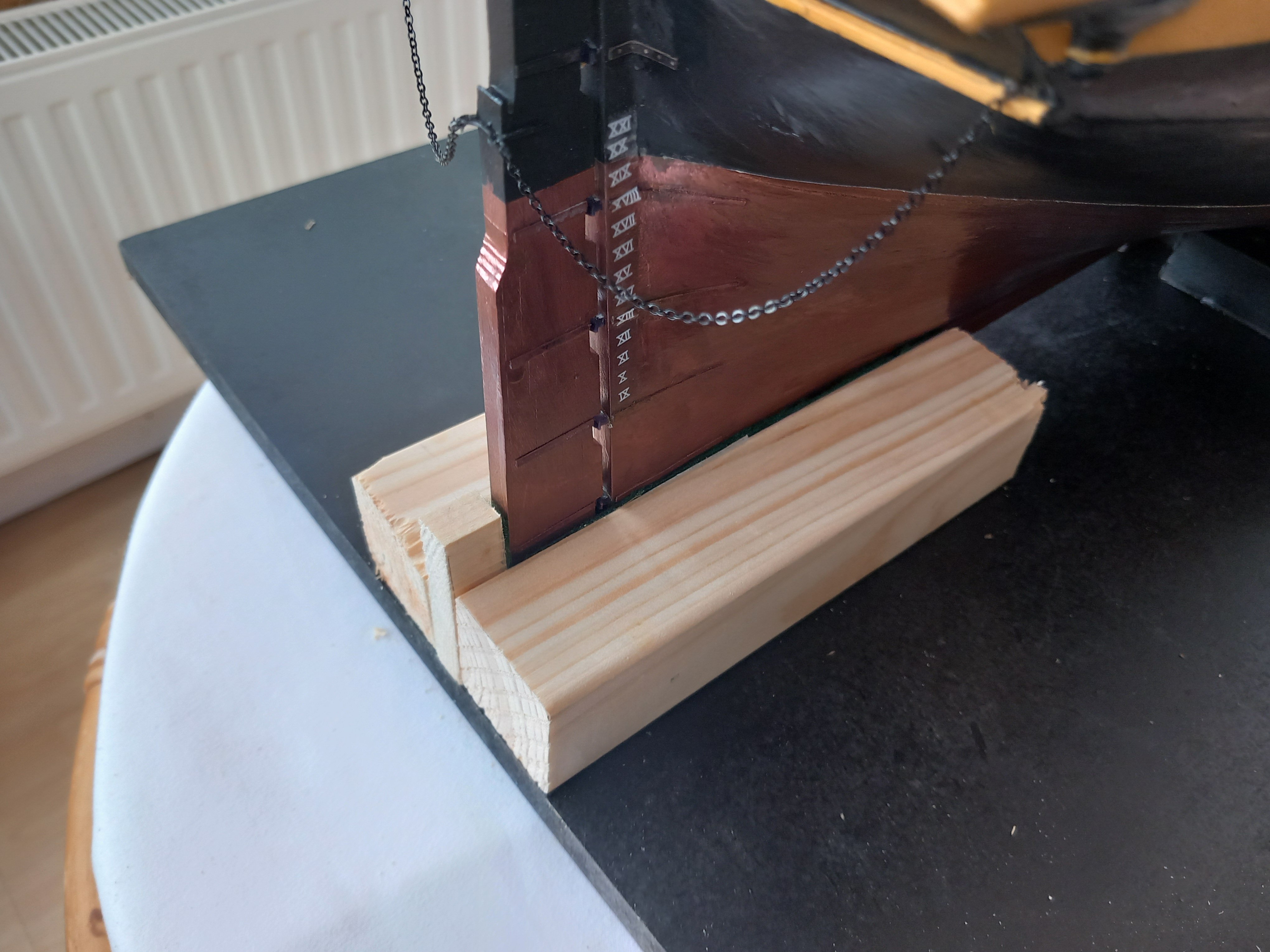
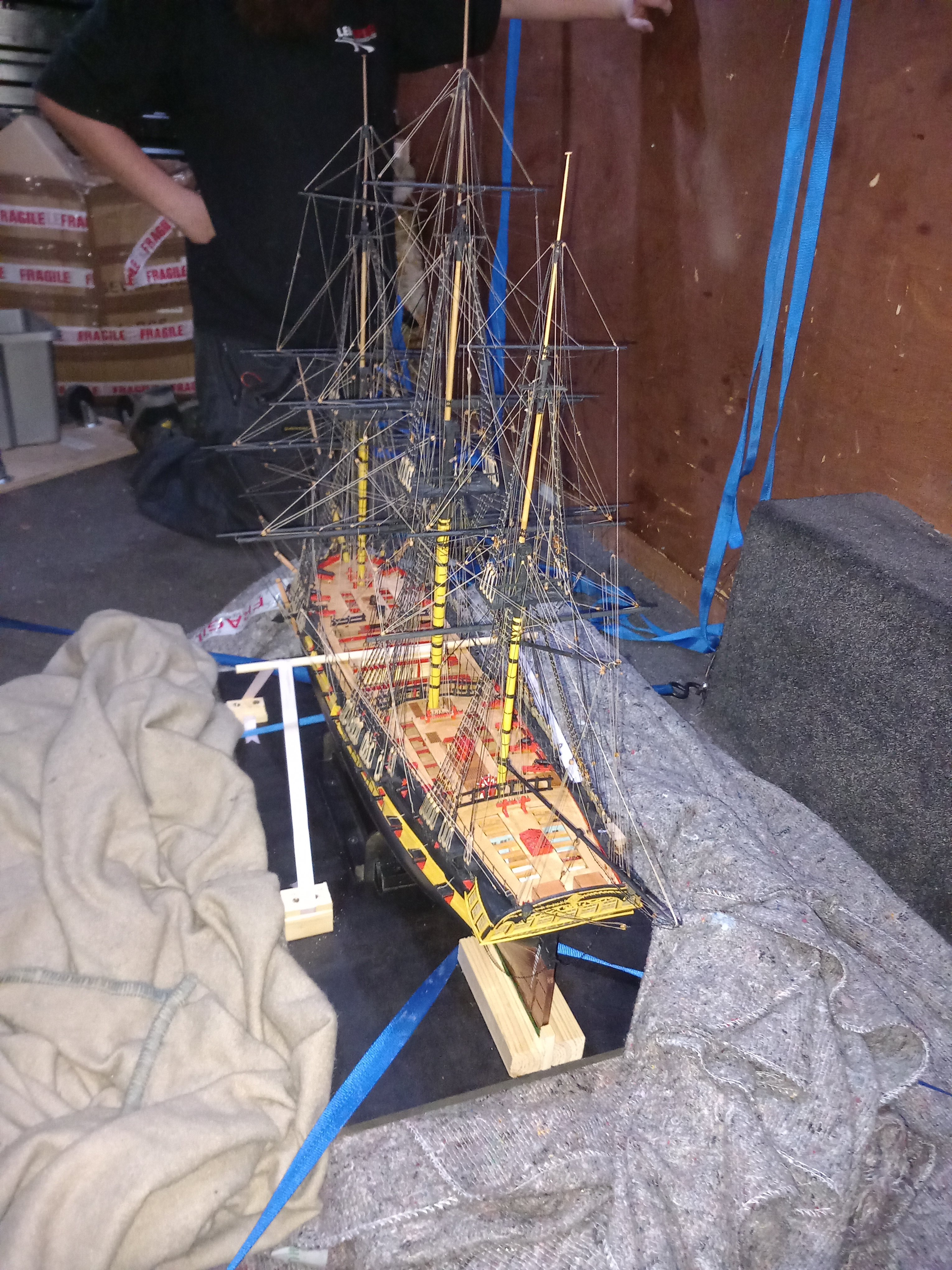
Next I transferred the Indy to a transport shipping frame which should prevent lateral and longitudinal movement. The inner faces of the blocks were felt lined.

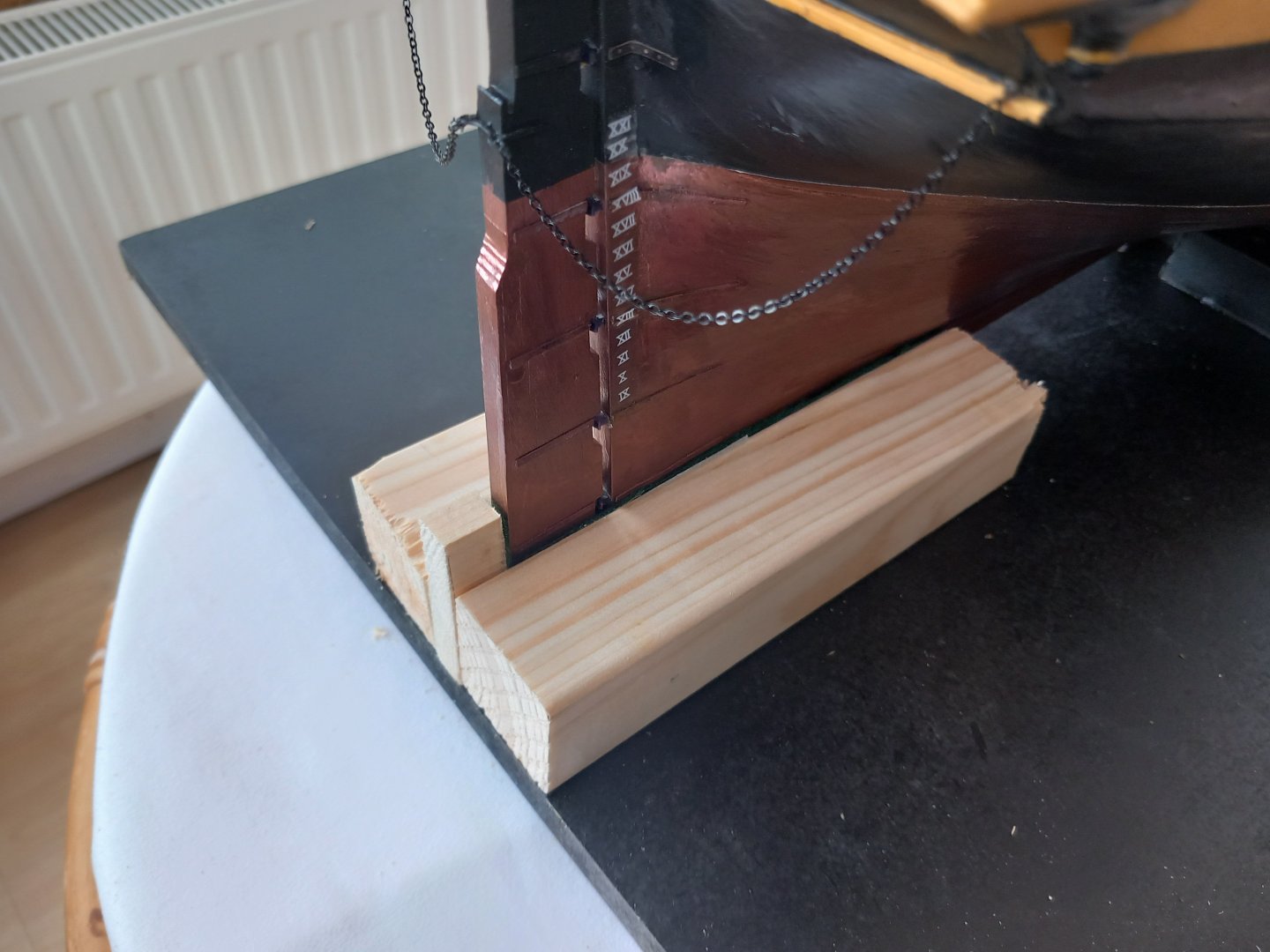
The client then used a specialist transport company, called Lenspeed. They were fantastic, taking great care to load and adding additional damping and strapping to prevent unwanted movement / vibration during the 2 hours drive.
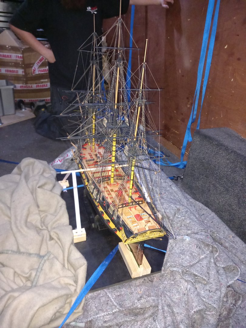
I was a bit sad to see her go, but very happy knowing she has gone to a good home where she will be appreciated.
- Kevin, Knocklouder, DB789 and 10 others
-
13
-
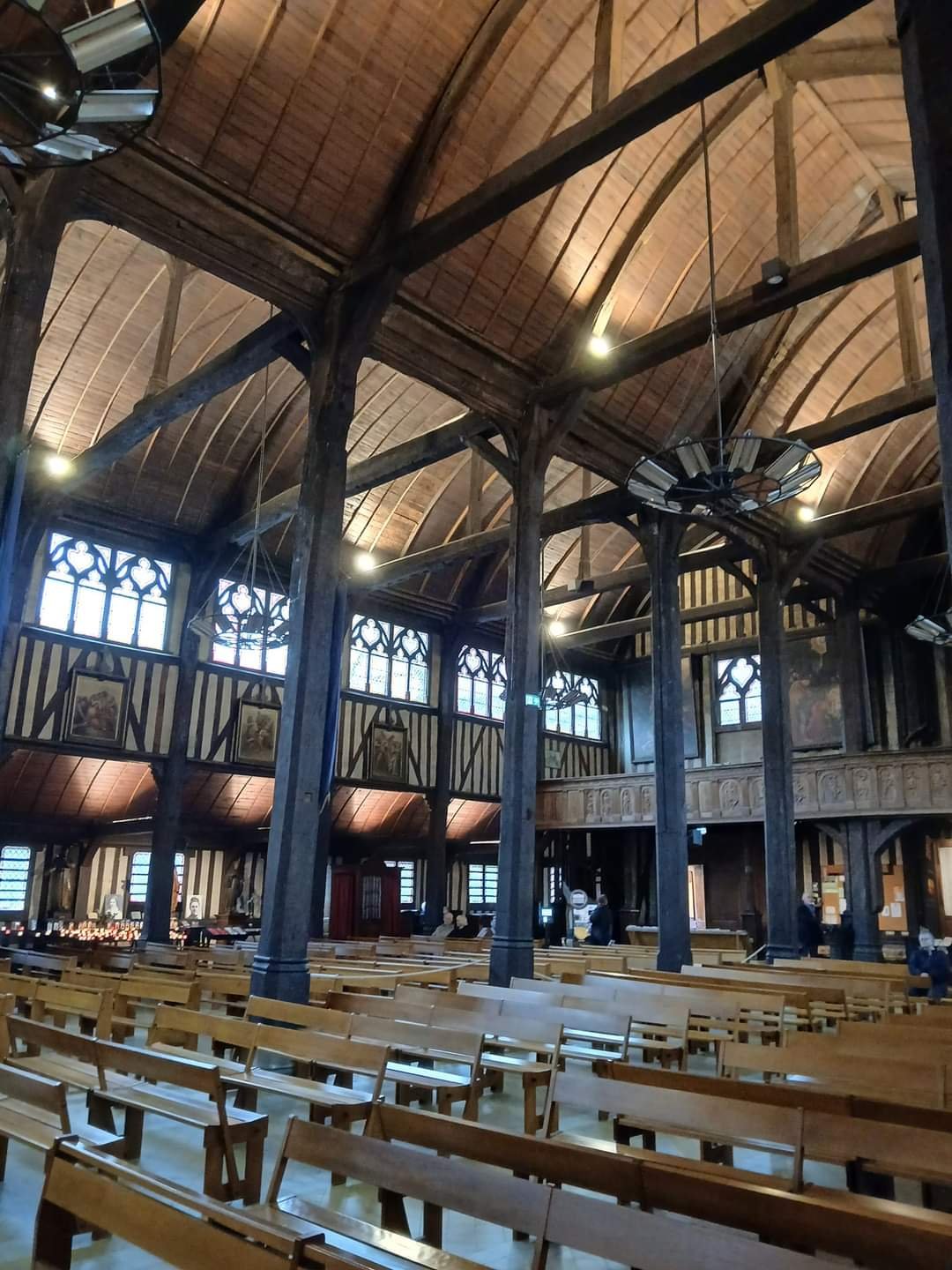
I'm currently enjoying a cruise on the river Seine. Today I visited Honfleur, an old port town used by sailing ships, and discovered a wooden church built by the boat builders. As can be seen in the attached photo the church roof does look like the bottom hull of a ship.

- PaddyO, Oboship, JacquesCousteau and 4 others
-
7
-
Date: 09/10/2024
Time worked today: 4 hours.
Total time spent on build: 116 hours.
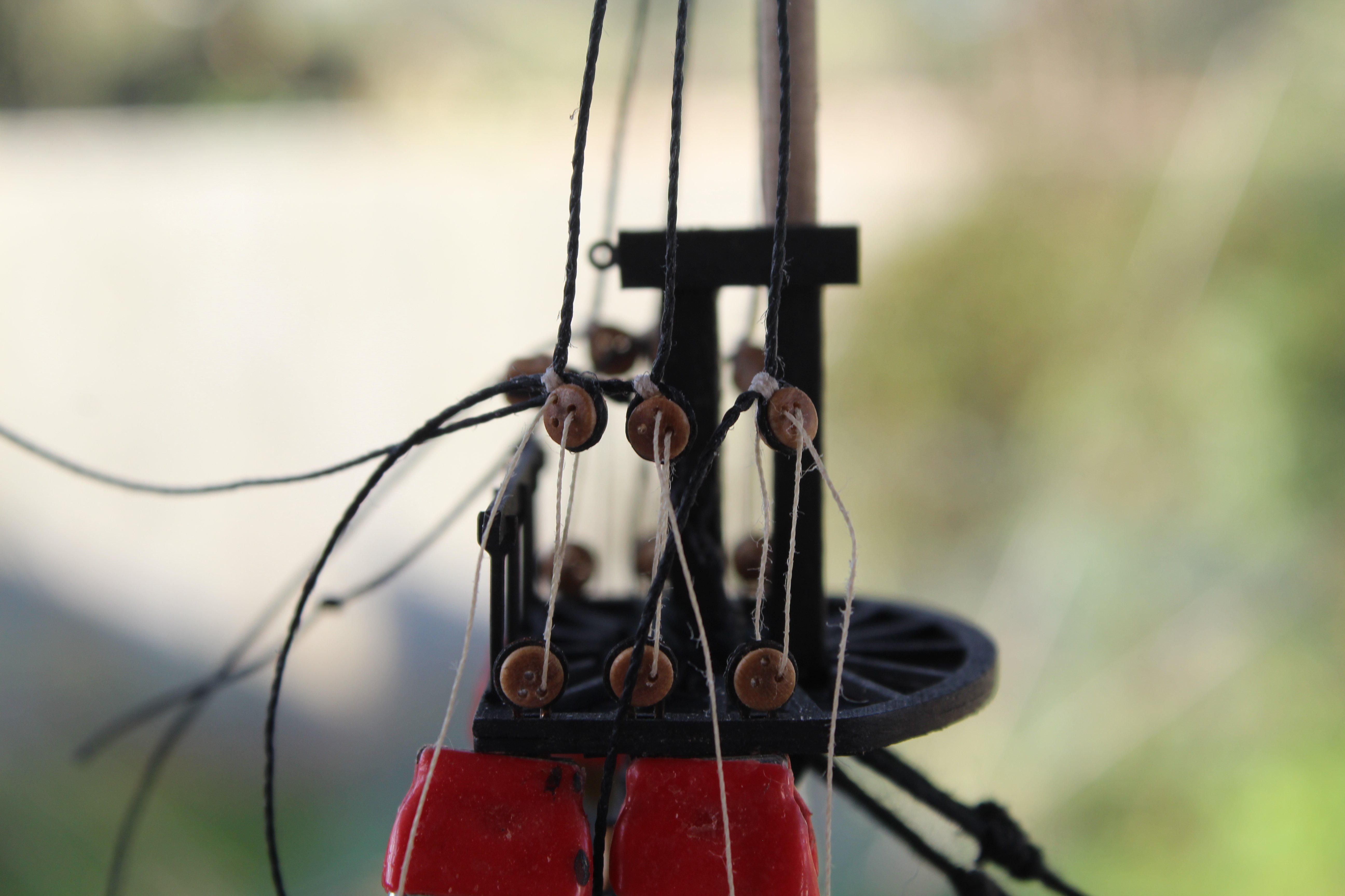
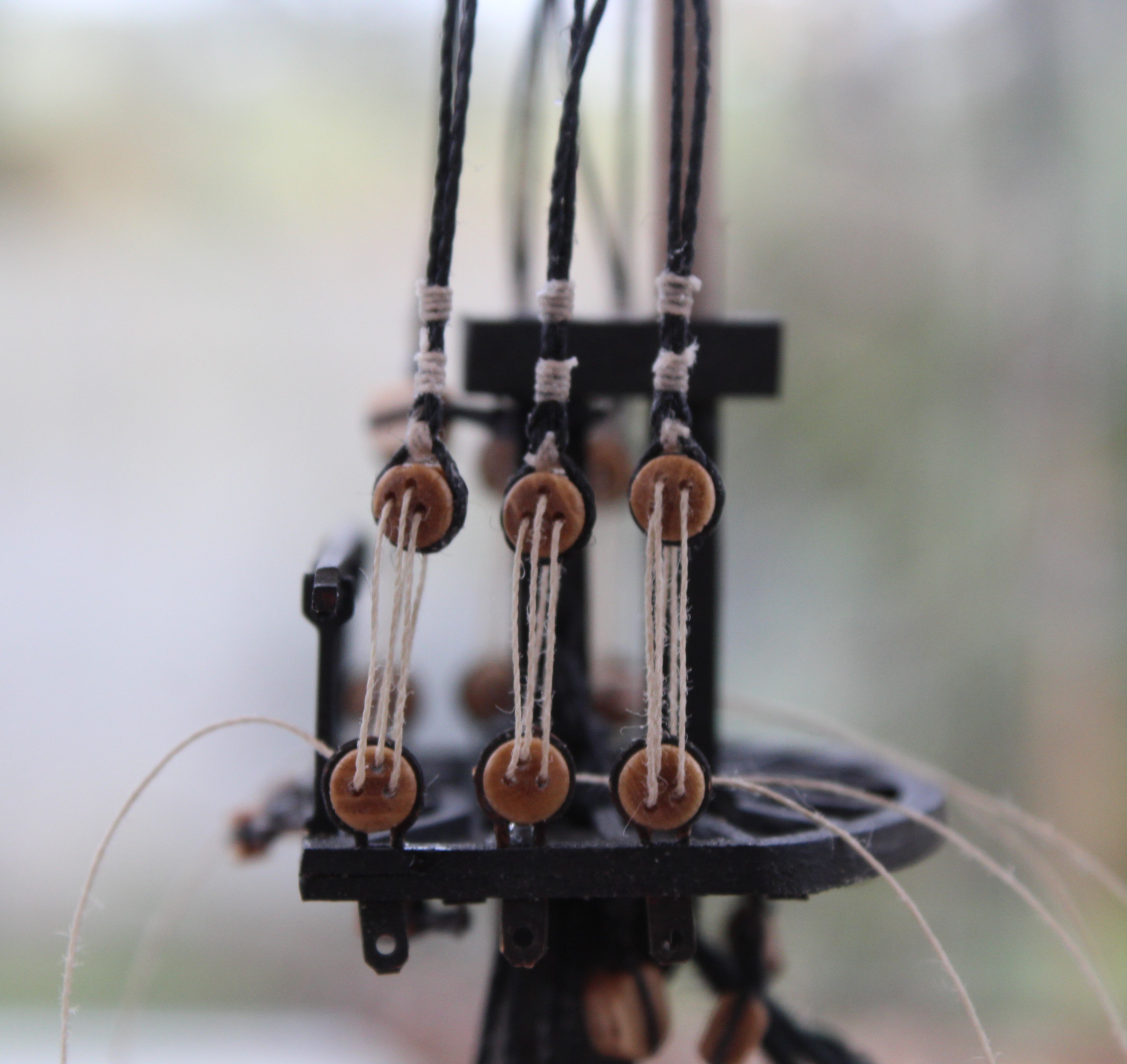
Topsail Mast Shrouds Part 2
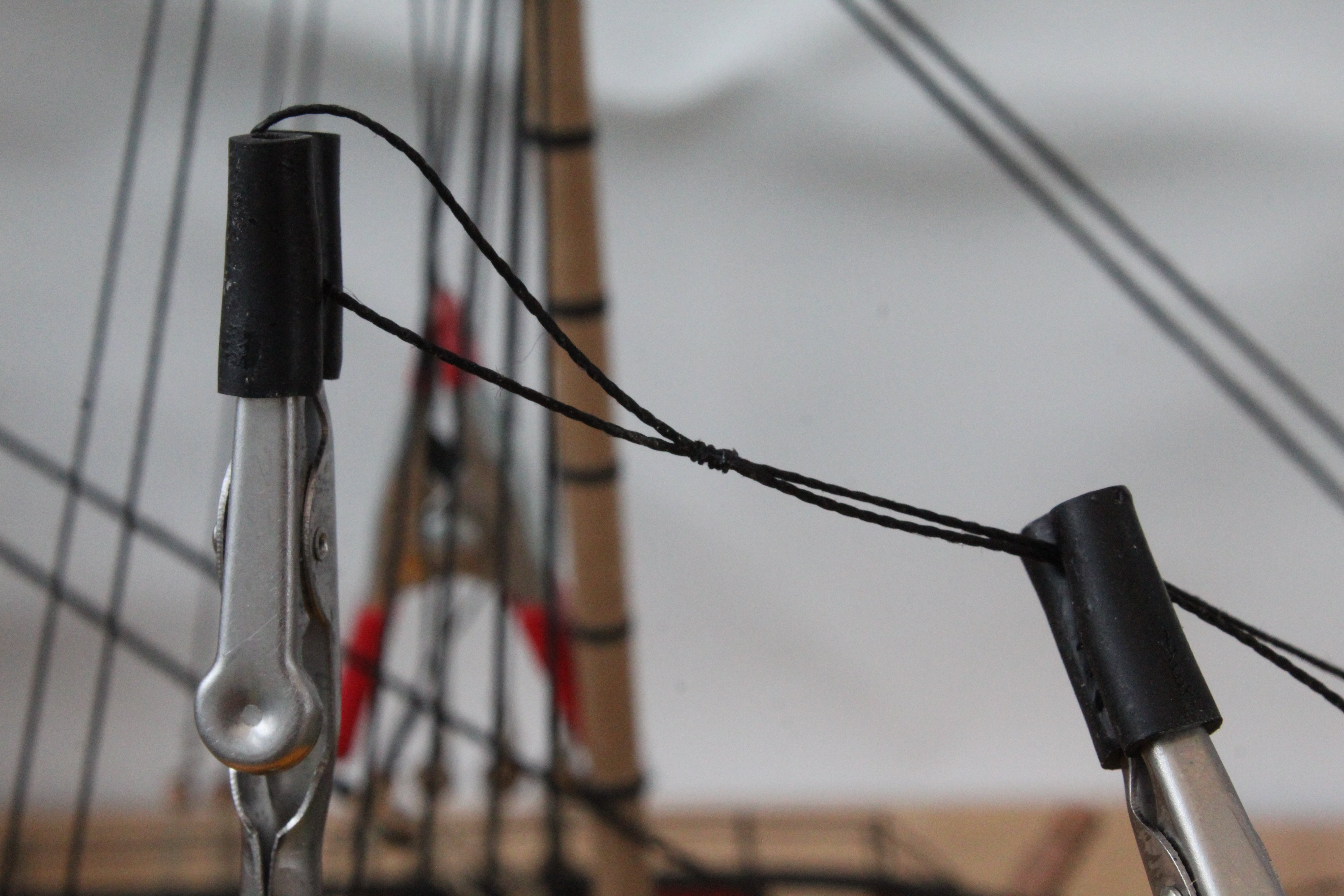
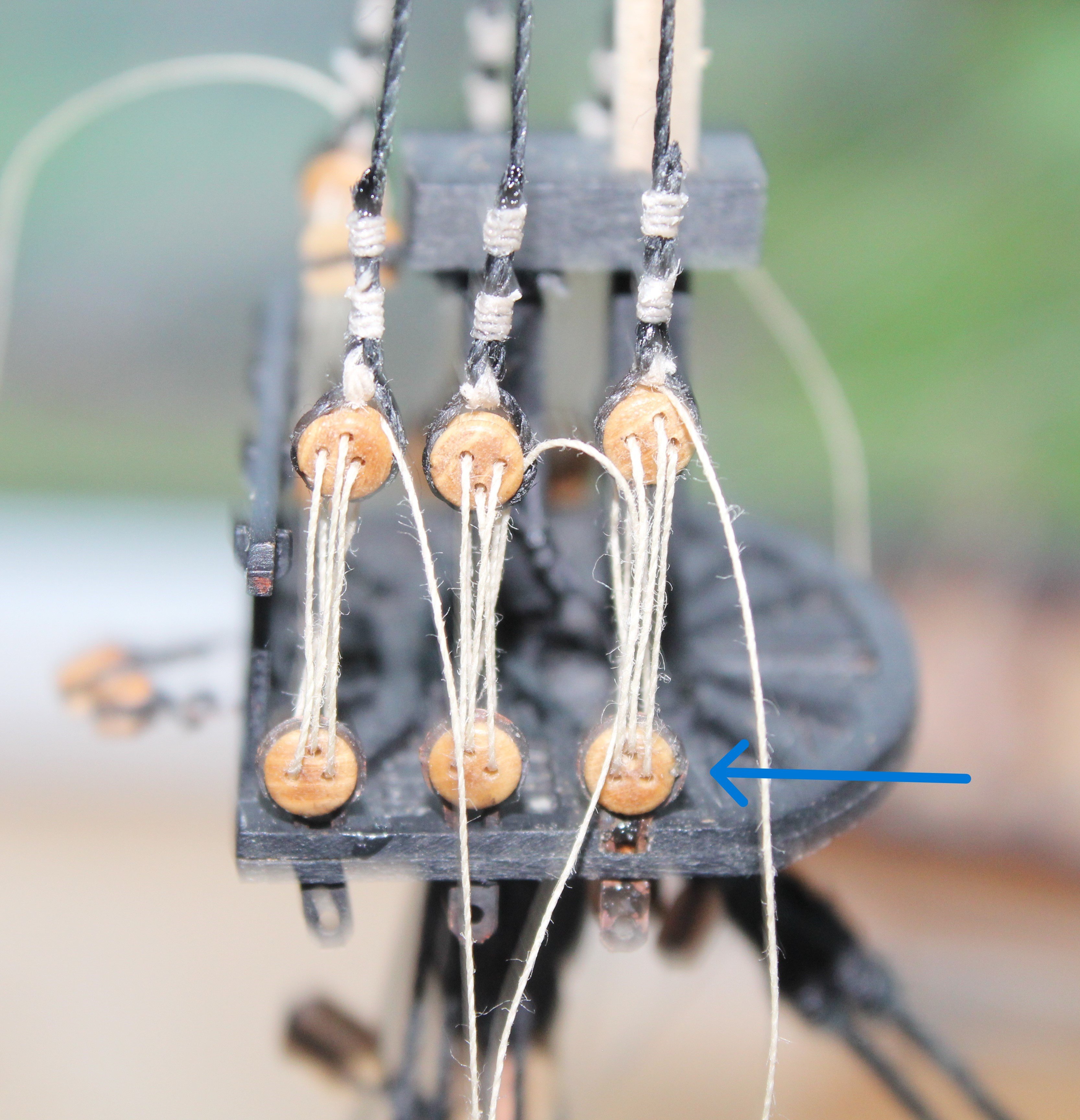
Work has continued with the topsail mast shrouds. Following on from my last post the next stage in the process was to quickly check the shrouds with the lanyards to see if any further adjustments are necessary. I am using clamps to hold the strops in place for the time being.

Happy with how they were looking I went ahead to glue the strops in place and then completed the shroud seizing.
When I did the next test fit typically one of the shrouds did not look very good and I did notice its deadeye was upside down. Pity I did not notice a more fundamental problem. More on that later in this post.

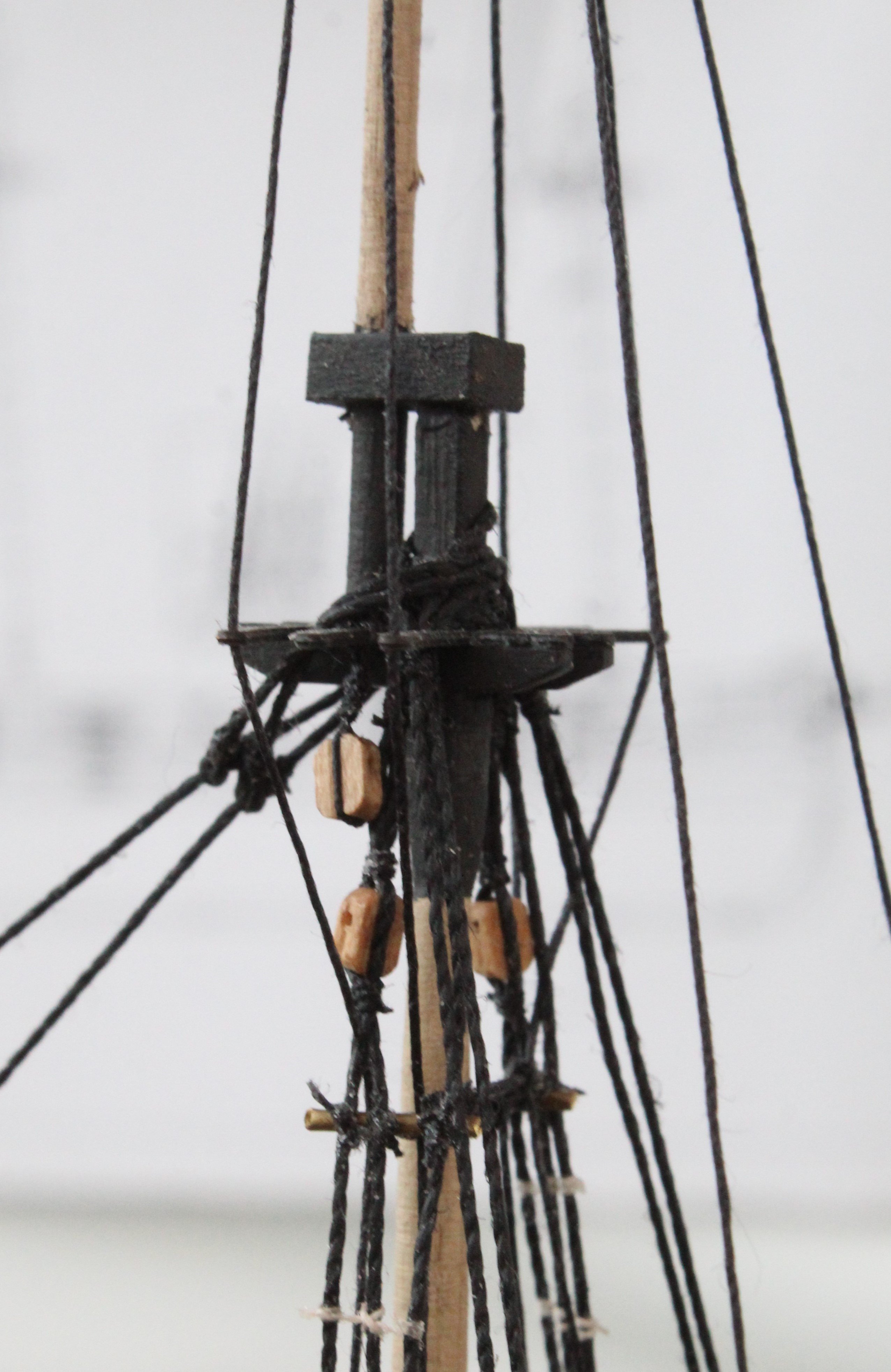
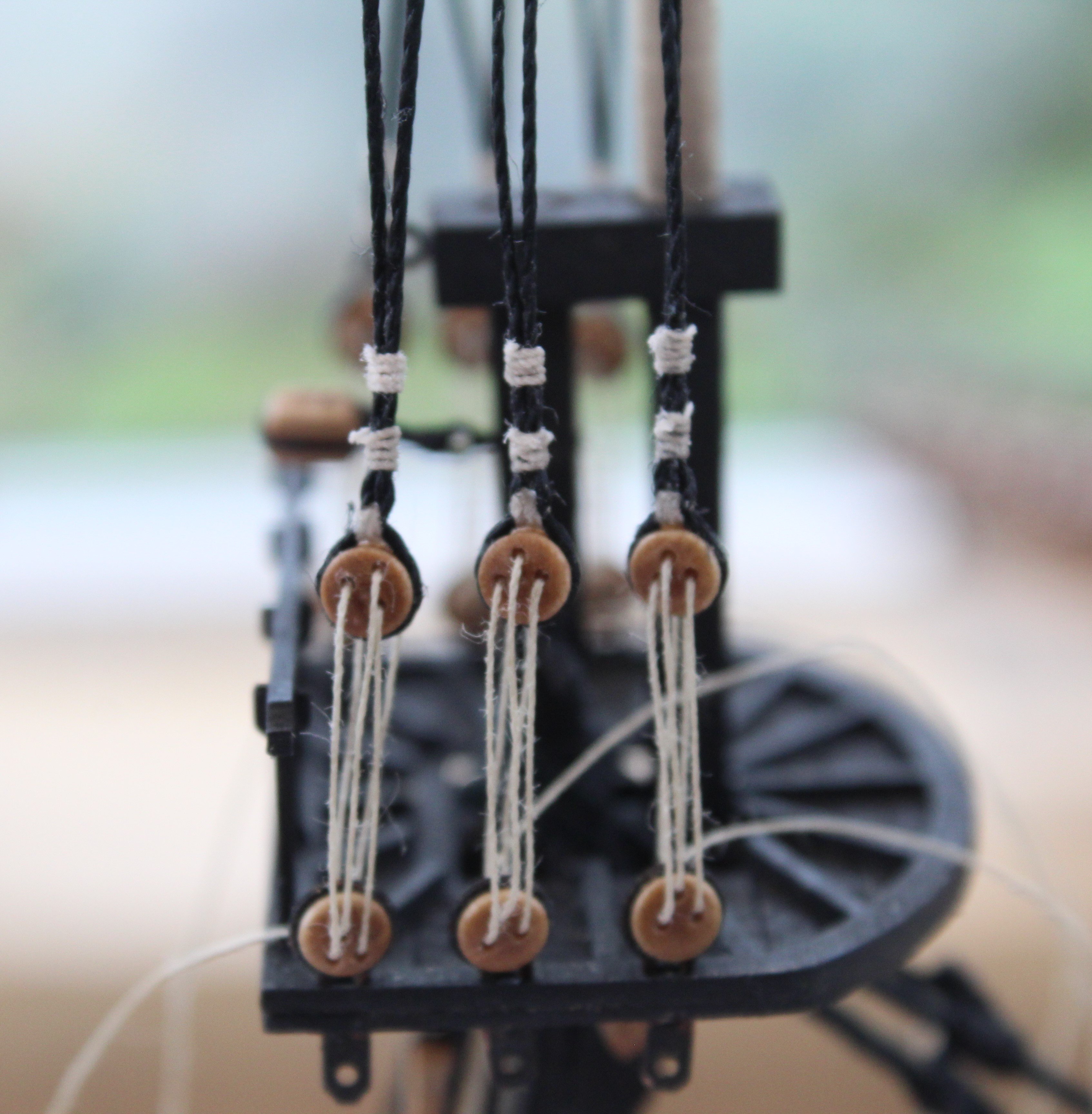
A block has to be fitted between the first and second shrouds which is used for the yard lifts.
It is easier to fit these blocks before the shrouds are fitted. With the block placed between the first two shrouds it is held in position using my quad hands so the seizing could be added.

When I started to complete the rigging I finally noticed that I had made a big school boy error when I added the deadeyes to the strops.

The deadeyes were pretty firm in the strops, and I was unable to rotate some of them when I tried. I then tried to release the strops from the platform, using a bit of acetone to loosen the glue. I ended up damaging the platform edge when I finally released the first strop. Therefore I have decided to live this error for this model, as once built it will not be on display.
-
Date: 06/10/2024
Time worked today: 4 hours.
Total time spent on build: 112 hours.
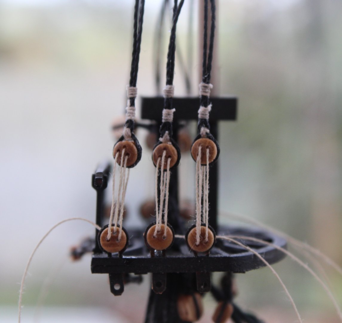
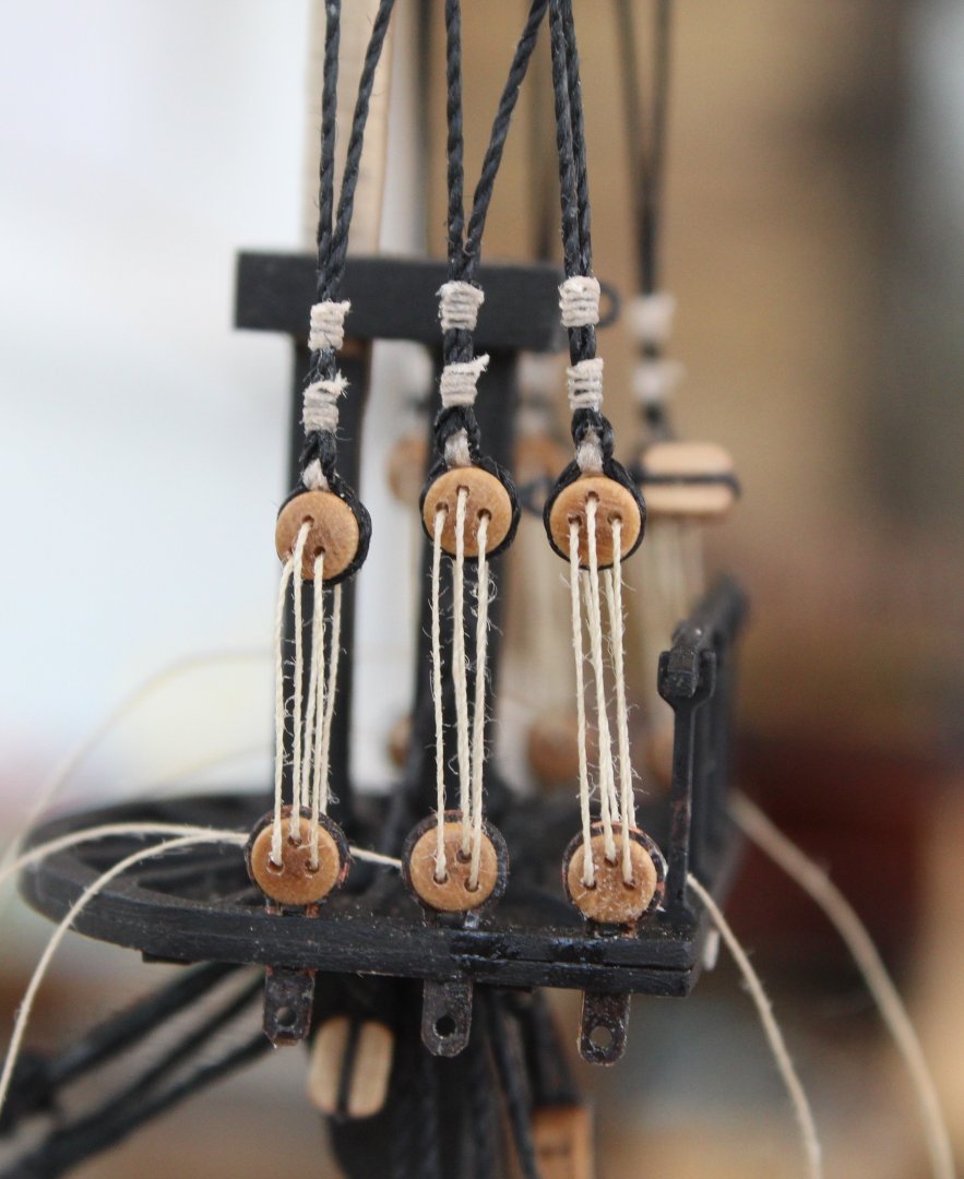
Topsail Mast Shrouds Part 1
As is the norm over recent weeks I seem to be doing plenty of rework. Some is due to silly errors on my part and some due to my completed work could be done much better. This theme has continued with my work on the topsail mast shrouds.
I started the process by cutting the required lengths for all the topsail shrouds and then proceeded to make the loops so they could be added to the topsail mast. So far so good!
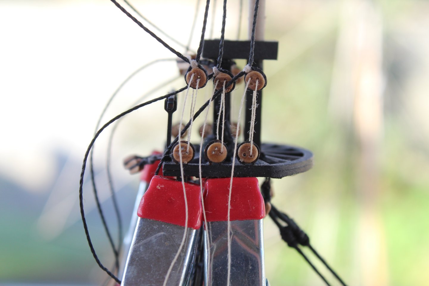
When I did a test fit of the shrouds, I noted two problems. When looking at the next photo the two problems are:
a) The shrouds are sitting on top of each other, and it is not possible to position them side by side. The reason for this problem is the seizing thread used was to thick
b) The seizing also needs to be positioned to just below the crosstrees as there not enough room between the crosstrees otherwise.
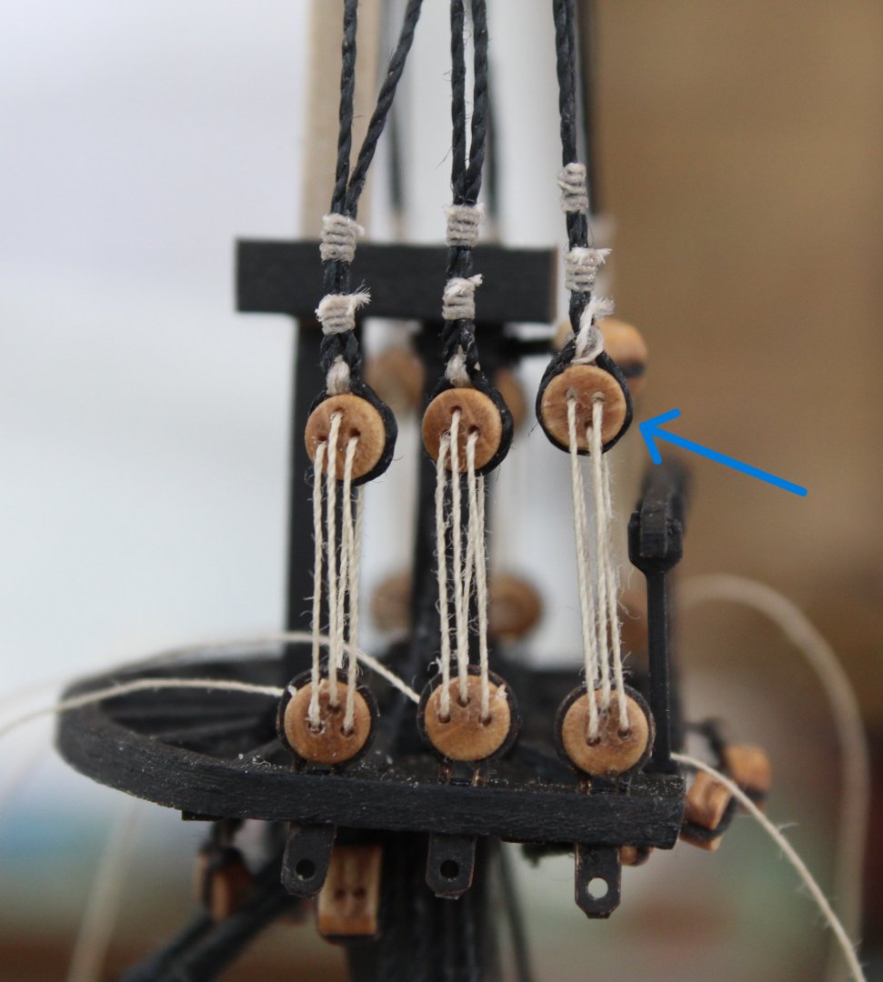
The seizing was redone using thinner 0.1mm black thread and looks much better.
With the seizing was positioned below the crosstrees it looks much better on the Indy.
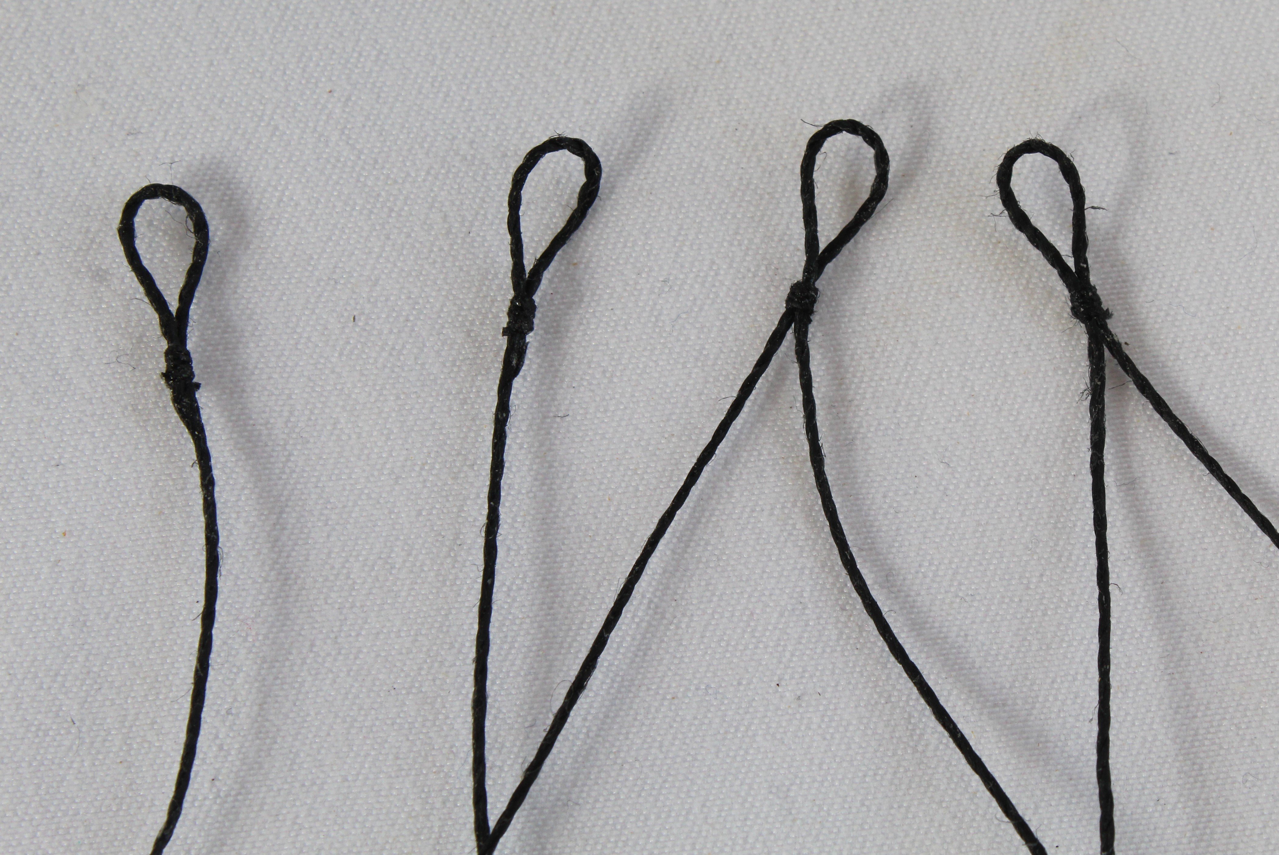
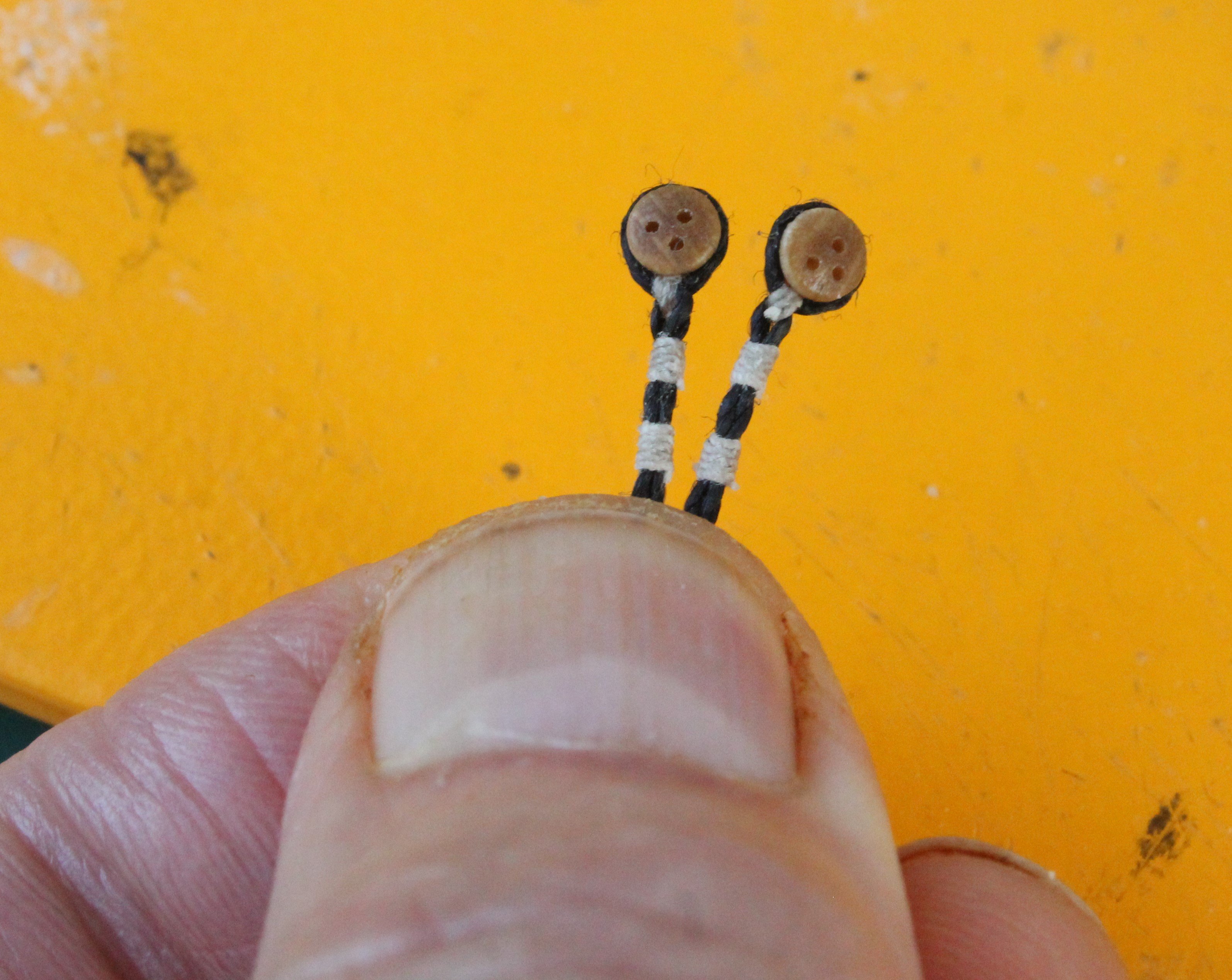
When adding the deadeyes to the shrouds I have opted to try a new method, which is detailed below.
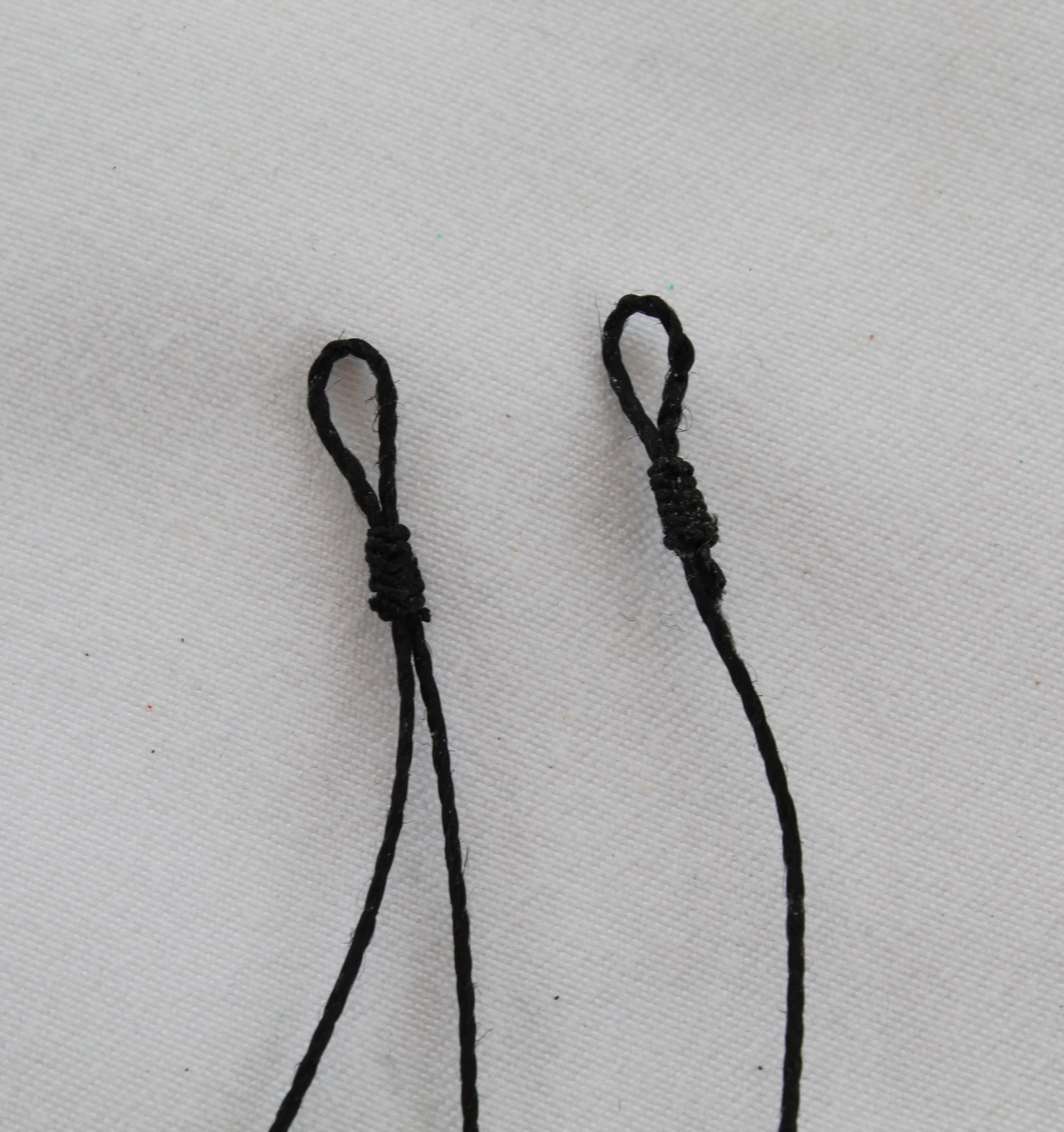
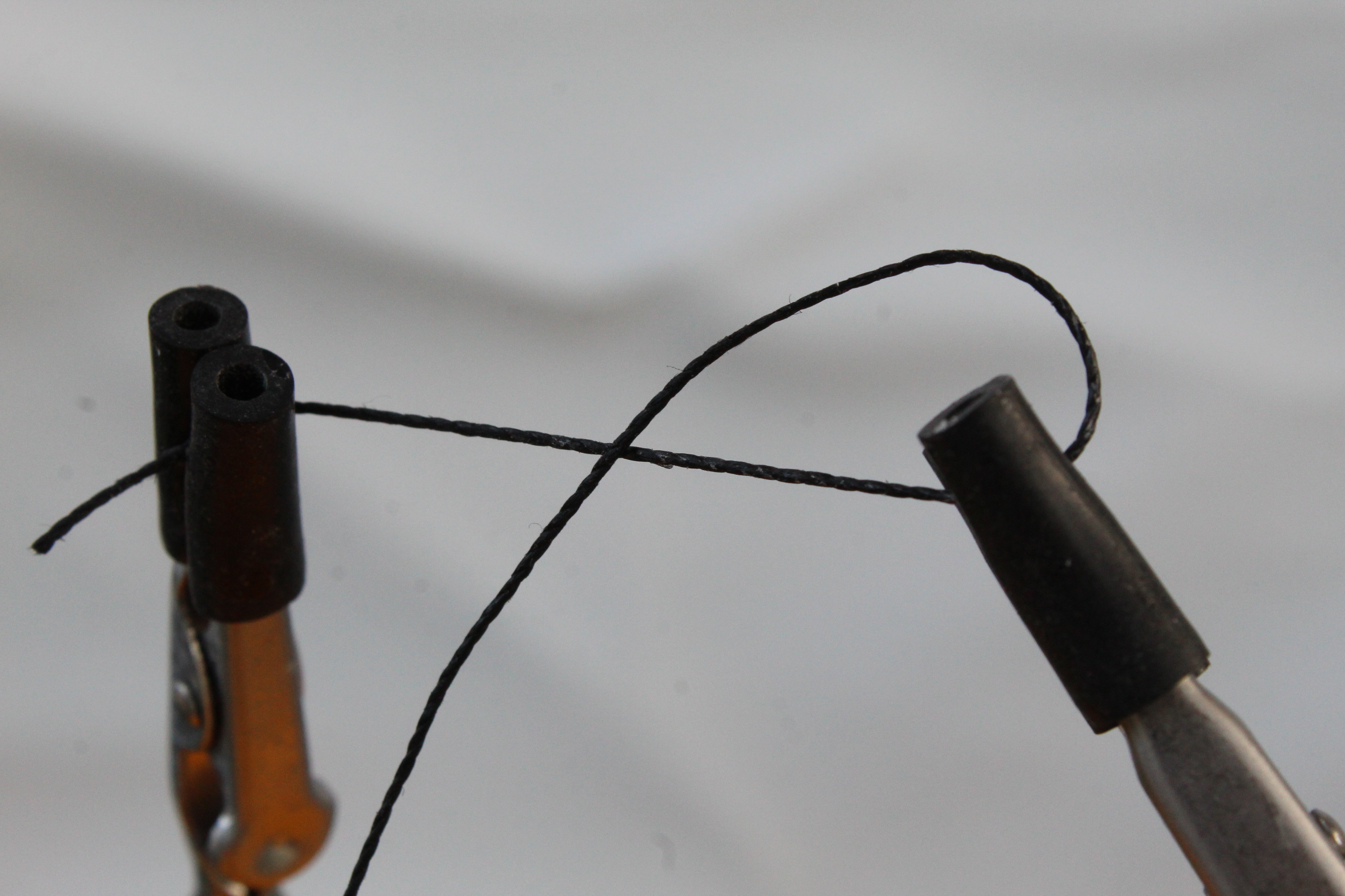
Step 1 – Make a loop and position in the quad hands.
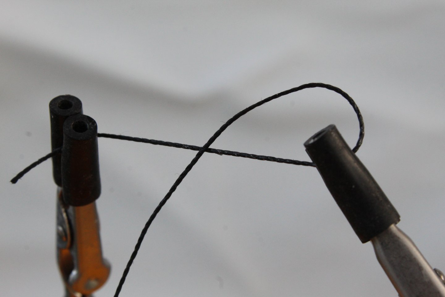
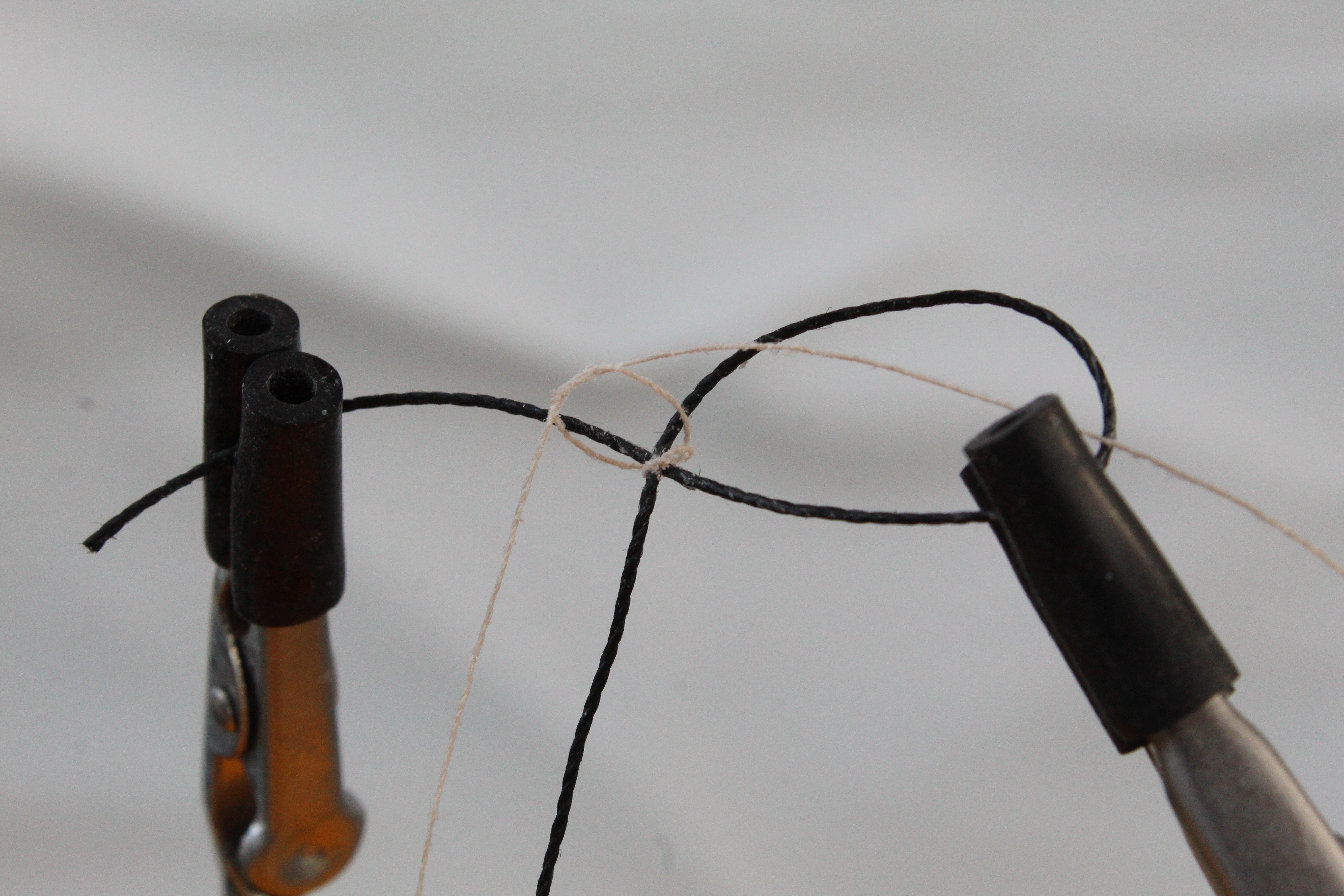
Step 2 – Use a simple crossover knot start to the seizing
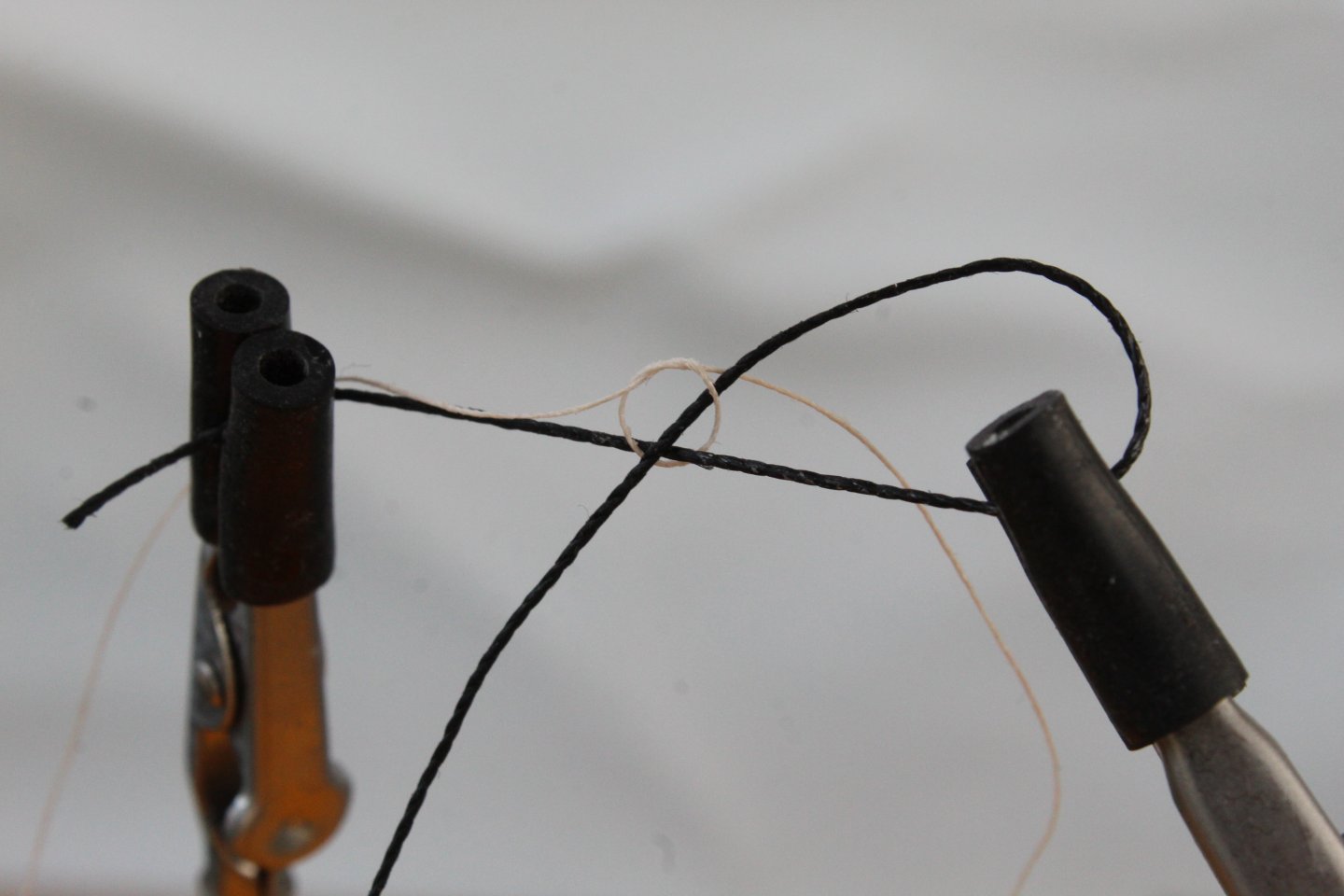
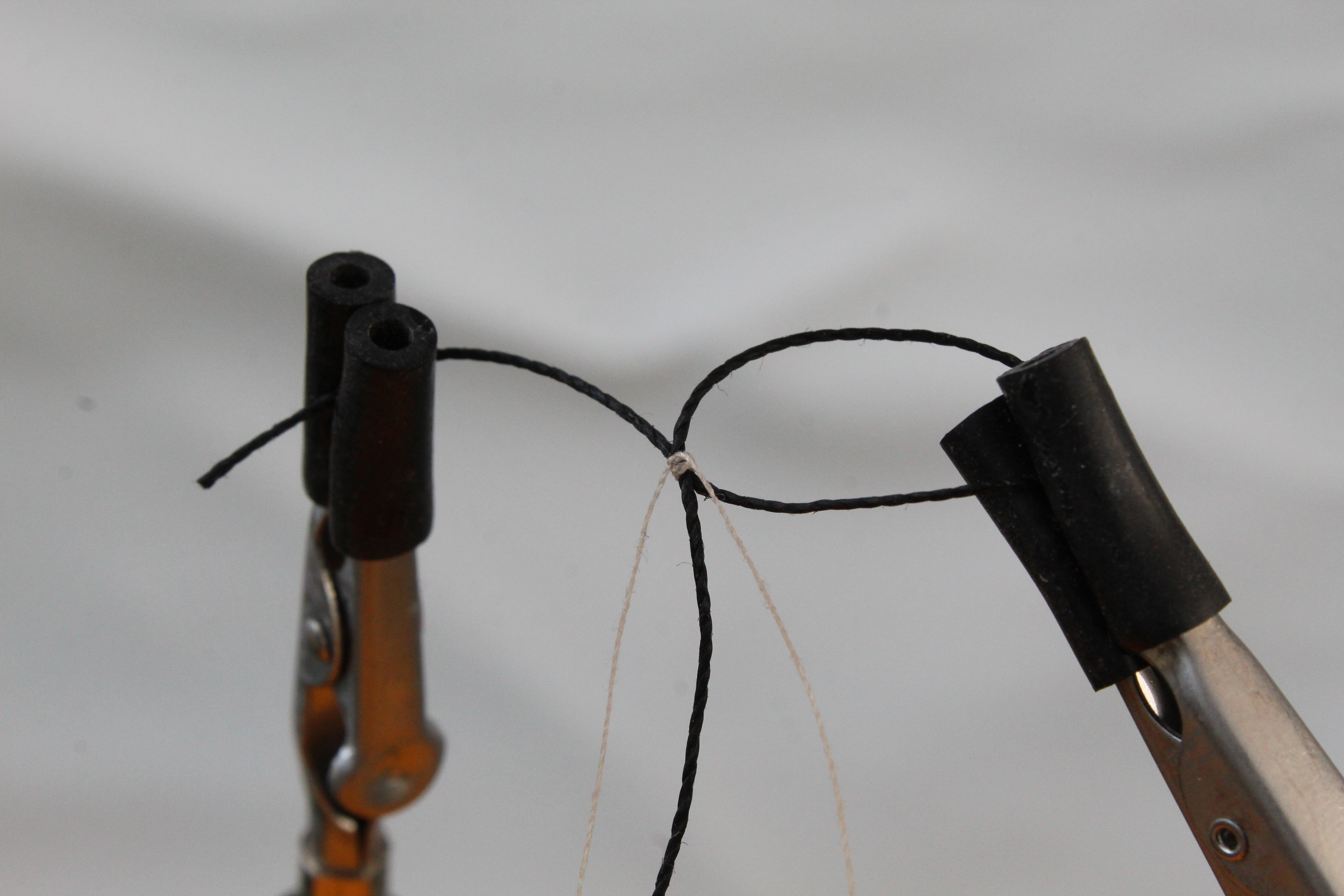
Step 3 – Loop the seizing thread around and make a second crossover knot

Step 4 – Repeat step 3 once again.
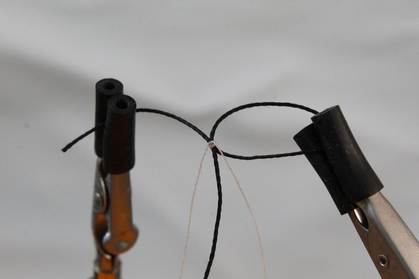
Step 5 – Adjust the position of the loop to the required position.
Step 6 – Close the loop around the deadeye and adjust the position as necessary.
Step 7 – Check position of the deadeyes are level using the quad hands.
Step 8 – After a test fit on the Adder to check the deadeyes are in the right position and look level with each other add the additional seizing. Note: I did test fit the lanyards to check the deadeye positions were OK.

I will add more photos when I am ready to add the lanyards.
-
-
-
Date: 02/10/2024
Time worked today: 6 hour.
Total time spent on build: 108 hours.
Main Mast Stays, Topsail Masts and Jibboom Guys
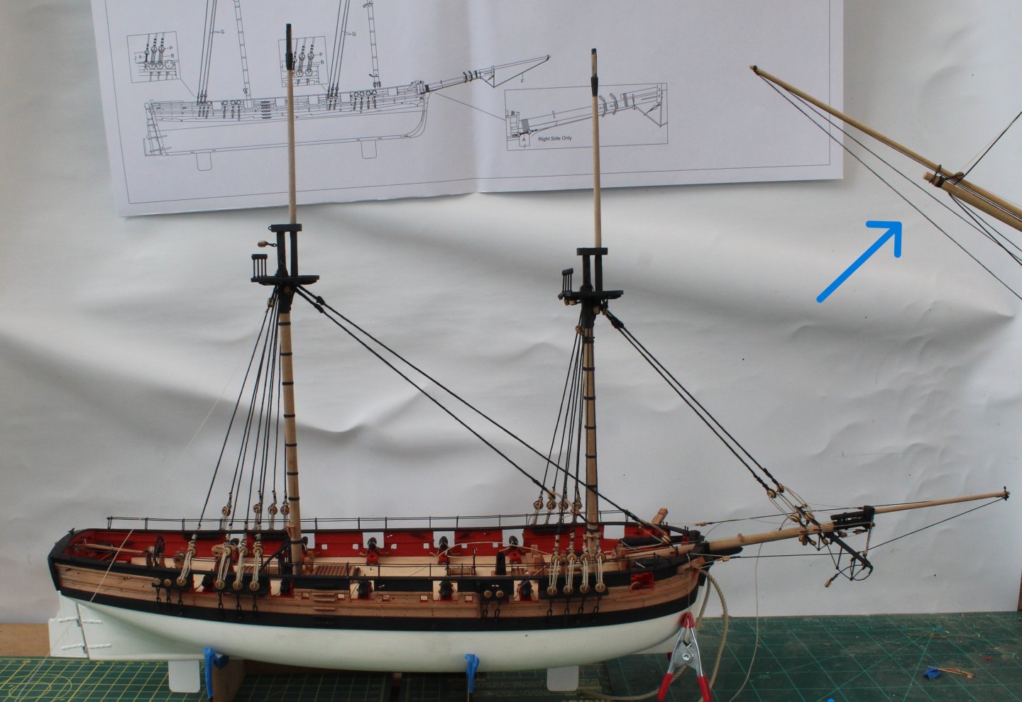
It has been an eventful two days. I thought I had completed adding the main mast stay and preventor stay and took a photo to show the progress.
The next two photos shows the deadeye lanyard rigging for the main stay and main preventor stay.

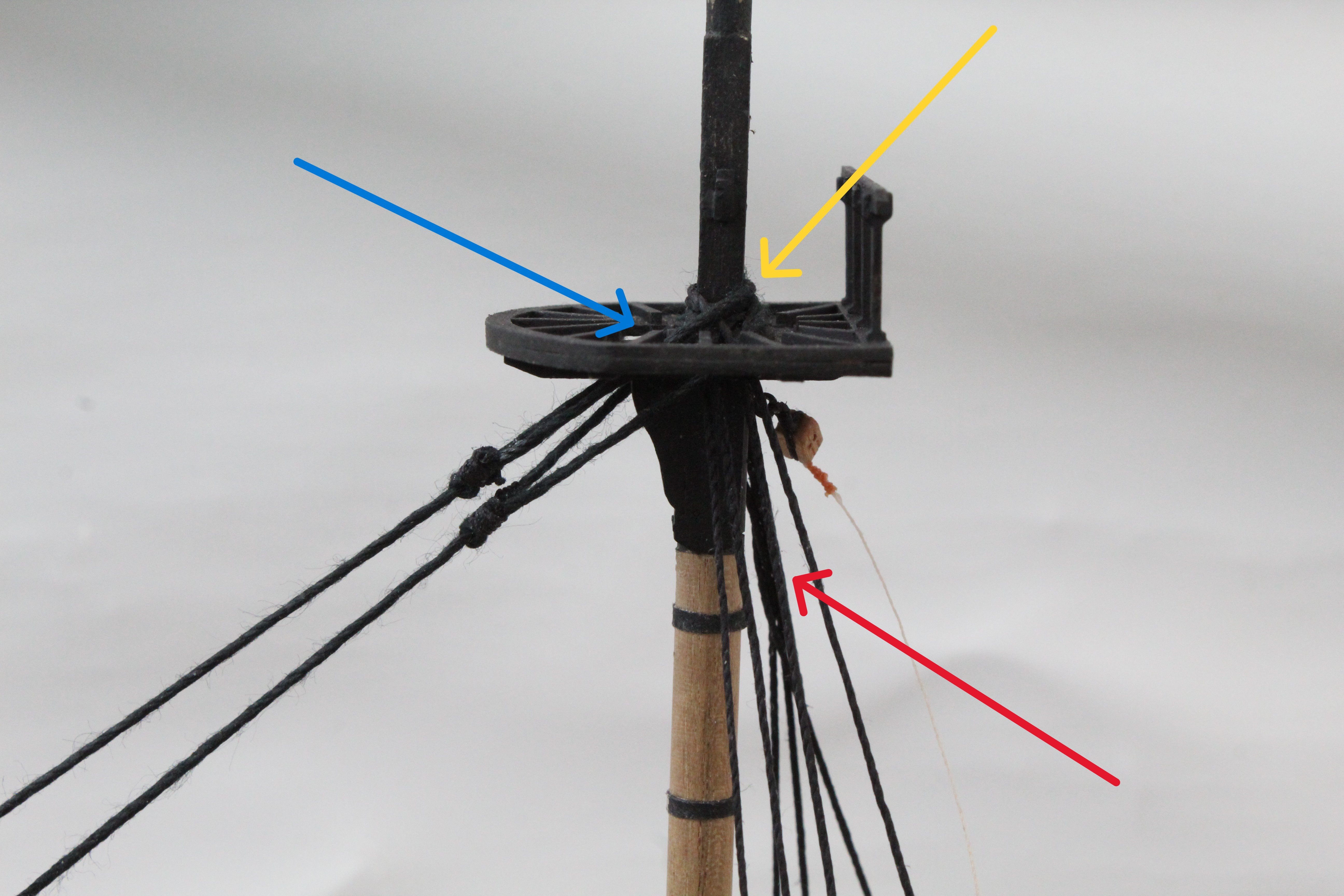
On closer examination I noted that I had made a couple of errors. The preventor stay should wrap around the top of the main mast, as indicated by the yellow arrow in the next photo. If you look closely, as indicated by the blue arrow, you will see I failed to do this. The red arrow shows that one of the main mast shroud lines is twisted.

It took me around 30 minutes to redo the preventor stay and twisted shroud line. Now that I was happy with my work the main and fore topsail masts were added.
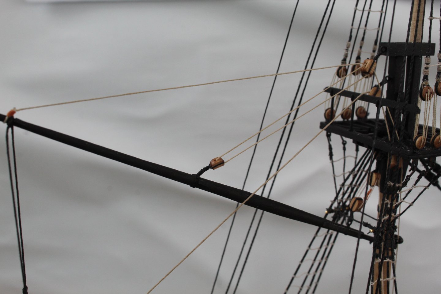
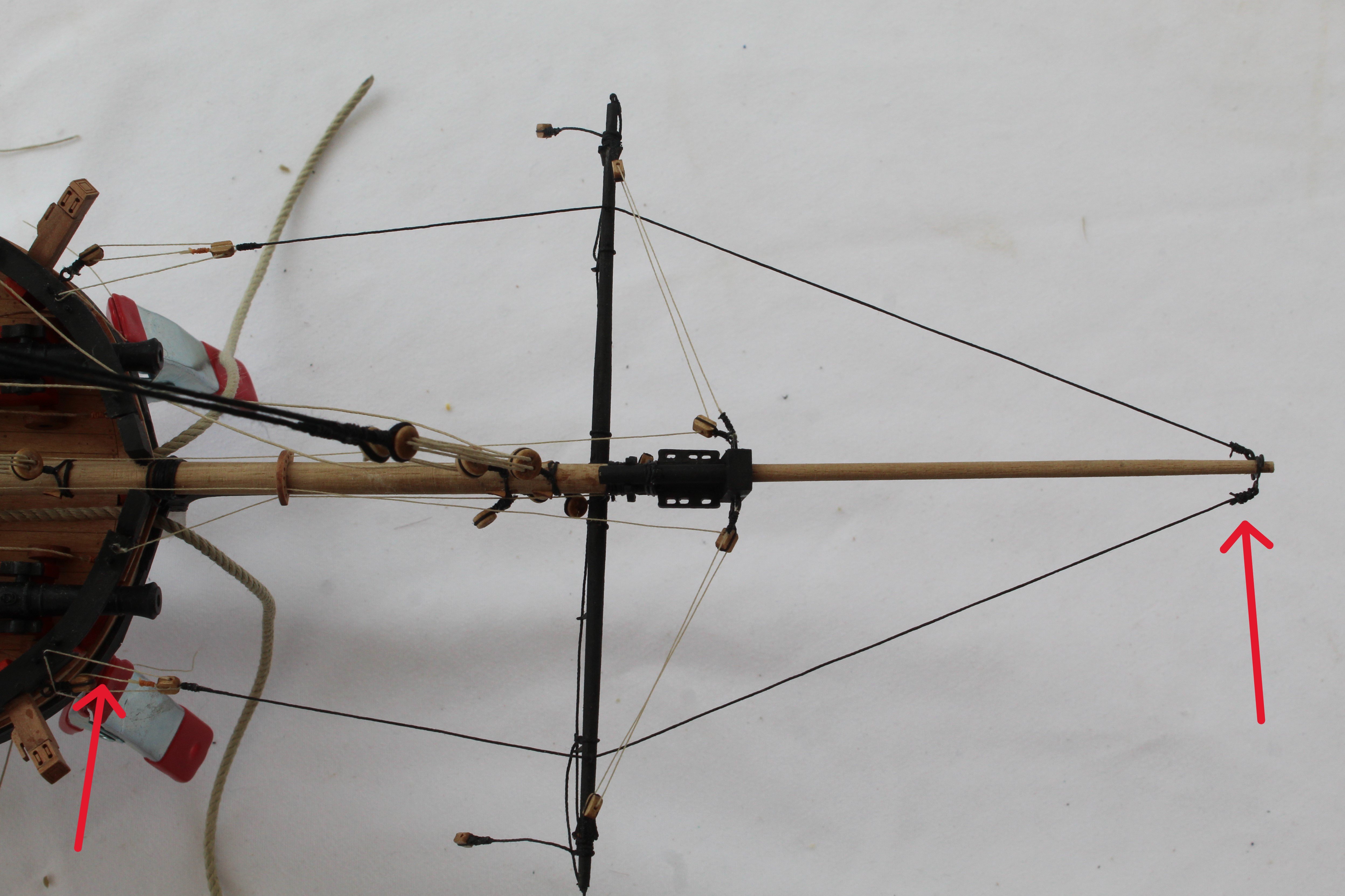
I decided to add the jibboom guy. This should have been a fairly straight forward task. The two guys (left and right sides) are secured to the end of the jibboom and then pass through eyelets located on top of the spritsail yard and are then secured to the hull via a double block arrangement. On completion of this task I took a photo and noted two errors which I have highlighted with arrows in the next photo.
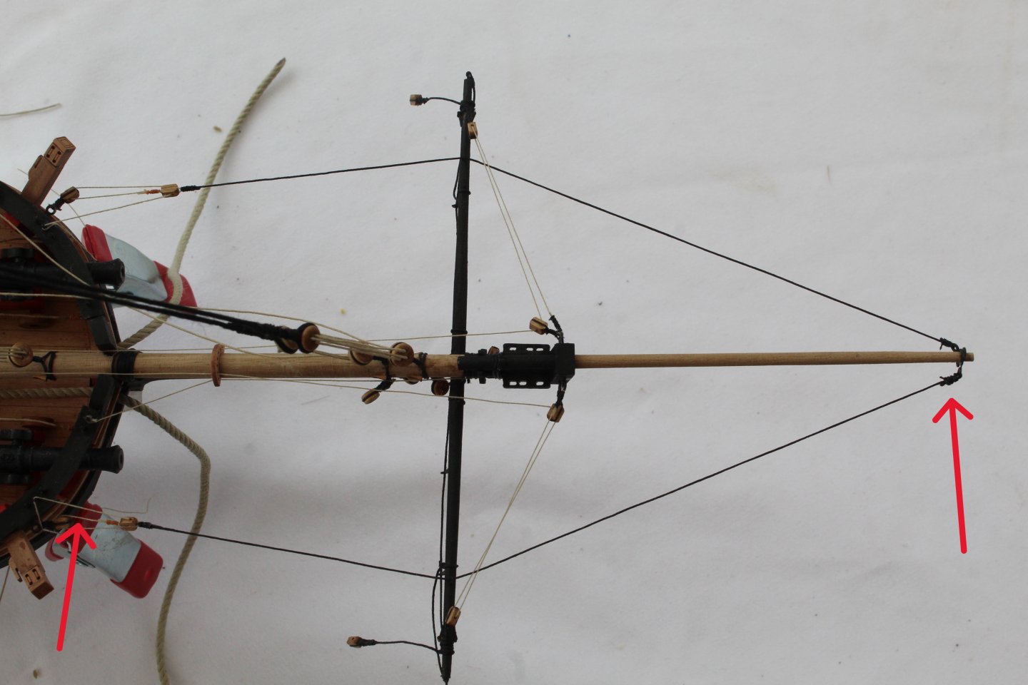
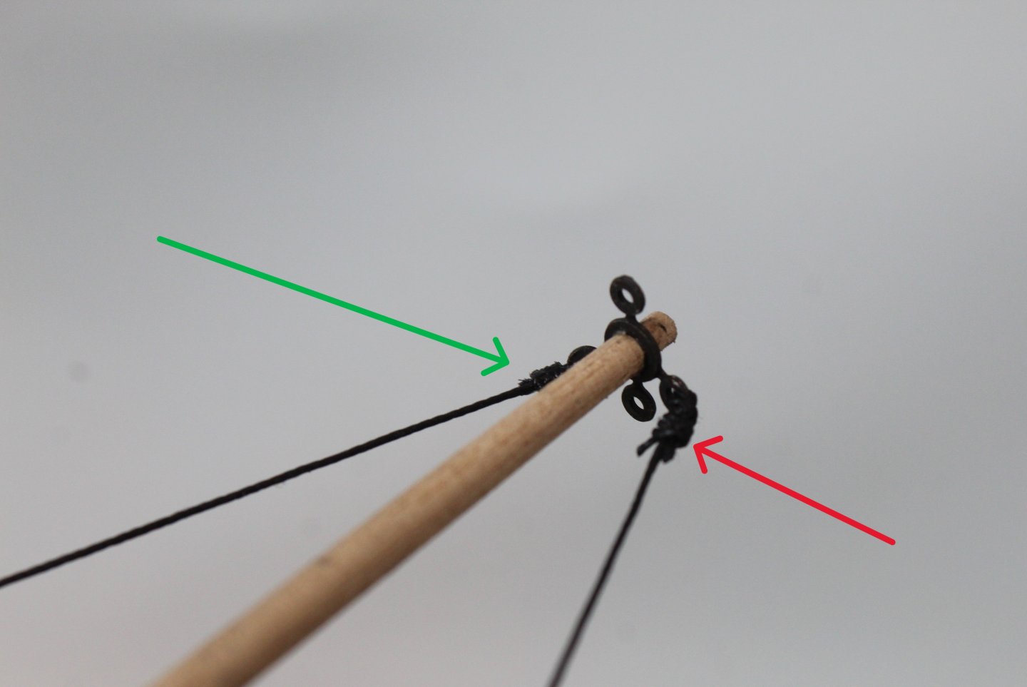
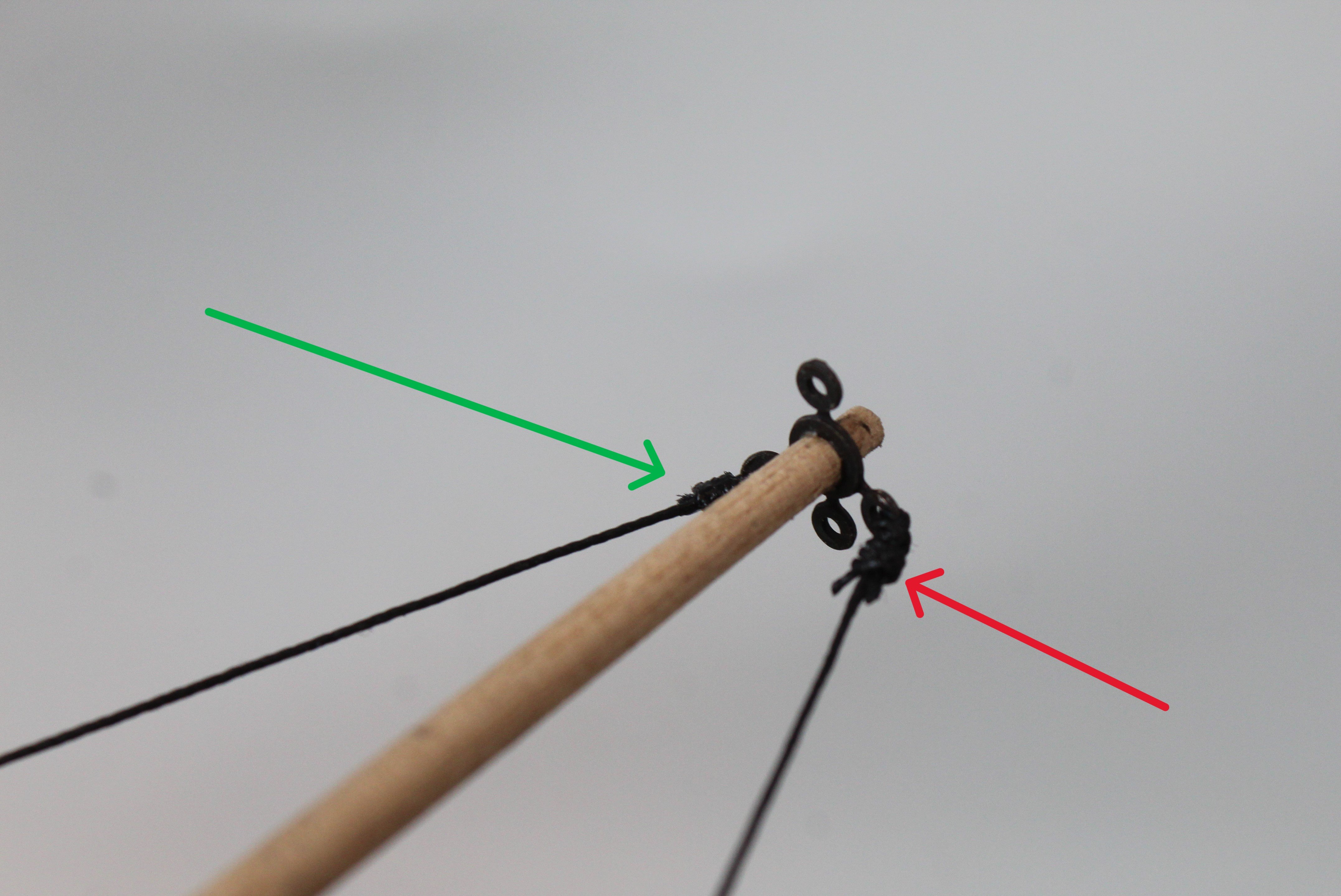
The most obvious error is I used the wrong seizing thread when securing the right-hand side guy to the end of the jibboom. You can see the difference in the next photo, green is OK, red is not OK.
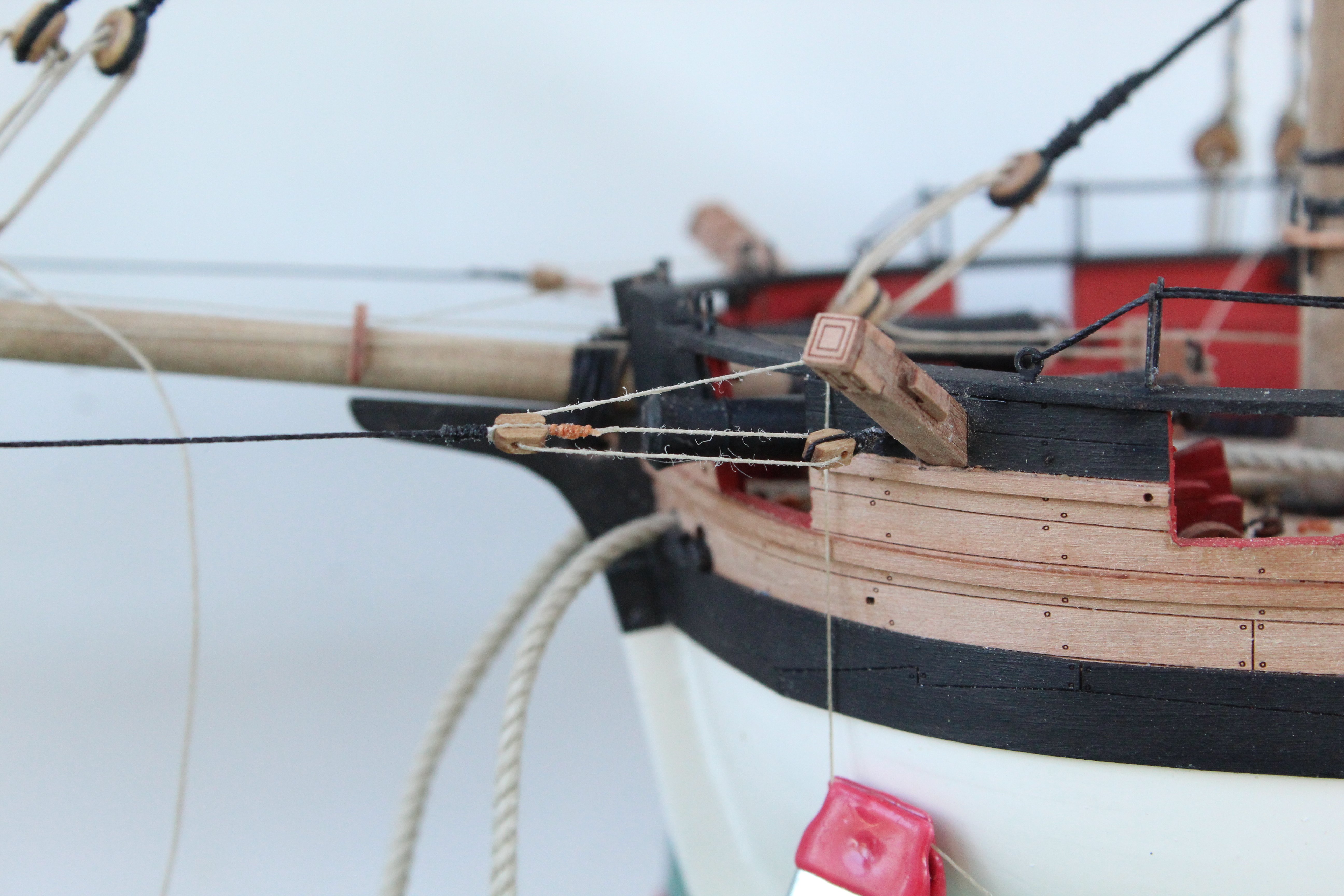
The double block arrangement is not symmetrical. The left-hand side is the better arrangement in my opinion.

The right-hand side needs to be redone as the gap between the two block is to close in my opinion and compared with the left-hand side.

- ECK, KARAVOKIRIS, chris watton and 9 others
-
12


HM Gun Brig Adder 1797 by Glenn-UK - Vanguard Models - 1:64
in - Kit build logs for subjects built from 1751 - 1800
Posted
Hello Paul
I had not considered tubing which is an excellent suggestion. I could make a sleeve which may look a bit odd. Food for thought.
THANKS