

alross2
-
Posts
402 -
Joined
-
Last visited
Content Type
Profiles
Forums
Gallery
Events
Posts posted by alross2
-
-
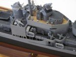
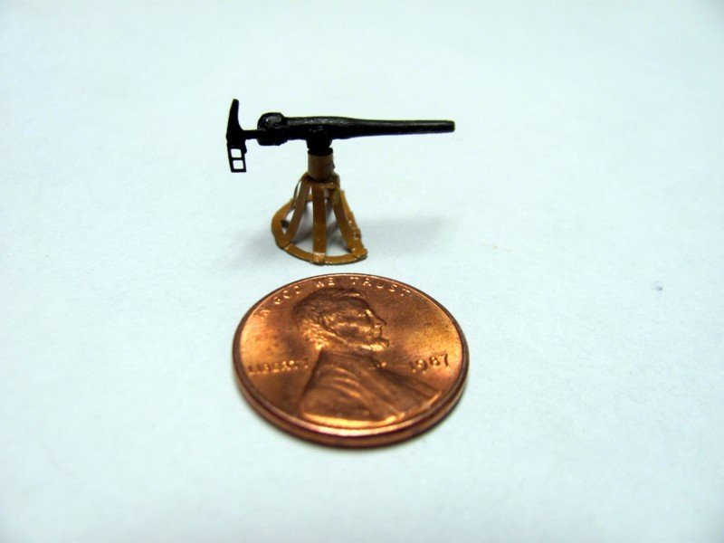
While I'm waiting for some new rigging line for WYOMING, I'm back on OREGON. Painted up one of the 1 pdr guns.
- mtaylor, John Ruy, GrandpaPhil and 6 others
-
 9
9
-
Never mind. I just read an earlier thread on the subject. Should have done so before asking...
- mtaylor and thibaultron
-
2
-
What is the actual vertical distance between ratlines on a 19th C sailing vessel? I'm thinking maybe about 9".
- thibaultron and mtaylor
-
2
-
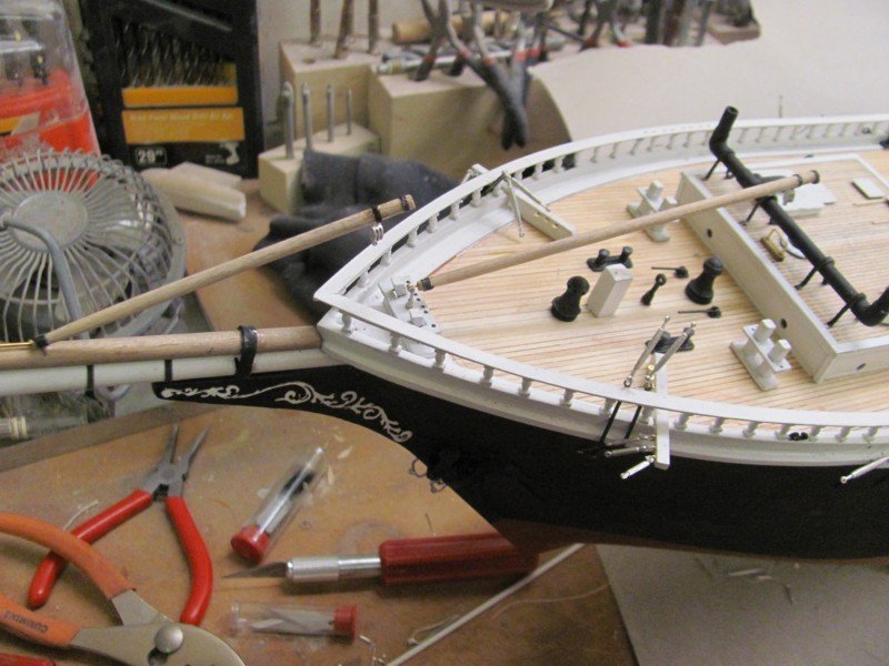
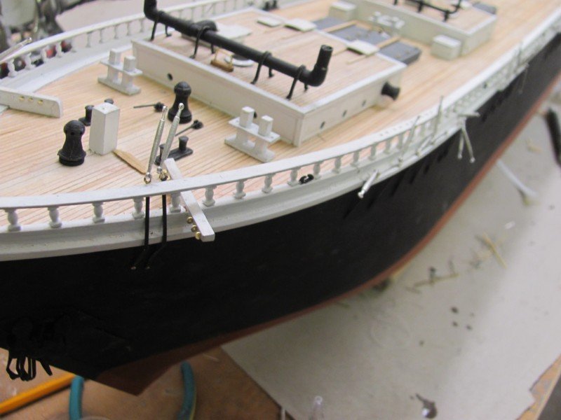
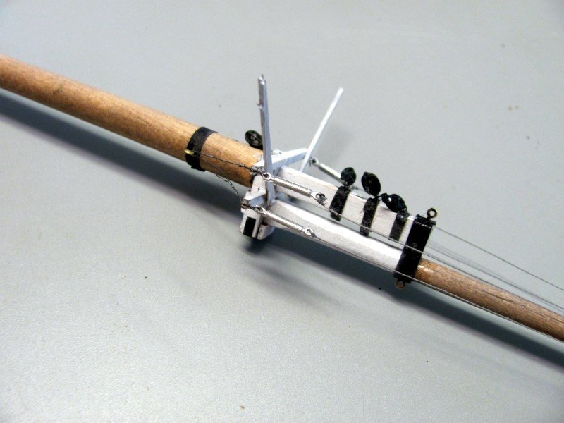
Made and attached the two jib booms this morning.
- GrandpaPhil, Beckmann, John Ruy and 9 others
-
12
-
-
-
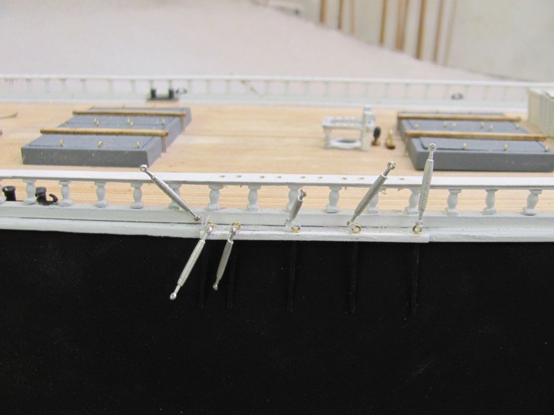
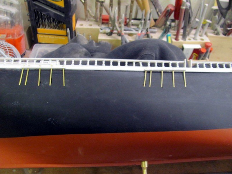
Started attaching the turnbuckles go the chainplates. Only 59 more to go...
- hollowneck, Keith Black, GrandpaPhil and 9 others
-
11
-
 1
1
-
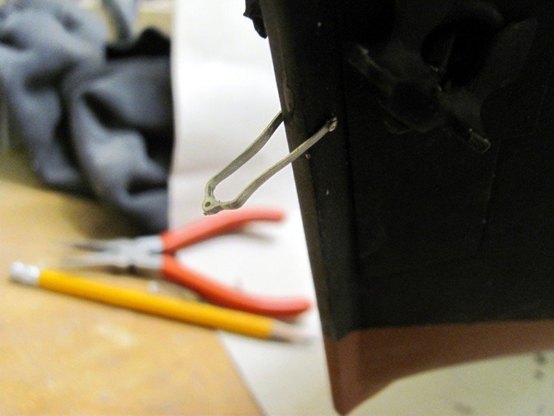
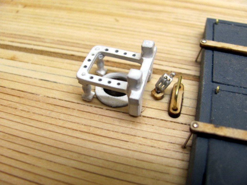
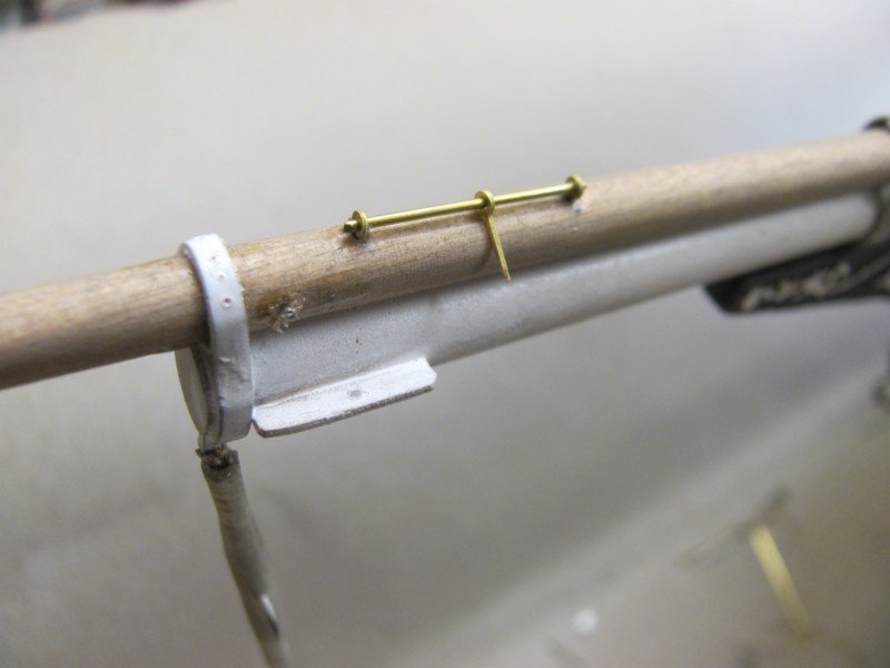
The bobstay irons are going to be a bit fiddly to install. The arms are trimmed to length and a .020" hole drilled at the end of each, then through the stem. A pin is inserted through the three holes, glued to the arms and snipped off. By allowing them to pivot, it makes setting the angle easier when the bobstays are attached. Once they are in place, the irons can be glued in place.
- chris watton, mtaylor, coxswain and 7 others
-
10
-
-
-
There are 120 holes in the cap rail for belaying pins. I decided not to laser them in because of the potential for breakage. So, you have to drill them but there is a template in the kit that will make this less challenging. You align the first two holes with the space between the stanchions, drill the first hole, stick a belaying pin or piece of rod in the hole to maintain alignment, hold the template in place, and drill away. It actually only takes a few minutes and everything is consistent.

-
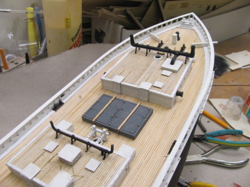
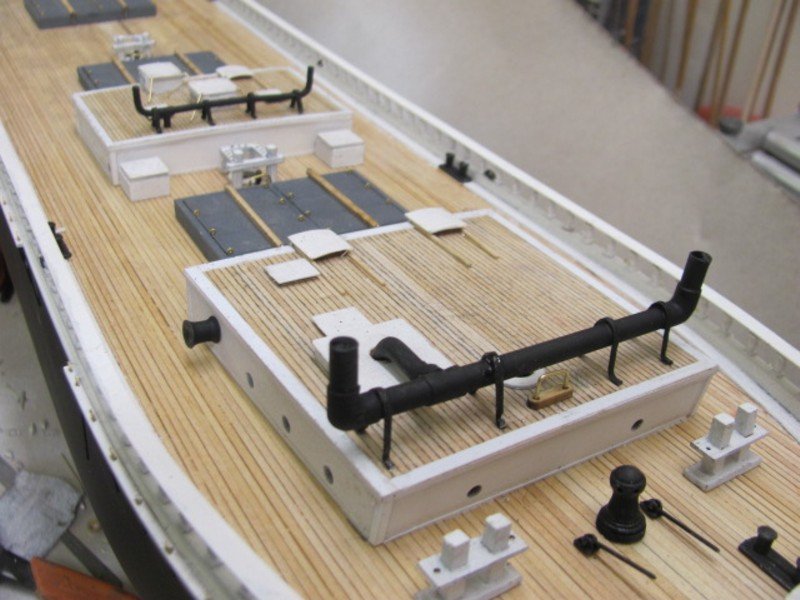
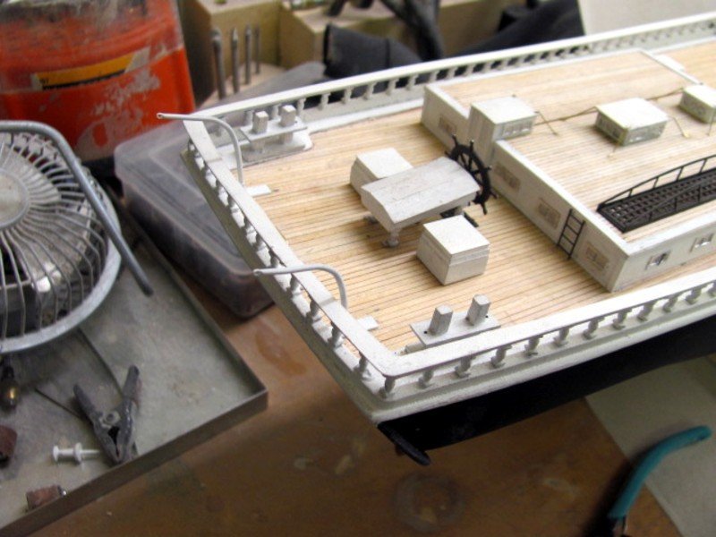
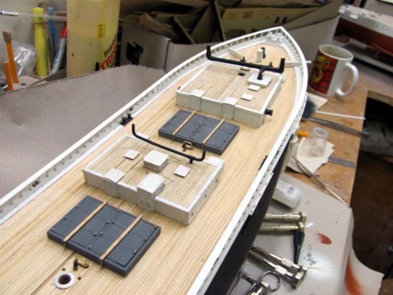
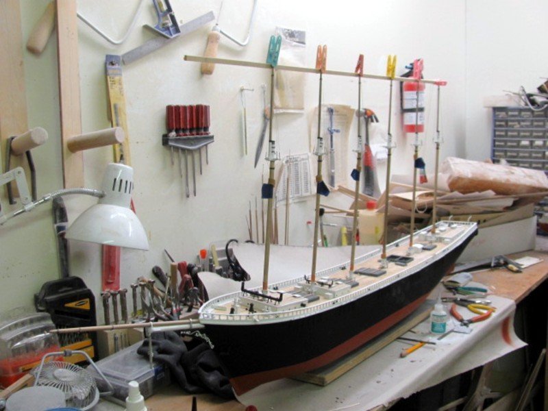
Stacks are now installed on the house roofs. I've also just stepped the #4 mast to serve as an alignment guide for the other five.
- GrandpaPhil, Canute, John Ruy and 8 others
-
11
-
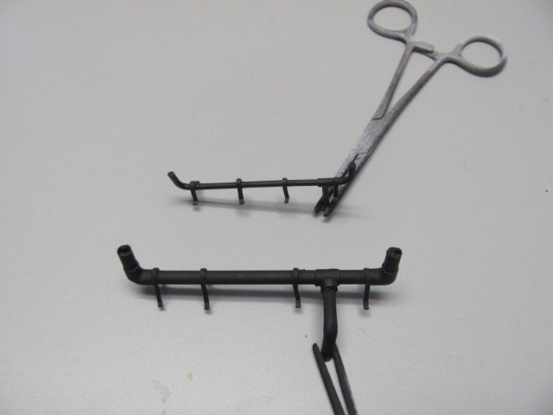
Stack brackets are installed. These are made from 1/64" x 1/16" britannia strips bent over a jig (included with the kit) and trimmed. As an aside, forceps are great for holding items for painting. These are cheap ones that I toss in lacquer thinner after I'm done painting. They clean up easily and can last for years.
- BobG, thibaultron, chris watton and 4 others
-
7
-
Some details of the MAINE and OLYMPIA kits I developed for BlueJacket.
(2018_07_2316_35_27UTC)(2020_01_2301_21_01UTC).thumb.JPG.49bd5d513b1511d5ce58ad875a8e3ffc.JPG)
(2018_07_2316_35_27UTC)(2020_01_2301_21_01UTC).thumb.JPG.b7dde29e4fdffbd3944e65d2851586d0.JPG)
(2018_07_2316_35_27UTC)(2020_01_2301_21_01UTC).thumb.JPG.50c64cb8b17b8f08c12f5f83f6098ddf.JPG)
(2018_07_2316_35_27UTC)(2020_01_2301_21_01UTC).thumb.JPG.db00f163b5cb1a7d07bd8cc95ae62ee6.JPG)
(2018_07_2316_35_27UTC)(2020_01_2301_21_01UTC).thumb.JPG.0ccb3ad369acfcdcd87c01cb50aa6b1c.JPG)
(2018_07_2316_35_27UTC)(2020_01_2301_21_01UTC).thumb.JPG.f25b829310196fedd90c3d3c10f6338b.JPG)
- mtaylor, Canute, GrandpaPhil and 2 others
-
5
-
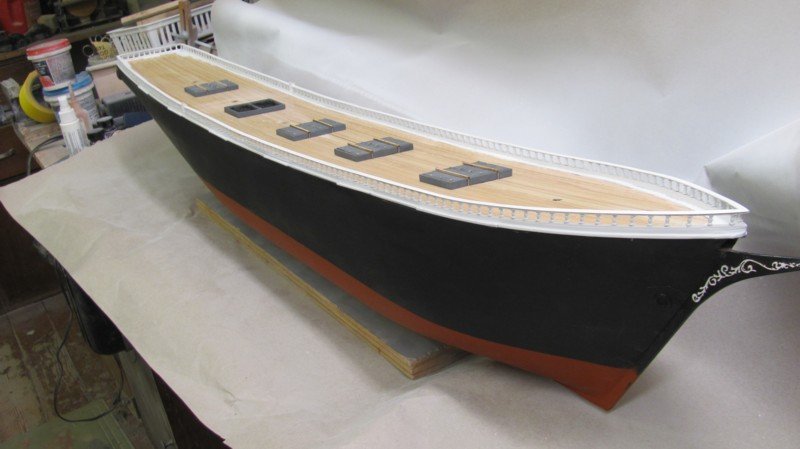
Almost time to start putting in the sticks. Still have to make the brackets for the two stacks, drill holes in the cap rail for belaying pins, and add the rudder.
- chris watton, ccoyle, thibaultron and 10 others
-
13
-
Rather than spend hours looking, I thought I'd start here first. The plans I'm using to develop the kit of WYOMING were drawn by an actual schooner captain who is also a well-known researcher, so I have a warm fuzzy about their accuracy. There is no belaying plan, but that is not much of a problem. I can figure that out based on rigging plans for other schooners. The main problem is that there is no indication of where the halyards on the forecastle mast (that's what P & S called it, as well as #1) tie off. The plans do not show a fife rail nor a spider band on this forward-most mast. Like many schooners, this mast passes through the fore house and the boom jaw rest is quite close to the roof. WYOMING was flush-decked and did not have bulwarks, only a rail with stanchions which doesn't sound strong enough to support pin rails. There are no indications of pin rails anywhere forward. There are two large wooden bitts just forward of the house, each having two belaying pins, but this doesn't seem like enough to be the belaying points for this mast. So, does anyone have an illustraton of this particular configuration that would clear things up for me?

- mtaylor, allanyed, hollowneck and 1 other
-
4
-
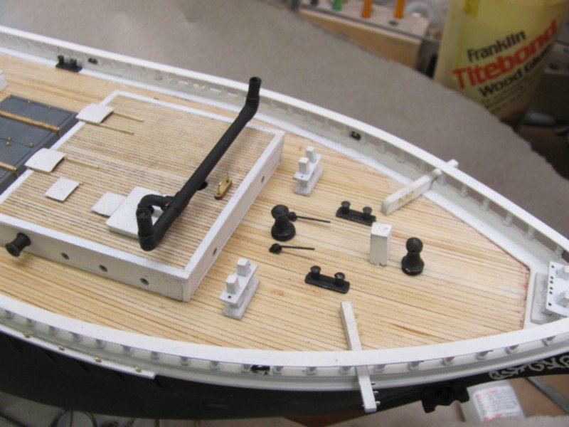
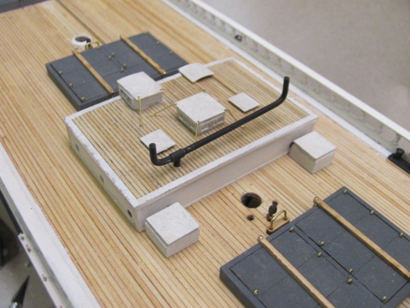
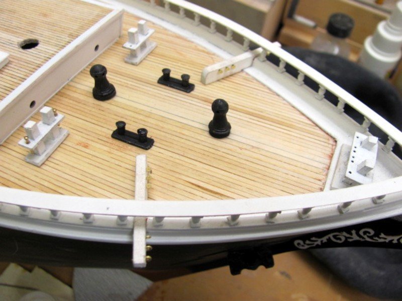
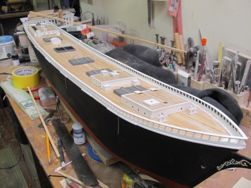
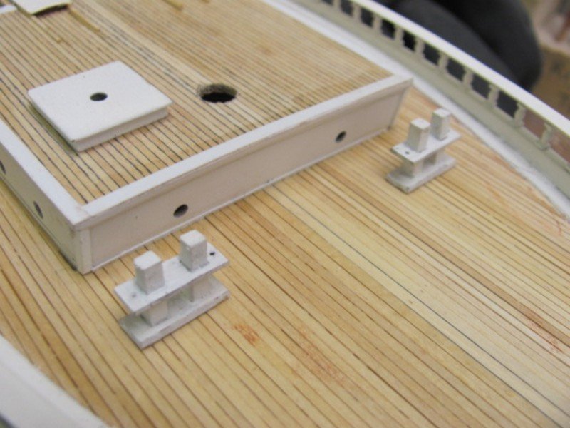
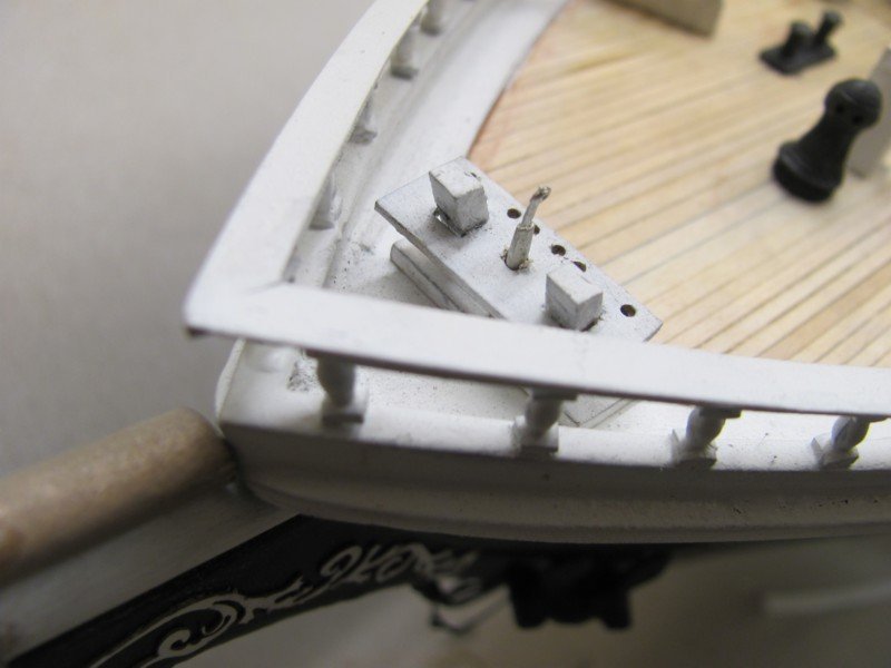
Catheads, horses, and deck pads are on.
- Keith Black, Canute, thibaultron and 6 others
-
9
-
All of the starboard chain plates are now in place. They will be black eventually, as the hull will get another coat of black.
- GrandpaPhil, hollowneck, ccoyle and 7 others
-
10
-
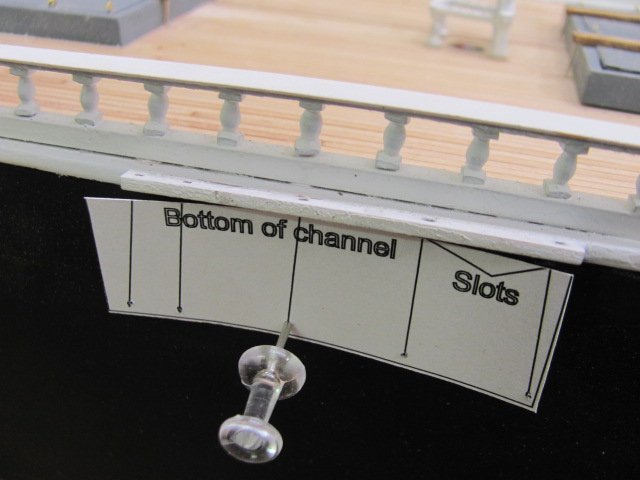
Made two new templates for setting the chain plate angles. One is for the forecastle mast, the other for the other five masts. The top of the template corresponds with the slots in the channel while the bottom corresponds with the bottom of the chain plate, You just align the top section with the channel slots and use a pin or ,020" drill through the bottom holes to mark the position of the lower part of the chain plate.
- thibaultron, hollowneck, ccoyle and 6 others
-
9
-
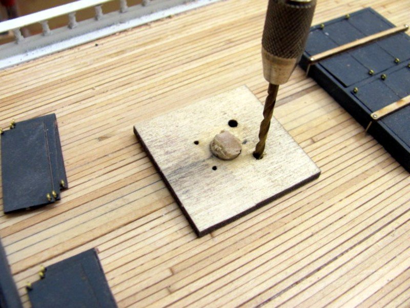
Made up a jig for drilling locating holes for the pegs on the fife rails. There's not much clearance between the mast and inside of the fife rails, so this will align everything properly. It will be part of the kit.
- GrandpaPhil, mtaylor, ccoyle and 7 others
-
10
-
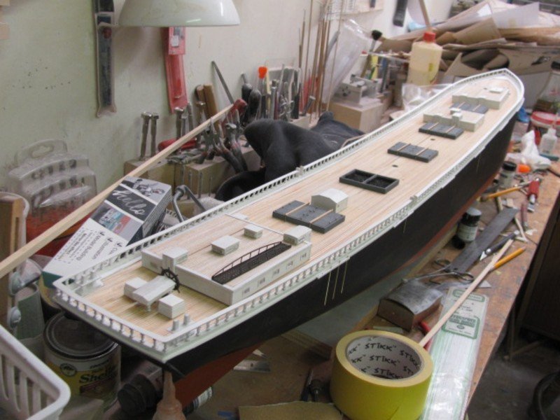
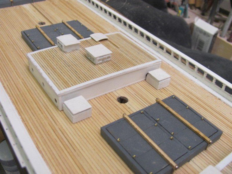
The fore and midships houses are mostly complete and glued down, Got a few more pieces for the aft house, then it will be fixed down. After that, I have to make the deflection rails for the skylights and add the mopboards around the houses.
- thibaultron, Keith Black, Canute and 9 others
-
12
-
Nic will be bringing the WYOMING in its current state to the New London show this week.
- Canute, John Ruy, Keith Black and 3 others
-
6
-
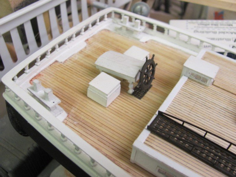
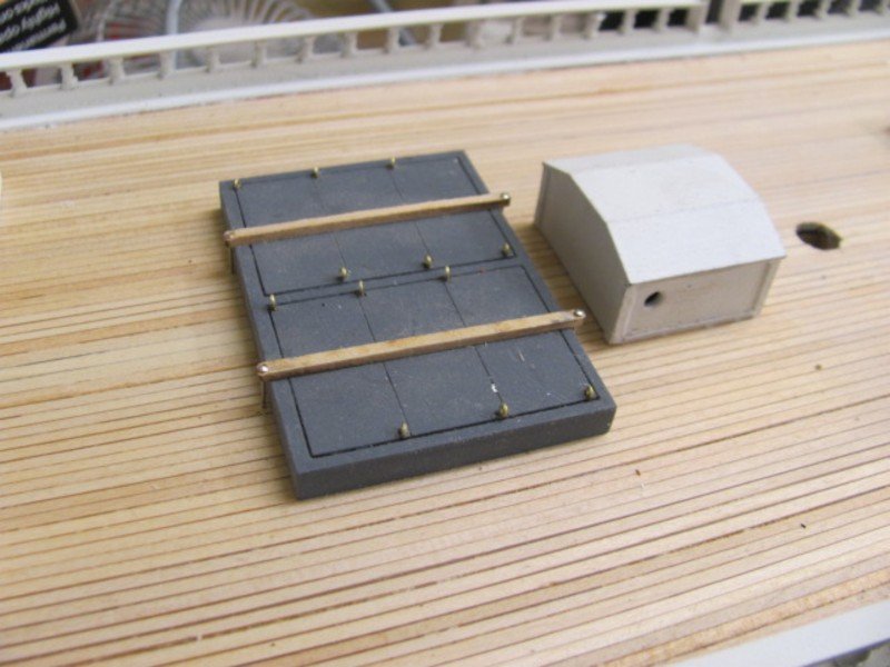
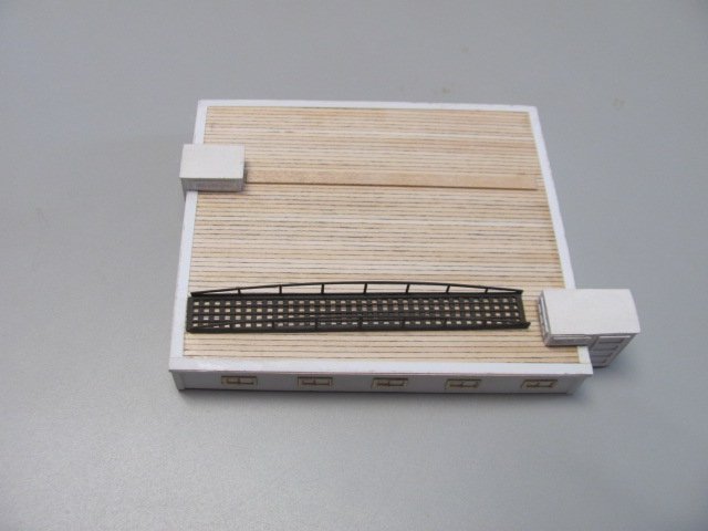
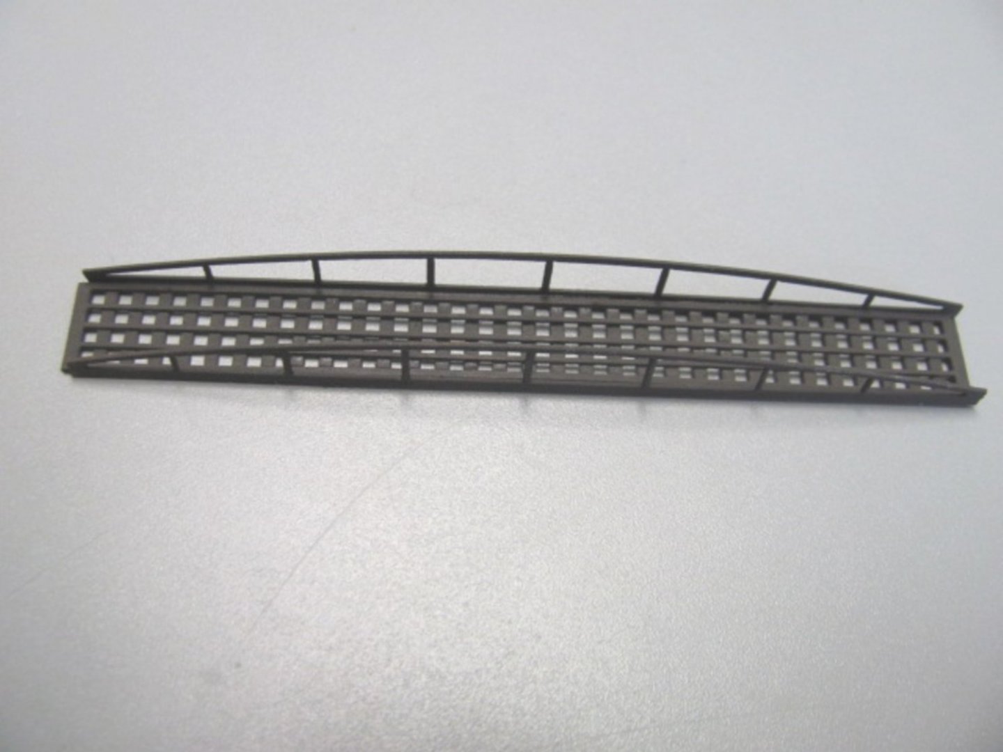
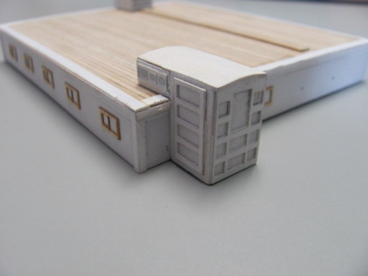
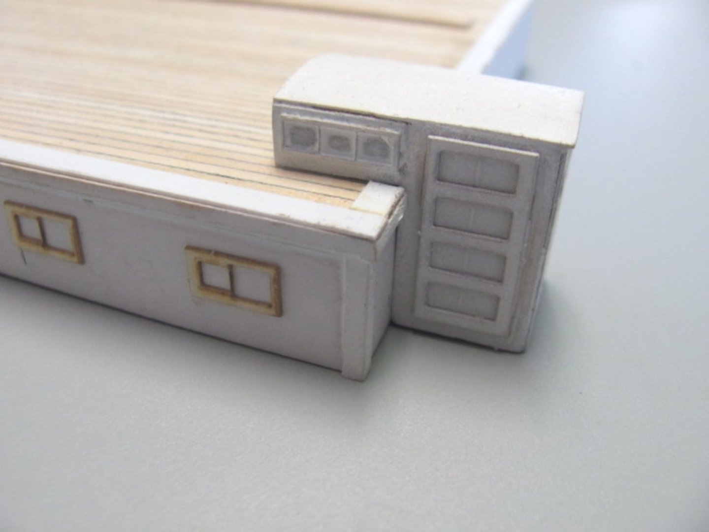
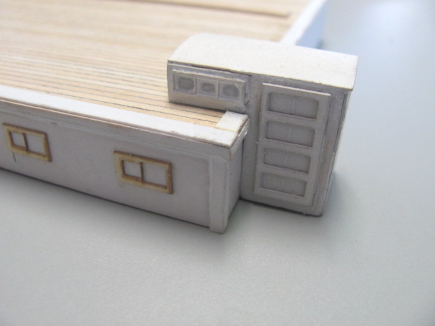
Working on companions and skylights this week. This is the mostly finished aft house. Still have to add the skylight and paint the window frames. The large companion has ten laser-cut parts. The gangway comprises four pieces of .015" laserboard.
-
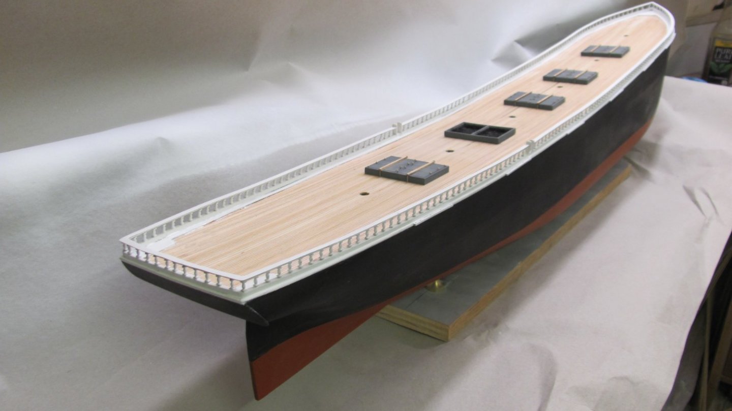
Railings are complete and painted. Have to do a little touchup, but it came out well.
- Bill Morrison, BobG, Paul Le Wol and 15 others
-
15
-
3

(2018_07_2316_35_27UTC)(2020_01_2301_21_01UTC).JPG.8c91c1df2b8986daf6c6e4404113031b.JPG)
(2018_07_2316_35_27UTC)(2020_01_2301_21_01UTC).JPG.c795c82ba2a7de4fadff858d772a58df.JPG)
(2018_07_2316_35_27UTC)(2020_01_2301_21_01UTC).JPG.34e6f553dd1b90600ada2fbe32c63d29.JPG)
(2018_07_2316_35_27UTC)(2020_01_2301_21_01UTC).JPG.9bb1e68597dc63abb2d3e51bb81295ba.JPG)
(2018_07_2316_35_27UTC)(2020_01_2301_21_01UTC).JPG.11be967b56d95a4bf03d360e8e5adef6.JPG)
(2018_07_2316_35_27UTC)(2020_01_2301_21_01UTC).JPG.19f4a026a5ca818196be09a4f9c1a69c.JPG)


Development blogs for new BlueJacket Kits
in Traders, Dealers, Buying or Selling anything? - Discuss New Products and Ship Model Goodies here as well!!
Posted
Lasered the floor boards and thwarts for the boats and bails for the spring stays.