

alross2
-
Posts
403 -
Joined
-
Last visited
Content Type
Profiles
Forums
Gallery
Events
Posts posted by alross2
-
-
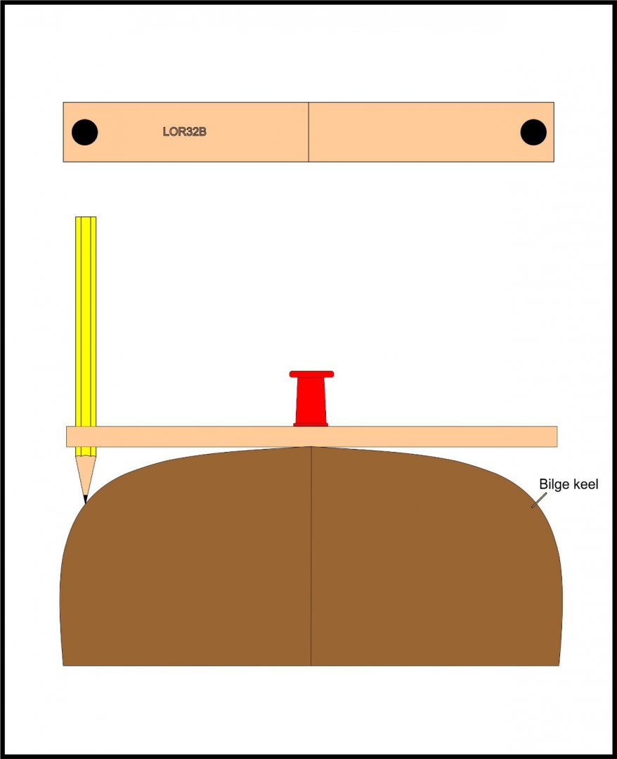
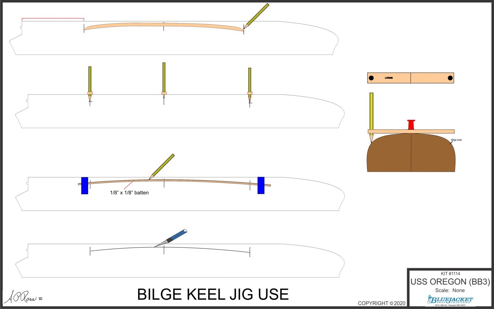
I'm working on the OREGON instructions today and decided the text on setting the bilge keels needed an enhanced illustration to accompany the jig illustration. The dimension from the rudder post to the aft end of the bilge keel will be filled in when I get back to the model in my shop and measure it.

-
-
You go, Mark! If I get a call from someone having a problem with one of the kits I developed, first thing I ask them is whether they read the instructions. If not, I tell them to back and read them, then call me. Because there is so much laser and photo-etch, there is a specific sequence to be followed that isn't necessarily intuitive. I used to develop training materials and procedures for the nuclear power industry and taught technical writing at a college.
-
Let's be honest; not everyone reads and follows instructions. While this isn't a good idea in kits with lots of premade parts, it happens. So, one of the challenges in kit design is to tailor your illustrations for this potential situation. While thinking about the text for this process, I realized that the initial illustration (while just fine if you read the instructions) might be better if it mimicked the text more closely. Thus, the second illustration.
- ccoyle, GuntherMT, thibaultron and 7 others
-
 10
10
-
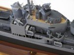
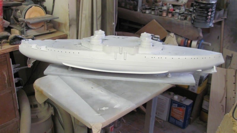
First coat of white primer this morning. Prior to that, I had just mounted the PE torpedo tube covers and the 6 pdr hull casemates and hinges.
- Canute, chris watton, GrandpaPhil and 8 others
-
11
-
-
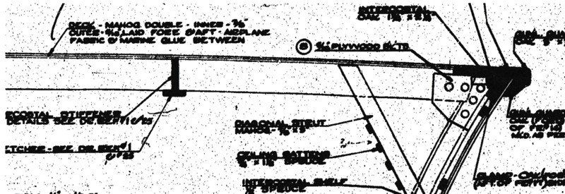
This morning's activity. I had to reduce it to fit the 11 x 17 format, thus the dimensions.

- Canute, mtaylor, GrandpaPhil and 5 others
-
8
-
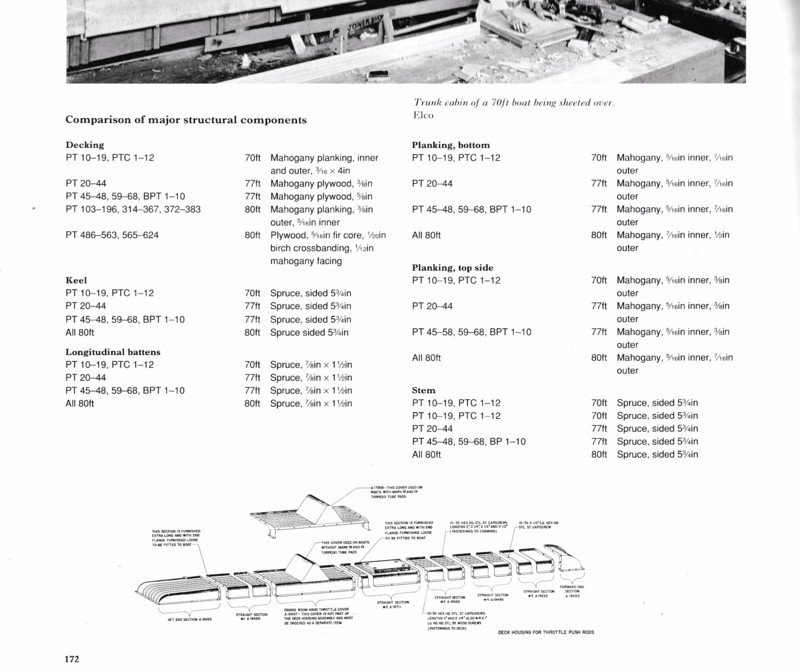
Yes, full length longitudinal planking .
- lmagna, Egilman, Old Collingwood and 1 other
-
4
-
This information is from John Lambert and my ALLIED COASTAL FORCES OF WWII, Volume 2, and was taken directly from ELCO drawings, of which I have hundreds. PT103-196, 314-367, 372-383 had planked decks. PT486-563, 565 on had plywood decks.
-
Not many more drawings to do for OREGON. Finished this one today.
- hollowneck, Ron Burns, Canute and 7 others
-
10
-
I have the following Anatomy of the Ship books for sale. All are the original Conway Maritime Press LTD. hardbounds except QUEEN MARY, which is USNIP. I've had them for about 30 years, but they've only been looked through a few times. The bindings still make that "like new" cracking sound. Prices include shipping by Media Mail. Payment through PayPal only, plz.
The 20-gun ship BLANDFORD – Goodwin, 1988 (ISBN 0-85177-469-5) SOLD
The 100-gun ship VICTORY – McKay, 1987 (ISBN 0-85177-444-X) SOLD
The 74-gun ship BELLONA – Lavery, 1985 (ISBN 0-85177-368-0 SOLD
The Bomb Vessel GRANADO 1742 – Goodwin, 1989 (ISBN 0-87021-178-1) SOLD
The Frigate DIANA – White, 1987 (ISBN 0-85177-356-7) SOLD
The Cunard Liner QUEEN MARY – Watton, 1989 (ISBN 0-87021-599-2) $75
-
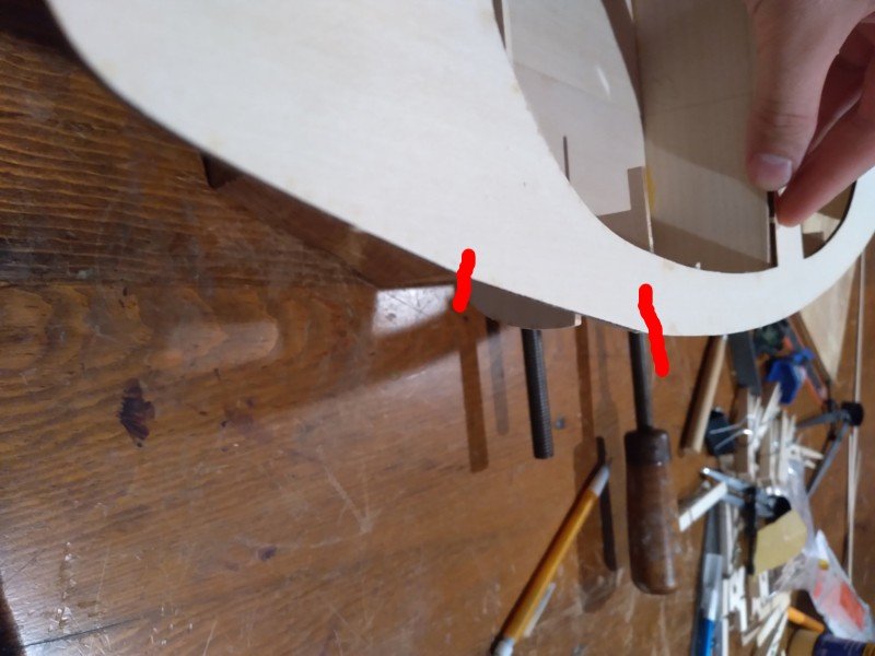
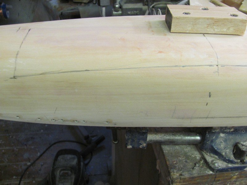
Maybe it's just the camera angle, but it seems like the area between the two red lines is straight rather than an arc. Is it the same on the other side? Scarfing on a short piece about 3/16" or so wide between the lines then fairing it would probably solve the issue.
-
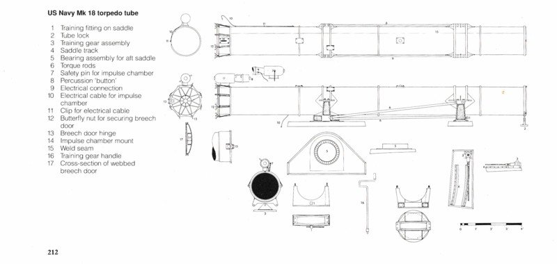
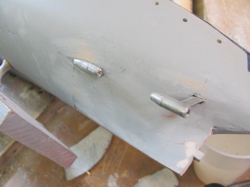
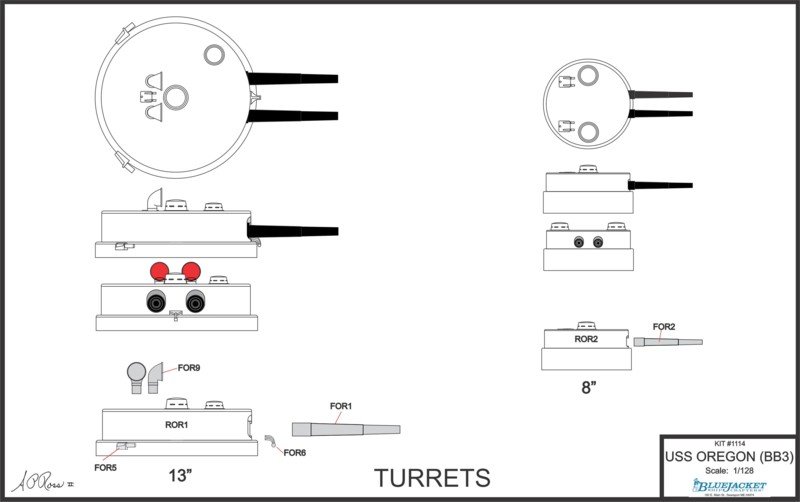
Hopefully, the front torpedo tube slides are not glued on. They're backwards. What's supposed to be the training gearbox is supposed to be inboard.
- Egilman, Old Collingwood, mtaylor and 3 others
-
6
-
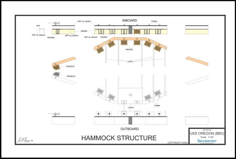
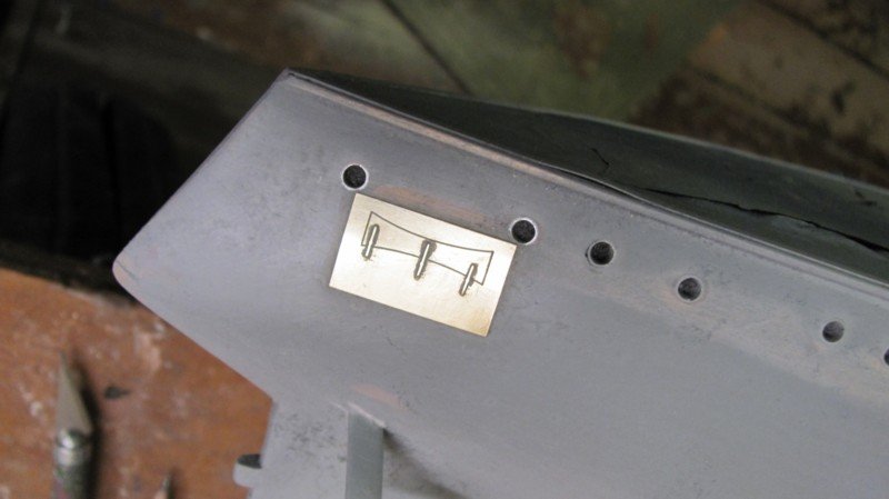
This one required some rework, but should be OK now. It shows the layout of the hammock storage structure. The gunner's grates are only 3/8" x 1/2", but are photo-etched and have the holes completely through. When not in use, they folded down. The pale yellow on the lower section represents silkspan which is used to simulate the canvas curtain over the hammock storage.
- Canute, mtaylor, thibaultron and 6 others
-
9
-
Here's the prop shaft and strut alignment jig in use.
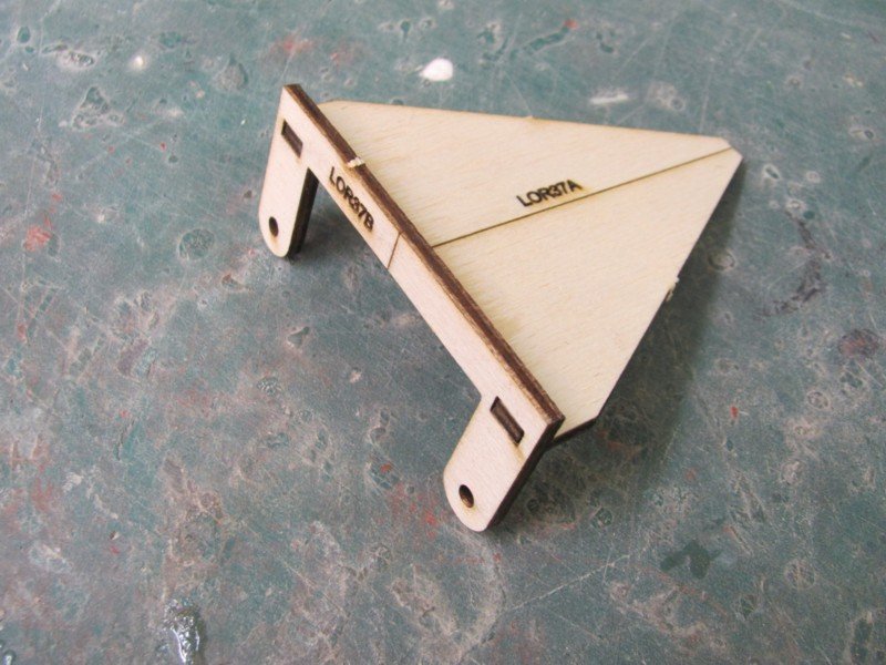
The assembled jig
Aligning the prop shaft boss.
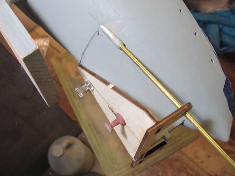
Slot cut for the strut.
Strut in place.
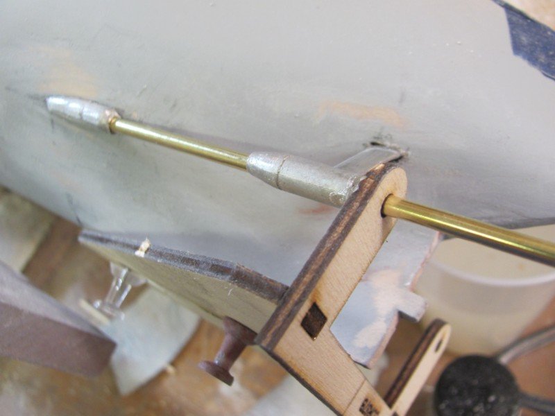
Strut and boss aligned.
- hollowneck, GrandpaPhil, mtaylor and 6 others
-
9
-
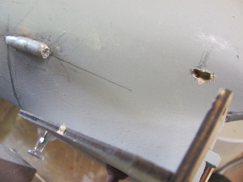
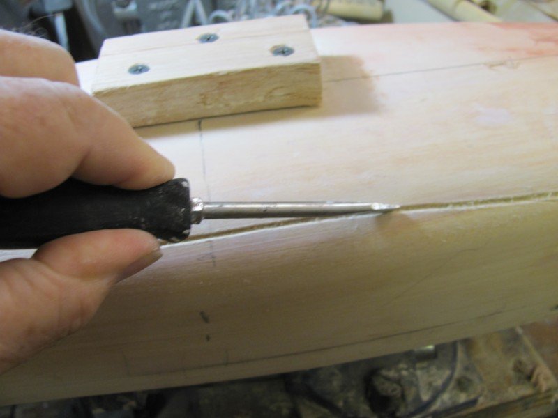
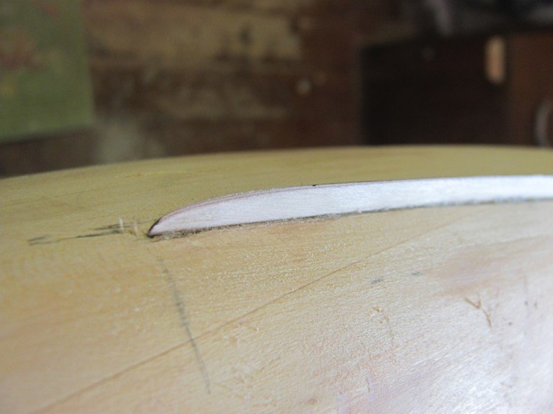
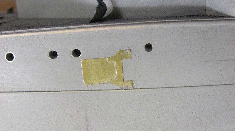
I always cut a slot for the bilge keels as it is sturdier than just gluing them to the surface of the hull. After using the marking jig and using the batten to form a fair curve, I cut along the curve at about a 45 degree angle with a hobby knife, then use a slot head screwdriver to widen and deepen the knife cut to 1/16" or so. If you take you take your time and don't force it, the screwdriver works well. Once the slot is incised, you can dry fit the bilge keel in place to ensure fairness, adjust the slot if necessary, then glue the bilge keel in place. A bit of filler will take care of any resultant gaps.
- mtaylor, GrandpaPhil, hollowneck and 5 others
-
8
-
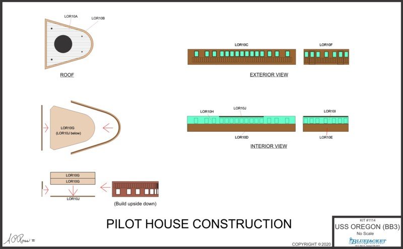
The pilot house itself is not a complex assembly and is built upside down over a form. The angled cuts at the back of the form are to prevent the sides from sticking to it when they are glued together. The sides are .015" laser board, which bends well. The bluish green items are clear styrene strips which will be inserted after the pilot house is assembled and painted.
- GuntherMT, GrandpaPhil, thibaultron and 5 others
-
8
-
Another of today's creations. This shows the jig used for aligning the prop shafts and the prop strut arrangement. Keep in mind that there will be associated text in the manual.
 3Will Day and 2 othersSeen by 9
- GrandpaPhil, lmagna, mtaylor and 7 others
-
10
-
I do like jigs. This is a simple one I created this morning, but it will be a time saver. It is for locating the bilge keels on the hull. When viewed from below, bilge keels run parallel to the keel. Because of the shape of the hull, when viewed from the side, they usually form an arc and this is sometimes difficult to achieve correctly. To use this jig, you place the line on its center on the centerline of the hull, drop a pencil through the holes and mark the position of the bilge keels along the hull at each end and the center of the bilge keel location. You then use a batten and pencil to connect the dots and it will give you a fair curve.
-
Another drawing day, mostly cleaning up earlier ones. Here's one.
And the finished version of one from yesterday.
- coxswain, thibaultron, gieb8688 and 5 others
-
8
-
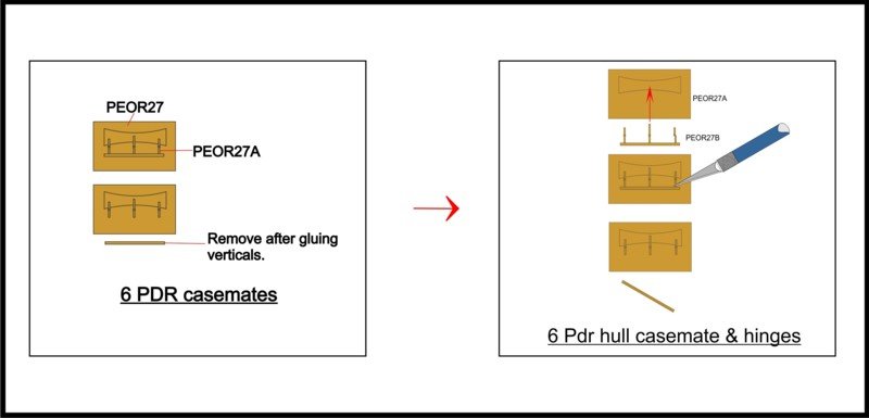
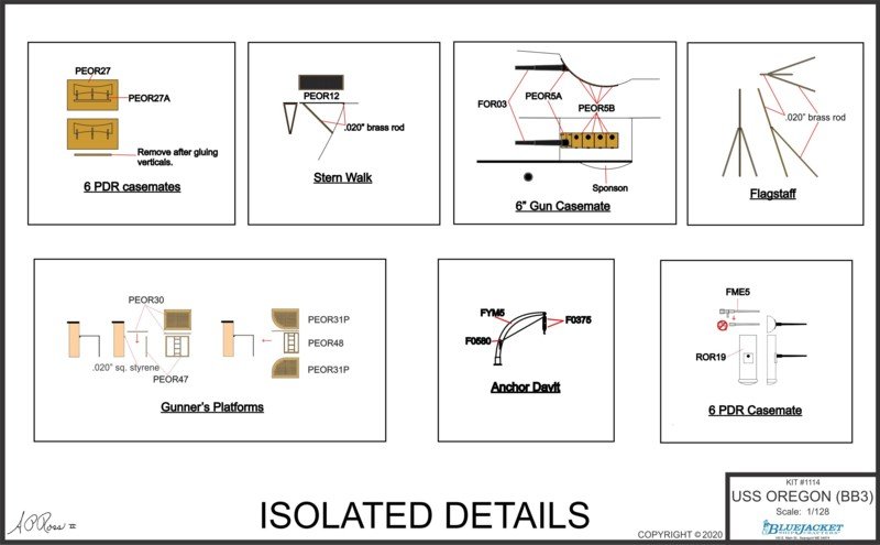
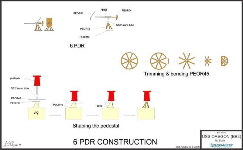
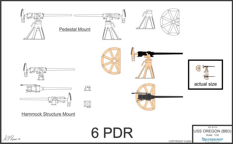
A couple more drawings today. These are for the 6 pdr guns, of which there are 18.
This is in progress and will eventually show the construction details, most likely in a larger scale as no measurements are needed.
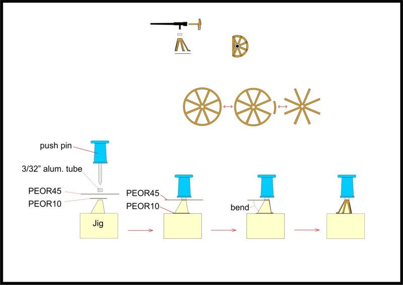
For the superdetailers, I've done these in 1/32 scale, along with an actual size drawing.
-
One or two of the plans will be the normal large sheet (the general arrangement plan is 28" x 40"), but most will be in a spiral-bound booklet of 11" x 17" pages. The drawings on the smaller sheets will be full size, so measurements can be taken directly from them. The smaller size is just handier to use and doesn't take up a lot of workbench space. It also isolates each component, making it less confusing than an overall drawing.
The large sheet (not quite complete) showing the overall model. I still have to add rigging and a few other details.

A few of the 11" x 17" sheets will have a couple drawings due to the small size of the item being assembled/built.
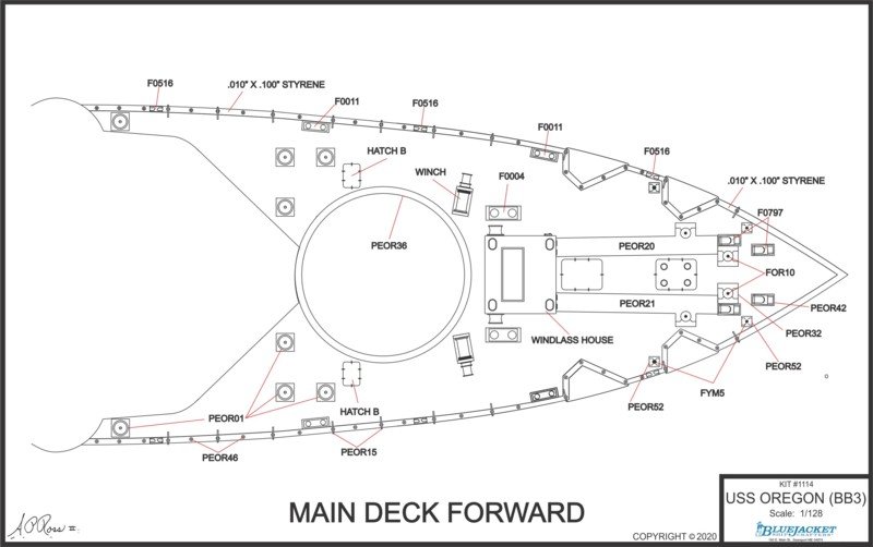
Most of the 11" x 17" sheets will have a single topic to be addressed. Both the main and superstructure decks have the positions of the various components laser-etched on them, making placement a bit easier than trying to measure everything.
-
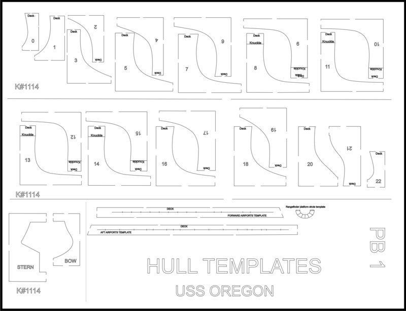
Today is going over the drawings day, checking out what's already done and what further ones are needed. Because this is a solid hull, I'm including hull templates that are laser-cut from poster board. It'll save the modeler a bit of time and expense. In addition to the hull sections, there are templates for drilling the air ports, the stanchions, and a few others. There are two more sheets besides this one, those being the plan and profile with stations.
- gieb8688, thibaultron, GrandpaPhil and 5 others
-
8
-
Starting to attach the brass to the hull.
Aft 6pdr casemate. The hinges are separate.
The various deck hatches and the winch house prior to priming.
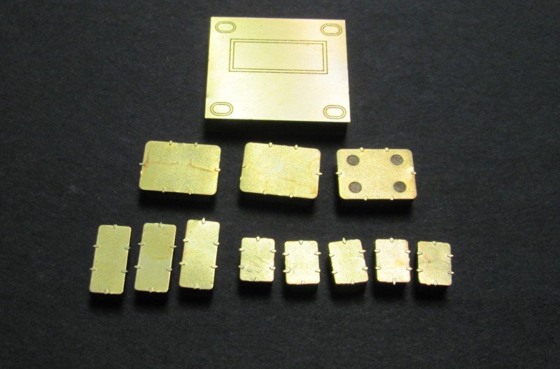
Torpedo tube covers. There are two on each side.
- thibaultron, Canute, mtaylor and 5 others
-
8


OREGON DLOG - developing the BlueJacket kit
in Traders, Dealers, Buying or Selling anything? - Discuss New Products and Ship Model Goodies here as well!!
Posted
The sponsons below the overhang of the 6" casemates are a simple shape but a bugger to get right.