

alross2
-
Posts
403 -
Joined
-
Last visited
Content Type
Profiles
Forums
Gallery
Events
Posts posted by alross2
-
-
-
-
On 4/7/2021 at 1:05 PM, Roger Pellett said:
Al,
What is the scale of this model?
1/128 (3/32" = 1') Same scale as the MAINE and OLYMPIA kits from 2005, 2006.
On 4/7/2021 at 1:57 PM, thibaultron said:Might I suggest some little laser cut ribs, to go inside the gun base, so you can bend the brass stock curves, smoothly? They could then be removed after the base is completed. Perhaps one set could be reused for the other bases.
I may make a resin plug as a bending jig. If that works, I'll include it in the kit.
- mtaylor, Roger Pellett, thibaultron and 1 other
-
 4
4
-
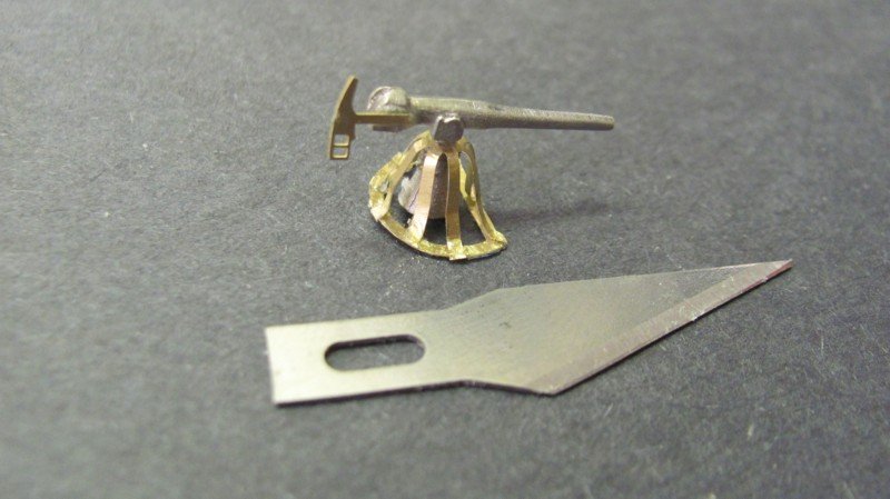
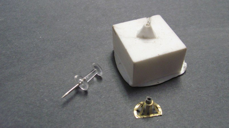
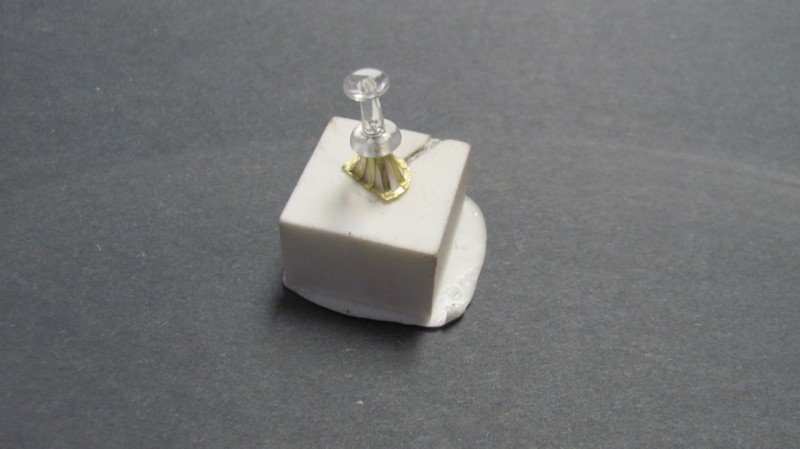
A test assembly of one of the exposed 6 pdr guns, less shield. It's a bit rough, but I was fiddling around with the pieces trying to figure out the best assembly sequence. It came down to lightly gluing the base and pedestal to a piece of masking tape around a stick, inserting the gun peg though the hole on the legs, gluing that assembly to the pedestal, cutting away the arcs holding the ends of the legs, bending down the legs with a hobby knife, gluing them to the base, and trimming them with the hobby knife. The tape is removed from the wood and trimmed away from the gun. It's a bit of a fiddly process, but comes out fine if you take your time.
-
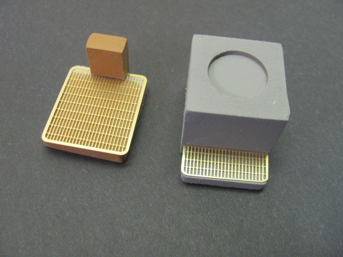
Grates dry-fitted to a couple of the cast resin superstructure deck houses. The houses will be painted buff and the area under the grates black. I may leave the grates in their natural brass for eye-interest.
- gieb8688, nehemiah, Ryland Craze and 8 others
-
11
-
On 3/29/2021 at 9:43 AM, popeye the sailor said:
which catalog is that?
The actual ELCO Parts Catalog for the real 80' PTs. I have a hard copy and also have it as a PDF, along with a PDF of the Higgins catalog.
Al Ross
-
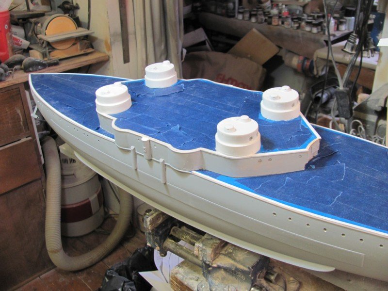
Spent an hour or so this morning masking off the deck surfaces in preparation for painting. It's tedious, but makes painting a whole lot easier, especially if you airbrush.
- GrandpaPhil, gieb8688, lmagna and 6 others
-
9
-
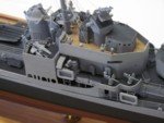
Playing with the photoetch. This is the platform for the aft binnacle on the hurricane deck. There are five pieces and the x bars are recessed. When complete, there will be a cast binnacle and PE rails & vertical ladder.
- thibaultron, lmagna, Canute and 5 others
-
8
-
There are a lot of airports in the hull and little looks worse than a wavy line of them. The kit includes laser-cut templates that are taped to the hull at the deck level with drilling dots that are inline and at the correct depth below the main deck. Once taped in place, an awl is used to mark the centerlines. The holes are drilled out with a 5/32" drill bit, lengths of aluminum tube are inserted into the holes and glued. When the hull is finished sanded, the tube will be flush with hull sides.
-
One of the initial challenges I came across in the early stages was the prominent anchor bills. They are angular and have some difficult angles where the wedge shape meets the vertical walls. I tried carving them into the hull, but wasn't satisfied with the outcome, as they weren't exactly the same. So, I decided to cut a channel across the hull and laser-cut inserts that ensure consistency - worked much better. There are two pairs of lifts that allow the builder some adjustment capability incase he/she didn't shape the hull quite to specs...🙄 The inserts are separate, as well, so the angle can be shaped before they are inserted. Once the basic assembly is complete, the hull is filled and finish-sanded to shape. A laser-cut deck of glued-up decking will be fitted, so the lamination does not affect the appearance.
These are the inserts, before (left) and after (right) shaping.
.JPG.a6f0fd6400dc3a260fa54468346bd5c5.JPG)
Lasered lifts for the anchor bills.
.JPG.939ae28c47fa1c1f05200822d9d829de.JPG)
This is what it looks like much later in the process.
-
The photoetch for OREGON arrived Thursday and I checked it out today, so Tuesday I'll be back on OREGON. The development log (DLOG) for WYOMING will go into hiatus for a bit. The development of the OREGON kit was fairly well along before I decided to create these logs, so I'll be including some prior work just to give you an idea of what transpired before.
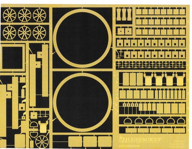
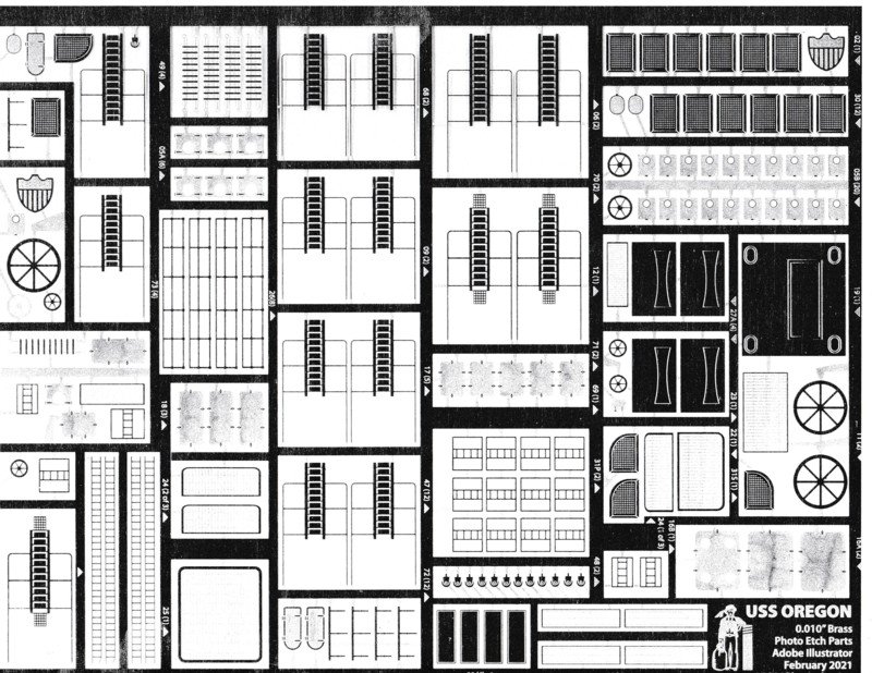
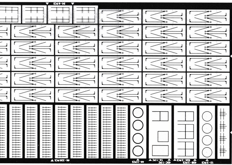
The photoetched brass comprises three sheets: .005", .010", & .020". Here are partial scans of each sheet (reduced):
.005" - turret rings, 6 pdr shields and shoulder rests torpedo tube covers, deck plates for various fittings, crane parts, coal scuttles.
.010" - inclined ladders, gunner's grates, jacobs ladders, bow shield, 6" casemate covers, hatch covers.
.020" - awning stanchions, main deck stanchions, railings, searchlight platforms, binnacle tower.
- Canute, Ryland Craze, ccoyle and 7 others
-
10
-
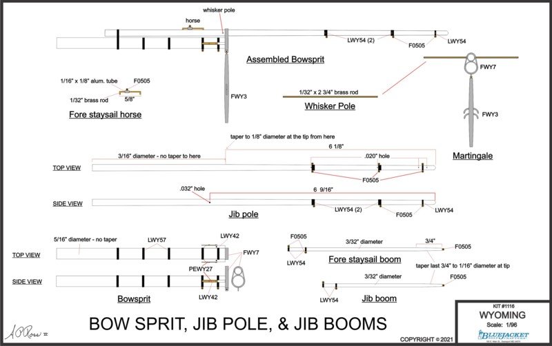
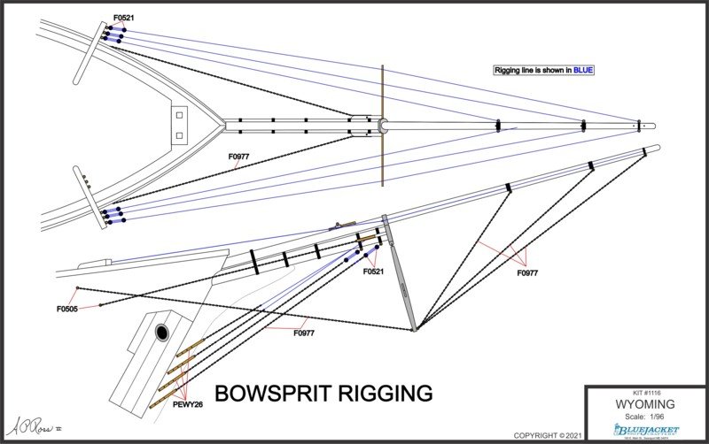
Started approaching the rigging drawings this week. The actual standing and running rigging sheets will be full size showing the entire vessel, but there will also be the isolated detail sheets. I've changed the bowsprit construction sheet a number of times and am finishing up the first iteration of the bowsprit rigging 11" x 17" sheet.
- Kusawa2000, Ryland Craze, Canute and 9 others
-
12
-
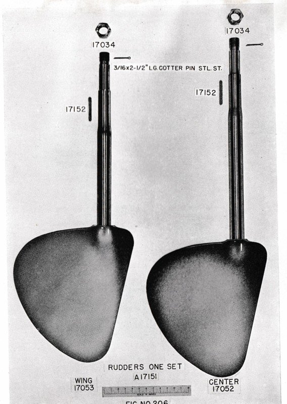
Just as a reference, these are the actual rudders for an 80' ELCO. This is from the ELCO parts catalog.
-
You did a nice job with the joints between the pilot house segments. Like Gary, I love the understated grace and look of these boats.
- FriedClams and pwog
-
2
-
2 hours ago, Kris Haskins said:
The styrene hull came from Sarik Hobbies, although there is someone now producing a very good fibreglass hull in the UK.
Christian Capurro of MTB Hulls. Home - mtbhulls I have one of his 1/24 71'6" MGBs. Top drawer workmanship!
-
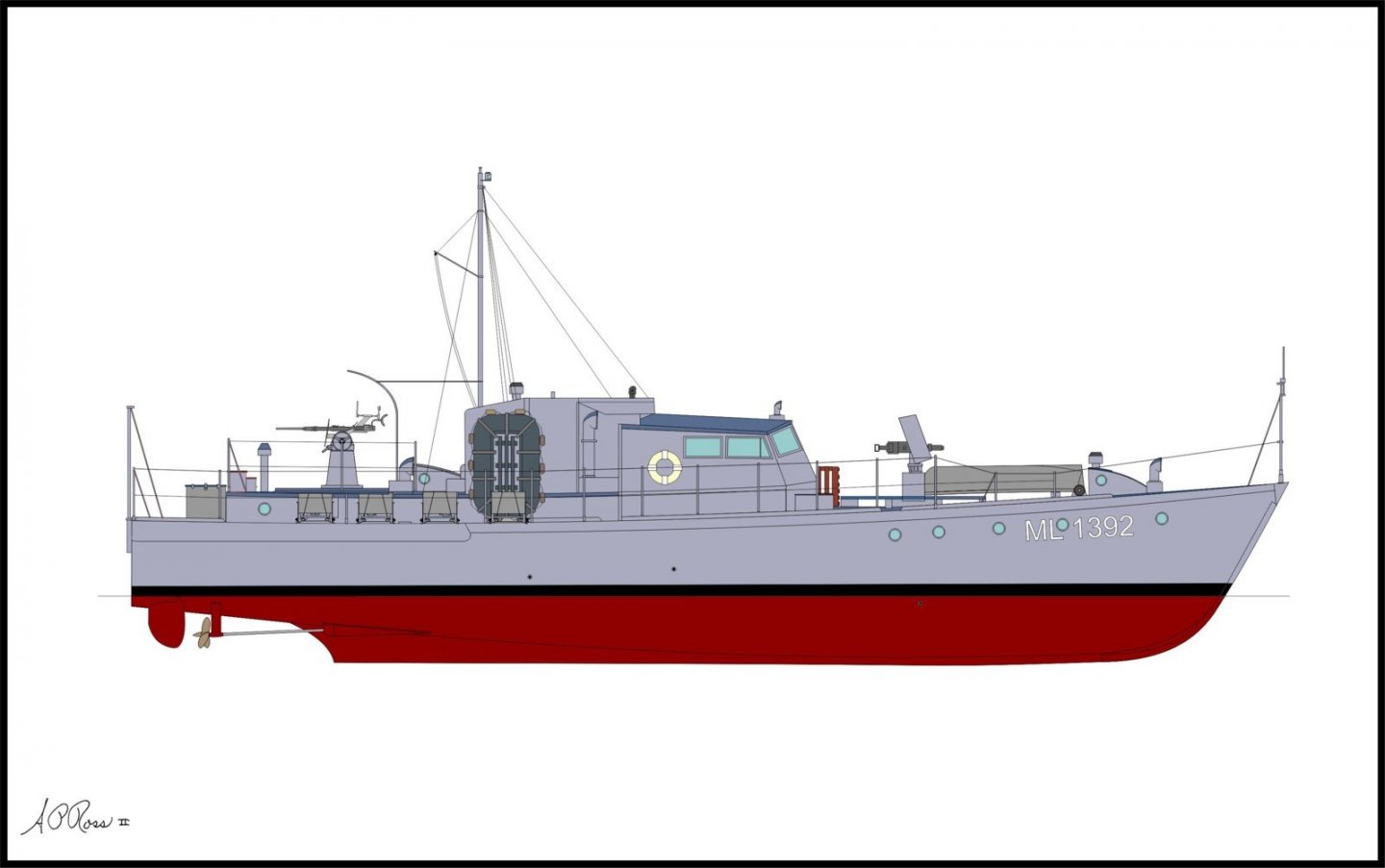
Sister HDML 1392, currently MY SARINDA, which is being reconstructed.
- Kris Haskins, lmagna, GrandpaPhil and 1 other
-
4
-
54 minutes ago, thibaultron said:
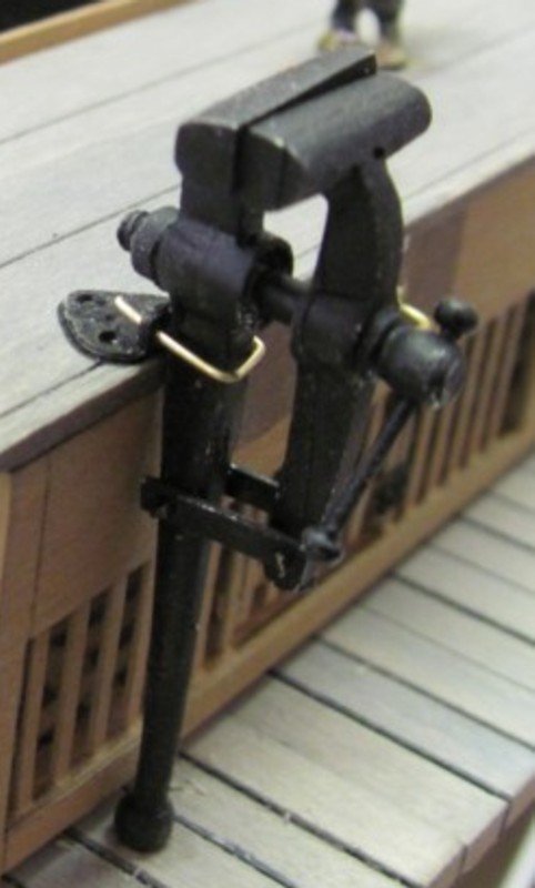
Is the vise for "Pressed Chicken"?
🙄
-
-
The chicken coop was a bit of a fun part. It's mostly lasered and the slats are all panels to ensure consistent spacing. The vise consists of 8 or so pieces and is large enough that you can thread the screw and have it operate.
.JPG.b40641cd1e2ff5032d60131a00d975c8.JPG)
.JPG.4a8625043ba839e8588d4d93c4b566c2.JPG)
.JPG.e7f5321122c9c4dff6108bc44200b799.JPG)
.JPG.e1aab4bbd08aa42ebc401405de6c2566.JPG)
-
11 minutes ago, Ron Burns said:
That sure is a *very* interesting cross section! Amazing woodwork and masonry. The bricks are individually placed and mortar of some kind between?
Ron
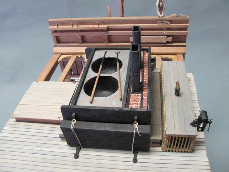
The tryworks consists of a laser-cut wood box with the brick pattern etched into its sides. The individual bricks are lasered from cork. Each course of bricks is laid with a 1/64" spacer to ensure consistent spacing. Once the brickwork is completed, it is sprayed with red oxide primer and, when that has dried, it is grouted with Spackle. Looks amazingly real when dry. They offer the tryworks as a separate kit, too.
.JPG.9eeda6a8e481dcdc10ec361f2c2cc6c6.JPG)
.JPG.a807ab0cb1d46b4e098711a3171bfa09.JPG)
.JPG.e1c3f53280c234a9899fcd249e0a5419.JPG)
.JPG.f3e0c42e76ceaa3ee4c1d03779543ea6.JPG)
.JPG.fc6d3f853c7b9c04233d815fc58be0b7.JPG)
.JPG.28fcfa98aadf31690781fbd11b7f4c4b.JPG)
-
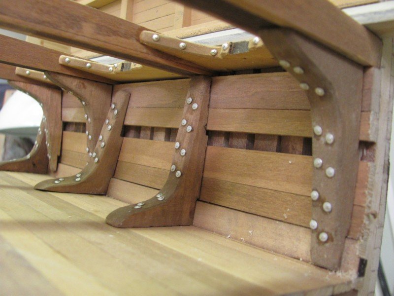
This is one of the more unusual items Nic has had me create. It's at 1/24 scale and is intended to be planked on one side, left unplanked on the other. It shows about 20 feet of the actual hull and includes the tryworks. There are about 800 bricks in the tryworks, so it takes an hour or so to build...🙂
.JPG.0b2fdb9a25f8c62a8156c5b67f613da8.JPG)
.JPG.9abfdfe2ce68666579971c69794df46a.JPG)
.JPG.ea86b6a0ffc40351df9fa557133b077d.JPG)
.JPG.fbfcb174c4e5fd85c50ecbf1109cd158.JPG)

.JPG.b30ec05cd552cdee414d7c9cb1a71dba.JPG)
.JPG.10f243ff9125fd8e44fa237f9c946dbe.JPG)
- coxswain, Roger Pellett, BobG and 9 others
-
12
-
Visit Todd Woofenden's SUBCHASER ARCHIVES site https://www.subchaser.org Many photos and historical data on the WW1 boats.
.
-
You may find these useful when you get to the detail stage.
-
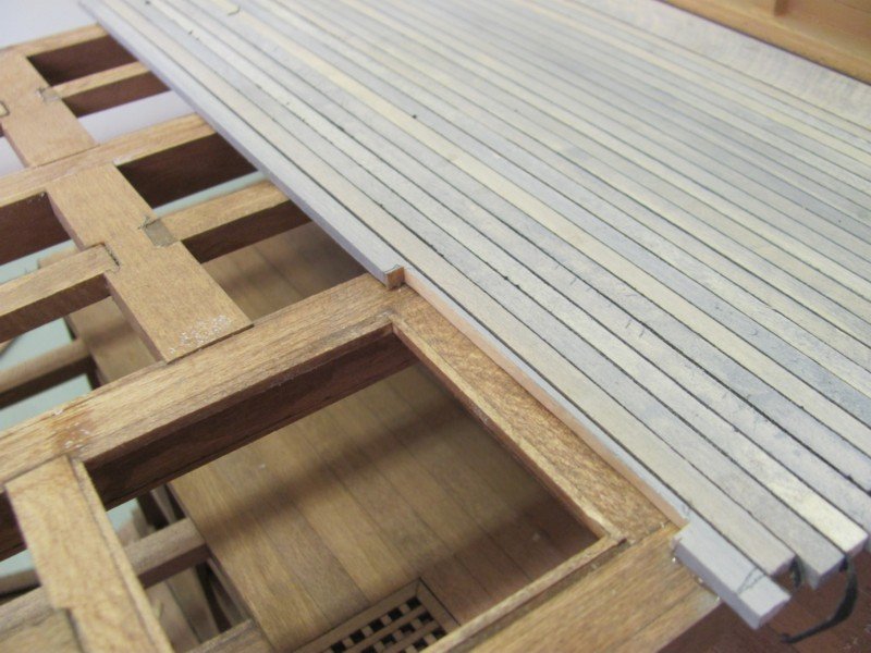
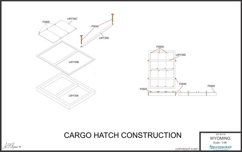
Changed the design of the cargo hatches a bit. They were more complex than necessary. However, the covering boards can be removed individually if the modeler wants to depict a load of cargo in the hold.
- ccoyle, mtaylor, thibaultron and 7 others
-
10
.jpg.d522da60cbed0a397643d1dada06d639.jpg)


PT 109 by popeye the sailor - Dumas
in - Kit build logs for subjects built from 1901 - Present Day
Posted