
Maury S
-
Posts
1,490 -
Joined
-
Last visited
Content Type
Profiles
Forums
Gallery
Events
Posts posted by Maury S
-
-
-
-
-
Several hours of wrapping thread around (Serving?) one of the anchor rings.
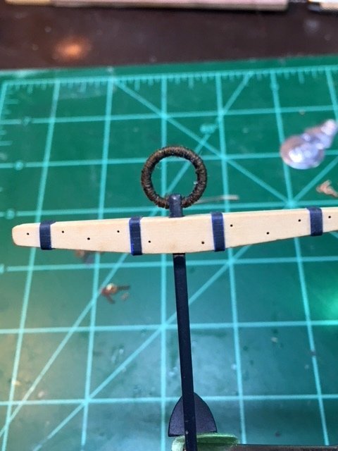
Tedious!
Maury
- davec, Stuntflyer, EdT and 8 others
-
 11
11
-
-
-
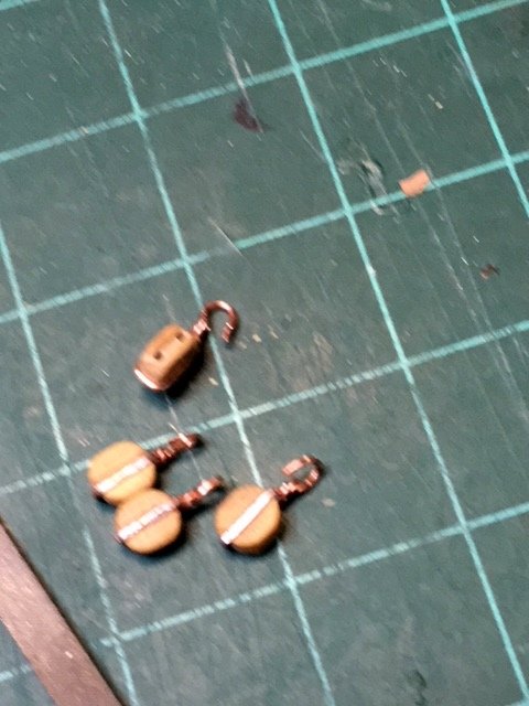
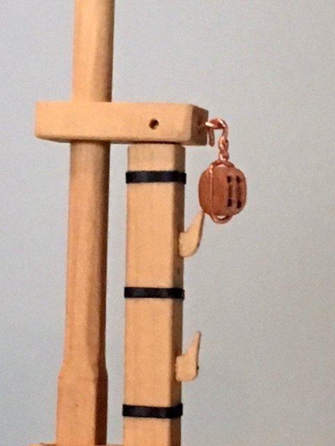
A couple of gun tackles were rigged. They attach to the aft end of the bow sprit to run it out as needed.
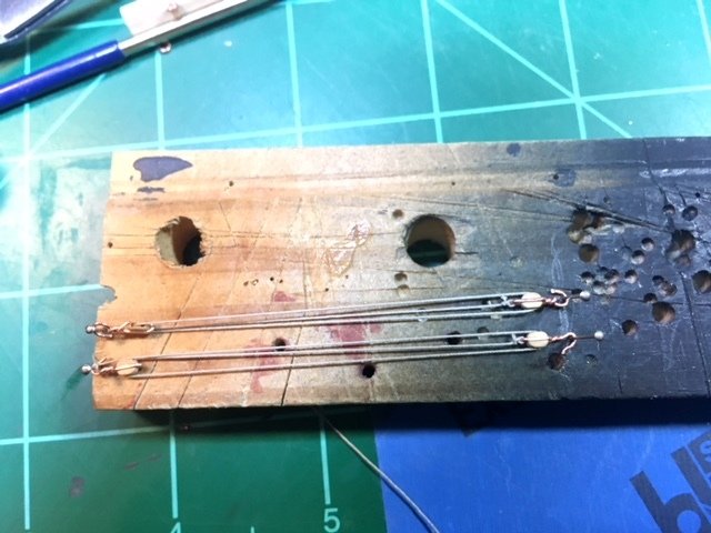
Just threading those blocks was a challenge. Even the needle threader needed adjusting to get it through the holes. I can't imagine how someone working in a smaller scale gets this done.
Maury
-
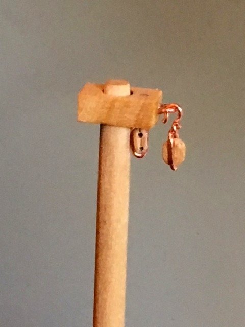
I've finally found some time to work on the model. I made some eye bolts and a few blocks with hooks. The copper is soft even after hardening and too much bending (or squeezing in pliers) creates weak spots. The blocks shown are Chuck's 1/8" box wood singles. The wire is 24 gauge copper stretched to a .021" thickness. The twisted part provides something for the glue to hold onto. The inside diameter of the eyes is + / - .05" = 2.4" at scale.
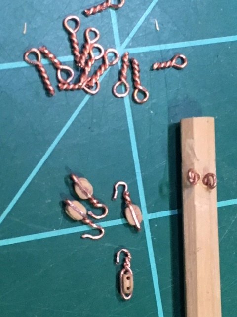
A little more practice is needed for the hooks.
Maury
-
I finally received the spool of 24 gauge copper wire. I hardened a couple of 3' long pieces by holding one end in the vise and pulling the other end until the wire broke. It's interesting to see how much the wire stretches before it breaks. Thanks to Ed Tosti for the instruction on hardening the wire.
Maury
-
-
I replaced the cleats. Using a #76 drill bit I set holes through the cleats. A piece of 24 gauge copper wire was then glued in to reinforce the cleats.
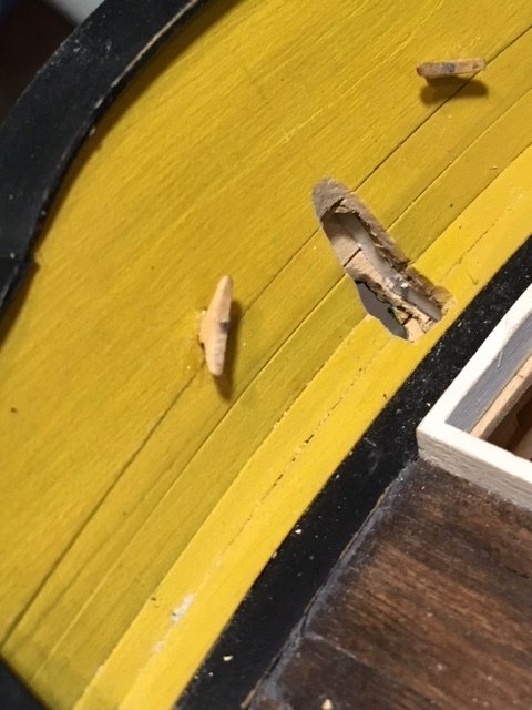
I started working on some blocks. After inspiration from Ed Tosti's recent YA post, I file the copper wire on the side of the block flat. Looks much better!
A problem may have been discovered! A magnet holds fast against the spool of copper wire. It's probably copper coated steel wire. Is this going to be an issue? Do I need to find some pure copper wire and replace what's been used?
Maury
-
-
Dan, No problem. You were correct and that gentle nudge is is always helpful.
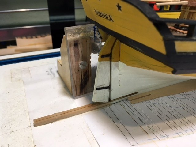
Reworking the rudder meant the post was further aft and the hole had to be enlarged. While I haven't seen any details on other models or diagrams in books, I suspect that access to the rudder post would have been necessary. The plate is temporarily set in place and has (simulated) screws for removal.
I'm still working on a lot of details before I step the mast and bowsprit. Assorted cleats eyebolts need to be installed.
Maury
-
Swan-Morton (non sterilized) carton of 100 will last a VERY long time. I've had no problems using them in an X-acto holder. If there is any question of sharpness after some usage, replace the blade.
Maury
- Canute, mtaylor and thibaultron
-
3
-
I made a new rudder, making sure the axis of rotation proceeds from the line of pintles (not installed) through the center of the upper portion of the rudder stock.
I'll have to enlarge the hole through the counter. I'll find a way of creating a hole that the plug fits snuggly (is that a word?).
Maury
-
-
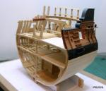
Dan, Thanks. It is a bit awkward and maybe a bit exagerated. See the original drawing https://modelshipworld.com/index.php?/topic/13002-anchor-hoy-by-maurys-pof-harbor-craft-c-1825-148/
There is an off-set in the rudder post. It is a plug-stock rudder designed to minimize the amount of water that can get through. See earlier comments on the rudder:
It actually does swing a fair amount without binding. One of the many issues with working from original drawings rather than actual plans.
Maury
-
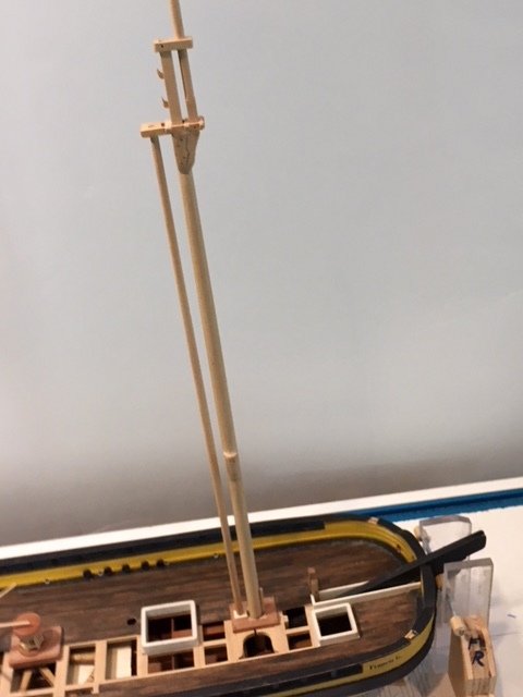
Little things...I temporarily set the mast to establish where the mast step aligns. Wedged into the partners so it sets at the proper rake and plumb sis-to-side.
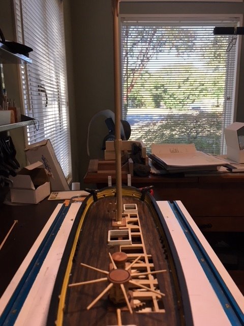
The window frame in the background is my plumb line.
The mast wedges (below) will be put in once I'm ready to permanently step the mast.
Maury
-
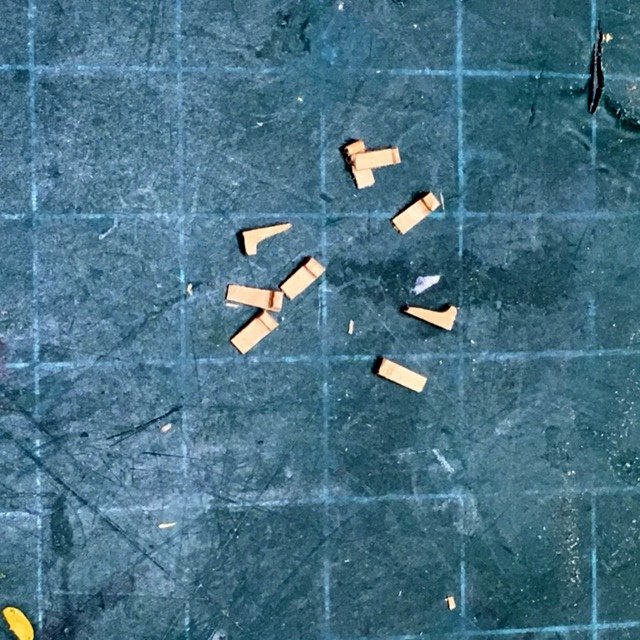
Interesting. Soaking (in water?) seems to be an important part of the process. I tend to crush the ends of bamboo when drawing through a Byrnes draw plate. Maybe using a "parallel pliers" will help that.
Maury
- thibaultron, mtaylor, Bill Tuttle and 1 other
-
4
-
Mike, Looking VERY clean!
Maury
- Stuntflyer, mtaylor and Canute
-
3
-
Thanks Pat, I'll look it up.
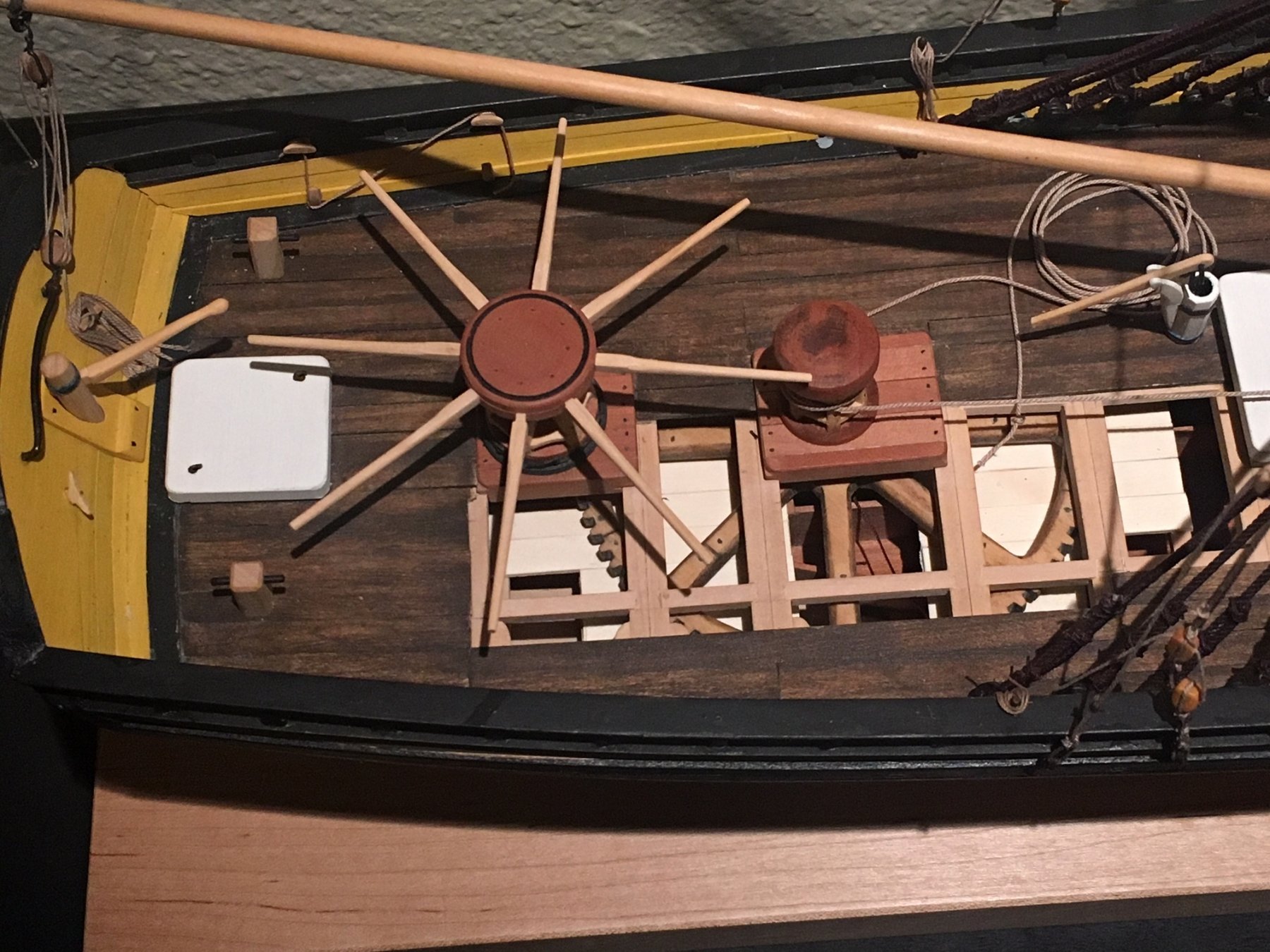
Druxey, Interesting question (among many others). I suspect the capstan was used only while hoisting an anchor and not while under sail. Once lifted, an anchor would be made fast, bars removed (and put in the racks along the bulwarks), and then make their way to the destination.
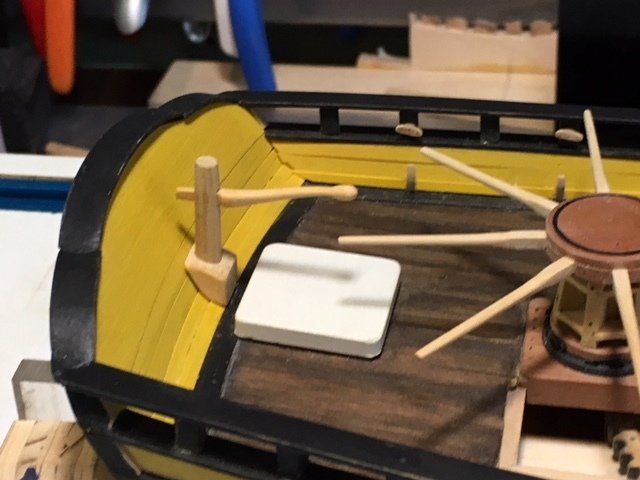
I test fitted the spencer mast and it looks good. The block at the top is not permanent yet so there is room to move it a bit fore + aft.
Another problem now arises. The rigging of the shrouds (20' off the deck) will probably interfere with the hoisting of the gaff and sail. We'll see.
Maury
-
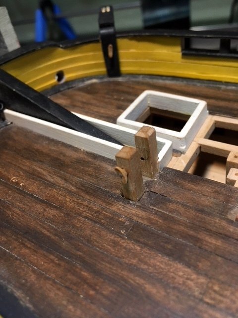
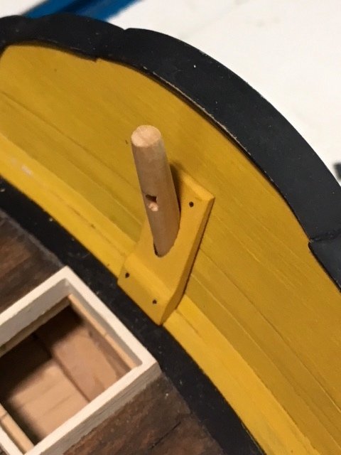
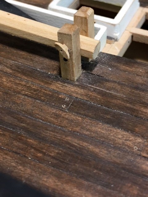
The rudder irons are on, and smeared the paint. No surprise there. Now that they are blackened, would they have been painted over? Minor adjustments needed so the pintles fit easily into the gudgeons.
While I was at it, I test-fitted the tiller. It clears the capstan bars well. Along the spirketing in the background you can see the brackets to store the capstan bars. Cleats above for a line to hold them in place.
Maury
-
-
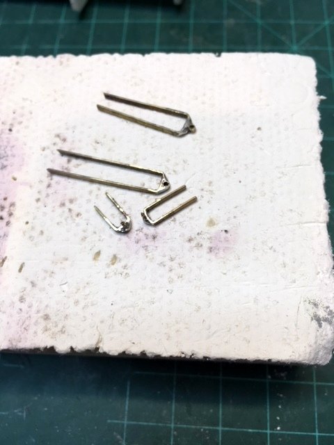
Gudgeons + pintles. I cut and shaped some brass strips. The gudgeon has a small piece of brass tubing and the pintle has a brass rod in the centers for the rudder hinges. I filed a "flat" on both the tubing and rod pieces, dabbed a bit of silver solder on each and held them in place with pins on the magnesia soldering block. Silver soldering gives me plenty of strength for the joint.
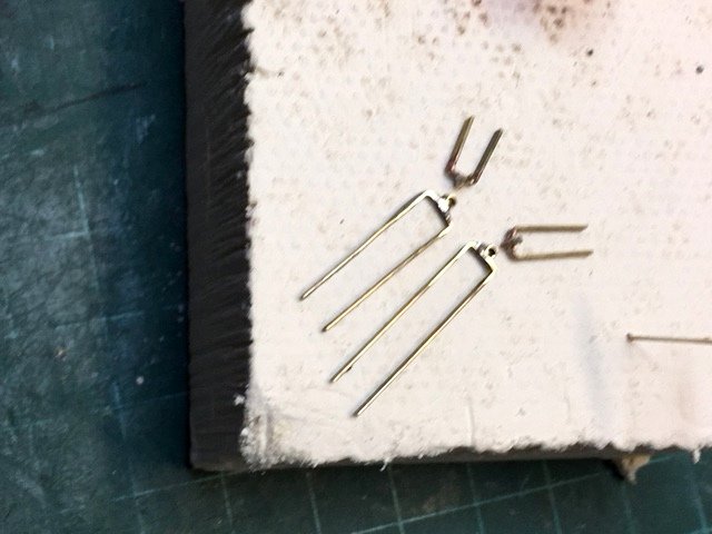
They do not look complete, so I used some low temperature (438 degrees) silver solder (Home Depot, $6) to fill in and make it look more like a casting.
First attempt with the butane torch unbonded the tube so I went to my hot air machine, set it to 440 degrees and it worked well. A little filing and they look better. Blackening next. Getting them to line up on the rudder and hull will be a challenge (big fingers, small parts).
Maury
Going From A 2D Drawing To A 3D Printed Part Tutorial using SketchUp
in CAD and 3D Modelling/Drafting Plans with Software
Posted
TurboCAD has a spline function.
Maury