
AON
-
Posts
2,571 -
Joined
-
Last visited
Content Type
Profiles
Forums
Gallery
Events
Everything posted by AON
-
 ah it works also seems you shouldn't copy and paste
 -
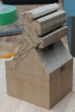
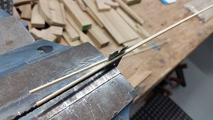
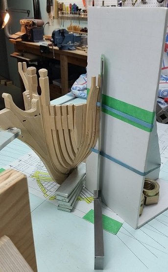
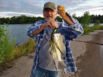
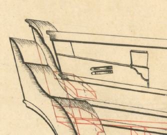
Here we are with summer a happy memory and fall deep in my bones (damp and getting colder). A good summer for fishing, relaxing, and just basically enjoying the outdoors and the sun. Now I find myself back down in the playroom for a few hours in the early afternoon with all my toys. Starting remaking and attaching my forward cant frames earlier this week, so I'll be crawling along on this for a couple weeks. Also stumbled upon some nice bamboo skewers to use as treenails as the others I started making from old bamboo stakes are not so good I also cut out two blank castello blocks for my figurehead carving. I've yet to transpose the sketch widths to the front and rear but I will have enough to keep me from getting bored

-
good morning Druxey I picked your link, copy and pasted each search and hit enter and got nothing. There must be an extra step. help? Alan

-
"The only necessary thing for evil to trumph is for good men to do nothing".
- 364 replies
-
- 3
-

-
- bellerophon
- victory models
- (and 2 more)
-
When I stood by the handrail barrier surrounding that building at ground zero and my host described how people jumped into the canal (that runs along one side) for relief from the scorching heat to only find the water was boiling... I had tears in my eyes... and do so now once again just thinking about it.
- 364 replies
-
- 2
-
-
- bellerophon
- victory models
- (and 2 more)
-
Facinating discussion. The NCO would possibly not have so ornate a head covering. They also would not want it to be too comfortable so as to keep it unoccupied/available. 😆
-
75 years ago today: D-Day -1 My father manned a Bren gun aboard HMCS Caraquet, the flag ship of the 31st flotilla, Canadian minesweepers. They sailed at about 1700 GMT and throughout the night cleared the channel and then in the early morning of the 6th they went to work clearing OMAHA beach for the Americans. Attached is the story, including mention of the moon coming out to temporarily illuminate them to the enemy while they continued to clear the shore. And how they worked through the sun rising until the enemy saw the approach of the massive assembly of ships... and then spotted them. Exactly how my father described it to me except they don't use his words to describe how scared they were the whole time. The 31st Canadian Flottilla - poem.pdf The 31st Canadian Minesweeper Flottilla on D-Day.pdf
-
Oskar24 If I may add, there is the detailed and then the simplified method of doing Plank on Frame. The simplified method does not have scarph joints or chocks in the frames. It might be simple butt joints or even no special joint at all. As the builder you get to decide what you are comfortable doing or want to attempt to do.
-
Potato? ... one persons taper may be another persons angle, but a taper is definitely at a specific angle. (or is it a chamfer?) either way I am buggered
-
Two steps forward.... three steps back. It is the worst dance step ever but leads to one more lesson learnt that will likely never be forgotten. The chocks on the forward cant frames should taper opposite to those on the aft cant frames. It was clearly there in black and white. One lesson learnt some time ago: the second time is always quicker!
-
Thank you Druxey. I will see what I have and hope to give it a try today.
-
Thank you Dowmer. Possibly another trip to the dollar store is in order. 😉
-
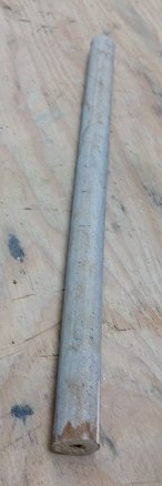
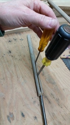
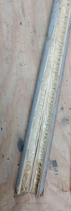
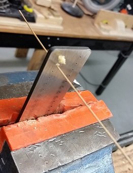
Making treenails (or trunnels). I've searched online, through my small collection of books, and in this forum to find instructions. Allow me to add my take on making treenails with a draw plate. If I have done anything incorrectly I trust one of the more 'weathered' people on this forum might set me on course. First I borrowed (long term no return basis) about a 10 inches (25 cm) in length of bamboo from the garden. This stuff has spent the winter in the garage and is well dried out. It needed to be split and as I am trying to be less of a hazard to myself I did not attempt to do this with a knife. I used three slotted or flat blade screw drives as wedges and split it as I use to split large logs for the fireplace (but without the sledge hammer). Once opened up I could easily identify the soft inner core and the hard outer shell. I needed strips of the white stuff from between these zones. I put the bamboo against a dog (stop) on the bench and pushed a chisel blade through to make smaller strips. Eventually I had to forego the dog as the strips were getting quite thin. The contract reads the frames were bolted to the deadwood with 1-1/2 inch (3.8 cm) diameter bolts. This would be 0.023 inch (0.58 mm) at 1:64 scale. I clamped my draw plate in my vise using soft jaw inserts to protect the draw plate. Looking at the draw plate I can see numbers from 16 to 59 stamped next to the holes. 16 means 0.016 inch (0.4 mm) diameter and 59 means 0.059 inch (1.5 mm) diameter. I need to draw down to the hole size identified as number 23. The holes in the plate are sharp edged on one side and funnel (tapered inwards) shaped on the other side. The tapered or funnel side faces you. The strip of bamboo is fed into the sharp edged side. Once poking through you grab it and pull! I sanded a taper on one end and poked it through the smallest hole it would fit through. I had read that you pull through the draw plate and can assist by pushing lightly from the other side. Let me say this method works for the larger diameter but as it gets smaller you do not want to try to assist by pushing from the far side as the sliver of wood will buckle, or split and buckle. Also, eventually my fingers could not adequately grip the small strip of wood and I needed to employ small hobby pliers to pull it through the draw plate. This did crush and flatten the end of the wood which I nipped off with my chisel and re-sanded a taper to allow me to feed the piece into the plate. I also found that if you push the lead end of the wood through the funnel side a very short distance, it helps to crush and shape the sliver of wood to assist feeding it into the other side. Presently I have a number of slivers of bamboo at hole size number 33 or 0.033 inch (0.8 mm) diameter. This is about 2-1/8 inch (54 mm) diameter at scale. My first piece at 0.023 inch is extremely tiny and I am not certain how this will add any strength to my joint for sanding my frames. I believe I will stick with the larger size as no one but Druxey will be taking a caliper to my build.
-
I believe the block and sheave are both angled at about 7° or so. Yes they sometimes wrote diameter but meant circumference. Steel's tables for rigging are located here: https://maritime.org/doc/steel/tables/pages/032-ShipOf74Guns.htm Thanks to this forum I discovered the site on JSloane's HMS Bellona build. Yes the Canadian younger generation are more metric but it is still mixed for some industry. I am so close to the states that I hear and see many words pronounced and spelt oddly for the way I was taught in grade school. The good thing is no one will take a caliper to your model so close enough is damn good in most cases.
- 364 replies
-
- 4
-
-
- bellerophon
- victory models
- (and 2 more)
-
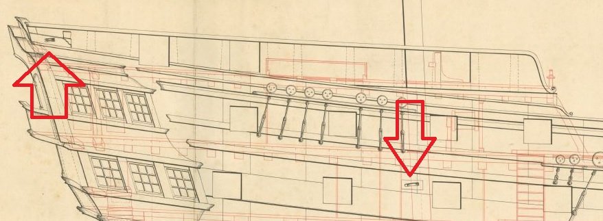
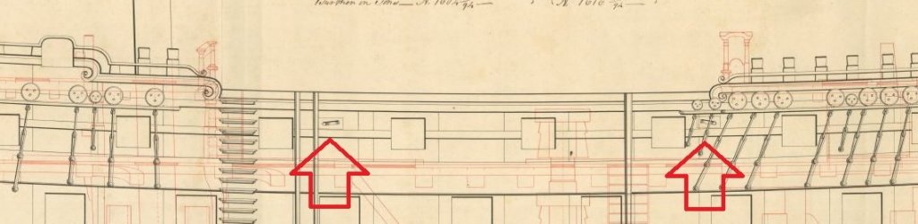
Measured off the plans to the scale on the plans from aft to forward. aft double set of sheaves (see photo below) approx 8" diameter x 1" wide sheave next forward approximately 13" diameter x 2" wide sheave next three forward approximately 9" diameter x 2" wide sheave The best way to size the sheave is to identify the rope that it is used for and follow the sheave sizing rule for the size of the rope. Rope size is the circumference Divide this by 3.1416 = rope diameter Multiply the rope diameter by either 4 or 5 (Lee versus Steels) to get the sheave diameter Multiply rope diameter by 1.1 equals the sheave thickness Add 1/16" to the sheave thickness equals the width of sheave hole The length of the sheave hole is 1.333 times the sheave diameter
- 364 replies
-
- 1
-
-
- bellerophon
- victory models
- (and 2 more)
-
If you really want to go nuts there is another set of sheaves further forward. I can measure these off the print for you if you like.

- 364 replies
-
- 4
-
-
- bellerophon
- victory models
- (and 2 more)
-
If you've only done the pair I am not sure you have gotten them all. This is from HMS Elephant... same as the Goliath... same as the Bellerophon.
- 364 replies
-
- 4
-
-
- bellerophon
- victory models
- (and 2 more)
-
maybe consider some blackening practise runs on some of the drops (cut off pieces).
-
Seems these are more of a guide line than a hard and fast rule.
-
hmmmmmmmmmmmm
-
Quite the conundrum! I've no answer.
-
Of course you are correct... about the trucks not the view of the horse. In my haste to transpose the selected information without recognisable plagiarism I reversed the diameters of the trucks. An unforgivable error. Correction made. Possibly you might moonlight as my proofreader?
-
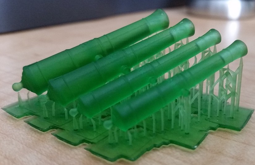
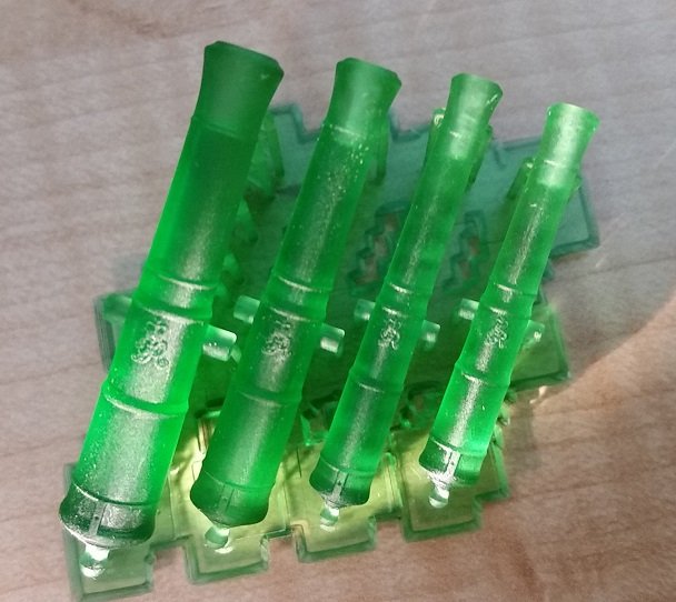
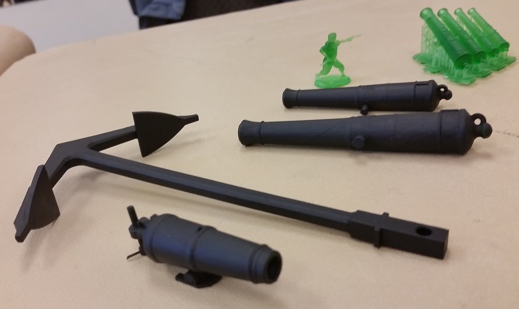
This weekend, after seeing a set of four sizes at 1:64 scale, I commissioned one of our local club members (Model Shipwrights of Niagara) to 3D print me a full set of 74 guns to be distributed as follows: 28 each x 32 Pdr ( 9.5 ft - 55 Cwt) - Lower Gun Deck 28 each x 18 Pdr (9 ft - 40 Cwt) - Upper Gun Deck 14 each x 9 Pdr (short at 7.5 ft - 24.5 Cwt) - Quarter Deck 4 each x 9 Pdr (long at 8.5 ft - 27.5 Cwt) - Forecastle These will be created with his SLA UV acrylic liquid resin 3D printing machine made by Any Cubic Photon. My machine cannot achieve this type of finish and detail at this small scale. Below are photos of the proofs brought to our meeting on Sunday. They are quite smooth, exactly to scale complete with every detail. They can be sanded and accept flat black acrylic paint as he brought in his test pieces. These will go into storage! I also got my hands on a few copies of the Marine Models Magazine dated 1935 - 1939. In some of the issues were very interesting articles about ships' armament written by Mr. A. P. Isard. I will try to describe some of the points I found most interesting.... Ship's guns were originally brass but when replaced with iron they saved 160 tons of weight. The original Royal Navy foundrymen of Kent and Sussex had a steep learning curve prior to achieve trustworthy castings (that didn't burst), smooth true bores (that didn't bend up or down). Prior to the properties of coal being appreciated there was a fight between foundries and shipyards over the trees. It took some time before they managed to get the gun powder mixture correct which saved some lives, but with the increase of quality of gun powder came frequent destruction of carriages. The earliest cannons had no trunnions. Once added they were cast inline with the bore but were later lowered to provide better support and ensure a downward pressure on the quoin upon recoil. Monsieur Gribeauval of France introduced many innovations that were over time adopted by the English Royal Navy: big wheels, iron axle trees, cartridges, elevating screws... all being, where possible, interchangeable. in 1778 the Carron Company introduced the carronade. Merchantmen readily adopted it but the Royal Navy needed to warm up to it for some time (and in many cases they never did!). It was lighter weight, required less powder and a smaller gun crew. With its heavier ball it was more destructive at close quarters. One of the Royal Navies biggest objections were poor fitting balls. Eventually the bores were re-engineered to suit the sizes of the cannon balls. The carriage wheels were called trucks with the aft being smaller then the foreward. This compensated for the camber of the deck and dampened the recoil when the gun was fired. If the gun was place directly aft the position of the wheels would be switched resulting in a raised aft end for the same purpose. The crew was trained to use the roll for the ship to make the gun recoil uphill. The trucks were made of hardwood so as not to damage the deck. Heavier guns had the trucks made in two laminated layers with the grain of one layer being across that of the other. Breech ropes stretched and the two ring bolts acted as guides. Carronade wheels tracked together (inline) whereas the long gun trucks did not. The force of the recoil on the breeching of the long gun caused the weapon to jump; raising the fore trucks off the deck. Available space on the deck did not allow the aft trucks to be moved back to counteract this. Eventually they lowered the trunnions to effectively reduce this phenomenon. The tackle secured to the bulwarks on each side had to be precisely adjusted to equal lengths so as to resist the carriage twisting and injuring the guns crew and gear. The random recoil path of the gun due to many issues, not excluding the unevenness of the deck, maimed many a man. Men were also injured by breechings, bolts and sundry fittings flying around the crew. Guns were most dangerous when fired to windward. When fired the trucks would immediately skid along the deck prior to rotating. Wedges (roughed and tarred to increase the friction) were employed under the trucks when fired ahead or astern to counteract the unequal recoil. And as a final entry a quote directly from the articles: "Carriages were, therefore, a matter of experience and experiment, their sizes, strength and weights being nicely balanced with the weapons they were to carry and, like most things about a ship, a compromise."