Jump to content

Recommended Posts

Posted

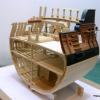
Here is the 5th (port) strake spiled and bent.  It's ready to be glued in place.  One edge is rubbed with soft pencil lead to simulate caulking.

Maury

post-923-0-64915200-1371478499_thumb.jpg

Posted

It's looking good. 5 planks down and only a few to go.


Later 42rocker

Current Build -- Finishing a 1:1 House that I've been building for a while

Current Build -- Triton Cross Section

Posted

Its that last plank that is a bear...or the well fed boa constrictor, in my case.

Chuck Seiler
San Diego Ship Modelers Guild
Nautical Research Guild

 
Current Build:: Colonial Schooner SULTANA (scratch from Model Expo Plans), Hanseatic Cog Wutender Hund, Pinas Cross Section
Completed:  Missouri Riverboat FAR WEST (1876) Scratch, 1776 Gunboat PHILADELPHIA (Scratch), John Smith Shallop

Posted

Aligning the ends of the strakes at the bow has been a problem for me so I now just push a pin through the deepest part of the rabbet at the top of one side to align the top of the opposite side strake.  Remove the pin and you have a nice clean dot. It works for me better than measuring.

Maury

post-923-0-10890700-1371647830_thumb.jpg

Posted

What a great tip, Maury.  That should work on the bigger builds also.  You might think about putting that into the tips and tricks section.

Mark
"The shipwright is slow, but the wood is patient." - me

Current Build:                                                                                             
Past Builds:
 La Belle Poule 1765 - French Frigate from ANCRE plans - ON HOLD           Triton Cross-Section   

 NRG Hallf Hull Planking Kit                                                                            HMS Sphinx 1775 - Vanguard Models - 1:64               


Non-Ship Model:                                                                                         On hold, maybe forever:           

CH-53 Sikorsky - 1:48 - Revell - Completed                                                   Licorne - 1755 from Hahn Plans (Scratch) Version 2.0 (Abandoned)         


Posted

Thanks, I've just posted the tip to the "Tips and Tricks" section.

Maury

  • 2 weeks later...
Posted

A lot more work over the last week.  Spiling and planking is completed.  The sternpost was installed and planks faired.  Now for the insides.  The spacers prevent the bulkheads from being snapped-off so they must be removed.  I drilled a series of holes in the spacers so the isopropyl alcohol could penetrate better.  a couple of applications and they slid right out.  I also drilled the top of the bulkhead to speed the filing of the tabs.  I used a triangular file since it seemed to work faster.  A couple of the frames needed a glue touch-up, but nothing serious.  Working from the middle to the ends, I filed the tabs and snapped the bulkheads out.  The fairing was delicate.  I used a rotary head to take down the frames near the wales and then a cut-off wheel to pare down the keelson.  I've rough sanded (120 grit) and will check thickness before going further.  I think a coat of pre-sanding conditioner is due.  The joints between planks and the treenail heads will be wood putty (see my Echo Section post regarding treenails).  I've got to prevent the putty from staining the wood planks so I may have to get a light coat of poly applied.  Sanding down the tops of the frames will be a challenge.  Any suggestions on how to do that without snapping the little bones?

Maury

post-923-0-84075000-1372688538_thumb.jpg

post-923-0-84466600-1372688540_thumb.jpg

post-923-0-74184300-1372688569_thumb.jpg

post-923-0-44733800-1372688571_thumb.jpg

post-923-0-29474400-1372688912_thumb.jpg

post-923-0-97087300-1372688932_thumb.jpg

post-923-0-42084600-1372689077_thumb.jpg

post-923-0-04023000-1372689777_thumb.jpg

post-923-0-32015800-1372689779_thumb.jpg

Posted

Looking good.  The basswood is so soft that I was able to trim the excess frame height with a single edged razor.  Rotate the hull so that it is at 30-45 degrees from vertical.  This makes it easier to see and gets ones fingers out of the way.  Put a support under the hull and then use the razor to trim the top of the frame.

Toni


Chairman Nautical Research Guild

Member Nautical Research and Model Society

Member Midwest Model Shipwrights


Current Builds:     Utrecht-1742

Completed Builds: Longboat - 1:48 scale       HMS Atalanta-1775 - 1:48 scale       Half Hull Planking Project      Capstan Project     Swallow 1779 - 1:48 scale      Echo Cross Section   NRG Rigging Project 

                           Utrecht-1742

Gallery:  Hannah - 1:36 scale.

Posted

Maury,


Very good. I'm working on the Pinnace at present with the SMSNJ group build. Can you tell me where I can buy push pins like you've been using?


Tom R

Tom Ruggiero


Director Nautical Research Guild

Member Ship Model Society of New Jersey (Past President)

Posted

Tom, Re. the pins,  It's been a long time, but I think I got them at Hobby Lobby (on sale).  Very thin.

Maury

Posted

More progress over the weekend.   I applied some colored wood putty to the seams in the planks where light showed through.  The cap rails were marked-out, cut and trimmed and installed.  The sophistocated clamping system was used to keep the rails even and in contact with the tops of the frames.  Both the sides and transom friezes were sprayed with a dull-coat lacquer before cutting.  To install the frieze, I masked off the sides of the cap rails and everything below the first plank, applied some spray-on contact cement (also on the fireze itself) and stuck it on.  Pretty easy since my top strake shape was taken from a frieze.  The lower rub-rail was tough.  I could not get my box wood cut to the 1/32 dimension so I used the kit-provided bass strips.  It gets painted and is softer, so nothing lost here.  Mircowaving and bending got them into shape.  The transom frieze was pretty straight forward.  Plenty of size choices provided.  Floor boards cut and installed.  The same spacers were used between each board, yet the spaces seem to be different in the picture.  Camera angle?  Finally, the platforms were made (cardboard pattern cut first but some tweeking was still necessary.  I'm shaping the risers (Cleats?) but the red paint needs to be applied to the cap and inner planks before the risers are installed.  Waiting on delivery of more paint since my supply of red hardened in the jar.

Maury

post-923-0-38817400-1373290593_thumb.jpg

post-923-0-84994600-1373290744_thumb.jpg

post-923-0-02995000-1373290762_thumb.jpg

post-923-0-07989300-1373291104_thumb.jpg

post-923-0-38912400-1373291499_thumb.jpg

Posted

Thanks Chuck.  Question on the thwarts...The instructions say 1/8" wide material, the plans measure more like 0.165".  Do you have a preference for the width based on scale??

Maury

Posted

No preference but the wider is more accurate.  The odd size was not available to include in the kit.  I could have made the thwarts 1/8" to match the material I had to work with,  but instead I decided to keep the plan accurate to the original draft.


Chuck

Posted

The risers were cut to the same shape as the first strake...adjusted to fit.  That entailed thinning at both the bow and stern to avoid edge-bending.   I almost miss-read the instruction that says the top of the riser is 7/32" down from the TOP of the cap.  Subtracting the thickness of the cap gives me a size of a spacer to keep the install consistent below the cap rail.  The paint arrived from Model Expo.  The Gun Carriage Red seemed too pink so I mixed some old Copper Bottom Red to dull it down and thinned it substantially.   I'm happy with the color of the first coat.  It is a darker red than shows in the photo.   It's really hard for me to paint an even line along the inside planks, but it will be hidden once the riser is installed.  The thwarts were cut to a .165" width and a bead was scored on one side.  I don't think I will score the other side.

Maury

post-923-0-60903500-1373550762_thumb.jpg

post-923-0-86021600-1373551097_thumb.jpg

post-923-0-35094400-1373551099_thumb.jpg

post-923-0-16104000-1373551321_thumb.jpg

Posted

Risers installed and the thwarts have been cut to rough size for approximate fitting.  The fourth thwart (from the bow) is the wider one to accomodate the mast support.  That piece still has to be worked on.  The front of the transom cabinet was set, marked to match the tops of the risers and installed.  They supports the seats, which is the next segments.

Maury

post-923-0-14560600-1373634753_thumb.jpg

post-923-0-77109300-1373634791_thumb.jpg

Posted

I finished the iron work for the main mast at the thwart.  Just shaping and attach with CA.  You can see the hinge work for the cabinet to the left (too much reflection).  I soldered a piece of brass wire to a thin brass strip,  Then cut pieces to size from the larger sample.  The seats were trimmed and installed for fit.  Then the were taken of for 3 coats of paint, hinges glued in place and re-installed.  Next the knees were trimmed to shape and painted with several coats and installed (along with the mast step).  The knee at the bow needs another two coats of paint. 

Maury

post-923-0-77419300-1373836883_thumb.jpg

post-923-0-53395000-1373837027_thumb.jpg

post-923-0-02339000-1373837118_thumb.jpg

post-923-0-77076700-1373837237_thumb.jpg

post-923-0-87772400-1373837265_thumb.jpg

Posted (edited)

Waiting for paint to dry, I cut out the Rudder and made the Windlass.  The windlass was cut down to 8-sided in the center and on the ends (7-10-7 ratio), the holes drilled and then squared up with a file.  The bars were cut from box wood and came out nice.  One coat of stain (50 - 50 Golden Oak and Natural).  The windlass came out darker and blotchier than the rudder (softer piece of wood?), but the rudder matches the color of the box wood planks which is what I was aiming for.  Does anyone know the proper length of the windlass bars?  I cut them off at 8' but that's too long.

Maury

post-923-0-73944400-1373985870_thumb.jpg

post-923-0-95058300-1373986156_thumb.jpg

post-923-0-99012500-1373986182_thumb.jpg

Edited by Maurys
Posted

Maury,

I hope Chuck or someone knowledgable has the answer on the windlass bars.  I'd think they'd be no taller than a man standing in the boat could use.  5-6 feel long????


Looking super...

Mark
"The shipwright is slow, but the wood is patient." - me

Current Build:                                                                                             
Past Builds:
 La Belle Poule 1765 - French Frigate from ANCRE plans - ON HOLD           Triton Cross-Section   

 NRG Hallf Hull Planking Kit                                                                            HMS Sphinx 1775 - Vanguard Models - 1:64               


Non-Ship Model:                                                                                         On hold, maybe forever:           

CH-53 Sikorsky - 1:48 - Revell - Completed                                                   Licorne - 1755 from Hahn Plans (Scratch) Version 2.0 (Abandoned)         


Posted

I did some metal work yesterday.  Getting a solid connection between the pintle band and the pin was tough.  Four tries before I shifted to a different solder.  I'll clean up the ends of the bands, blacken them and glue them in place.  The rudder needs something.  Maybe some scores simulating multiple boards building up to the current size.  Still interested in anyone's comment about the length of the windlass bars.

Maury

post-923-0-31669000-1374154300_thumb.jpg

Posted

Excellent...


As far as the windlass bars are concerned.  This is a tricky subject as most of the info I have found is for a larger windlass on a schooner or sloop.  But as you guys mentioned,  I kept the bars to within 4-5 feet long.  I made mine 1 1/8" long.  Its just a guess seeing as I never found any actual primary documentation on it.   But if you look at the images of the contemporary model I posted the kit was based on...the windlass bar looks to be about the same size.    I used it as the basis to create mine.  I think your windlass bars may be a bit long in comparison.  Not much though.


Chuck

Posted

Thanks for the comments on the windlass bars.  I think the 4-5' length makes sense (1 - 1 1/4").  I spent time on the irons for the bowsprit.  Getting a hole in the forward piece for a pin into the stem was slow work.  I used an eye for the pin (it's always good to have places to tie lines on a boat).  CA applied under the metal stiffened it up. Leaning the aft iron against the thwart (and gluing with CA) stiffened that one.  I used the sprit to keep the two irons lined up.  I don't think I'm going to rig the boat (space issues) ...just put the spars along side in the display.  Laying all the spars and oars and bars in the boat would hide everything.  I'm probably going to lay four of the oars and the windlass bars inboard.

A bit of a sailing comment.  There is a lot of sail on this boat and no dagger-board or side board to prevent lee-way.  It must have been an awkward sailer on anything but a down-wind run.

Maury

post-923-0-26487800-1374241182_thumb.jpg

post-923-0-01274800-1374241189_thumb.jpg

Posted

The pintles and gudgeon blackened and the rudder is installed.  The tiller is now removed to protect it from breakage.  The dowel provided in the kit for the mast has a huge bend.  No good for anything.  Time to put those Admiralty Masting Workshop lessons to good use.  A center-line is established on two opposite sides.  The proper mast diameter is marked at the ends and three intermediate points on both sides and a good sharp chisel is put to work.  Once the two sides were tapered, the end and intermediate marks were put on the cut faces, lined-out and the remaining two sides chiseled to the lines.  This brings the mast to the correct taper and completely square at all points.  Then the stick is lined-out for cutting to eight-sided (7 -10 - 7 ratio) using tick strips.  Then it went into the chiseling jig and the four-sided stick becomes 8-sided.  Here you can see the eight-sided stick next to the dowel supplied in the kit.  Then a series of 80 - 220 grit sand paper rounds it out, taking care to protect the shoulder at the upper 1/4  of the mast.  A tenon was cut to fit the mast step, sheaves drilled and it was installed just for a good fit.  The photo shows the mast a bit thick, so I'll use the caliper to verify the diameters.  Now to work on the iron work.

Maury

post-923-0-38807700-1374413732_thumb.jpg

post-923-0-74117300-1374413967_thumb.jpg

post-923-0-53724900-1374414152_thumb.jpg

post-923-0-59612600-1374414448_thumb.jpg

post-923-0-91892500-1374414572_thumb.jpg

post-923-0-92419100-1374414724_thumb.jpg

  • 2 weeks later...
Posted

Details added.  Chainplates made per Chuck's method with CA.  Deadeyes inserted and attached to the boat.  I installed the oarlocks and put the boat on the brass support tubing.  I'll cut the length once I find an appropriate display case.  Still have to work on the oars and spars a bit.

Maury

post-923-0-98230700-1375114149_thumb.jpg

post-923-0-93612200-1375114221_thumb.jpg

post-923-0-52641800-1375114240_thumb.jpg

post-923-0-36368400-1375114251_thumb.jpg

Posted

Beautiful work! Before you rig, do not forget to rotate that right deadeye (seen in the deadeye close-up) so the triangle points down. Really instructive build with great photos.

Bill Lell

Posted

Bill, Thanks, they still rotate in the chainplates.  I'm not going to rig it.  Display case size issues.  I'm going to display all the spars in a rack beside the boat.  I really like the model so I may do another for myself and rig that one.

Maury

Posted

Question on oars...the kit provided blanks scale out to 20' in length.  Is this really the size of oars on a 26' longboat?  Maybe they are the same oars used as sweeps on the sloops.  Anyone out there have a good idea of length?

Maury

Join the conversation

You can post now and register later. If you have an account, sign in now to post with your account.

Guest
Reply to this topic...

×   Pasted as rich text.   Paste as plain text instead

  Only 75 emoji are allowed.

×   Your link has been automatically embedded.   Display as a link instead

×   Your previous content has been restored.   Clear editor

×   You cannot paste images directly. Upload or insert images from URL.

  • Recently Browsing   0 members

    • No registered users viewing this page.
×
×
  • Create New...