Jump to content

Recommended Posts

Posted

Hello everybody,

First of all I want to start with some background information on my new model project, the Transom-Model of the Danish ship of the Line TRE KRONER, built in 1742.

The scale will be 3"/8', 1/32.

I have read some literature (source: Danske Orlogsskibe 1690-1860) about the sculptor and the shipbuilder of the TRE KRONER from 1742, which is interesting, as the ship sculptors are often unknown and the creators of the models anyway.

800px-Just_Wiedewelt.jpg.b96f410a1f7d15ff7a7ba8211df94967.jpg

This impressive relief by Johannes Wiedewelt depicts his father, Just Wiedewelt, who was master carver of the royal shipyards on Holmen between 1734 and 1757 and who is the subject of this work.

Unlike many of his predecessors and successors, he was a true master of his trade. There are marvellous marble busts by him of the Danish royal couple Frederick IV and Louise from 1719. Incidentally, the Wiedewelt family immigrated to Denmark from the Thuringian Vogtland, more precisely from Schleitz, in his father's generation.

Wiedewelt prevailed against several competitors in a competition for the post on Holmen and held the post until his death.

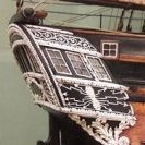
The 1:32 scale model of the stern of the TRE KRONER in the Danish Krigsmuseet is by his hand. The sculptures are made of wax, the hull of the ship of wood.

Heckspiegel2.jpg.e8c4d165bfd4fc110bdccc668a031dd9.jpg

Heckspiegel3.thumb.jpg.0432bebf821e70fb9002f6d5e2bb79dd.jpg

(Source: War Museum staff by email)


The master shipbuilder who designed and built the TRE KRONER as a 70-gun liner was a Frenchman named Laurent Barbé (1696-1754). As far as I know, no illustration of him has survived. He was called to Denmark by the Admiral-General and head of the naval administration Friedrich Danneskiold-Samsøe, as after several scandals, confidence in the local forces was apparently so low that an Englishman or Frenchman was needed to fix it. He was appointed chief designer on 6 May 1740. Barbé seemed to have been a somewhat obscure person. Nobody knows where he came from in France or where he had learnt the art of shipbuilding. Interestingly, French naval historians have never been able to find any information about him in his home country. From the very beginning, there were difficulties in the co-operation between Barbé and the Danish design commission, which had to supervise the shipyard's operations. Barbé had accepted his appointment on the condition that he would not pass on his design methods.

When he was finally asked to explain his construction method, Barbé explained that he had been promised that he did not have to reveal his method and that knowledge of this method was not necessary in order to build according to his drawings, and that he "did not want to publicise what is precisely my science and art, because if it became known, every shipbuilder could do the same as me, which would be one of the most miserable events as a foreigner in a country". It is well known that in several cases he used French drawings, which he could hardly have made himself; he apparently simply tried to adapt French designs, which he had at his disposal, to Danish conditions. In 1744, for example, he was asked to draw a galley. He then submitted drawings that had to be changed, partly because the benches for the rowers were designed for southern Europeans, whose average height was smaller than that of northern Europeans.

He was finally dismissed in 1747. He had married in Copenhagen and therefore remained in the city, where he died in 1754.


Posted (edited)
  • As the historical model was only used to show the stern decorations, I am focussing on that too. The hull segment itself will not be fitted with fittings, and other details but only built as correctly as possible in 1:32 scale in terms of shape, planking and gun ports. This will be the first step in finding a way to build the decorations and figures on the basis of the drawings and with the hull on the table. In order to be able to build the hull segment effectively, I prepared the plans so that the parts can be laser-cut, actually like a kit.Blatt2.thumb.jpg.7e4ad0ae1286c58f3d1b059db1cbdac4.jpg

I built a kind of height-adjustable plug-in parts for the stern, which form the framework for the lower gallery. I can adjust the height and, if necessary, the depth by widening the slots a little. The angle in relation to the vertical should be fine.


8.thumb.jpg.cc6abe238fcf05777c89a1f61ffd9f82.jpg


7.thumb.jpg.1d8de390ca490a94ad6b16329dad5970.jpg


The plank division was based on a comparable Orlog ship in a simplified form (one thickness, not the planking thickness decreasing from bottom to top) for the hull segment.


G1261SchnittBordwand.jpg.58aa813e4cdbd0d53806edfe7b255ddf.jpg


Schnitt.thumb.jpg.cec98de0fa7b519396105fe6ab5b586c.jpg

And here the side-view of the model-section.


Seitenansicht.thumb.jpg.5e50ae524be7771377bbc5b8607a6749.jpg

Matthias


Edited by Beckmann
Posted

In this drawing, the main shaping components are shown in blue here. I have pulled the rear front into the perpendicular, as it is inclined in the view, in order to obtain the actual unfoldings for the components.


Heckansicht_page-0001.thumb.jpg.b8492e46aeb4369cb6af5d72ea428ac8.jpg


I can then use this drawing to cut out the shape of the lower gallery later (material thickness approx. 2 mm), the upper sheet must then be cut from approx. 38 mm thick solid wood, as it is curved and has a material thickness of approx. 8 mm. (25 cm in the original)

Between the penultimate and third-last windows of the lower rear gallery, as seen from the outside, the side wall meets the window front, which then continues over the side gallery. Here, at least the inner window must have been designed as a blind window, if not both outer windows. 


had the parts laser-cut from 6 mm plywood, here you can see the pile of puzzle pieces:

1.thumb.jpg.09bba61ad5ec9ac568cab58e6d47a3da.jpg

At first glance, everything seems to have worked out. The parts are a bit loose, as 6 mm plywood is often not 6 mm thick, but rather 5.7 mm. I should have held the sliding gauge to it again beforehand, but it will work.

2.thumb.jpg.9feeb46966a83b023eeec808efaf44ea.jpg

Everything fits together for now...

Matthias


Posted (edited)

Hello everybody,

the last week, I continued assemblying the bulkheads an gluing solid fillers into the lower-gundeck part. There will be a tiny "black box" behind the gunport.

II-1.thumb.jpg.5c965542bf807ca792983ecb899188d1.jpg

The fillers werd sanded in shape, so the planking should have a nice run.

II-2.thumb.jpg.487849b583872fc4a46007ee6a9e60df.jpg

The more complicated parts will be of course the construction of the quarter-galleries and the stern gallery.

I make the CAD-drawings and test them with paper-templates.

II-3.thumb.jpg.6d0392db8b5ea5ccd0207fcd6627f9b7.jpg


II-IV.thumb.jpg.11373c5afad75e2d6c1b171b46d8ad4c.jpg


So far, everything seems to be okay. But before getting parts to be laser-cut, I need to complete the framing and get the hull planked.


Here you see the procedure of constructing the quarter-galleries.


II-V.thumb.jpg.48b995b004955c0255caa992a6bae8eb.jpg


Matthias


Edited by Beckmann
Posted

Thank you ,


The framing is now finished and I sanded all the fillers and gunport-frames. After that the transom was planked and the opening for the rudder-head was made.

1.thumb.jpg.80fe09f635b53c48e3990e3200d0600a.jpg


2.thumb.jpg.a349c1fc58a688962cbdd95feed4666b.jpg


3.thumb.jpg.709d4fd824a2a51b5476a110aa59bf13.jpg


4.thumb.jpg.df844c2f931c769d972efeda827a001c.jpg


5.thumb.jpg.3a3f180c012f5d5aeb4c32159cf9b28b.jpg


6.thumb.jpg.c1a21f2b07a87015dd32c44bfe8ff40f.jpg

The next steps involve planking the outside of the side walls. Before I start with this, the planking layout has to be precisely defined. In principle, I had already done this in the area of the front bulkhead, but I'll have to check again whether it still works in the stern area.


Matthias

Posted (edited)

Hello Greg,

I know, that the carvings will be the real challenge in this. The rest of the model is just the stage for them. If the carvings don't come out compelling, the whole model won't be.

Ther are two types of carvings, the flat ornament and the figures. I plan to work from bottom to top. So the first carvings will be the flat ornaments of the quartergallery and the transom. I will draw them digitally and get them laser cut in 3 mm boxwood. Then I carve them in detail by hand. Luckily, the plans and photos are detailled and in scale, so that will help a lot.


Wassermann.thumb.jpg.0a788b30dbb5224b5ba3082c47f71449.jpg


Wassermann2.jpg.fafd090d02f771882cd22a32a8d71431.jpg


After that, I  plan to approach the 6 Watermen who carry the balcony. My CAD skills are more in 2D-construction. I don't have the software and the time to make digital 3D-figures. I will propably try different ways. The original model has them carved in wax. One could consider that. Carving wax is still in use for industrial design purpose. 

But these figures would be very fragile. Sculptors use 2K-modelling-clay, this is intersting, because you can form them easily, and carve this afterwards and add missing or broken areas. The third method is of couse carving them in wood. I made more simple wood carvings in the past. I carved animals and other figures for the toy farm of the kids, but this is much more challenging. I will propably try all methods and see, what happens.


Wassermann1.jpg.7729d7c7144e495c9199dfc3dbb5a03a.jpg


Wassermann0.jpg.a07439061a909ae6bc70de17824758b7.jpg


Matthias


Edited by Beckmann
  • 4 weeks later...
Posted

Hello Everybody,


the last weeks I was busy, planking the model. Bending and twisting of planks with dimenson of 2/13 and 2/11 mm was more challenging than I thought ist would be. The curves in the lower areas of the model are very narrow. Here you can see some pictures of the progress.

1.thumb.jpg.b01c93c838e991e7e478e27bfff37294.jpg


2.thumb.jpg.3ccef657e322cf0ffdf5b4621b09036b.jpg


3.thumb.jpg.80b0755a5de22497a3e082104217c413.jpg

After this was done, I faired everything.


4.thumb.jpg.50aa7acbdef12dda780c637008bde07e.jpg

5.thumb.jpg.d5949054e11f8f5ea9542d6f18ea0db9.jpg

6.thumb.jpg.79413a4825177e0e334a4feb60944e9b.jpg7.thumb.jpg.0a66584c5c53ad003a8a5c56e41a572b.jpg

The colours will be like other contemporary models from the Krigsmuseet in Copenhagen. CHRISTIAN_DEN_SYVENDE_(linjeskib).jpg.cf2d588bb6b10cf805c531f051d1c1e6.jpg


Model of CHRSITIAN DEN SIETTE


23fyen.jpg.818faae64d80444b8eab603dfefcc69b.jpg


Model of FYEN


I decided to nail the bright parts of the hull.


8.thumb.jpg.e56bedaa1b44e82d5a2abfff655a1984.jpg

After finishing this, I will paint the black areas of the hull an start building the stern and quartergalleries.

I already made the drawings of most of the parts and tested them on the model and prepared the wood to be laser-cut.

It ist all pear-wood I cut in a garden close to the place to our village. 


9.thumb.jpg.f27b8fed2cc83f4745cde9d96af3b454.jpg

Matthias


Posted

For carving the split-tail tritons out of wood, my inclination would be to carve from the thighs, on up, first, while leaving the twisted lower legs oversized and for last.  Before carving them, I’d make a backing piece that the carving fits into, and temporarily fix it in-place with a glue that could be dissolved in alcohol later.  This support block should have a long enough handle, or extension, so that it can be clamped in a vice for working the fine details.


You have done really beautiful work!  I’m enjoying the build very much.

We are all works in progress, all of the time.

  • 3 weeks later...
Posted (edited)

Hello everyone,
The planking work on the hull segment is now almost complete. All the visible planks have also been nailed and the black surfaces such as the whales and bulwarks have been painted.


1.thumb.jpg.3ab2a4817ea3020975c7d29a4b891041.jpg


2.thumb.jpg.4b69d82b226bdc00cde835bdce8e8212.jpg


3.thumb.jpg.601e66fec9d4fb197825b254f58b6414.jpg


5.thumb.jpg.16f48f1a761012a07748e2e505609671.jpg


The template shows the position of the quartergallery and will later be used to precisely position the horizontal sections of the QG. The sets of drawings from the Danish National Archives are very accurately drawn. There are hardly any contradictions between the actual construction plans and the ornamental drawings. This is very helpful.


4.thumb.jpg.b881bb4d6d8058a77f519e2c1580977d.jpg


Here are the prepared parts for the next construction stages


15.thumb.jpg.0153c0f81d369bf3800180e2d9903397.jpg


The prospectus for the lower gallery windows follows next. It is moulded in advance with moisture and heat.


7.thumb.jpg.2c9a37bc5728f3bdb56f607b302c87bb.jpg

8.thumb.jpg.6cb8c86bdcf419bd3481bcdfe7d04a99.jpg

The first structural elements of the quartergalleries now follow. The curved frame elements form the horizontal structure. On top there will be the fancy moldings. These are curved and also jump back and forth in several positions. That will be fun. The surfaces up to the windows are closed in line with the shape and are later subdivided into individual fields, which are filled with ornamental carvings. The overall composition is very much the French Baroque style and differs a lot from englisch ships of comparable size and age.


10.thumb.jpg.6ceb0a90b218caf86c8bcee0f96f5e2d.jpg

11.thumb.jpg.63a017c7be66723a0aa5da07c745b24b.jpg

13.thumb.jpg.ec7b059cdcf930a05c192e5ccc30256d.jpg14.thumb.jpg.a28f419787b29a37e7dac5b9f0307606.jpg

Matthias

Edited by Beckmann
  • 2 weeks later...
Posted (edited)

Hello Everybody,


just a small update on the construction of the Quarter-Gallery.

I started with the horizontal frames of the construction and added the lower front-panel.

1.thumb.jpg.670f8cebd7ed06ffef02d55d55703dfc.jpg


2.thumb.jpg.51840952152097b60f48d98b3df2fbd5.jpg


3.thumb.jpg.c65df2ce31e11571ea59780c97602017.jpg


4.thumb.jpg.eb3c8351ae7ef52e18e0f6dde11a593e.jpg


5.thumb.jpg.ec021b77bac87158696d78bcbcb1ea24.jpg


6.thumb.jpg.7ccde9ec658eed9de469c83370bf6be4.jpg

Having glued everything to the model, always checking the plans, I added the vertical parts and the seat of ease.

The corner, where the Quarter-Gallery touches the stern gallery is not correct yet. I think now it must be round and not flat. I will overwork that next. It is hard to see this on the plans or on the contemporary model, because it is almost completely covered with the sculpture of the two-tailed merman.


10.jpg.f11e9e6f0ea425f674e493e748243905.jpg

7.thumb.jpg.d299e5a246b15124708e12314fc85098.jpg


8.thumb.jpg.99fd3e7b9f84109e89e56f6f1fd1f3f7.jpg


9.thumb.jpg.3e45fc25f8b2ac2e452020f15c1df71a.jpg


Matthias

Edited by Beckmann
  • 2 weeks later...
Posted

Hello everyone,
Just a small note today, perhaps the information will be helpful for some of you.
The fancy moldings of the TRE KRONER are an important element, so I have been looking around to see if it is possible to get an ornamental scraper wich is more precise than I can achieve by hand with a file and saw.
After several inquiries, I ended up at the company MetallEhrnsberger in Teublitz/Germany, which also accepts such small private orders. I had to send them a CAD drawing of the desired profiles and of course select a material for the scraper, that was all I needed. I chosed 1 mm thick steel, the costs were €40 altogehter. I am very happy with the result. I couldn't have made the scraper that nice.
The material thickness of 1 mm also makes it possible to sharpen the burr several times if it gets a bit round.
I used boxwood as the material for the strips. I had sawn up a supply of it some time ago and left it to dry.


20240224_184539.thumb.jpg.918ec65e479ebe3021b81044531a31ae.jpg

20240401_181109.thumb.jpg.0ab47d34f0feb1e13ce44bd2ef75364b.jpg


20240401_180835.thumb.jpg.f98f877b9518001a4bd4612111d6949e.jpg

Matthias


  • 4 weeks later...
Posted (edited)

Hello everybody,
I'm slowly making progress with the building of the quarter galleries. First Im made myself a certain supply of mouldings. These mouldings have to be prebent. On a scale of 1:32, boxwood mouldings are quite stubborn. Cold bending and clamping them in place is not an option, nor is it any fun, as the slightest slippage disturbs the whole arrangement considerably. Heating with an iron doesn't work with mouldings either. After some try and error, I got stuck with the hot air gun. However, you have to work carefully with it, so that the moulding can be bent and remains in its curved shape, it has to be heated quite strongly, but the surface should not get brown. A moment too long will result in a charred surface. The model in the Nationalmuseet at Copenhagen has painted mouldings, but I prefer to leave them natural.


Here you can see my somewhat primitive bending device.

1.thumb.jpg.9b70bd3d55eb7f09849208ba53aa5865.jpg

The bent moulding is then filed at the ends so that the ends match the profile.

2.thumb.jpg.742a6ef625b0526e2d825c88dc35eb50.jpg


In the corner areas, however, the curves become so tight that bending no longer works.

I used the scraper to round off the middle moulding, which was very tedious. In the protruding corner area of the lower gallery end, I cut a round disc with the circular hole saw, clamped it in the upright drill and inserted the scraper there while the machine was running. The long wood areas turned out well, the cross wood areas can be thrown away. But it only needs a 50-60° cut-out, so it worked.


3.thumb.jpg.1946547a5f2d90e16c00afc03c2faa78.jpg

4.jpg.532cc87cd6ba235a36e4269fa8499cf0.jpg

The lower "drop" of the side gallery was sanded freehand from a piece of pear wood.


5.thumb.jpg.3b1656f71b08f07595e9c79ac15eba6c.jpg

Now a few more photos from the state of construction


6.thumb.jpg.68fa6dff0d07c79489455537827ffbae.jpg


7.thumb.jpg.3c35d4f24d5ef34fc40135b5f5a9eb32.jpg


10.thumb.jpg.3a981fd5b541cc573e827be550b4efe0.jpg

The windows do not fit very well, I will make new ones, now, that the exact shape is fix.

Best regards,
Matthias


Edited by Beckmann
  • 2 weeks later...
Posted

Hello and thank you for your encouragement,
In the meantime, I have made some progress on the lower section of the stern-gallery and added the cornices and surrounds for the parapet panels. The gallery windows have also been partially installed, but still without glazing.

1.thumb.jpg.63a90ab5bdc5c4e846901e952527ddbf.jpg


2.thumb.jpg.23f48cd160cbc101e1b5865a5b8ded49.jpg


3.thumb.jpg.374909f930633a0cf83ea59ea1489201.jpg


4.thumb.jpg.6bd51945538e231e55730f089d15491a.jpg


The basic structure is already quite recognisable. There is nothing new to report on the craftsmanship at the moment; it is essential to create the correct bending radii in advance so that each moulding finds its correct place in the arrangement.
The foliage carvings will later be inserted into the black fields below the window gallery and the arcanthus fronds below the side gallery, but there is still some way to go until then, although my fingers are itching to get started.

But first I'll continue with the interior of the model, the panelling of the lower cabin is laser-cut from 2 mm pear wood, the posts and transoms are placed along the markings. I originally wanted to leave it natural, but now I'm leaning towards painting everything brown-red, like the windows of the rear gallery.


5.thumb.jpg.9af59d7b29516113b6f0a987be2329d4.jpg


6.thumb.jpg.2ae55128c6b0df9dfbb1695f8f97df25.jpg


Best regards,
Matthias

Translated with DeepL.com (free version)

Posted

Hello everybody,

At the moment I am planning how to colour the interior of the lower deck cabin.
I've looked through all my picture books and picked out a selection of interior shots. There are all sorts of things:


Left natural:


20240511_232752.thumb.jpg.f4c9e82b7a22b6f4115660c67b1e4326.jpg


20240511_233002.thumb.jpg.b75b53032c2c505bb4e8f72519d91532.jpg


Or bright blue:


20240512_181559.jpg.9e3fe77d067653b014feebe609b72174.jpg


Or the panelling and rear gallery inside in black:


20240511_232650.thumb.jpg.d1e75bb11a41cbd996cf16b0113e537c.jpg


But also red:


20240511_231913.jpg.c2d6ec5f276c3ee17c743f36b8c7dcad.jpg


20240511_232337.thumb.jpg.e492b41d98888036bc3cd034d3d3601b.jpg


The more detailed pictures are from the Princess Royal, red bulkheads, inside of the stern gallery red, sides natural with red beams and black below the ports, red deck beams and knees:


20240512_165020.thumb.jpg.484c13204525c5d26dd0a9ce47367a86.jpg


20240512_165041.thumb.jpg.78c68c983a88fe1c5c4932b09b51dfec.jpg


20240512_164949.thumb.jpg.6003a4285a4a805741f7618e2be5ecb9.jpg


Is there any more information on this anywhere in the literature?
I actually wanted to paint the lower cabin red, with a stern bench,  rudder trunk  and one or two rows of supports in red under the red deck beams. Then white in the upper cabin.
Nothing has happened yet, here is the status of my work, I would be pleased to receive suggestions for the correct colour scheme.


20240512_191010.thumb.jpg.b6e292921994cfaa3a078f250e173e84.jpg


20240512_190932.thumb.jpg.5f3913c9e47fc2ae9bbccc12603c0ba8.jpg


Best regards
Matthias

Join the conversation

You can post now and register later. If you have an account, sign in now to post with your account.

Guest
Reply to this topic...

×   Pasted as rich text.   Paste as plain text instead

  Only 75 emoji are allowed.

×   Your link has been automatically embedded.   Display as a link instead

×   Your previous content has been restored.   Clear editor

×   You cannot paste images directly. Upload or insert images from URL.

  • Recently Browsing   0 members

    • No registered users viewing this page.
×
×
  • Create New...