All Activity
- Past hour
-
 NW Ship Builder reacted to a post in a topic:
Christiania 1774 by TJM – approx. 1:67-1:64 – Danish Light Frigate based on Vanguard Models HMS Sphinx
NW Ship Builder reacted to a post in a topic:
Christiania 1774 by TJM – approx. 1:67-1:64 – Danish Light Frigate based on Vanguard Models HMS Sphinx
-
 mtbediz reacted to a post in a topic:
USS Constitution by mtbediz - 1:76
mtbediz reacted to a post in a topic:
USS Constitution by mtbediz - 1:76
-
TJM reacted to a post in a topic:
HMS Surprise 1796 (prototype) by James H - Vanguard Models - 1:64
-
TJM reacted to a post in a topic:
HMS Surprise 1796 (prototype) by James H - Vanguard Models - 1:64
-
ubjs reacted to a post in a topic:
Norske Love by ZhangRenWing - Billing Boats - 1:75
-
JacquesCousteau reacted to a post in a topic:
Emma C Berry by cdrusn89 - Model Shipways - 1/32
- Today
-
Tony Hunt reacted to a post in a topic:
HMS Lord Clive 1918 by RGL - HobbyBoss - 1/350 - PLASTIC
-
Tony Hunt reacted to a post in a topic:
HMS Lord Clive 1918 by RGL - HobbyBoss - 1/350 - PLASTIC
-
glbarlow reacted to a post in a topic:
HMS Surprise 1796 (prototype) by James H - Vanguard Models - 1:64
-
 GGibson reacted to a post in a topic:
USS Constitution by mtbediz - 1:76
GGibson reacted to a post in a topic:
USS Constitution by mtbediz - 1:76
-
 It must take some serious masking to use an airbrush as you do. I guess I’ll have to be bold and give it a try with this model. I really detest coppering, after Vanguard I promised myself I’d never do it again, I may not have a choice with Surprise. At what point did you paint the gun ports?
 -
USS Constitution by mtbediz - 1:76
kgstakes replied to mtbediz's topic in - Build logs for subjects built 1751 - 1800
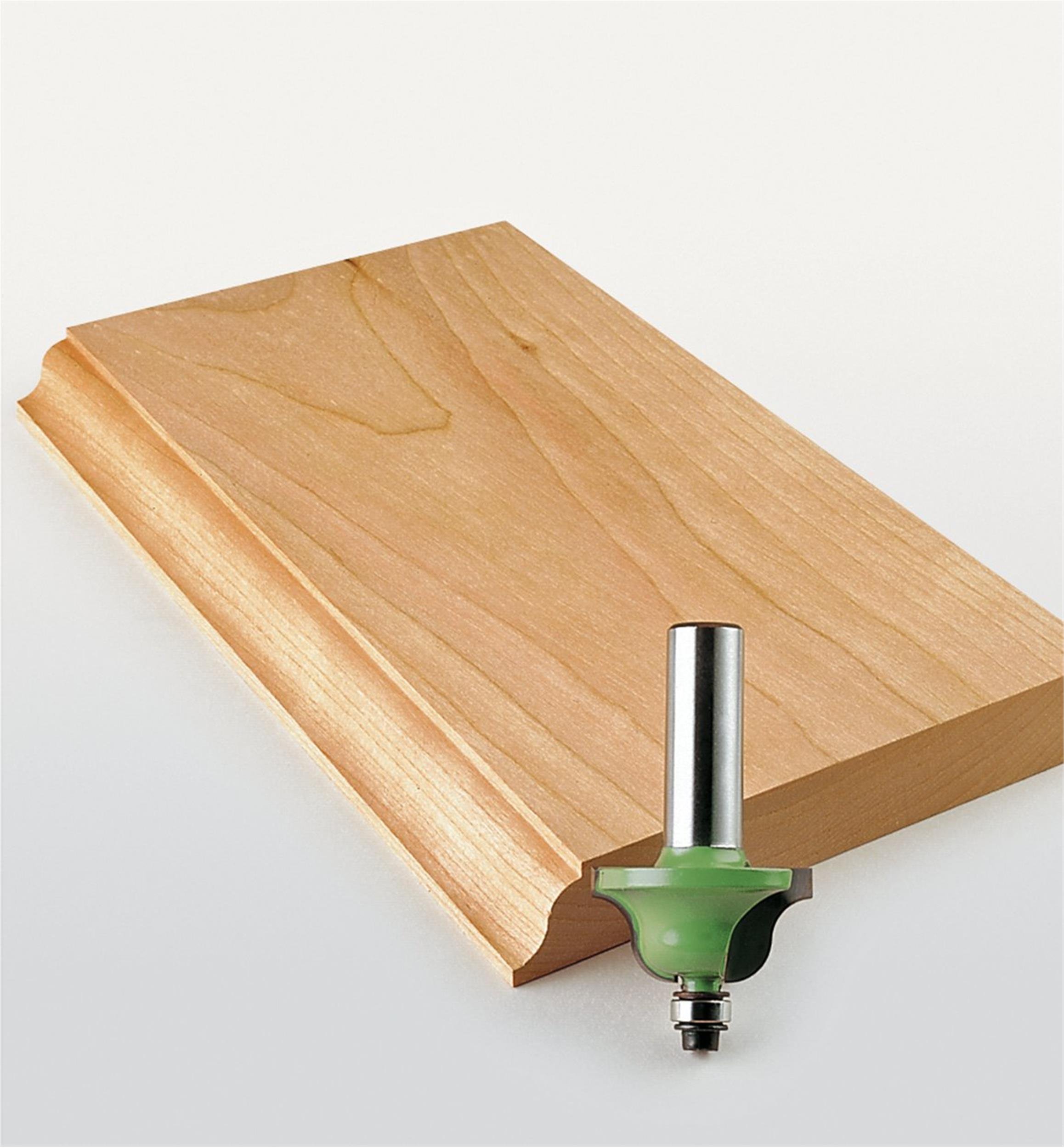
I’m late to the party but maybe a Roman ogree router bit would work Adjust your depth and it might work for you.
-

USS Constitution by mtbediz - 1:76
mtbediz replied to mtbediz's topic in - Build logs for subjects built 1751 - 1800
Thanks, Greg. A modeler wrote in his build log that he couldn’t use the laser‑cut cap provided in the kit because it wasn’t the correct size, and that he had to make it from scratch. If that’s true, when the time comes you can also easily make the cap using this method. -
USS Constitution by mtbediz - 1:76
mtbediz replied to mtbediz's topic in - Build logs for subjects built 1751 - 1800
Thank you very much for the photos, Jon. They are wonderful and very helpful to me. Do you have a photo in your archive showing how the flying jibboom is connected to the cap? Thanks again. -
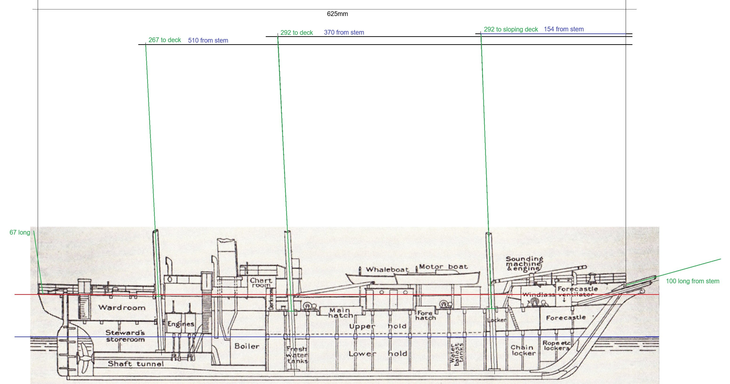
 Comparing plans to a photograph. According to the photograph, it seems that the rigging plays a role in how the mast leans.
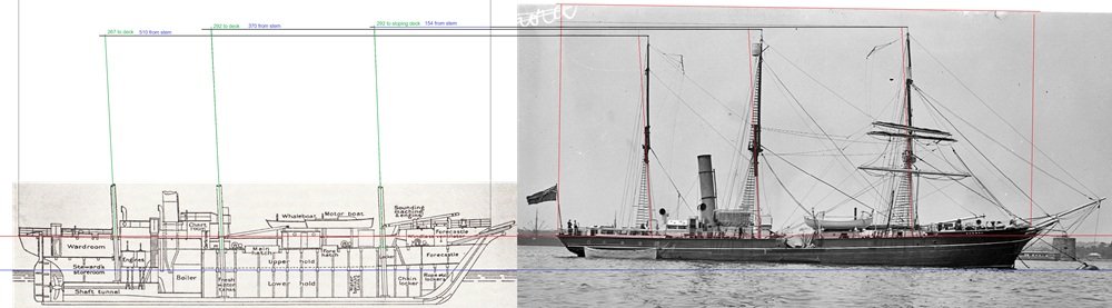
-
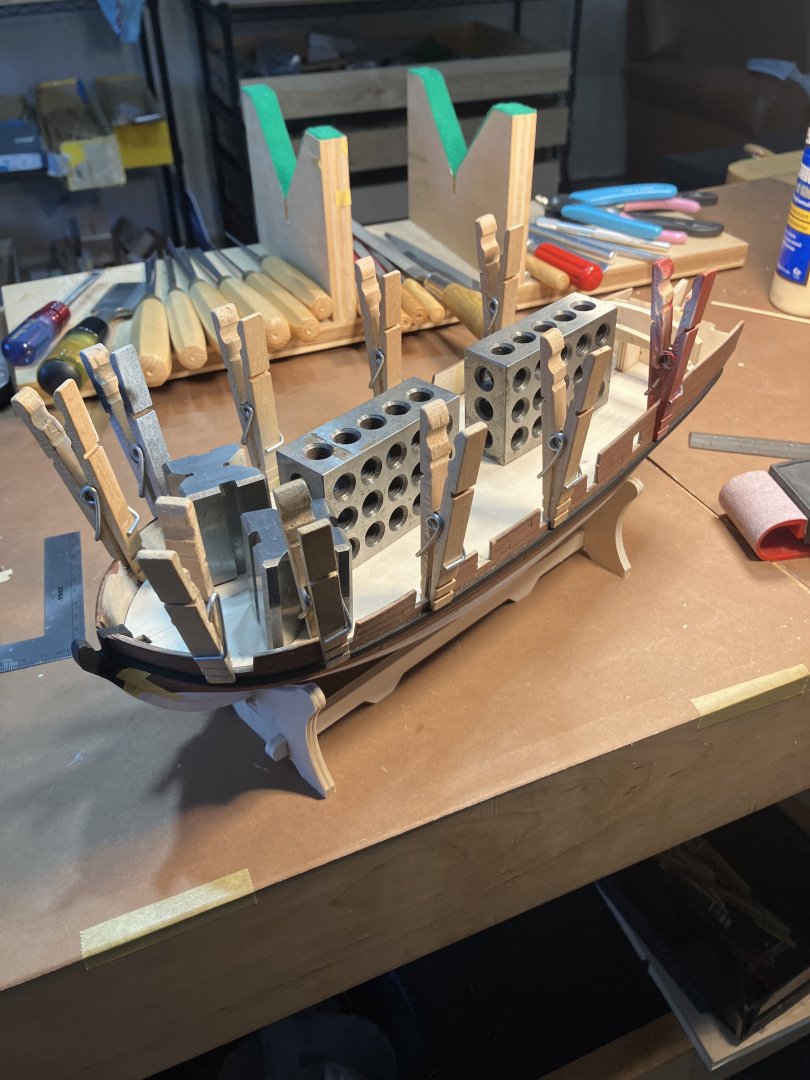
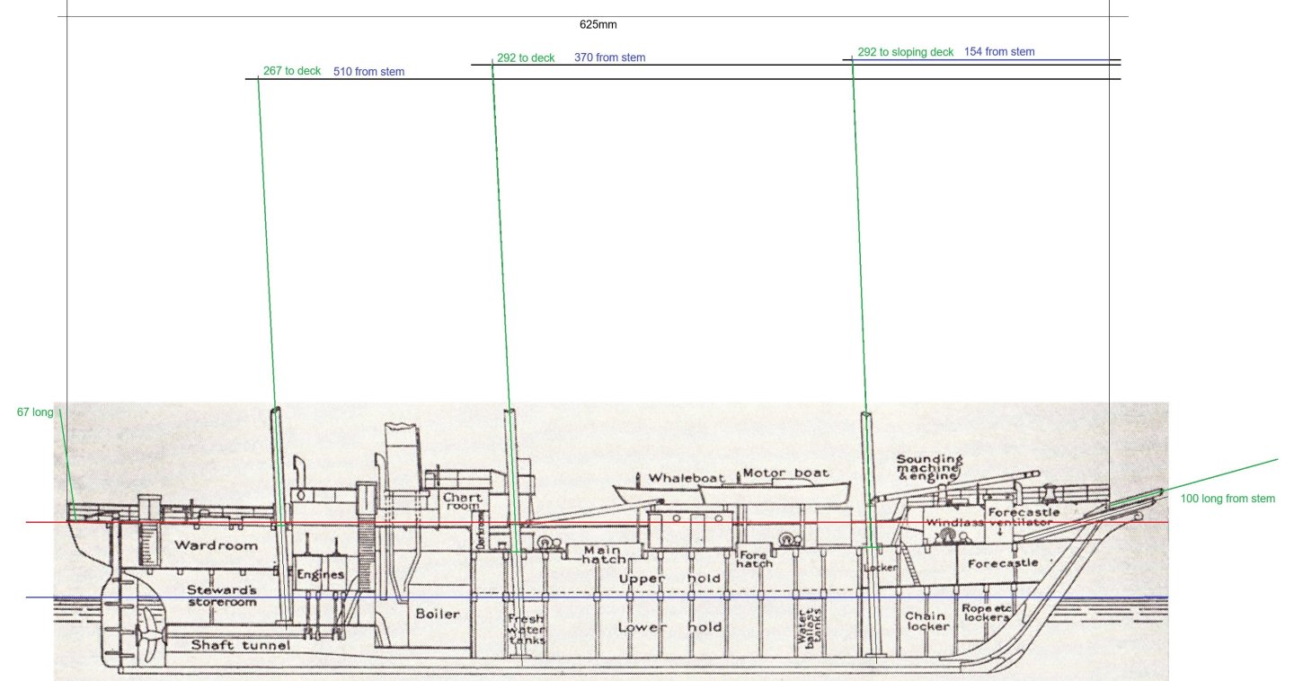
 So a day spent in research is never wasted. I've identified what I'm missing and still trying to figure out the capstans which I think might be a steam winch on deck more than a capstan.
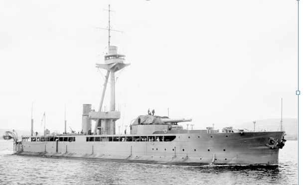
- 5 replies
-
- 1
-
-
- Lord Clive
- HobbyBoss
- (and 1 more)
-
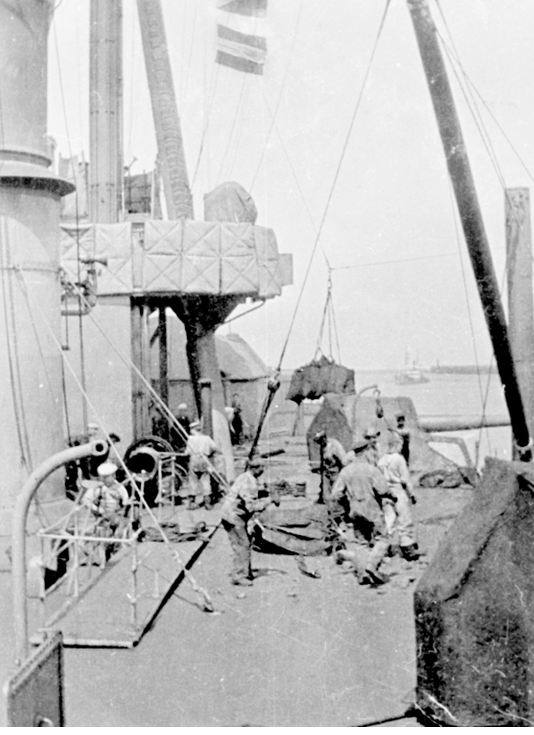
 I think I would have made the same decision. As I've said in various places on this forum, I also feel strongly that modeling is a balance between what IS right and what LOOKS right. If the viewer doesn't find the model believable, or a detail or choice is distracting from the overall presentation, it might not be the best approach even if it's technically right. For example, a model of a brand-new car or railroad locomotive might be right in presenting it as shiny and new, but in a model setting that'll probably look toy-like, and a bit of weathering to tone down the shine will probably look more right to the viewer even if it technically isn't right. So for the same reason, it's easy to justify your decision because it's too easy for the leaning stacks to LOOK wrong even if they ARE right, since most viewers have no way of knowing that they're supposed to be that way and intuition say they should be straight. And you're happy with it, which is the most important point of all.
 -
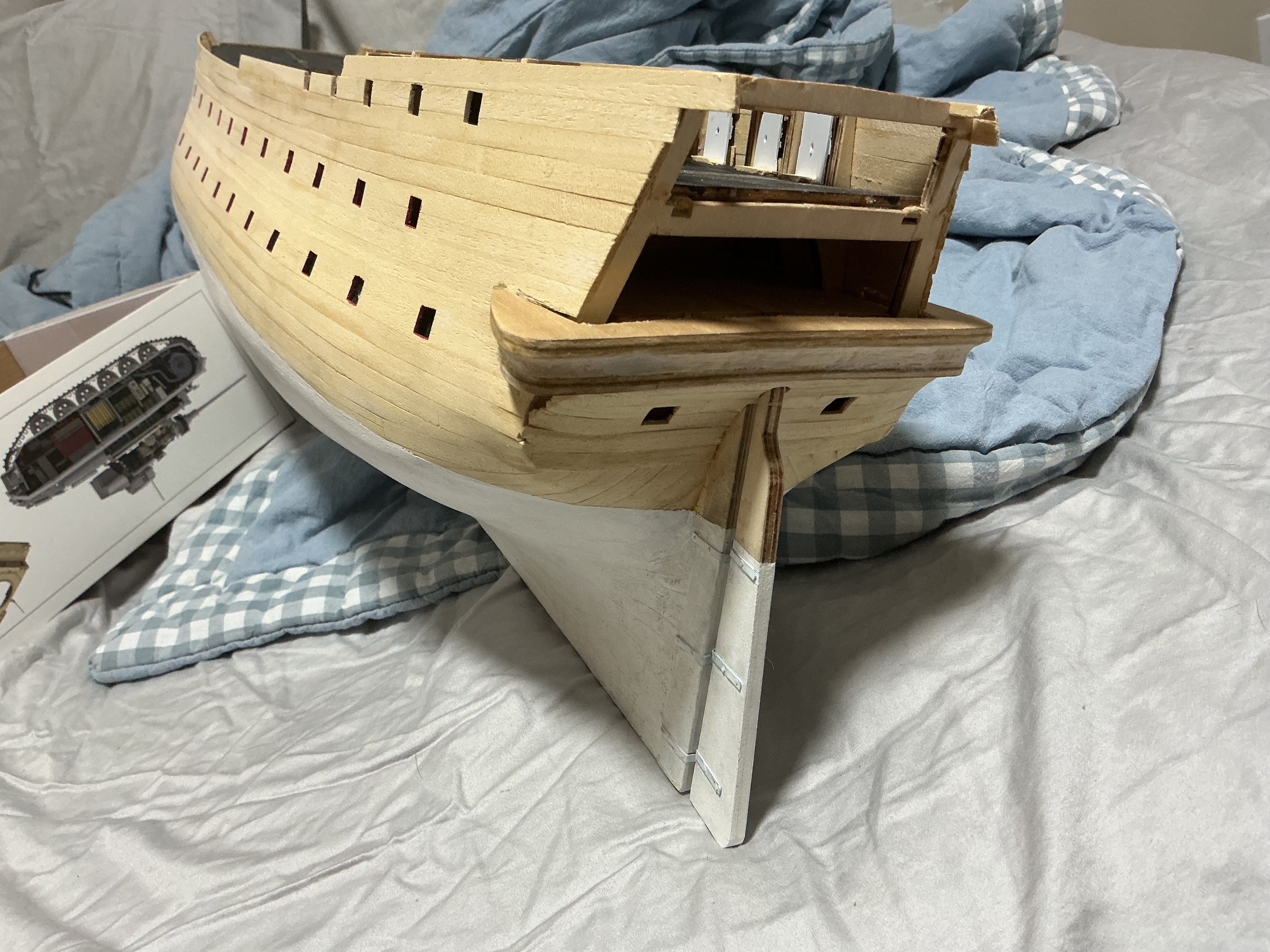
 Week 44 update: sanded and painted the lower hull, added the rudder, added 10 gunports and walls to the quarterdeck, and reprofiled the stern. Had to rip the stern gallery base out because according to the instructions the transom should be about level with the piece, which seems impossible to do without reprofiling the whole thing. Unfortunately, lots of hull planking were ripped out during the surgery despite my use of alcohol to debond the glue. On the bright side these gaps should be covered by plastic pieces and the stern gallery once work progresses. Been a while since I posted, have been working on other plastic model kits again so the pace has been rather slow. The still rather lacking instructions have not been a motivating factor for me especially when compared to plastic model kit instructions. For one, the instructions never specified on what to use to hold the rudder hinges in place. There is a stiff brass rod that fits the holes in them perfectly, so I assume that we are supposed to cut them to length and hammer the ends until they form a nail head and lock the pieces in place. Was not expecting to ever have to use a hammer on a model kit in all my life but I did. Ended up destroying much of the paint in the area so I had to repaint the section and will have to go over more coats later. Needless to say, I hope I won't end up needing this darn rod somewhere else. Also, the hinges are way too narrow and had to be bended to fit the hull. I made an error earlier with one the beams for the poopdeck which should have been glued toward the bow end of the ship, which I did not because it was a bit too short and I felt it fits the aft end much better, turned out that was a mistake because two of these walls had a cutout meant for the beam to rest on and help hold the walls up. I didn't want to risk damaging the ship again by ripping more stuff out so I ended up having to jerry rig a solution by extending the walls to reach the now farther beams. Might be another couple months but I will update again when I have some more progress to show.

-
.thumb.jpeg.ffac2f8a24d212961a83eab4efb06a6c.jpeg) Seems like an appropriate choice for a Bounty launch.
Seems like an appropriate choice for a Bounty launch. -
 Thank you for the kind comment, mcb.
 -

USS Constitution by mtbediz - 1:76
GGibson replied to mtbediz's topic in - Build logs for subjects built 1751 - 1800
What a great solution, Mustafa! It looks great! Another tidbit I need to remember. 🏆 And, of course, Jon has all of the historical pictures! 👍🏆 Wow! I knew this end of the bowsprit around the martingale was busy but wasn't fully aware of all of the features. Anxious to see how each of you complete this! -
 Yup, well said Gents. The Birchwood Casey stuff seems to be a bit of "Hit and Miss" no matter how many times I review videos etc. I attempted to get my hands on Liver of Sulphur, but it seems like "Aptocaines" are not what they used to be.... 🙂 I'm o.k. with Chemical Blackening on things like Eyebolts/Rings and Chains and so long as they are not handled too much the Patina is acceptable. One really bad experience that I had was attempting to Blacken Chainplates with the Deadeye in situ. The Deadeyes assumed a greyish tint.. I guess this would be different if the wood had been sealed prior. Cheers....HOF. Matt Black paint is my go to for the Chainplates.
 -
 Congratulations again. As usual your work captures the mood or 'spirit' of the subject. Thanks for posting. mcb
- 386 replies
-
- 1
-
-
- Billy
- sternwheeler
- (and 1 more)
-
Very interesting! Thanks for sharing! Being used as a base, will you stain it, then? How does Ulu take a stain?
-
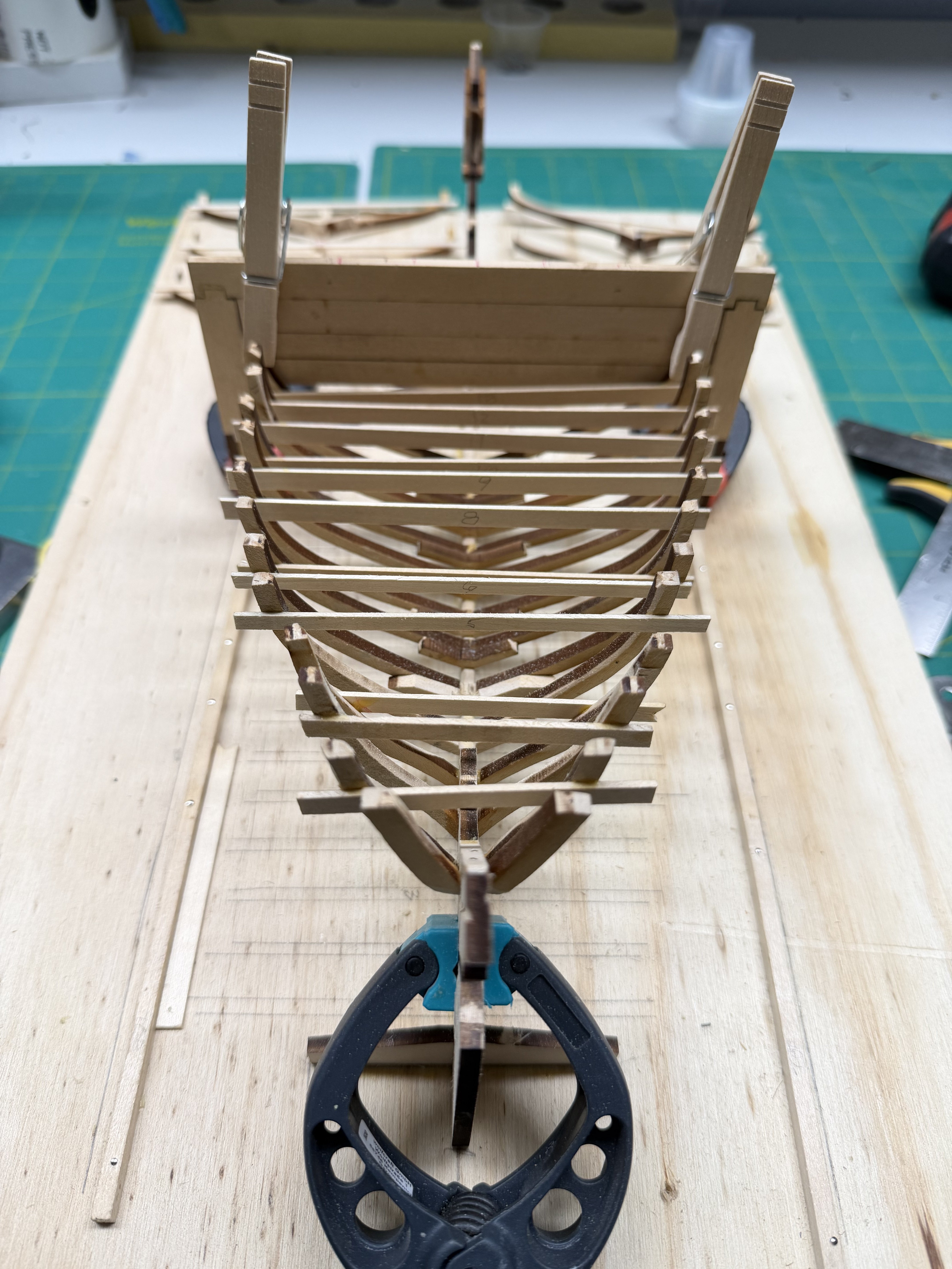
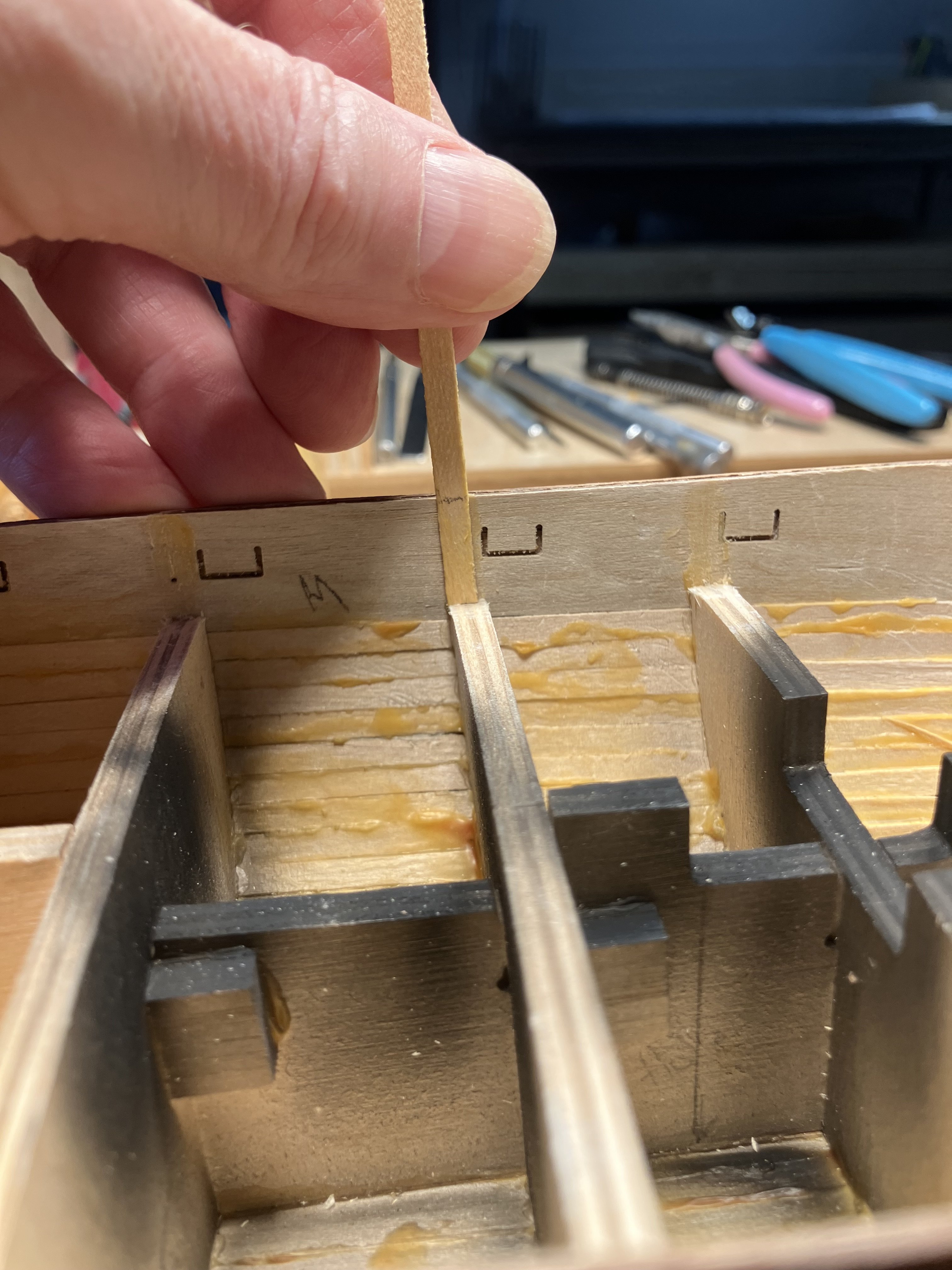
 The first 13 frames are installed. The next six are assembled and waiting their turn. You can see in the photo that I added another "layer" of material to the cross bar as the tops of the frames were getting close to the bottom of the original (as modified). Hard to get a grip with the clothespin without the frame wanting to twist under the cross bar. I really think the kit designers could have picked a better place to put the "holding tabs' on the frame pieces. As it is the parts of the frames that join together (and generally a very small area to boot) contain one of the two areas where the laser does not cut all the way through. Don't ask me how I know but that makes these areas subject to some "clean up" which may further distort or remove material that is badly needed to keep the two frame pieces together.
-
 From time to time I have been posting info on wood found in Hawaii. Today it is Breadfruit, or as it is called in Hawaiian "Ulu". As you can see Ulu is a wood that is attractive but has a rather coarse grain. The wood machines well and can be carved with hand tools. The Hawaiians primary use of the breadfruit is as a food source. The trees are not harvested for timber unless the tree has to be removed for some reason. As a result the wood is only available in small amounts when it is available. Because of the pronounced grain it isn't likely to have much use in model building. This piece was given to me by a friend who is a professional wood turner. I plan on using it as a base to mount a model of the Bounty Launch.
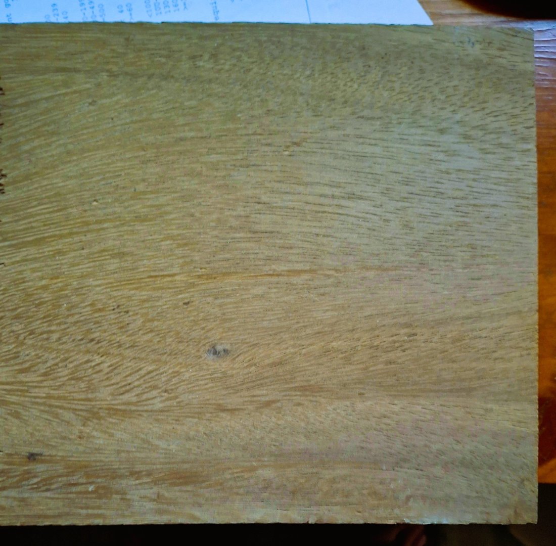
- Yesterday
-
 I would strongly recommend that anyone that builds the AVS to follow CISCO's method of laying out the second level of planking of the hull. I just started by following the Luck Street practicum, I could have avoided many errors if I would have gone to the detail that CISCO did.
 -
 Trevor, I hadn't thought about the need for the sheave to be the diameter of the mast. I'll do the calculation and see what I come up with for the second hole. The only wooden boat I've ever sailed (my in-laws' Wianno Senior) was gaff rigged, and had blocks for the main halyard. It's frustrates my doctor OCD traits that the provided instructions are so imprecise, and that they don't correct them. Maybe Model Ship World should start a forum listing known mistakes in instruction manuals. Tom
 -
 What a great 'little fleet' Keith. Billy is a great result of your persistence in trying to get it right; how many attempts at the lettering? The result, as Glen has said, is a unique little model. Congratulations Pat
- 386 replies
-
- 2
-
-
-
- Billy
- sternwheeler
- (and 1 more)
-
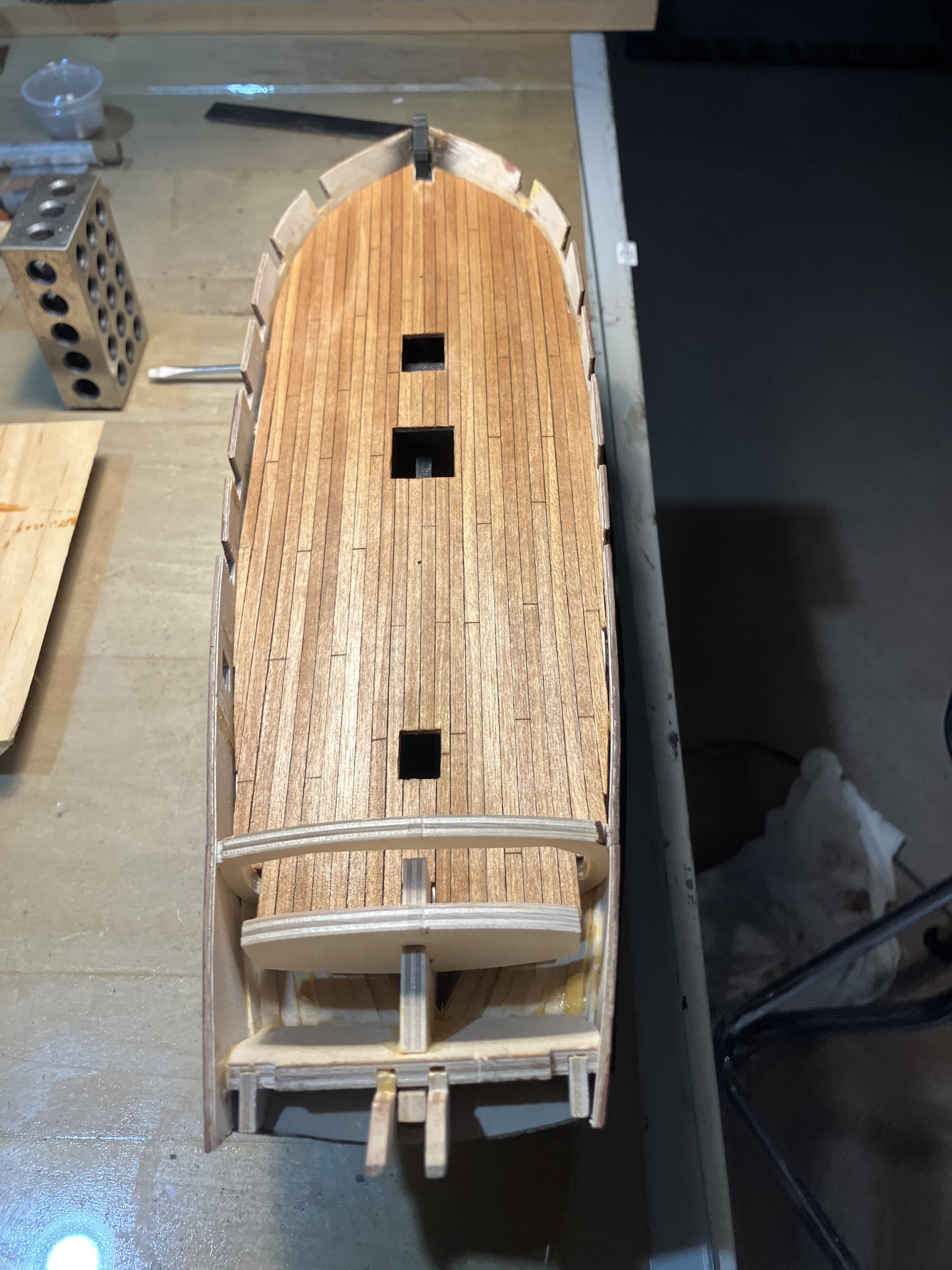
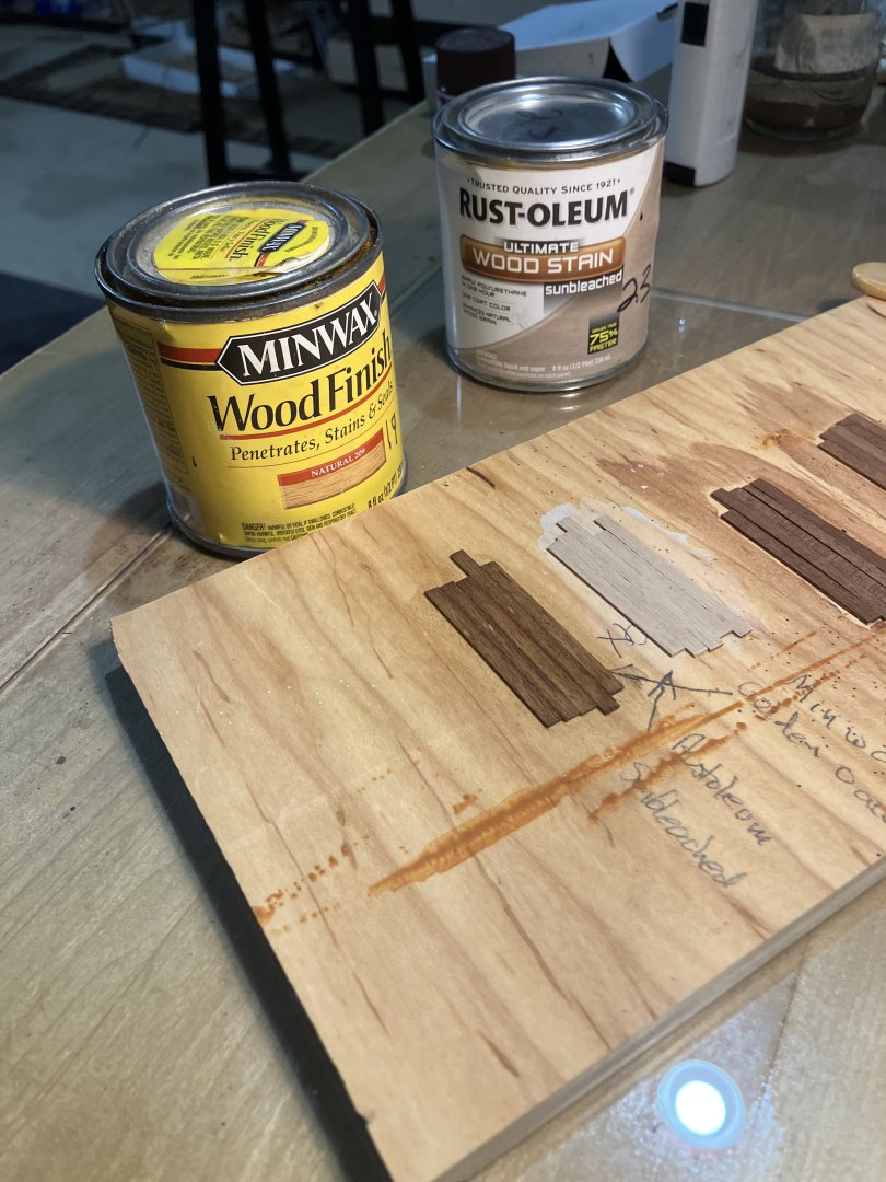
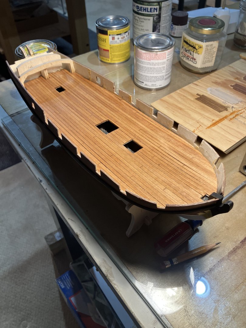
 Planking and Finishing the Gun Deck Planking the deck was straight forward. In the past I would cut the stripwood into scale lengths, this time I followed the Tip in the instructions and used a single strip and scored the butt joints. The work went much faster. Next I made up some board samples and tried Rustoleum Sunbleach and Minwax Golden Oak. In the end decided on Minwax Natural. Nice results….
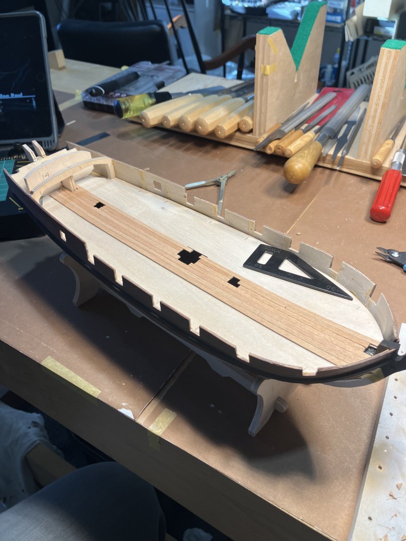

-
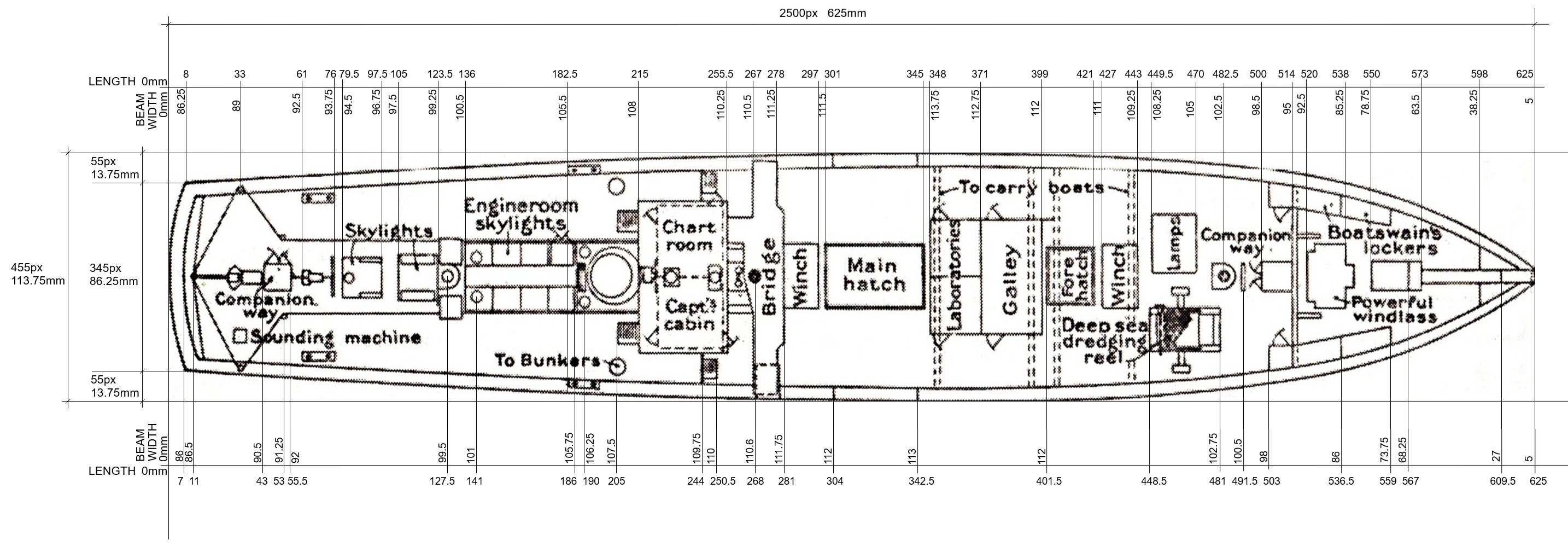
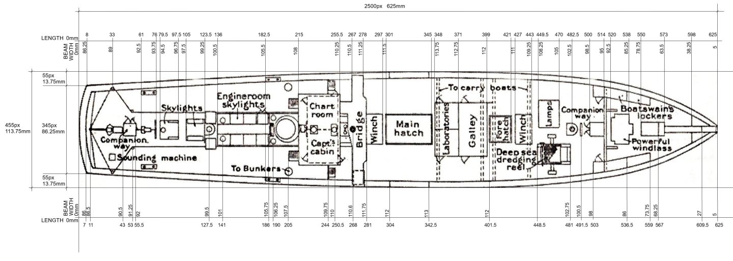
DECK MEASUREMENTS For a 1mm = 4px image. . . https://drive.google.com/file/d/1OOwLHzFPkg6h4SOSlOrZRsu-9JZbc1xb/view?usp=sharing
-
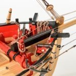
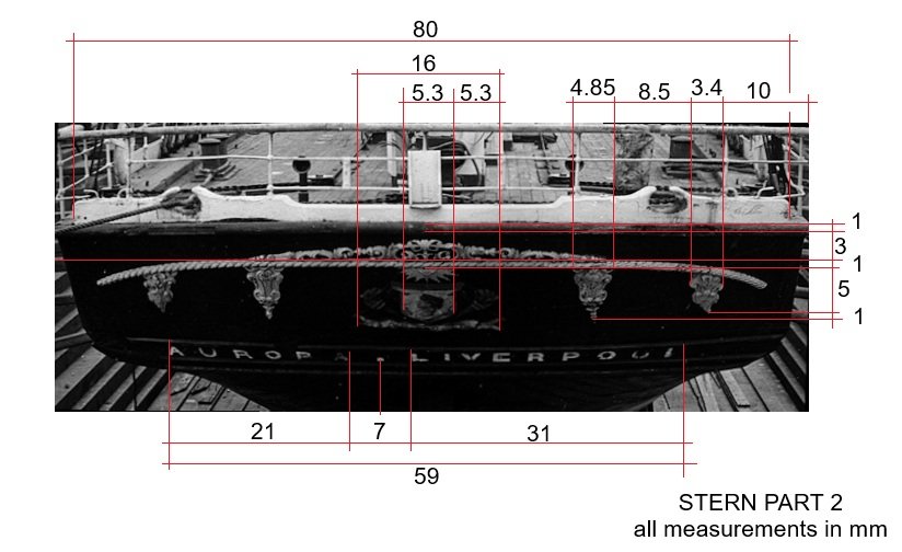
STERN PART 2 The ornament is slightly off-centre, but not due to optical aberration.
-
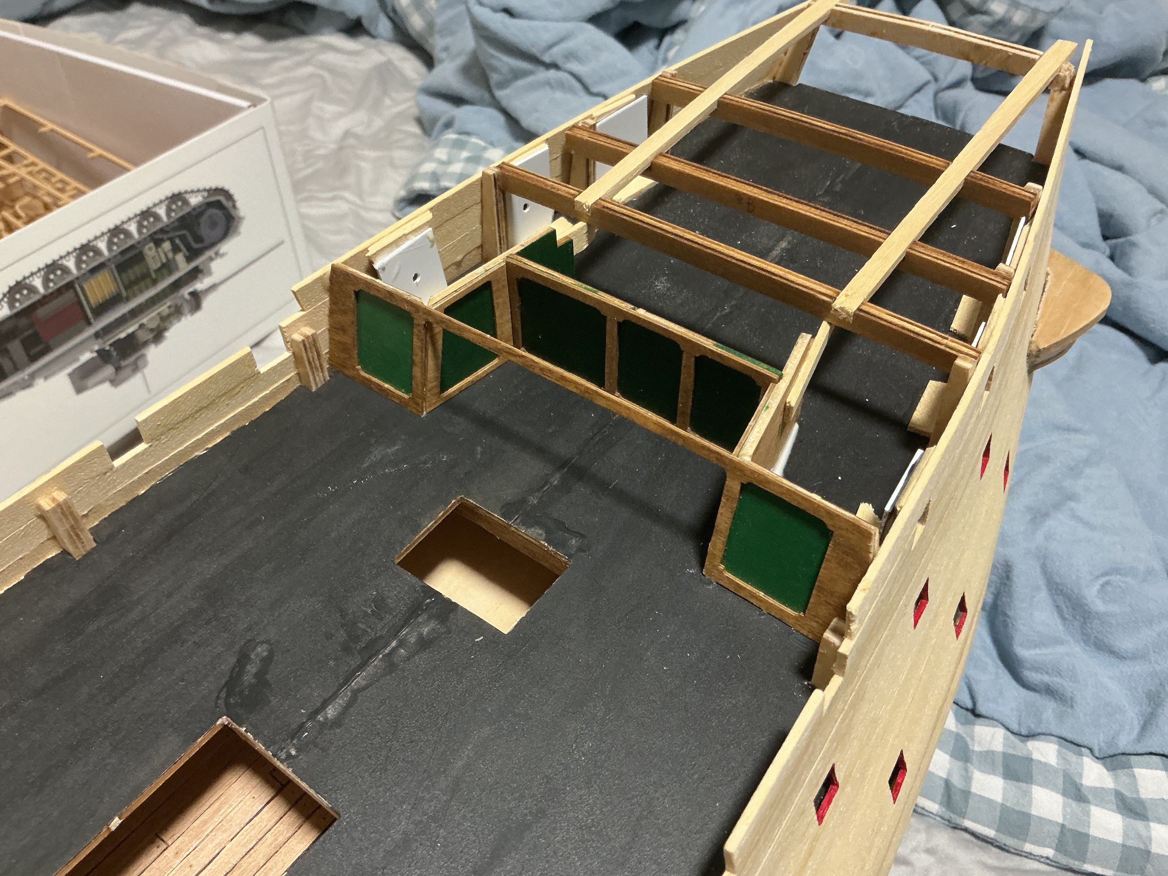
Installing the Gun Deck Before installing make sure the height from the top of the frames outboard to the top of the bulwark are consistent. I used a “story board”, a plank with a pencil line where the line is the distance from the highest frame to the top of the bulwark. Make up 2 boards one for forward of the Captains cabin, one for aft. In my case there were several frames that needed shims at the outboard end because I was too aggressive when cutting the frame stubs. Next the deck was installed with Titebond across the frame tops, and CA at the outboard ends.