
James H
-
Posts
5,616 -
Joined
-
Last visited
Content Type
Profiles
Forums
Gallery
Events
Posts posted by James H
-
-
-
-
-
1 hour ago, Phalpenny said:
Great work James. Your posts have been very helpful for me with my build. I wondered how you secured the spritsail boom to the bowsprit. Did you glue it or attach it with thread? The instructions suggest the latter method but I can't see any thread in your photos. I'm thinking that gluing it might be easier and more secure? Thanks!
You can use thread for lashing, but I pinned in position first with a small length of 1mm brass wire.
-
2 hours ago, Malcolm Greig said:
Thanks Glenn for doing the heavy lifting with this early build. I am sure many members will benefit and successfully negotiate the tricky stern area because of your build log. I'll sure be careful when I get the Sphinx off the shelf.
I'm sure someone already did the heavy lifting before the kit was released 😉😝
I did try to make you a manual that showed everything in the smallest detail.
-
-
-
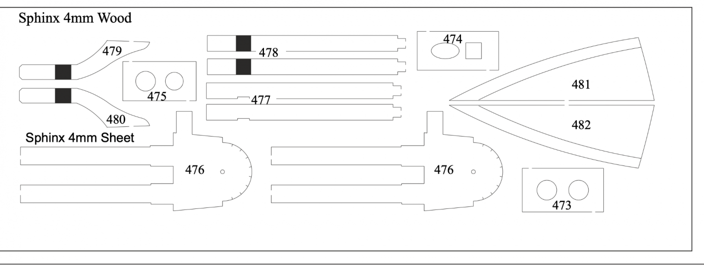
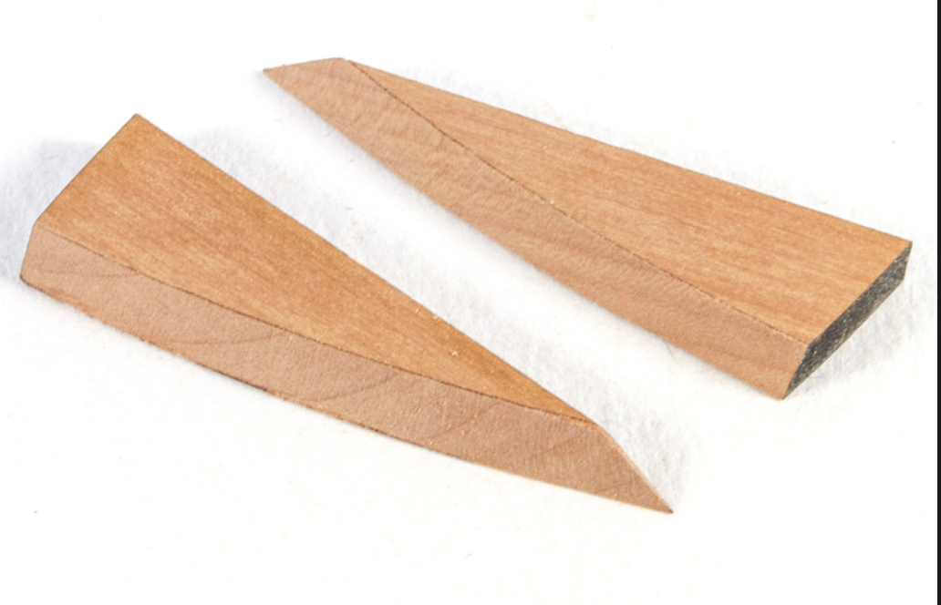
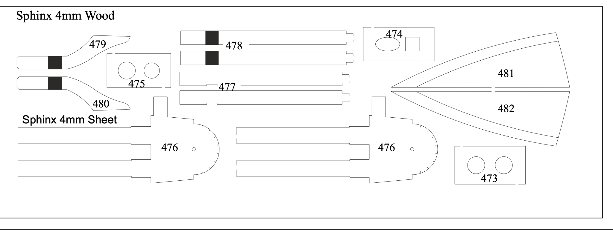
Glenn, that roof looks like MDF. That is supposed to be pear. Have you used the right parts? The pear parts are engraved with the bevel shape for roof. If didn't need to be manually marked.
If you still have the pear, remove material from the rear edge so the curve matches your gallery, then bevel to the curve to create the inward sloping roof.
Parts 481 and 482:
- mtaylor, BobG and Haliburton
-
 3
3
-
36 minutes ago, glennard2523 said:
Thanks James
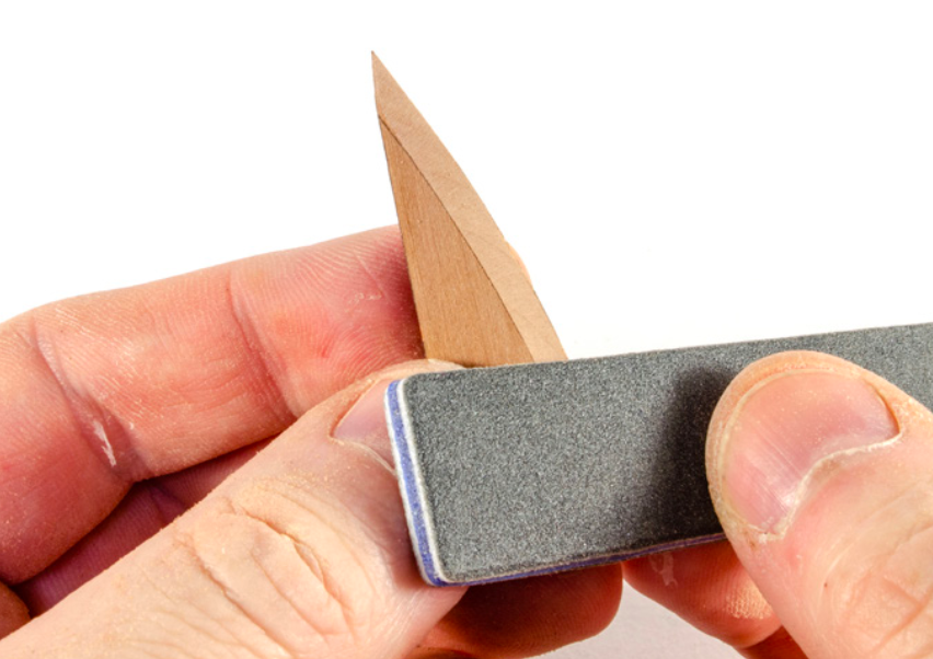
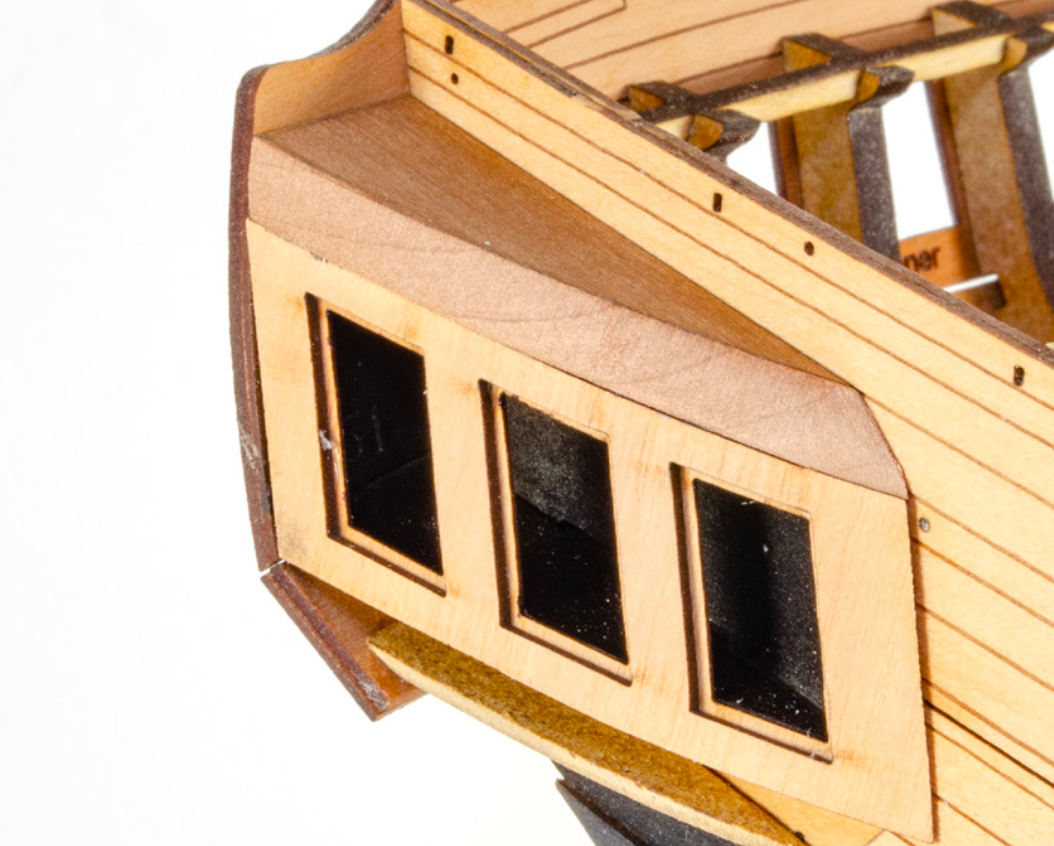
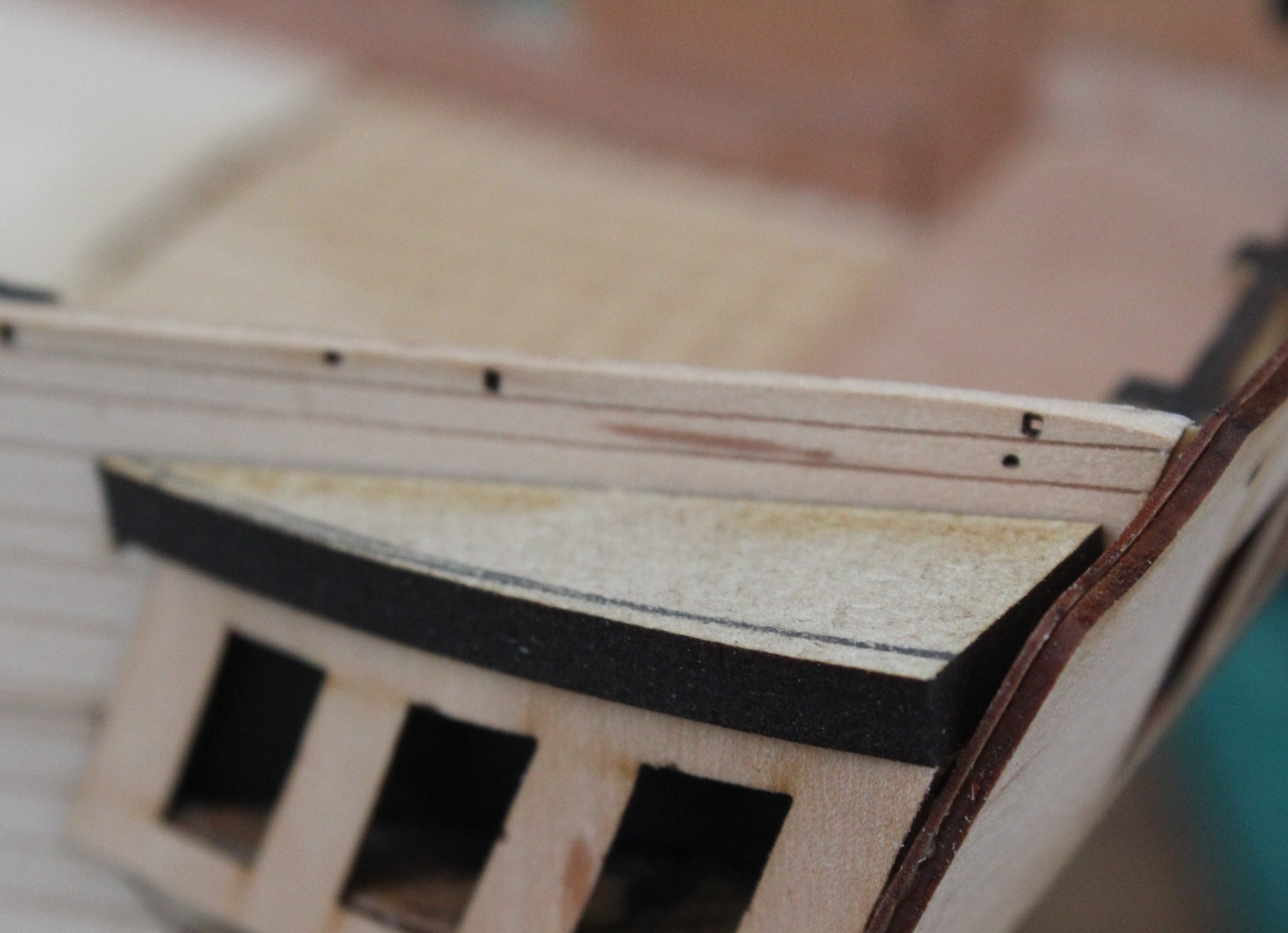
The top roof pattern leading edge was shaped before I glued in place. I made the mistake of shaping the leading edge before the outer window pattern which meant the window pattern was sitting proud. of the top pattern.
This picture shows the marking I made before I sanded the bevel.

I can see you cut it down to match the flow of the gallery, but where the gallery reaches roof height, the roof is bevelled inwards at an angle. For example, if you'd removed the excess material from the straight edge, the curved shape would have matched your gallery curve, the part would then have been bevelled so the roof leaned inwards from the gallery. Look at the shape of my roof angle at the front. It's not vertical. That shows the bevel where the roof leans inwards.
- BobG, Haliburton and mtaylor
-
3
-
Hi Glenn,
You needed to shape/bevel those roof sections before fitting, to allow the upper decorative trim to fit, plus you have that PE shingle to fit too. Test the fit of those parts before proceeding further.
- BobG, mtaylor, Haliburton and 1 other
-
4
-
-
Ok, been taking a good look through this and that problem you're encountering.
When I built my prototype, I originally set the stern counter too low, meaning the stern fascia was too low to the bulwarks. You'll see my correction in plan where I said about elevating 2mm to the lower side of slot. That measurement is correct. Take a look at this picture from my own build:
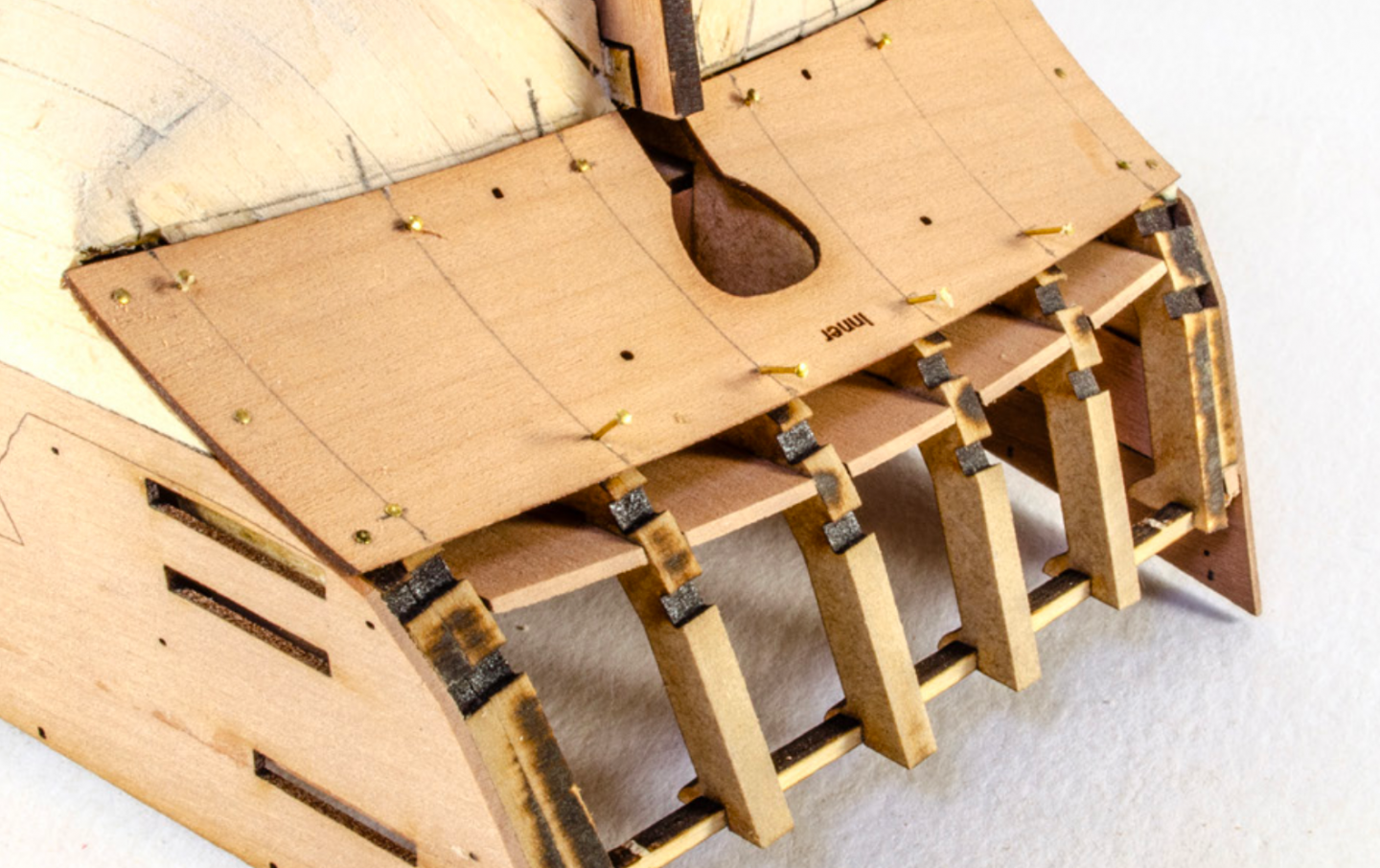
Where I made my mistake was not making the top corner of the counter sit at the point on the side pattern where the angle changes....adjacent to the bottom of that slot you see nearest to us in the pic. It's literally only 2mm. Elevating to there will fix the issue......but.
...in your pic, the counter isn't in the correct position with its angle and doesnt sit in relation to the end of the side patterns. You had to put a filler piece in here to compensate, dropping that lower edge to create the gap you have. If everything isn't looked at stages ahead to check for any effect of impact, then you can't retroactively push yourself to the point where everything will align.
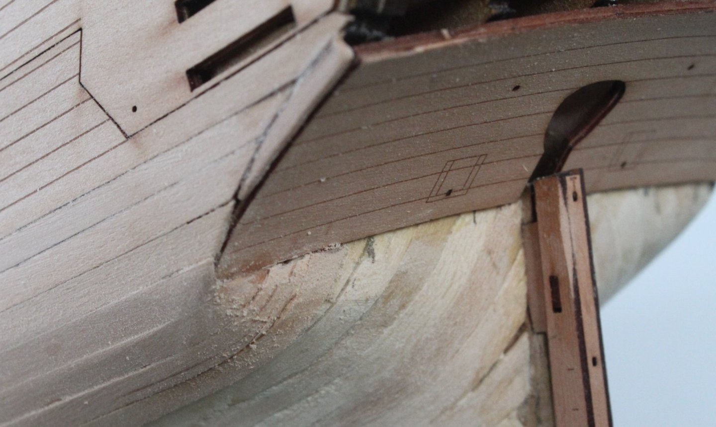
To be honest, I'd rip that stern counter off and start that area again so the part is sitting properly into that curve.
I can't see any way around the other alignment problems you'll face further down the line with rails etc.
- chris watton, mtaylor, BobG and 2 others
-
5
-
-
-
2 hours ago, Jasseji said:
@James H could you confirm the measurements which Christ posted on the box ? I will need to get an Acrylic enclosure before i even dream of starting on the fittings and Masting so the Cat is kept away from the oh soooo tempting thin pieces
Yes, give or take a couple of millimetres, by Sphinx is around the stated size.
-
-
-
-
-
2 hours ago, Jasseji said:
it wont be visible and i myself dint have any issues gluing to charred edges but in case of this model, removal off all char is an indication when the frames have been faired enough (at least on the bulwarks inner and outer)
You got it. All char removal is a good indicator that all is faired to the same level for inner bulwarks. I just used a piece of 110 grit paper, doubled over for stiffness but allowing to form into bulwark side shape.
- BobG, Blue Ensign and mtaylor
-
3
-
-
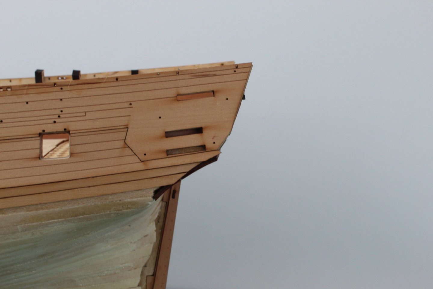
Make sure that stern counter upper edge is roughly along the bottom edge of the stern timber slots.
You can see the amendment in the manual. If you set it too low, the rails around the stern won't match those on the galleries and the stern fascia will be too low with the top of the bulwarks towards the top of the fascia.
-
2 hours ago, chris godson said:
Hi James, I know it's a long shot but any news on the Amati HMS Victory kit?
Just sit tight and follow this topic.
When there's any movement, this is where it will be posted.
- AJClark, mtaylor, hollowneck and 2 others
-
5
-
53 minutes ago, BobG said:
Having these beveling lined included is so helpful as it takes away a lot of the uncertainty of roughly beveling the bulkheads and the bearding line off the model before the final fairing. Is there any particular reason that these lines are not included in the larger Vanguard models like the Flirt and the Sphinx?
Also, what are the overall dimensions of these wonderful models?
I think with Sphinx taking a full day to produce, adding more to it wouldn't be beneficial (especially in cost to the customer), plus it's sort of reckoned that if you are building at Sphinx level, that you can work out any rough bevelling quite easily. The manual does show that bevelling, so the builder isn't really in the dark, so to speak.
Ok, dimensions:
Erycina, with masts and bowsprit is 525mm long x 379mm high
Nisha, with masts etc. is 387mm long x 311mm high


HMS Sphinx 1775 by Blue Ensign - FINISHED - Vanguard Models - 1:64 scale
in - Kit build logs for subjects built from 1751 - 1800
Posted
@Blue Ensign That looks absolutely spot on.