


thibaultron
-
Posts
2,876 -
Joined
-
Last visited
Content Type
Profiles
Forums
Gallery
Events
Posts posted by thibaultron
-
-
I'll be following your build! I have this kit on order, thought I may not build the full mast, due to the height.
-
Welcome to wooden ship modeling! You've made a great start.
- druxey and Ryland Craze
-
 2
2
-
-
-
-
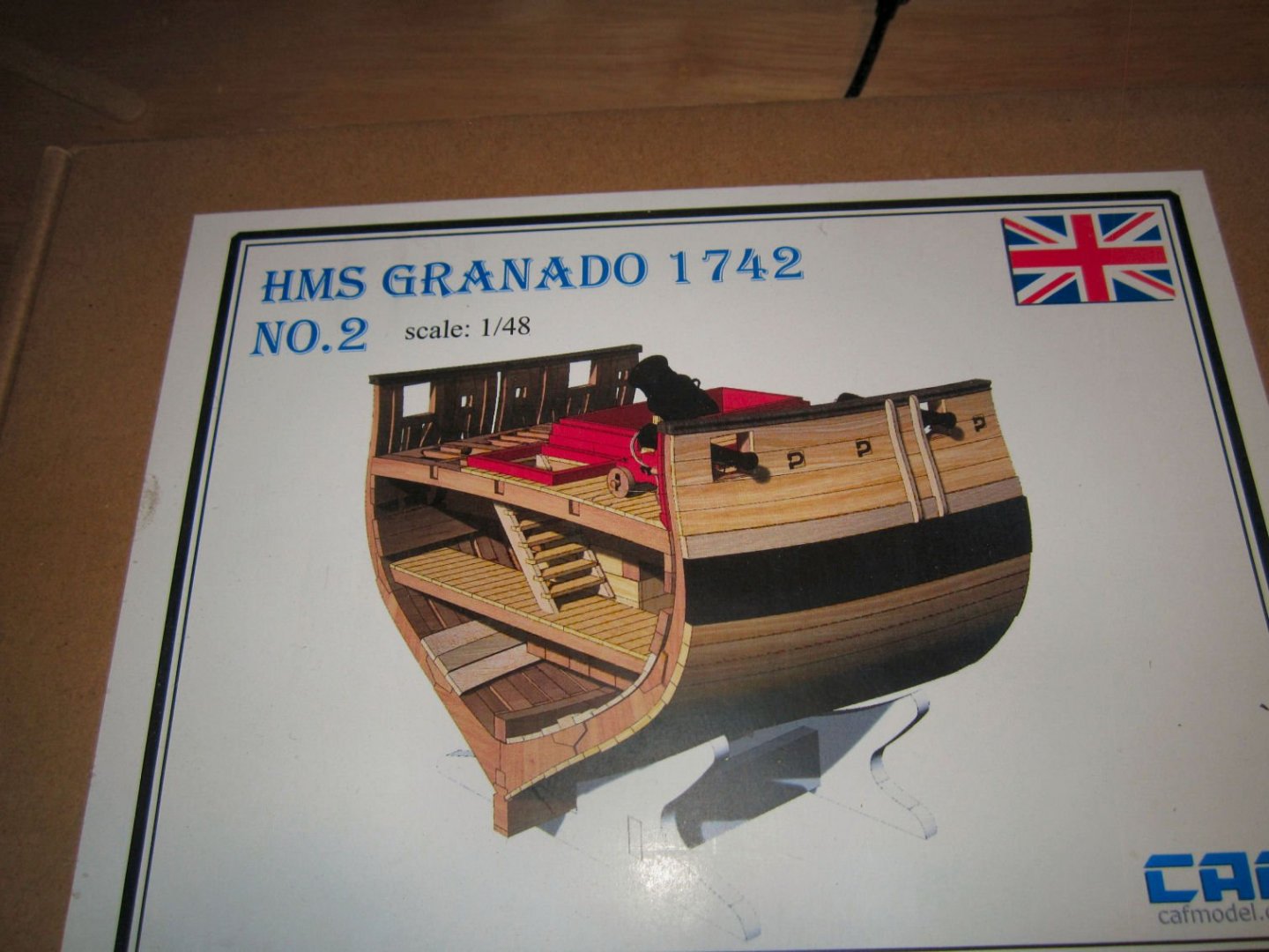
Part 001
I’m starting my build log of the CAF Models HMS Granado Cross-section in 1/48th scale (https://cafmodel.com/). This kit is a Plank On Frame with one side planked, and the other unplanked, to show all the frame/rib detail. CAF has a slightly different approach to the traditional (at least modern tradition) laser cut parts. Instead CAF CNC Mills the major components, allowing for better preshaping of the parts, for the modeler. Their site has more pictures of the completed model.
The HMS Granado was a Bomb Vessel. Instead of a broadside of cannons, she was build with just a few defensive cannons and two large bore mortars set in wells on the deck. Regular cannon were setup for ship to ship engagements, and could not be elevated to any great degree. Thus ships of the line could not readily reduce a fortification, unless it was set at close to sea level, and even then they could mostly just attack the walls of the fort.
The mortars on a bomb vessel however were designed to fire at high angles, allowing it to fire over the walls, into the interior of the fort itself. They were also of a much larger caliber than even a large broadside cannon. The mortar shells also had explosive charges to increase the damage.
The bomb vessels were generally moored in place, out of the range of the fort, during action with anchor lines at the bow and stern. This allowed the ship to be turned to further zero in the targeting aim, and insured that once the range and target were attained, repeated fire would land in the same spot, rather than having to resight for every shot. The ship was defended from ships of the enemy fleet, by regular ships from her navy.
To allow for a clearer field of fire the ships generally had two rather than the typical three masts, that a warship this size would carry.
This model is of the larger of the two mortars, along with the cover for the well, used during sailing, to prevent water from filling the well from wave and rain. The cross-section includes the large deck support beams, and the racks the shot was stored on.
Here is a photo showing a drawing of the completed model.
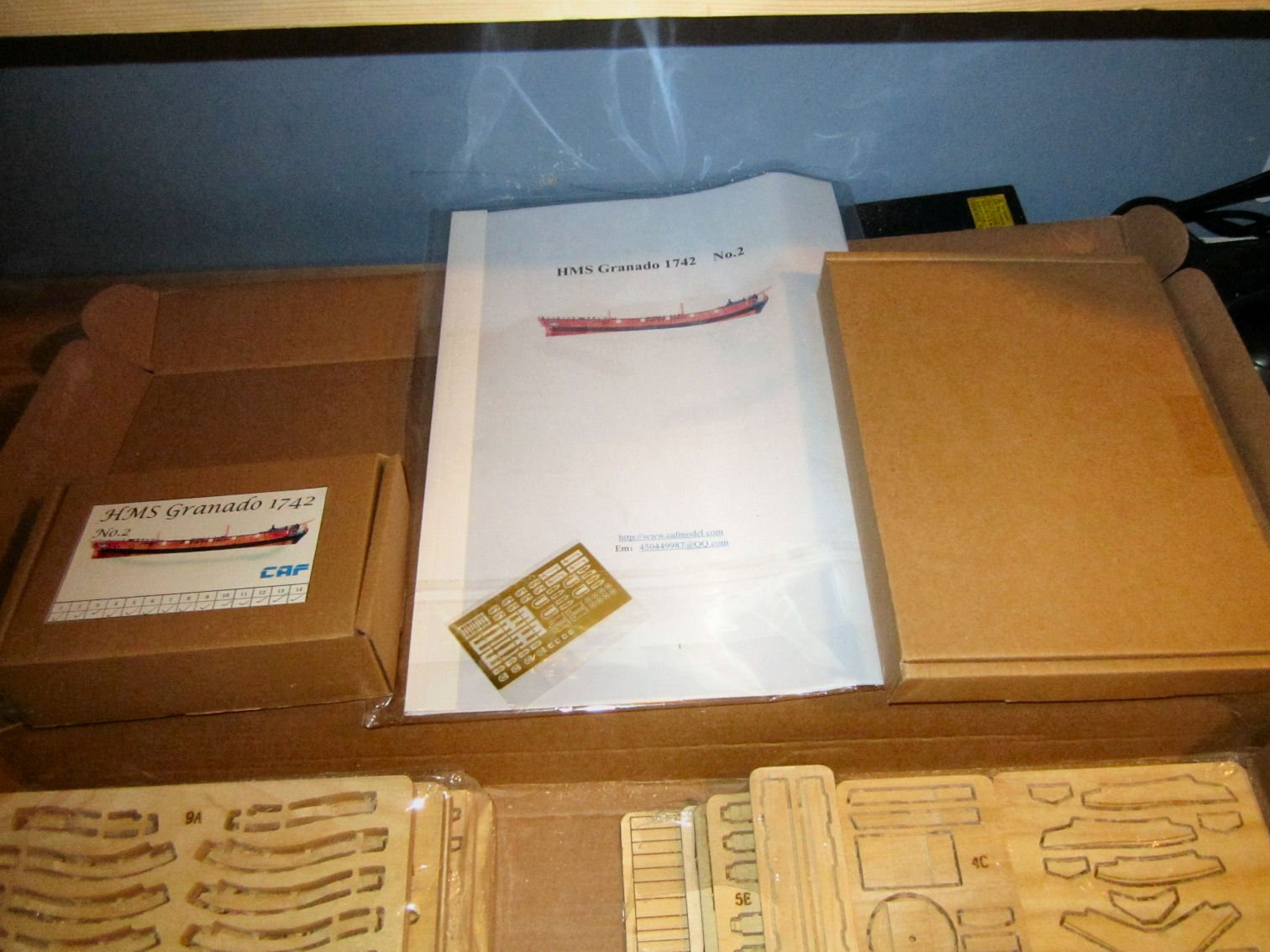
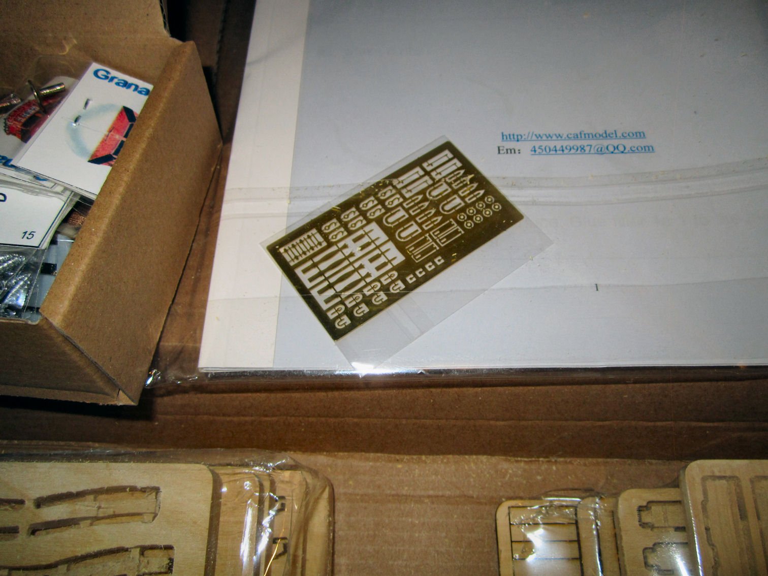
The large box is fully packed with modeling goodies!


One box contains all the hardware for the model, as well as hardware for the unique acrylic building frame. You build a box with supports for the frames and then assemble the model in this box, once all the individual frames have been assembled.
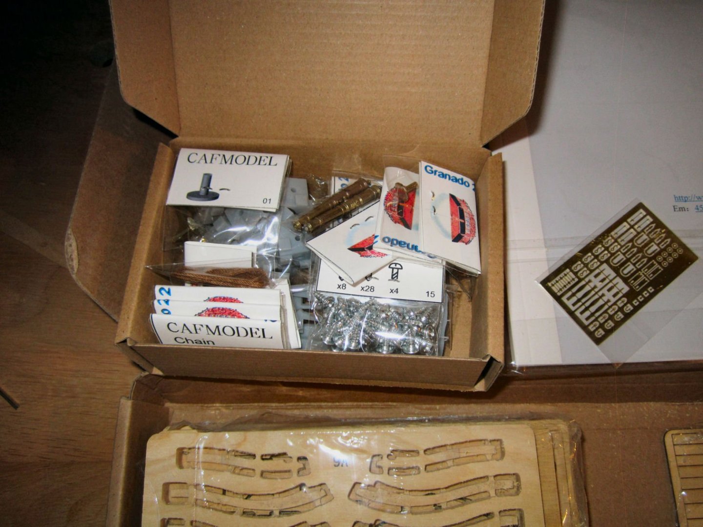
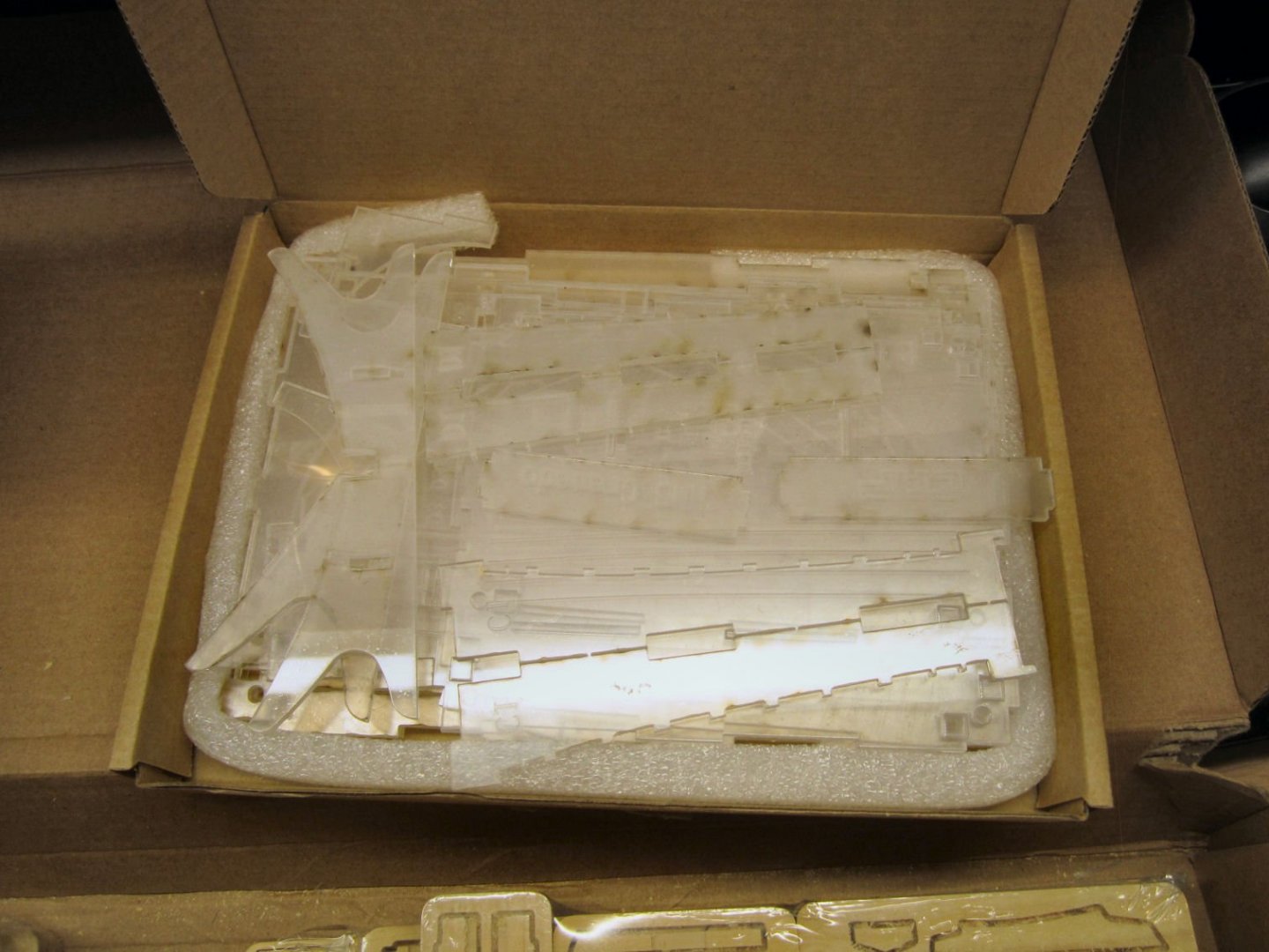
The other box has all the acrylic pieces for the frame box.
There is also a small sheet of photo-etched details.

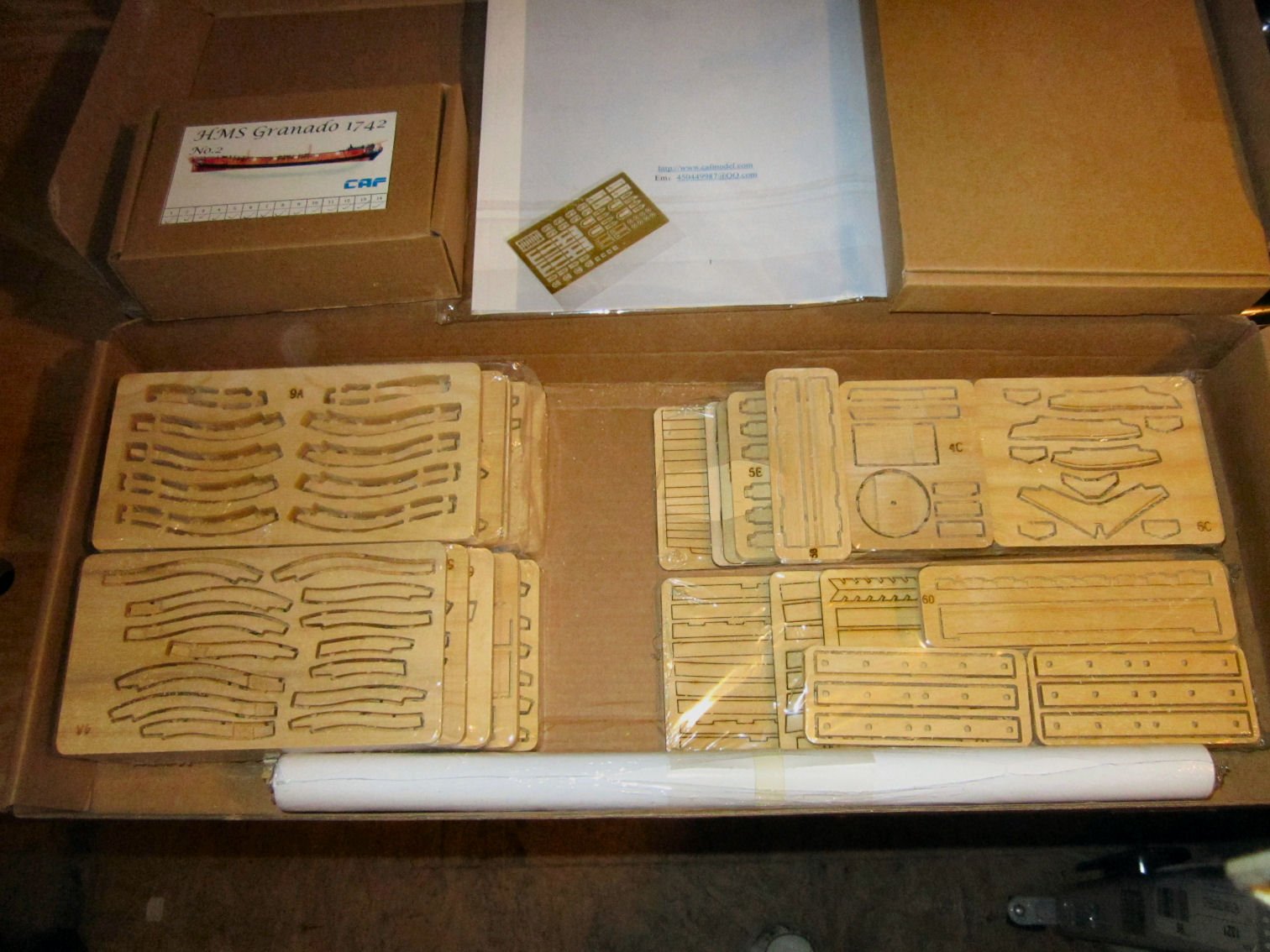
Included is a set of plans.

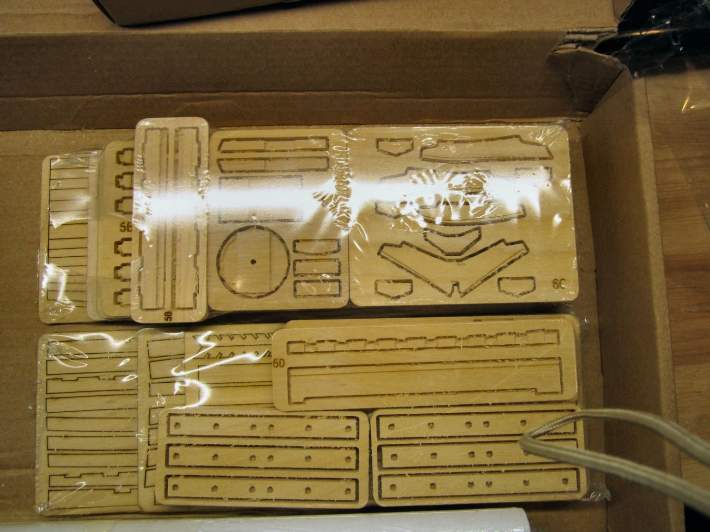
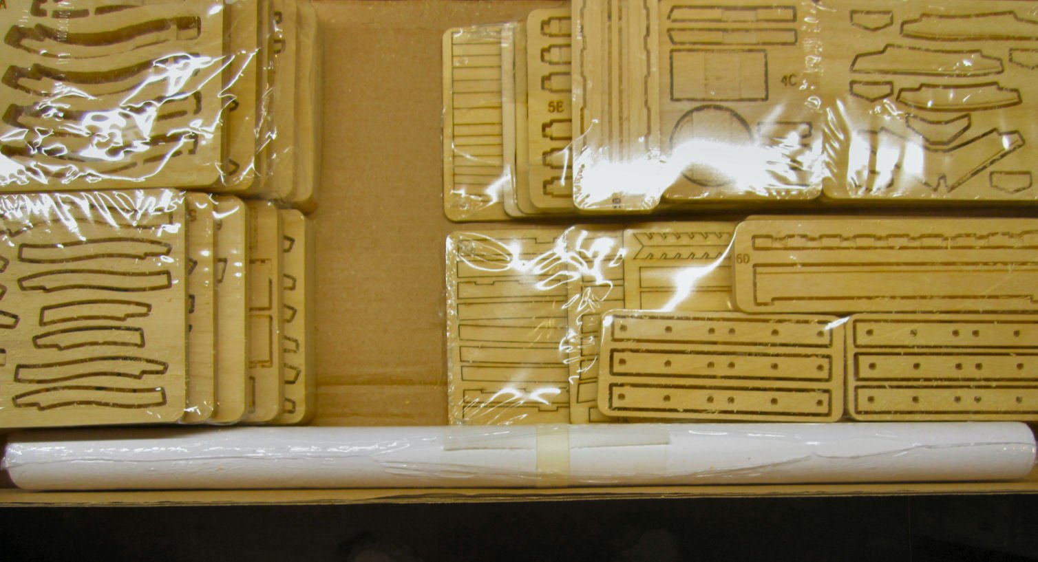
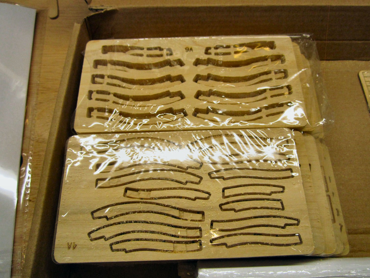
These photos show the CNC milled wood parts. They are staying in the shrink wrap, and I will open them as needed during the construction. If you look closely you can see that some of the pieces have been milled on all sides to the correct shape. There will, of course, be more shaping on most of them, but a lot less than if you started with parts that were 2D laser cut on just two sides. Some of the flat parts are laser cut.
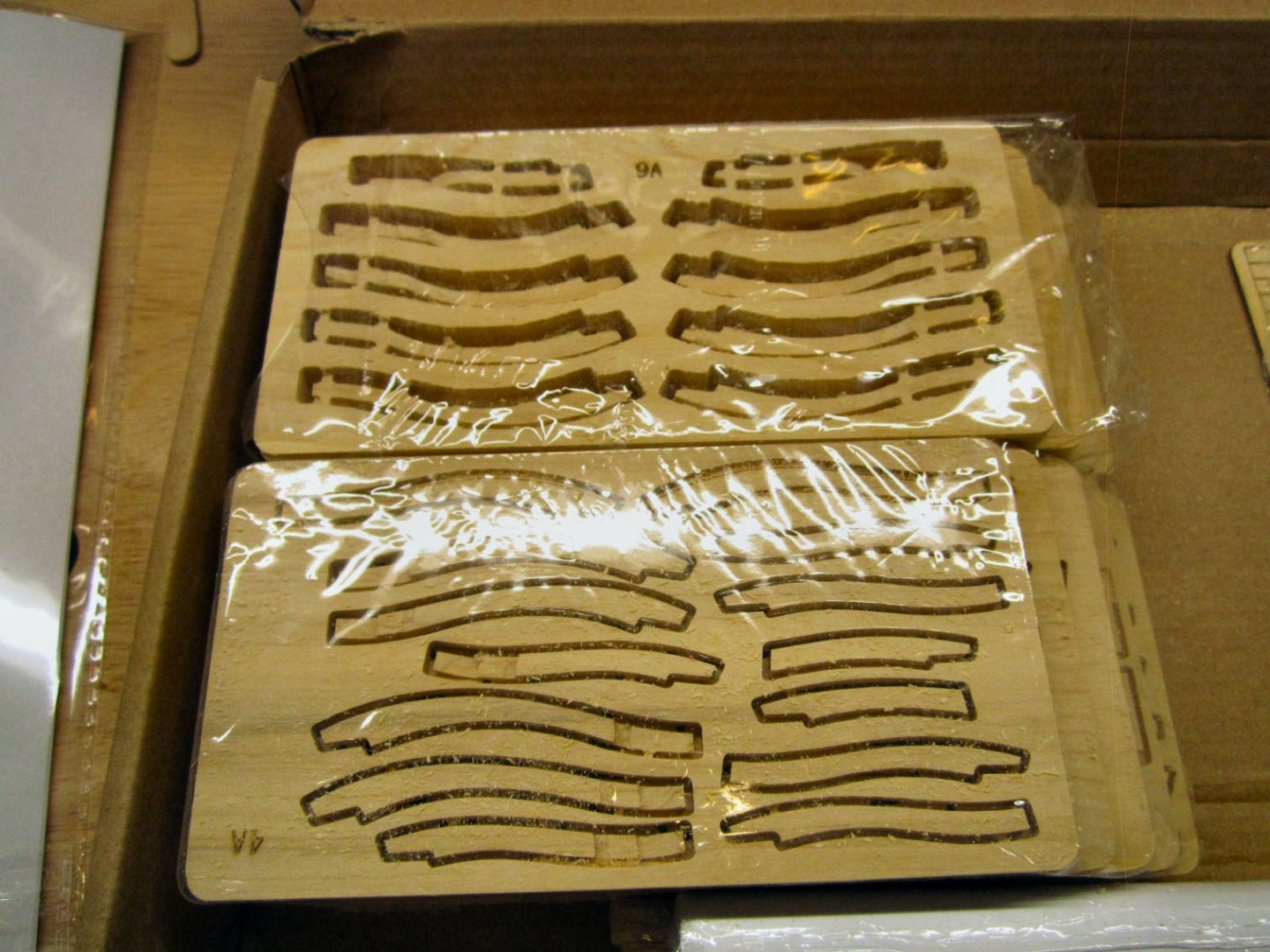
The loop hanging down in this shot, is my camera strap, opps.
The instruction book is a well detailed, illustrated step by step guide. It comes in a semi-bound clear binder. I proceeded to unbind it, by peeling off the cover, scraping the glue along the spine, and removing the staples. I’ll scan the whole book, so that I can print out each page, if any should get damaged during the build. I have more than once spilled glue or paint while building a model.
I will also scan in the plans, for my own use only, so that I can print sections of the plans that you build various assemblies on top of. The frames, for example, are built on top of the plans.
-
-
That's like the Lowes "Craftsman Tools". They are not made by the same company that the Sears Craftsman tools were made by. Lowes bought the name and logo from Sears, but Stanley makes the tools. Sears still sells them, also, but reserved the right to continue to have their original manufacturer produce them, for I believe 10 years.
-
Curses!! Another hit to my wallet! Thanks for the reference, I ordered one from Amazon.
-
I used the information in the Hand Reef and Steer book to develop a rigging plan for my Maryland Terrapin Smack. Chappells plans do not give details of the masts, or rigging, though they do show the spars. Anyway this book cleared up some of the mast rigging details I needed.
-
-
-
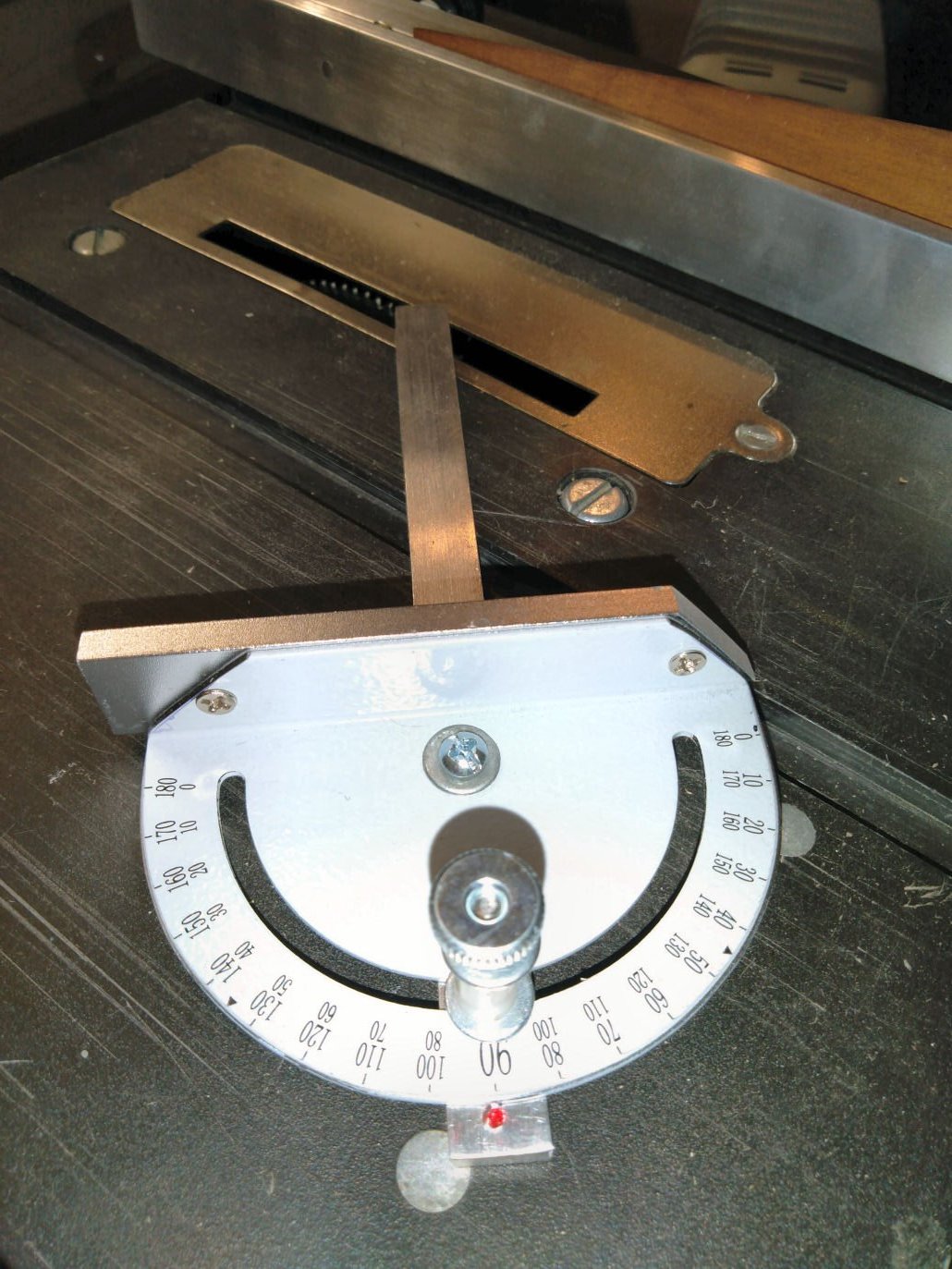
Part 009
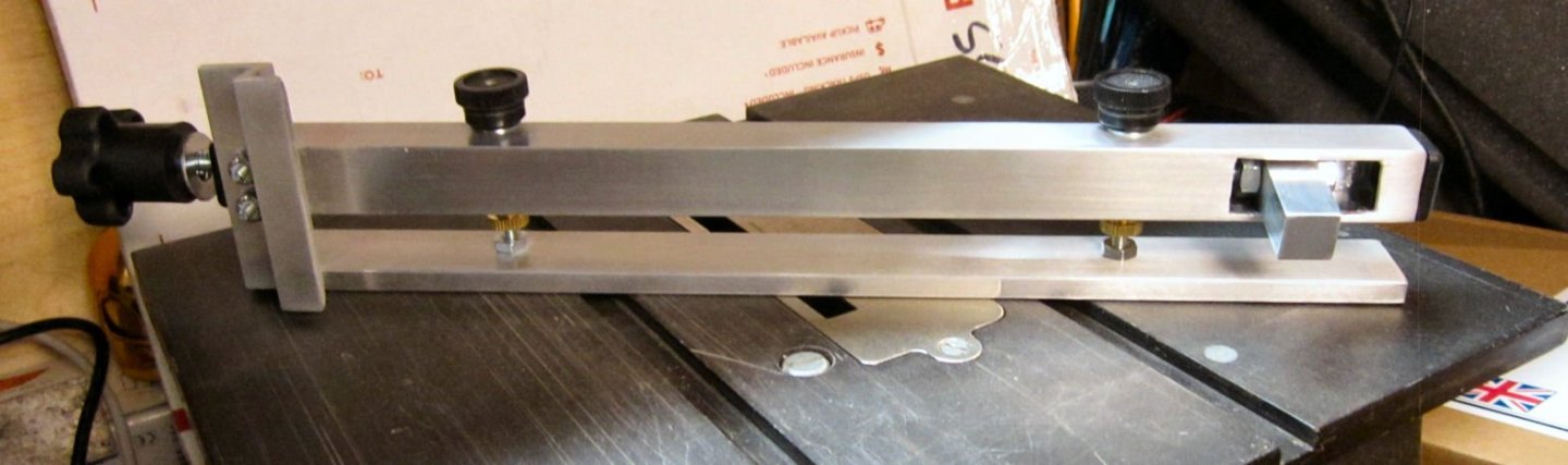
Yesterday the new Miter Gauge I bought from the same person I purchased the backplate and rip fence from arrived. It is a well made all aluminum assembly with nice large angle markings on it. It fit well in the table slot, with only a little slop, much less than the factory one. It also has a larger miter assembly, with one side angled at 45 degrees. The gauge has a nice thick blade screwed onto the protractor, giving a good surface to hold your work piece to. The only down side I see to it is that the position marker on the slide is a dot, rather than a line, making it harder to set the correct angle. The locking screw is well made and provides a strong grip when tightened.
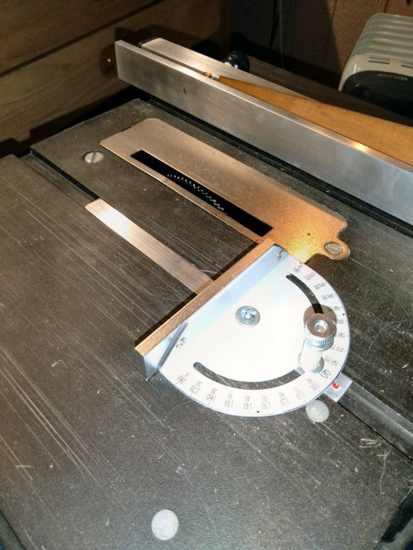
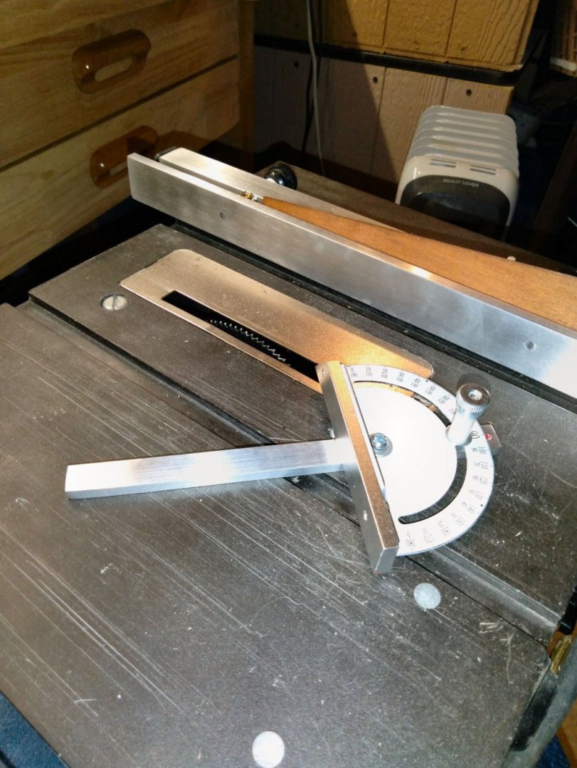
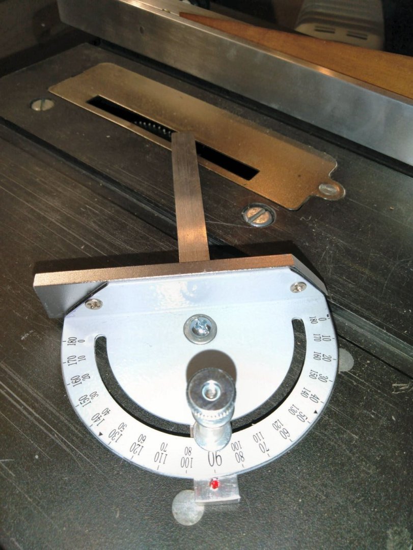
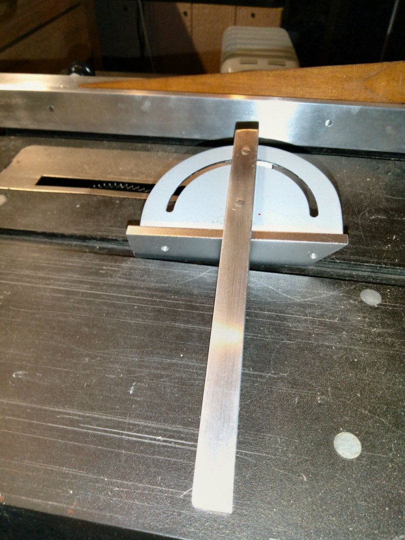
I tried cutting some old ¾” X ¾” hard pine strips on it for a project. It did stall a couple times, when I tried to feed it through too quickly, but I was using a 100 tooth blade rather than a more suitable one. The finish on the cut ends was smooth. This size wood is at what I would consider the upper limit, in thickness, so I was happy with the performance.
-
-
-
-
Several Stanley 101s, though not that exact design, for $30 to $50 on Ebay here in US.
- mtaylor, Canute and FlyingFish
-
3
-
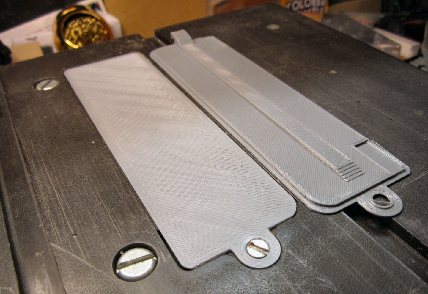
A couple things to note about resin printers. The resins are generally toxic, so keep the printer away from children and animals. The resin print is brittle, so be careful handling it. The resin has a shelf life after opening it, so a large resin printer may be expensive to feed, if you are doing small volumes of prints. (OK, three things, but I can't count well).
-
-
-
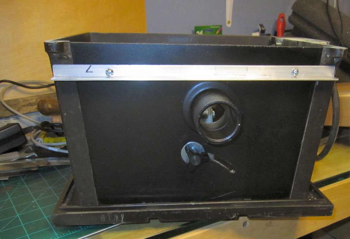
Part 008
I also bought three Zero Clearance plates for the saw, from Radical RC.
The center ridge you see on the bottom of the uninstalled one acts as a stiffener and the rear clamp.
When I installed the one shown, I had to press along the edges, after tightening the screw, to snap it flush over the whole surface.
I have not run the blade up through any of them yet. I’ll wait until I’m ready to use one. I don’t want to keep putting them on and off, in case doing so shifts them a little, after the slot is cut.
They are ~$10 US each, so not a bad deal!
I also bought a better miter gauge, off Ebay, from the same seller as the backplate, and rip fence. I’ll review that when it comes in.
-
Part 007
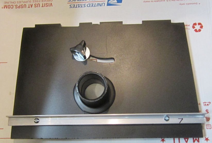
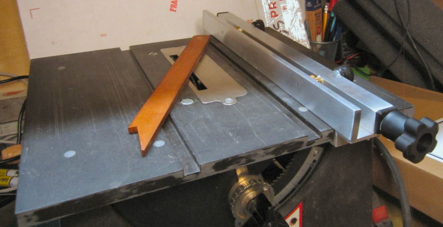
I bought two new parts for the saw, a backplate and a new rip fence. I got both off of Ebay, from a gentleman who says he has been making them for years. He plans to continue offering them through Ebay.
A. The Backplate
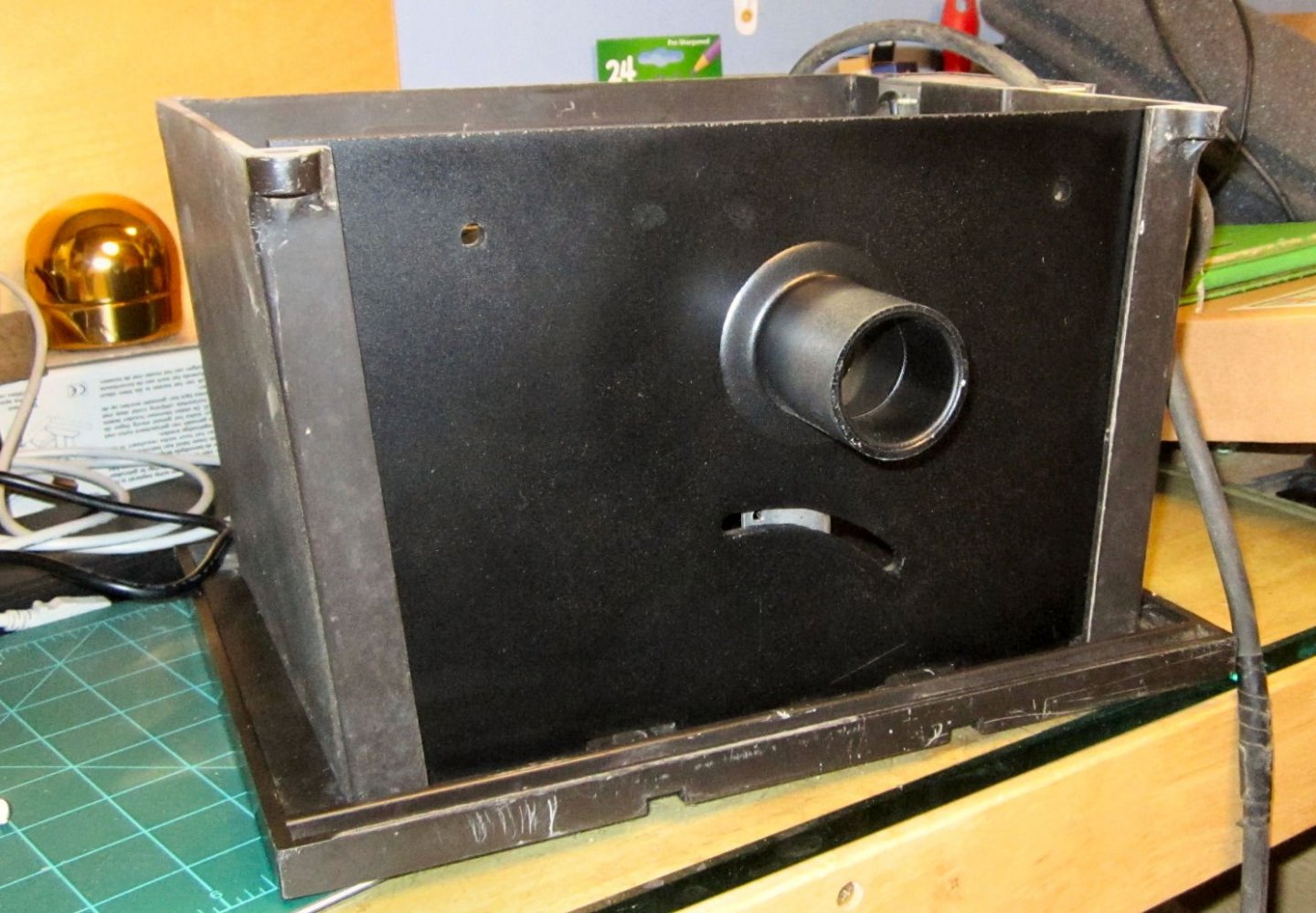
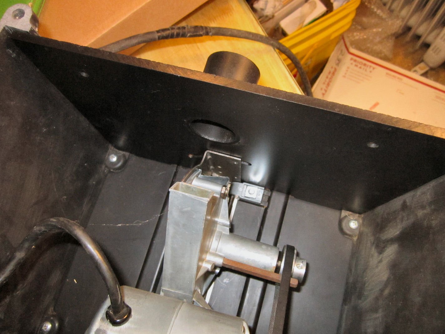
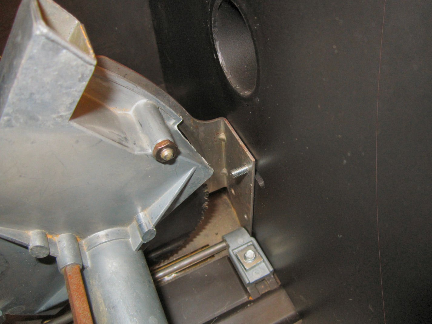
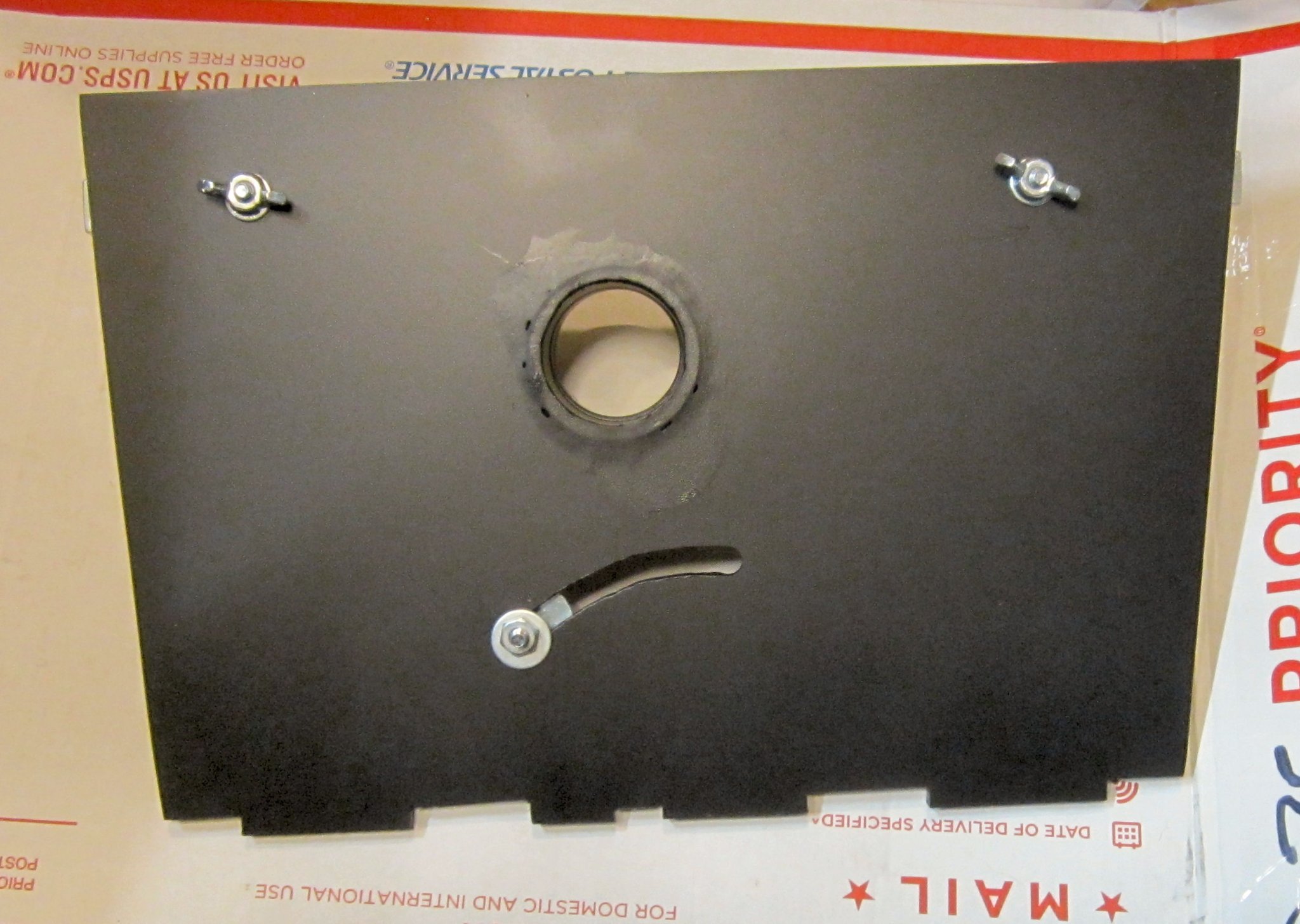
The back of the saw is open, from the factory, and this plate fits in the empty space. It thus closes the back from any things that might otherwise, accidentally intrude back there. It provides a port to attach a shop vac, which with the back plate on will actually do some good. It also braces the sides of the base to stiffen it. The other important item it provides is an additional lock for the back of the saw blade housing!
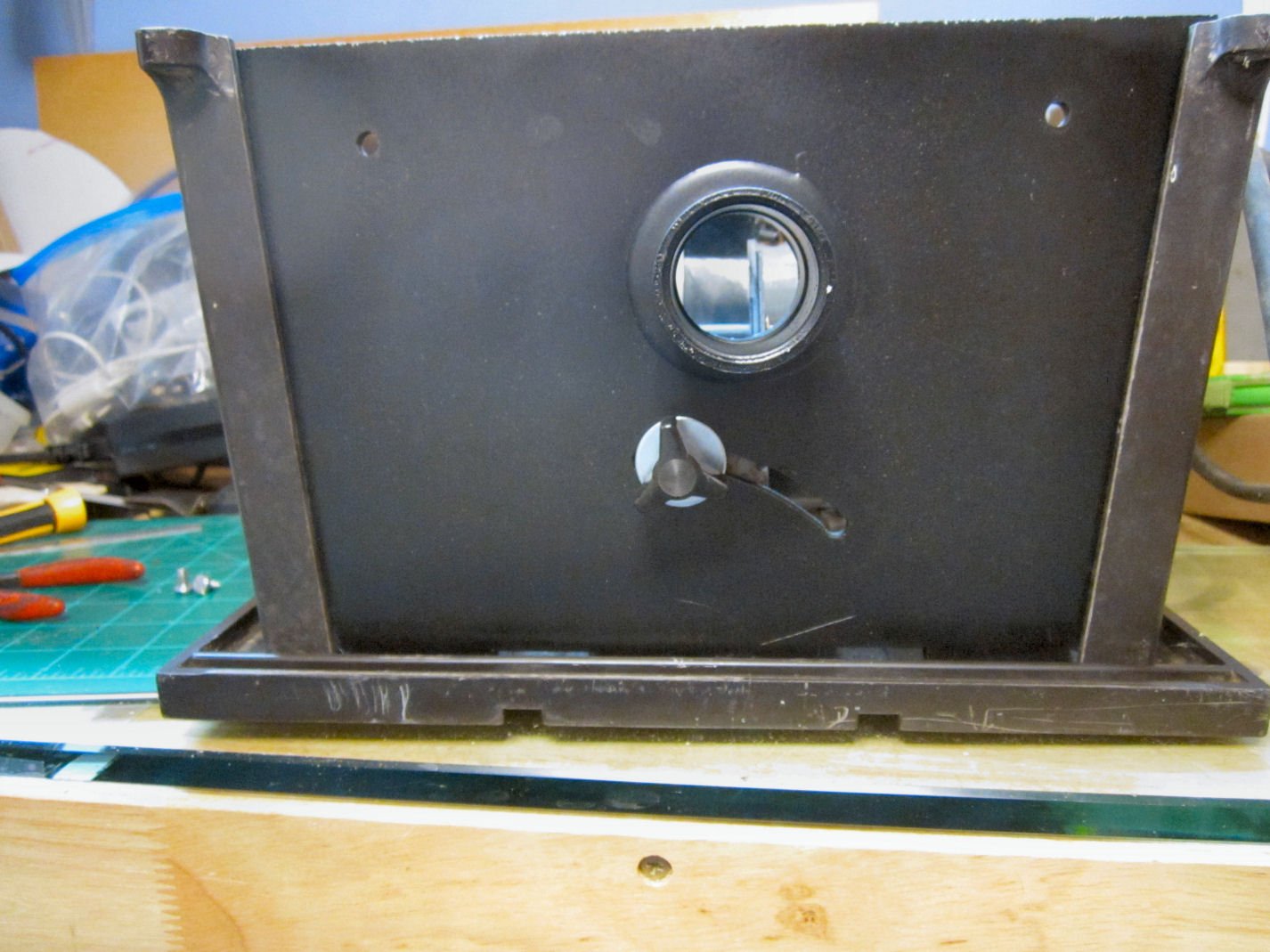
This picture shows the outside of the plate (once installed). The knob in the curved slot is the rear blade housing lock. The aluminum angle bracket is the brace. Of course, the tube is the vacuum hose attachment port. The castellated top fits into the groves of the underside of the saw table.
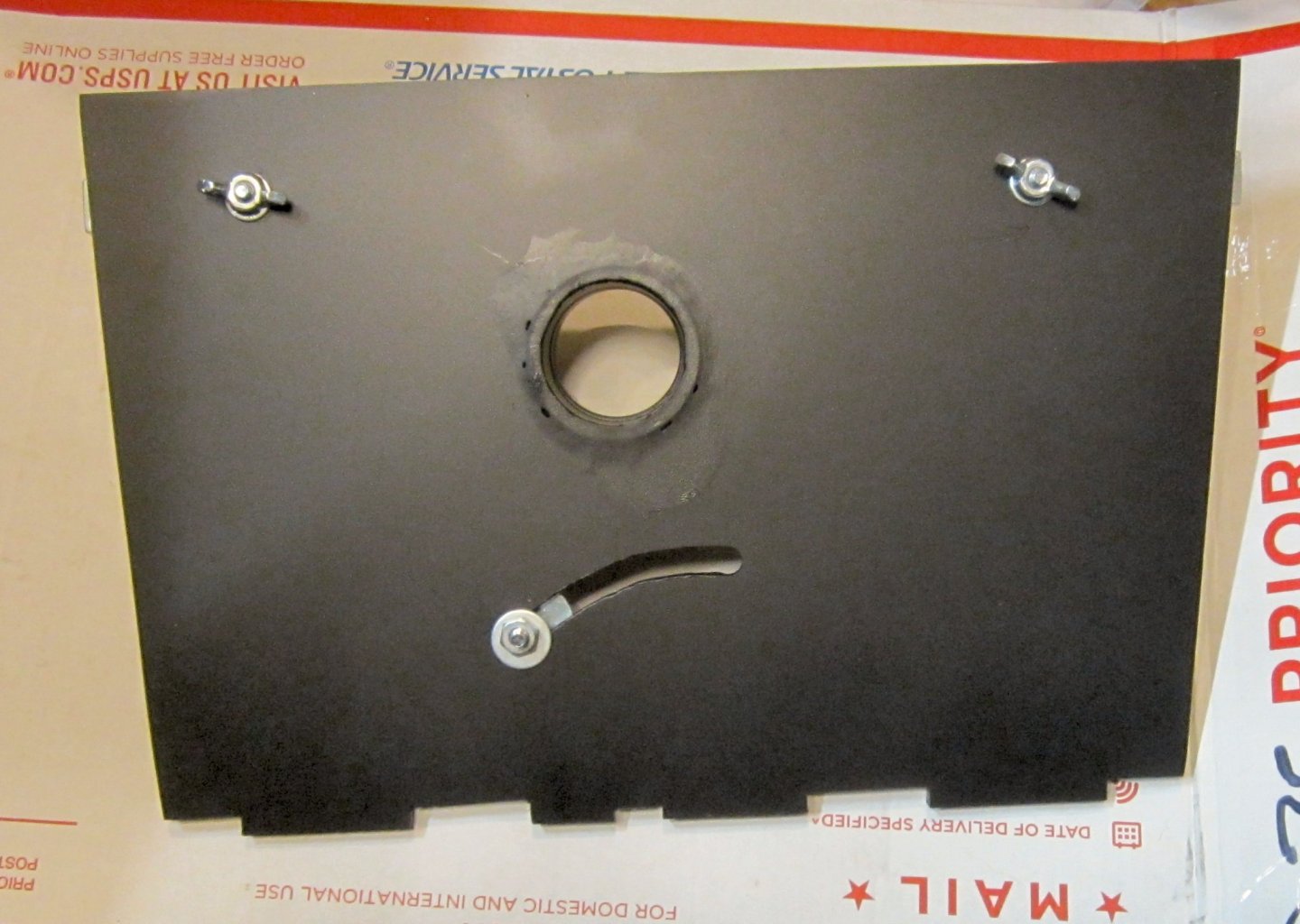
This is the inside of the plate. The nut on the shaft of the knob, is just to hold it during shipping, and will be discarded. The wing nuts are used when attaching the brace.
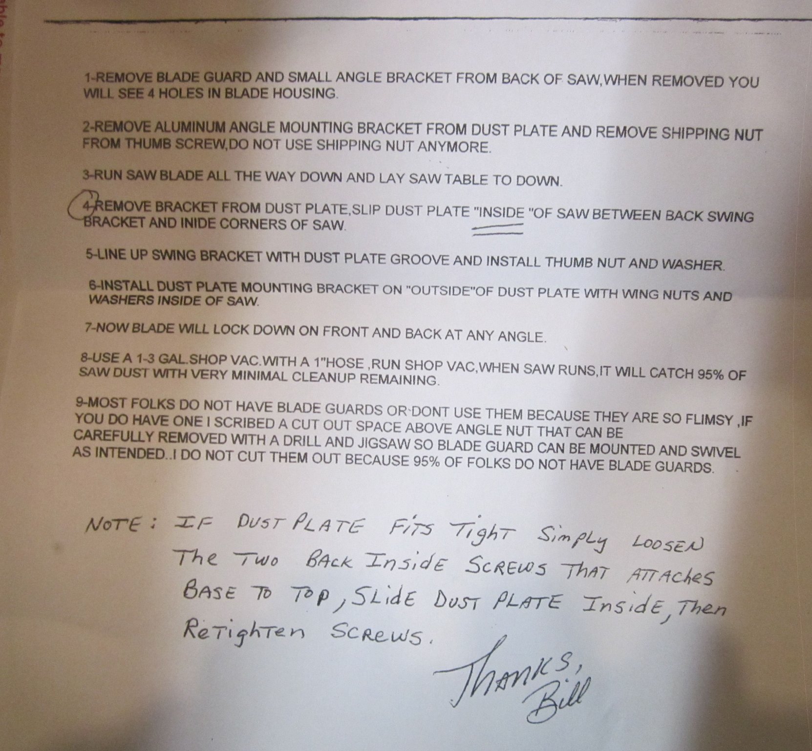
Here is a picture of the instruction sheet.
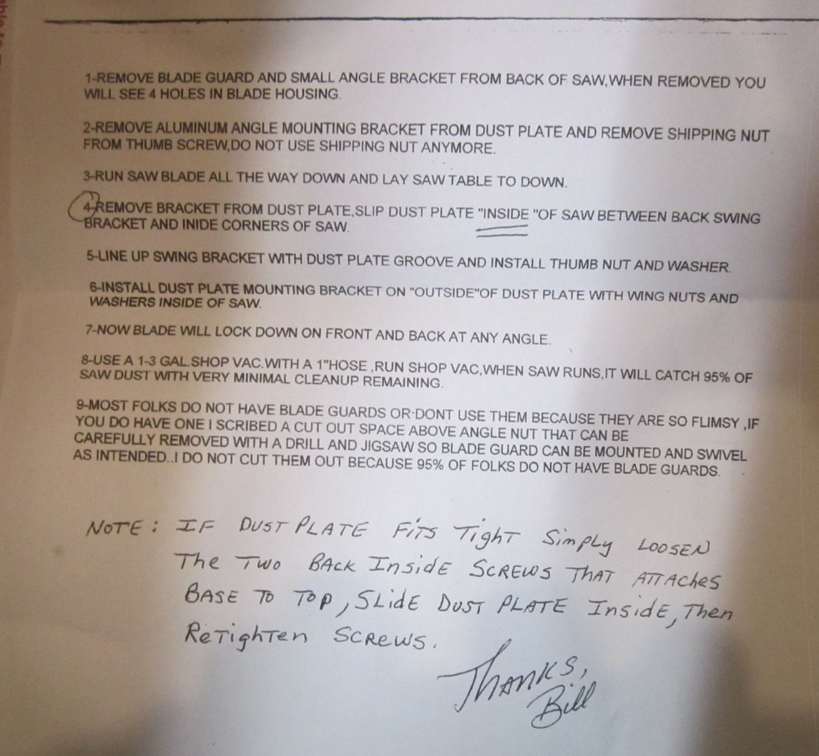
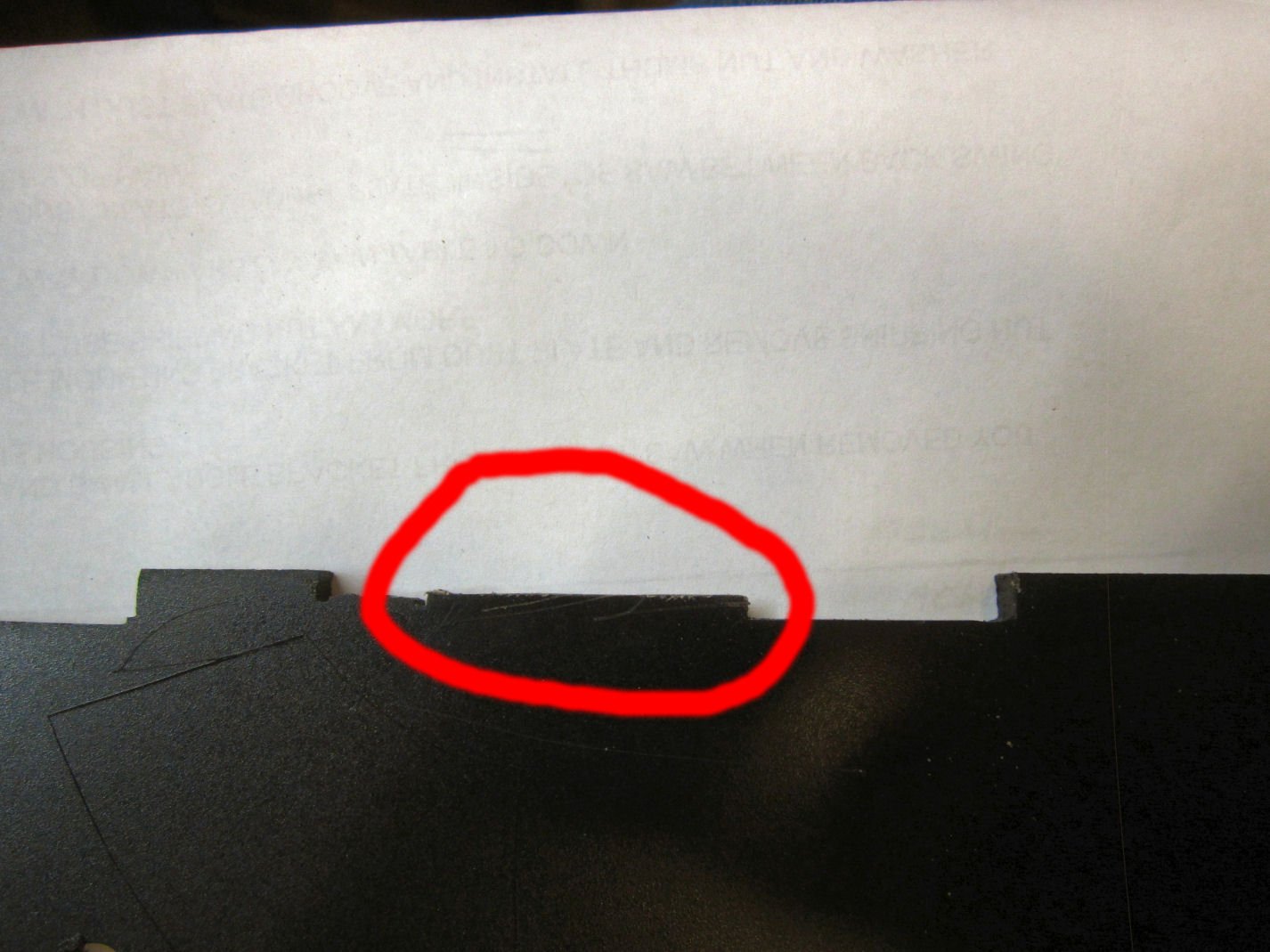
When installing the backplate, you must either discard the little rear blade guard, or figure out an alternate mounting for it. The backplate fits in tight against the blade housing, so the guard would have to be moved to the inside of the housing. If you look closely at the first picture, you will see scribed lines marking the area you would have to remove to allow for new mounting screws. I chose to simply remove the guard, as the plate seals this area anyway.
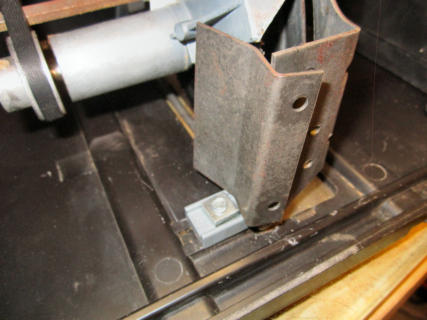
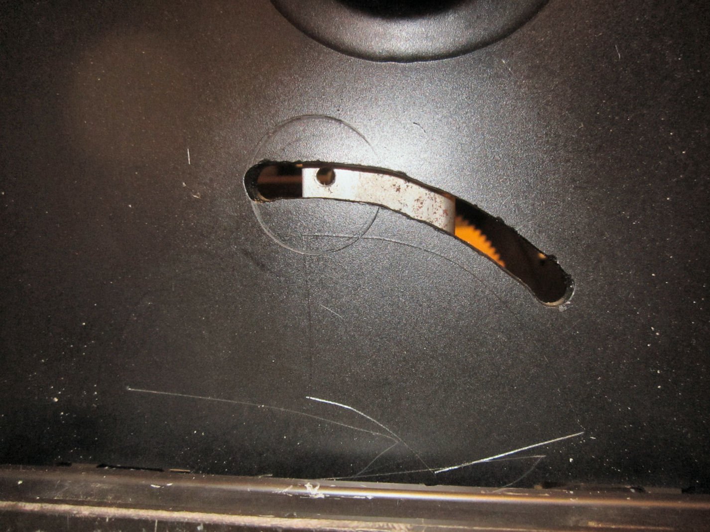
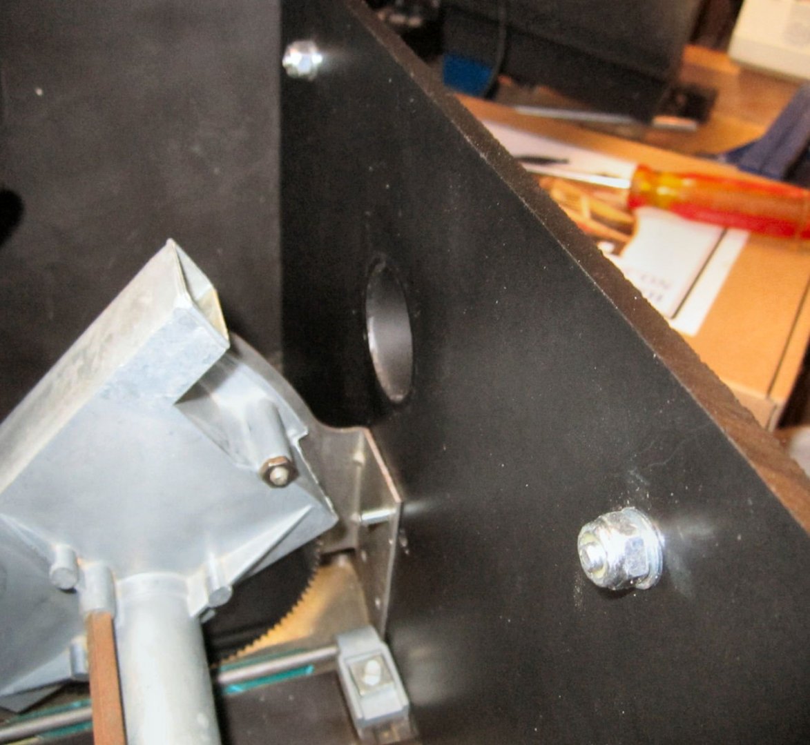
The upper screw hole in the housing is where the new knob will screw in.
The plate is slid in inside the opening and sits down onto the bottom of the table, between the housing and the adjacent ridge.
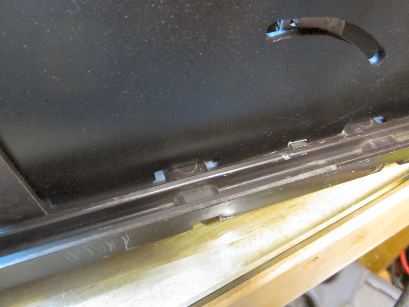
I found that the plate did not fit solidly to the bottom of the table, which has apparently bowed just slightly over the years. This allowed the plate to rock a bit, so I cut a little off of the longer parapet area in the center. Now the plate sits firmly against the table. One effect of this was that the plate sat a little further down causing the knob shaft to rub on the plate. I filed the slot a little wider to fix this.
Here are shots of the plate in place.
Next the rear brace is installed. Check the fit, as the attachment screw holes are not symmetrical with the center of the base, so the brace only fits with the horizontal lip toward the table. I replaced the wingnuts with 10-24 nylon locknuts. Tighten the nuts down until the nuts on the brace touch the plate. This holds the plate firmly in place. In addition I’m going to drill a hole through the two lips on the base to insure that the plate can’t shift during sawing.
B. The Rip Fence
The Rip Fence is a big improvement over the factory one. It clamps more securely and has an adjustable fence blade. The fence clamps front to rear, like a full size saw fence, not just with a clamp under the front lip, like the factory one. The back of the factory fence is free floating, being held square just by the stub on the clamp casting on the front of the fence. The new fence is also taller than the original, allowing for more controlled cuts. The new fence can be fine tuned to your saw table, using the two adjustment screws on the main body.
The manufacturer also included a nice push stick with it!
For my saw I had to fine tune the front lip. As there were a few burs and dings on it. I used a large flat mill file on the front and under the front lip to smooth things out. This is why there are gray areas in the last picture, that is the bare plastic showing through.
The adjustment also comes in handy, as I found the front lip to not be perfectly straight on mine. So I can now adjust the blade, if needed, for each fence position. The error is not very large, so most times I will not have to worry about it.
-
-


Muscongus Bay Lobster Smack by bobandlucy - FINISHED - Model Shipways - Scale 1:24
in - Kit build logs for subjects built from 1851 - 1900
Posted
Imaginative fix on the spine!