thibaultron
-
Posts
2,646 -
Joined
-
Last visited
Content Type
Profiles
Forums
Gallery
Events
Everything posted by thibaultron
-
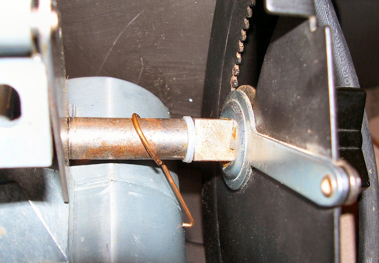
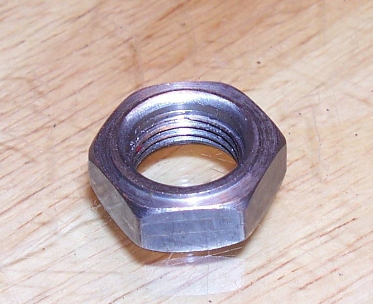
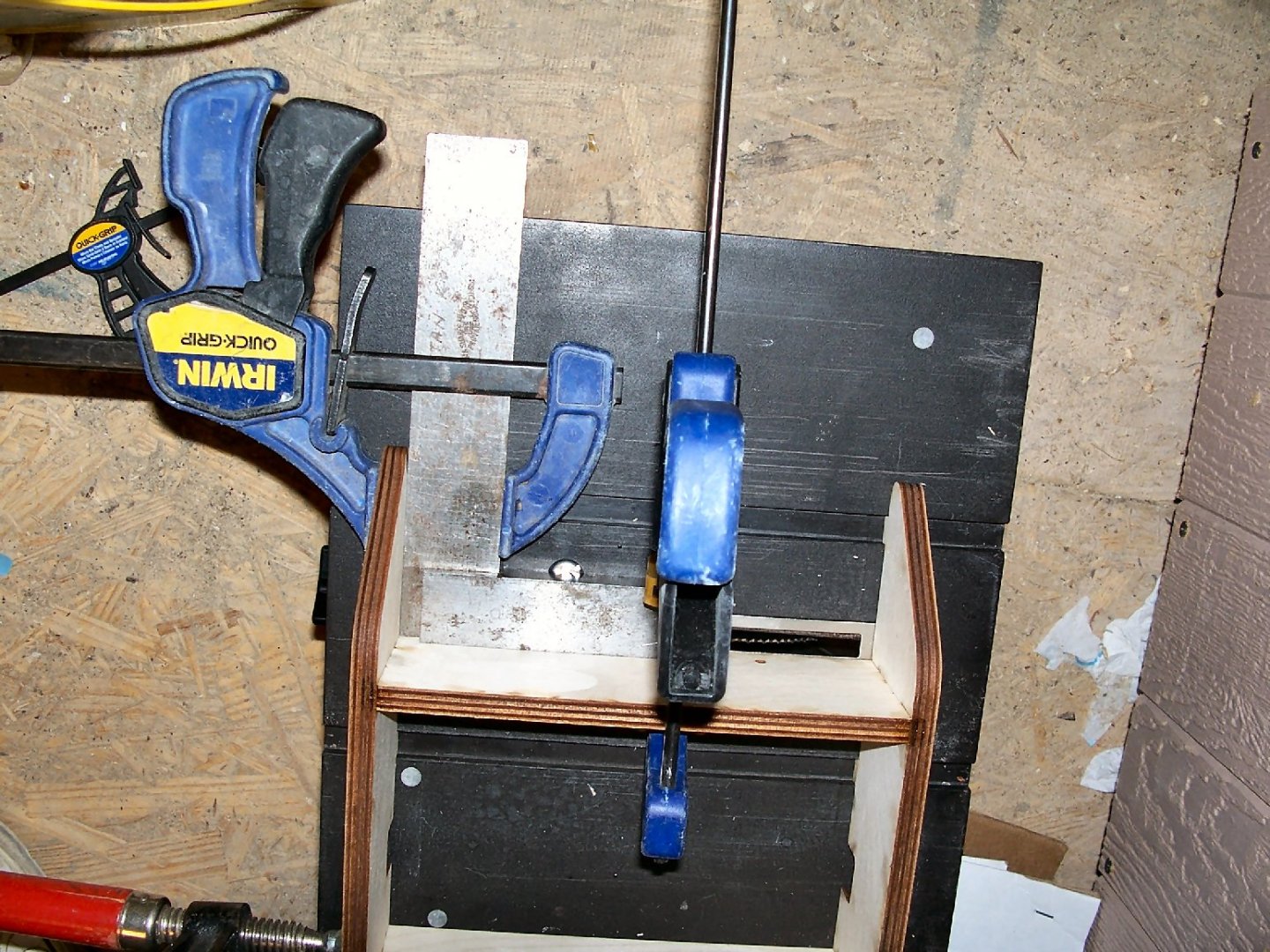
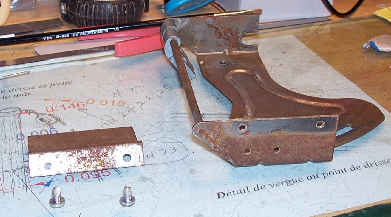
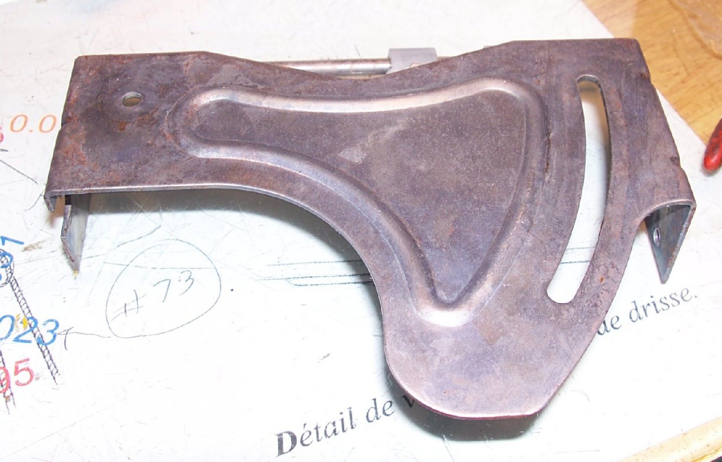
 Part 005 I stopped by Lowes today and bought some nylon washers, for the saw. I bought #10 washers for the blade drive assembly, and ¼” washers to fix the blade angle/lift mechanism. The #10s will replace the Mylar washers I installed earlier. I have a better feeling about their durability. The blade tilt/lift assembly was loose and allowed the mechanism to flop around a bit. Maybe not a problem, but I don’t want it to change angle, even slightly, while I’m cutting. The shaft that raises and lowers the blade, runs through the center of the block that adjusts the blade angle, there is a gap between this shaft and the block that allows the assembly to flop a little. I slit one side of two of the ¼ inch washers and inserted them into the gap (yes it was “fun”). This tightened up the assembly quite well. By the way the copper wire you see, is suppose to be the spring that holds the shaft into position. Being copper it does not hold very well! I’ll make a new one out of some brass or steel wire. There is still enough movement that I think I’ll add a second adjustment point at the back. Nothing fancy, just a curved slot with a screw I can tighten when I get the blade at the angle I want. In anticipation of this I installed the angled blade cover on the inside of the assembly, rather than at the back, like it came from the factory. I’ll grind the ends of the screws off, when I build the back.
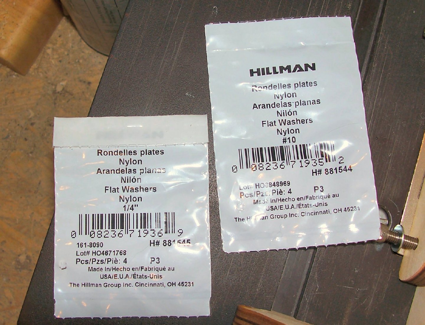


-
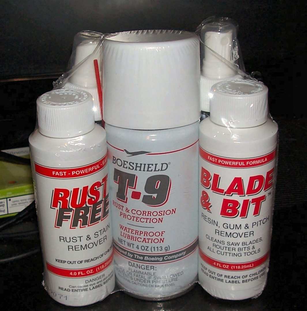
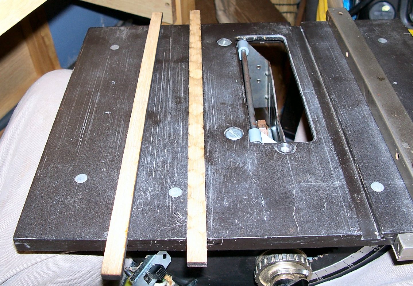
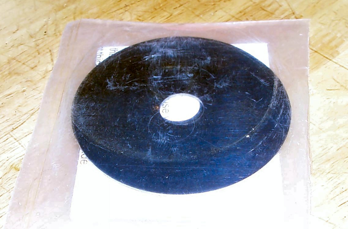
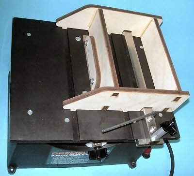
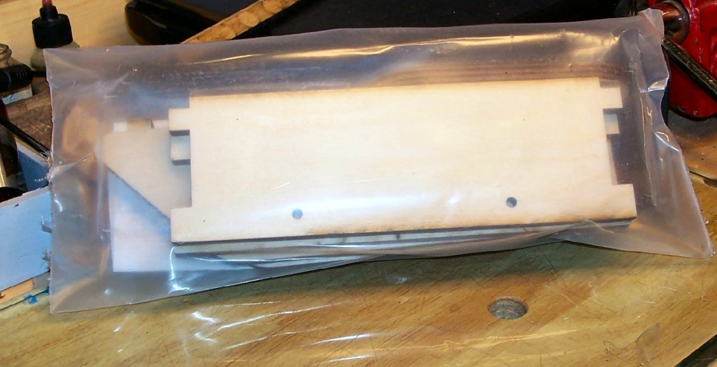
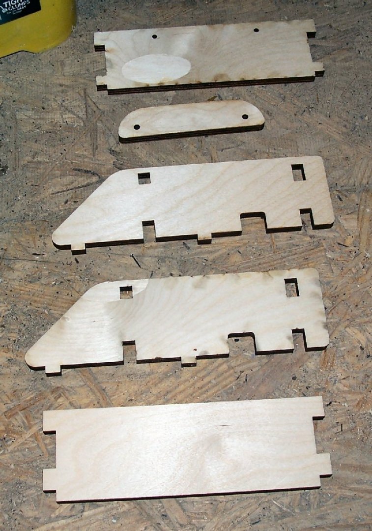
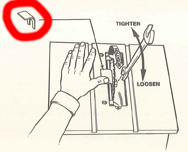
Part 004 A quick review of the Boesheild products I used in the last installment. The Rust and Stain remover and the blade cleaner, both worked well. The protectant did not work as well as I had hoped. The metal stayed “wet” and after several days I had to wipe the parts off to get them to dry. I think that there is a wax coating on them, only time will tell. I ordered some accessories from Radical RC for the saw. https://www.radicalrc.com/category/Table-Saw-Dremel-Accessories-492 Here are shots of the parts. I’ll describe them as I go. These are laser cut slides for the miter slots. I’m going to use them to make a sliding table for the saw. These are support disks for use when you are using thinner blades than those the saw was designed for. These blades are typically the modern high tooth count ones such as 100 or 200 tooth blades. If I’m using the 100 tooth original Dremel 8004 blades, these are not needed. There are two disks in the package, one is placed on each side of the thinner blade. They both add stiffness to the thin blade and bulk out the total thickness so the factory nut can clamp the assembly. Without the support disks, the blade alone would be too thin for the nut to clamp the blade. This is a nut that is machined so that 5/8” arbor blades can be used on the saw, which is designed with a ½” shaft. This allows me a wider selection of blades to be used in the future. The last part I bought is an alignment jig for setting up the saw. Once built, it allows quick setup of the blade mechanism. The jig holds the blade vertical, and square to the miter slots. You loosen the blade assembly hinge bolts and clamp the blade in the jig. You can then tighten them, and the blade will be parallel to the miter slots. You then can move the blade tilt marking plate so that it falls at the zero degree mark. The jig also holds the fence in position, so that you can tighten the bolts that hold the fence body to the fence clamp, insuring that it is also parallel to the blade. Here is a picture from the catalog. Here is the package and the wood parts it contains. There are also two screws and washers for installing the clamp piece (the smallest wood piece). You are to assemble the parts on the saw table, and use a square to align the body pieces, then wick thin superglue into the joints. These photos shows the parts assembled on the table, with a machinist square clamped on to hold them square. I wish I’d had another long clamp for the other joint area, but I was able to hold the pieces with my hand. I carefully wicked in the glue one joint at a time, and let it set before moving on. I even managed not to glue the jig to the table! If I had a smaller square I would have clamped it inside the assembly rather than how I had to clamp the larger one. Once the last joint was set, I removed the jig, and wicked in more glue along the lengths of the joints. Here are a couple shots of the finished jig. I still have to install the clamp. I could not locate my Allen wrenches for the cap head clamp screws, yesterday. I’ll find them the next time I get to the shop. Next month I’ll buy a couple of the blank 3D printed saw blade inserts, and their aftermarket miter gauge. I also drew up a insert blank on my CAD program, so that I can design my own future inserts.


-
Use a modeling putty, not bondo! The bondo is much harder than the wood and would be difficult to sand without cutting into the wood. When you go to paint the model, seal it with shellac or varnish, before painting, if you will be using acrylic paints. Do a search in the forum, there was a thread a little while back , on the various methods of sealing recommended.
-
Well done!
-
I found the book both fasinating and helpful.
-
In model railroading, you can find a prototype for just about anything. One of the hard and fast rules, though, is never put a window in a chimney. However, when I lived in Pittsburgh, there was a house with just such a window in the middle of the chimney! A couple of years ago I found the house on Google Maps, and the street view shows that the chimney and window are still in place!
-
Chesapeake workboats had painted decks, so nails would not show. While the Sharpie is not specifically of Chesapeake origin, it would probably been treated the same for a similar use.
- 90 replies
-
- 1
-

-
- finished
- Midwest Products
- (and 1 more)
-
Part 003 I received the Boesheild rust converter/protector/blade cleaning kit recommended in the site I talked about earlier, and worked on cleaning up the sheet metal parts of the saw. The protectant and the resin cleaners are both recommended for wood working tools and are stated not to effect the finishing of the wood. Here are three shots of the sheet metal assembly, before I treated it. In the first shot I had already tested the rust converter on the inside of the center area. I disassembled the main and end pieces, so I could get to the area between them. I started with the smaller piece, spraying the converter on and using a green kitchen scrubby to work the solution into the pits, and loosen the flakes of rust. I then repeated the process for the rest of the assembly. The write-up I mentioned said to use a brass brush, but I could not find mine. Looking at the photos, the scrubby did not get down into all the pits, so I would recommend using the brush. In the last picture, you can see that the converter also darkened the galvanizing slightly. After rinsing the parts with water, I sprayed on the protectant. It seems to be similar to WD-40 in application. I set the parts to dry, as in the instructions on the can, and will check them out tomorrow.


-
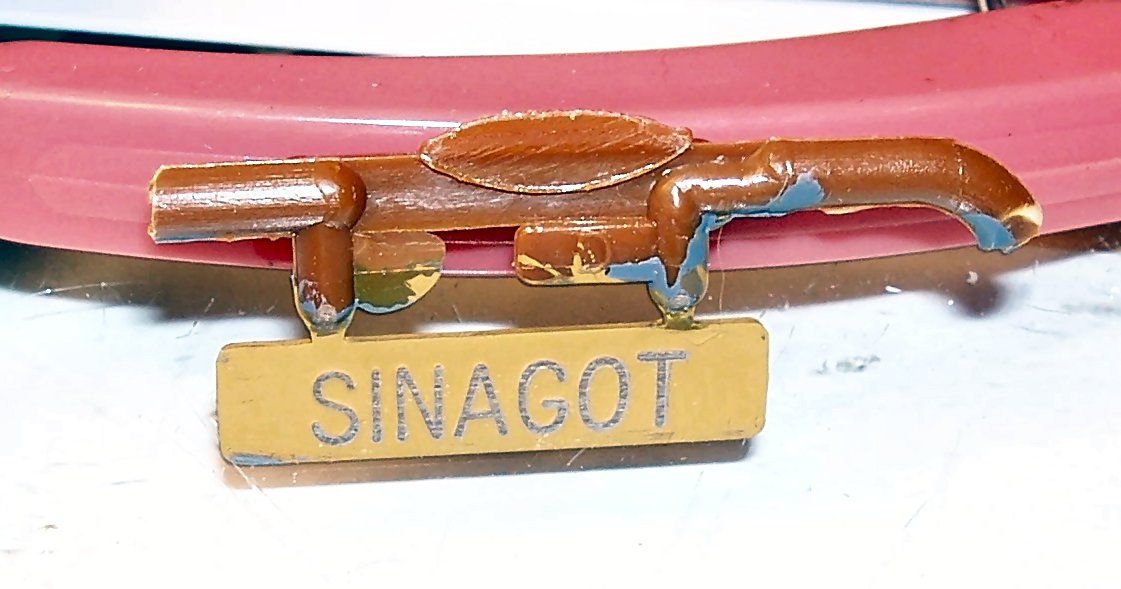
PART 14 A quick update. I sanded the faceplate to expose the original plastic color of the part, and it worked. I wish now that I had painted it with a lighter color, to make the contrast better, but you can clearly read the name. Here is a shot of the nameplate. I only had 320 grit sandpaper available, so you can see some scratches in the close-up, but not from viewing distance. I touched up the areas around the edges that also caught the sanding, and will go with this look.
-
My condolences!
-
The old kits are 1/96th solid hull, the new POB ME kits are 1/48th. The old kits come in 2 flavors. The 2nd version of the Yellow Box kits have more rigging detail shown on the plans, and the rigging is shown by red lines, helping you to distinguish them from the hull/mast details.
-
I had to go with the paint I have. It is too late to add yet another layer of paint. Even Vallejo Model Color builds up, with multiple coats.
-
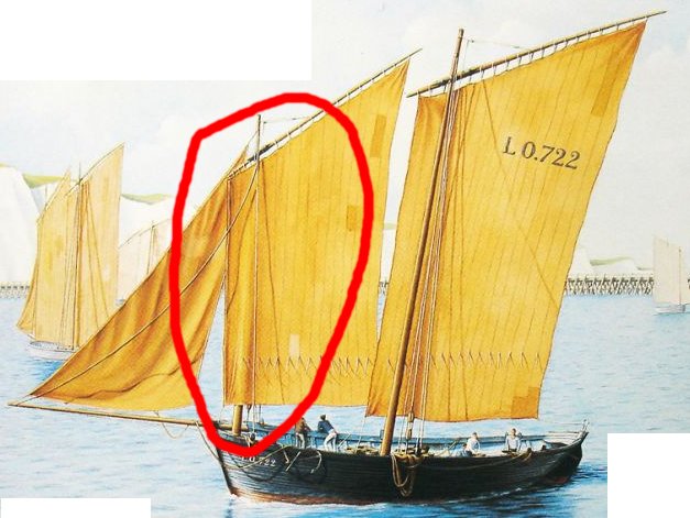
PART 13 Well, after a long delay, I’ve finally made some progress on the model! I painted the interior Vallejo “Light Blue”. This color is the closest I have to the Humbrol blue provided in the kit. As you can see in the photo , below, some of the blue got on the side of the white rail, but that is the best I can do. It is almost invisible from more than a few inches away. I will probably have to replace the plastic traveler ring, that I broke when painting the hull (in the left of the picture). I’ve tried gluing it a couple times, and have had it not hold. I’m not sure that the ring would hold up under the stress of rigging, even if it was intact. After looking at this photo, I noticed that the white primer was showing through the blue, so I gave it another coat. I painted the name plate the same color as the base and masts. I then tried a couple of different ways of highlighting the name. The first was to paint some gold onto a glass sheet and carefully press the name plate onto it, so that only the letters would get coated. This failed as the letters are too shallow, and/or the paint too thick. The paint got on the nameplate surface every time I tried it. I had similar results trying to paint just the letters. Finally I painted the whole front and sides gold, and in a day or two, I will try carefully sanding the letters to expose the brown paint or raw plastic. This “simple” build to give me a break from longer builds, has turned into an equally long one. My next major task is the sails. Do I use the vacuum-formed ones in the kit, or try to make some silkspan ones. The plastic sails would look OK, but both the larger “Square” sails are formed billowing, which is wrong for this type of boat. In the real boats each sail is set on opposite sides of their mast from how the other sail is hoisted. One sail is hoisted on the port, and the other starboard. Thus as the boat sails, one sail is always pressed up against its mast, causing it to crease where it touches the mast. This is quite unique, and I would like the model to show this. I can’t find my silkspan, however, and I’ve never made sails of any type before. This is shown on the cover of a different release of the Heller kit (circled in red). As a side note, this cover also shows that no one is minding the tiller! I once owned a 17 foot sailboat, and obtained an ad for it on the Web. The boats “spacious” cockpit was shown with 4 or 5 people occupying it! On closer inspection all the people were young children. I love ad companies!


-
A model to be proud of indeed!
-
Yes and no on the maintenance issues. Toward the end of steam, they had progressed mechanically with roller bearings and better counterballancing to where they did not require much more maintenance than the diesels, but the die was already cast. Yes they did dent the track over time, but the diesels did, and still do, wear the track just about as much, but in a different way, the drive wheels slip more and burn the rails.
-
I'll be following along too. I've read his book a couple times, and have the kit also. If you have questions, just ask the forum, they love to help.
-
If you mean kits of the same craft, yes. But they are pirated versions. No one makes a legal version of those boats, but the ones from Master Korabel.
-
The Model Shipways Emma C. Berry is a POF. I believe it is also a true POF. The Bluejacket 1/96th Bluenose, is a semi POF, as not all the frames on the original are included in the plans or kit. As for the BJ 1/48th BN and the JD, I have no knowledge of them.
-
Here is a link to a video on 12 table saw jigs. The video is for a full size saw, but the ideas can be translated to our size ones. You might find them useful.
-
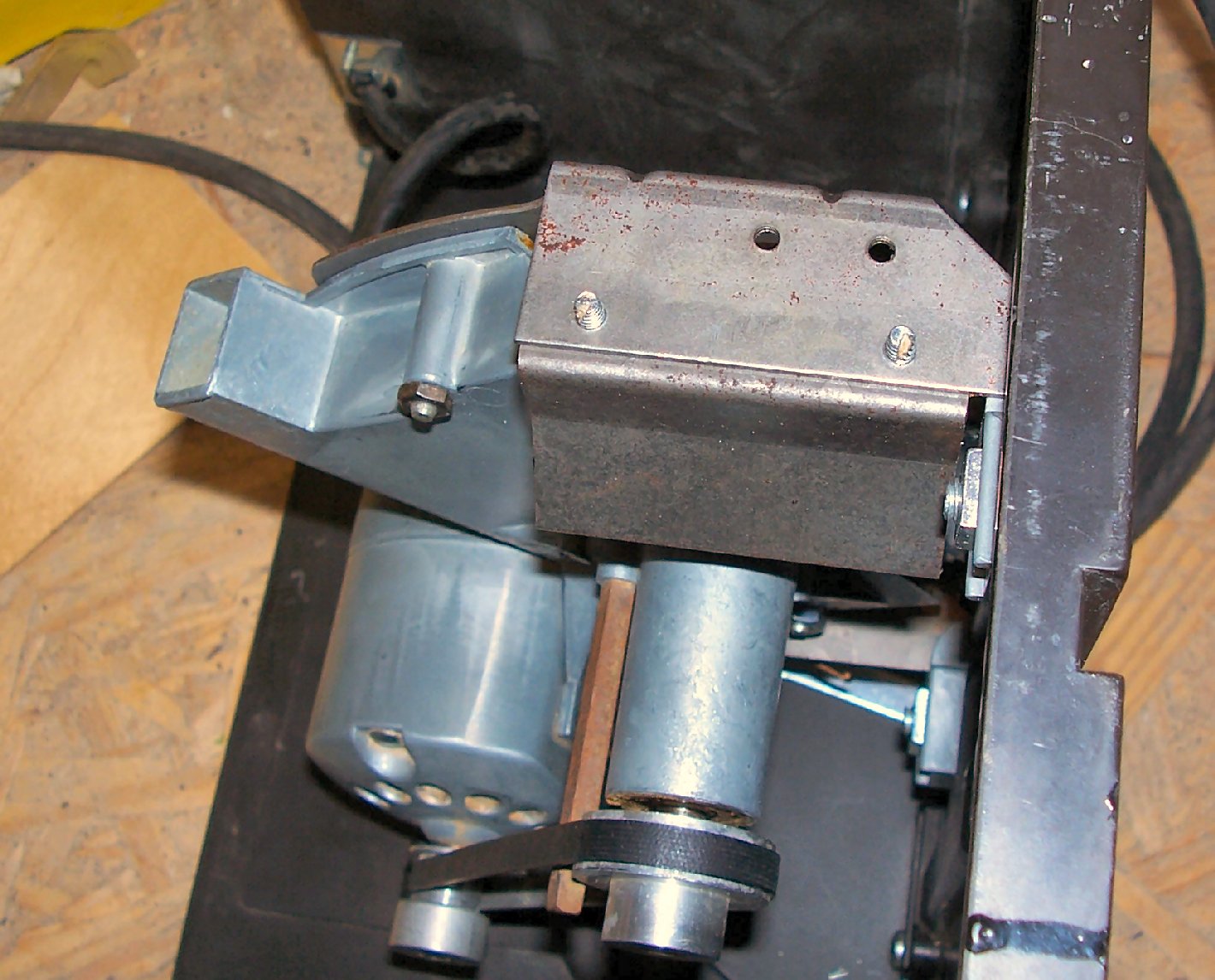
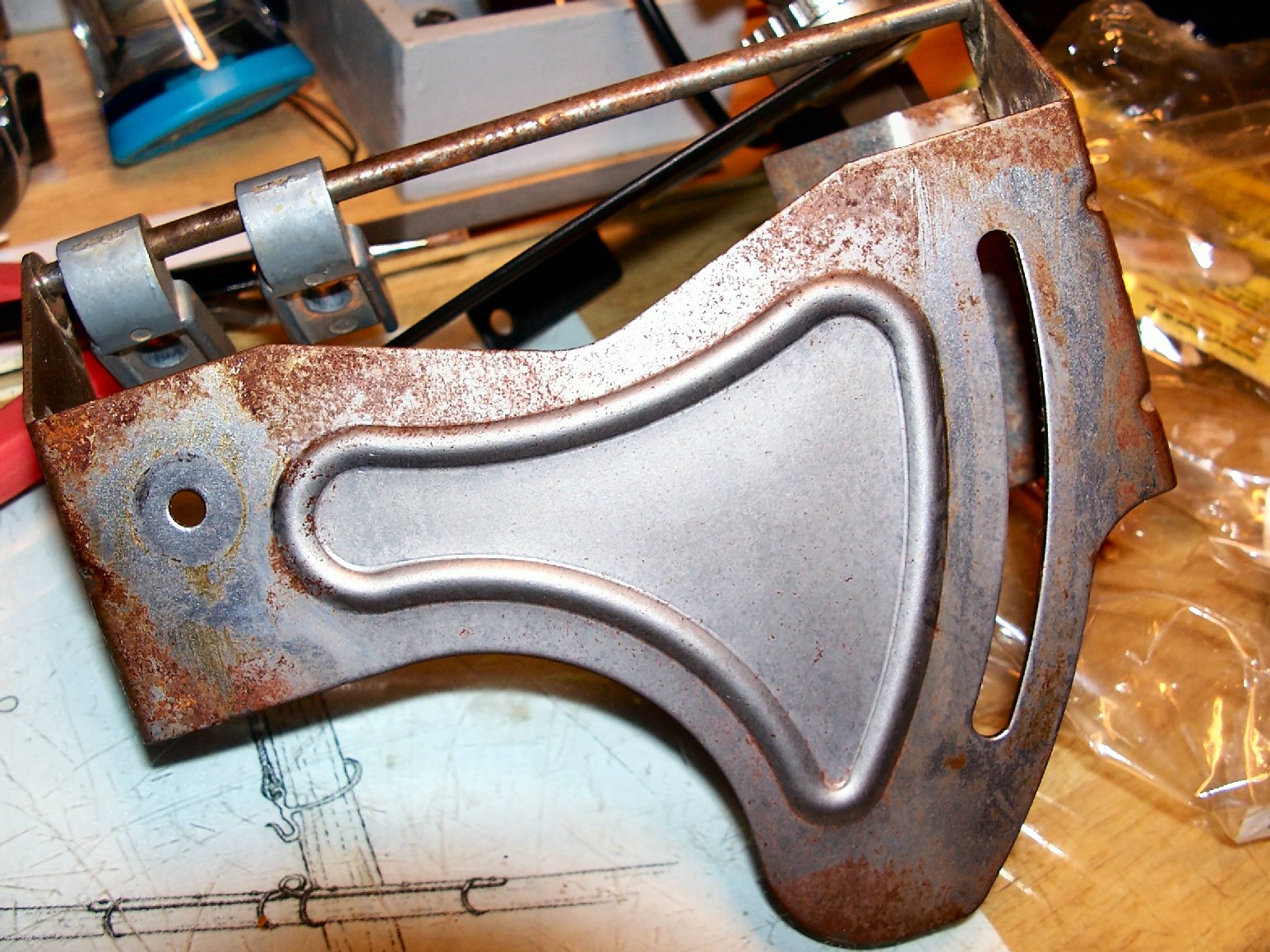
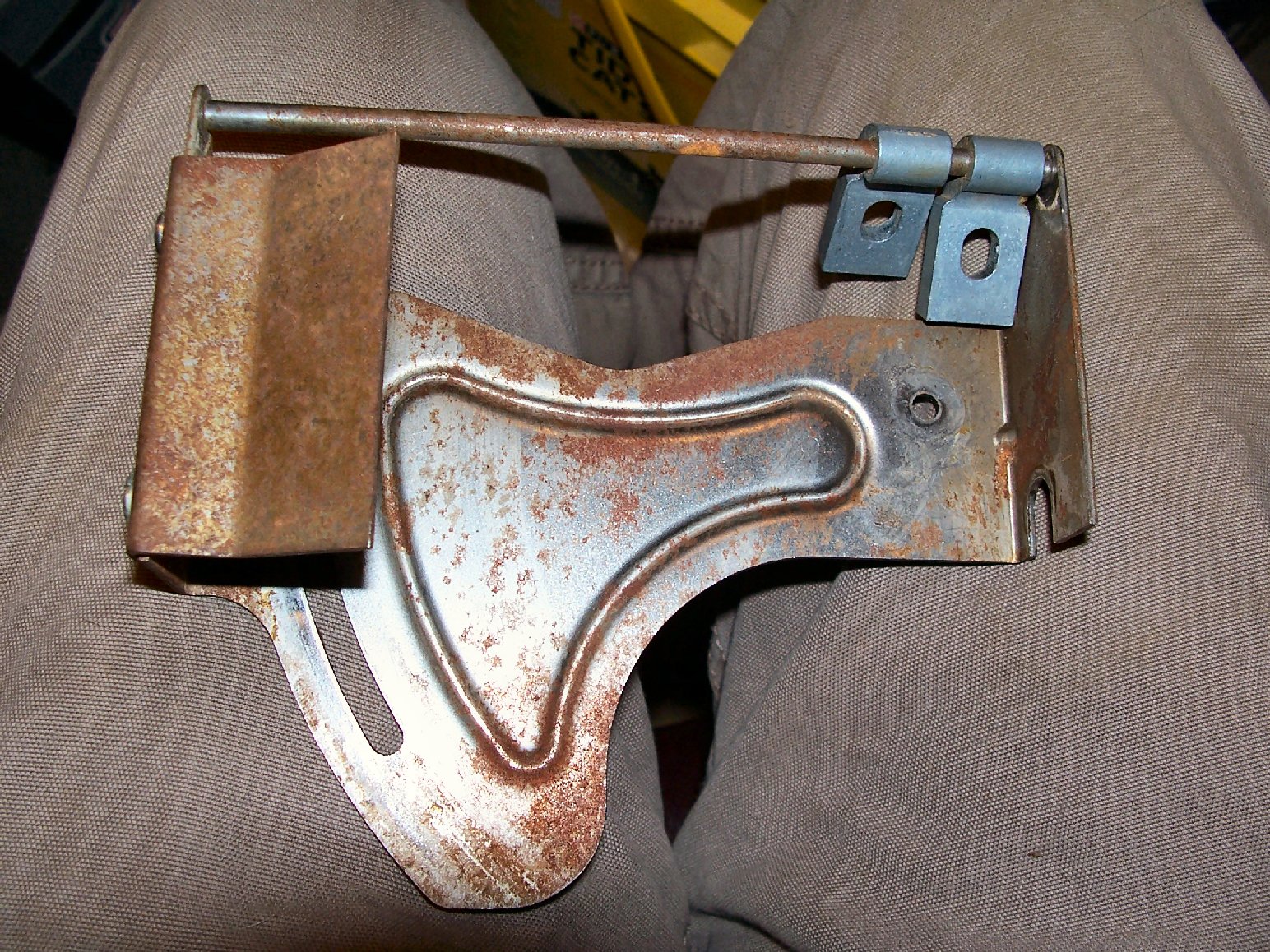
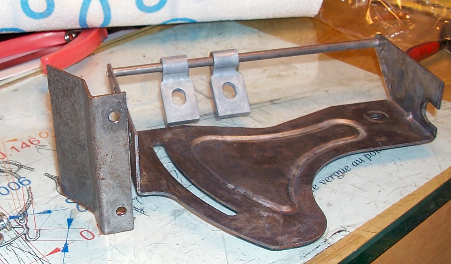
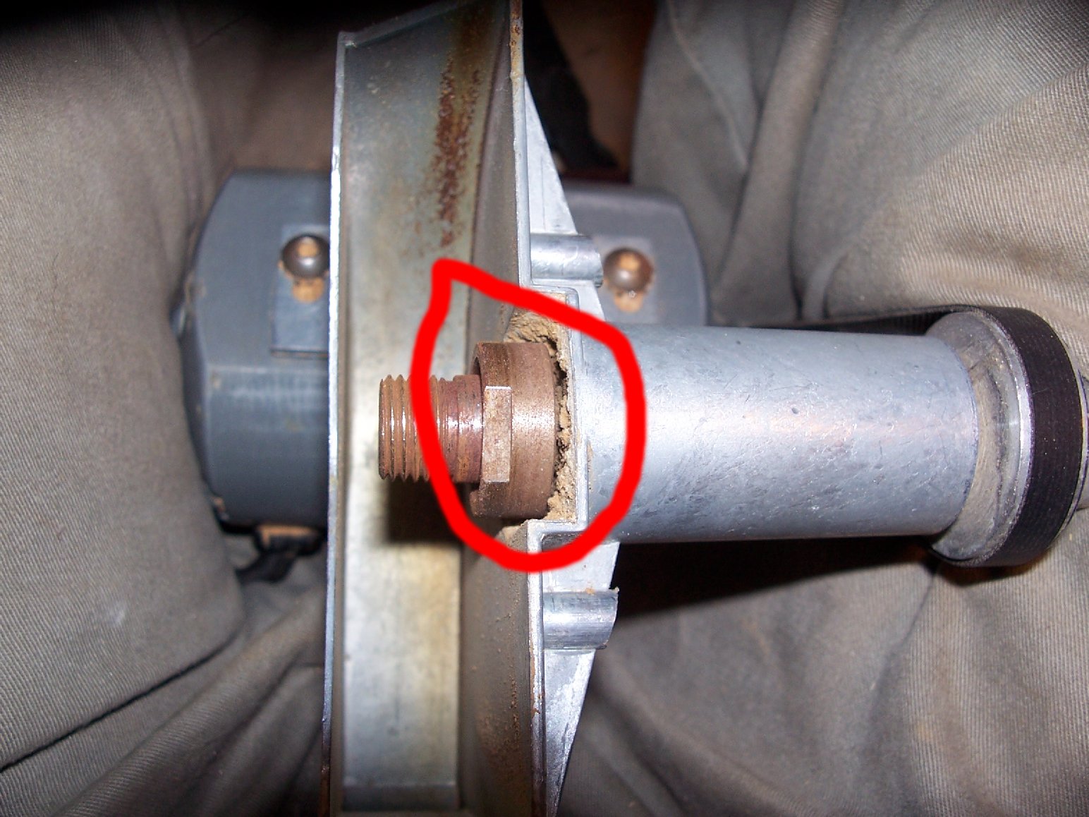
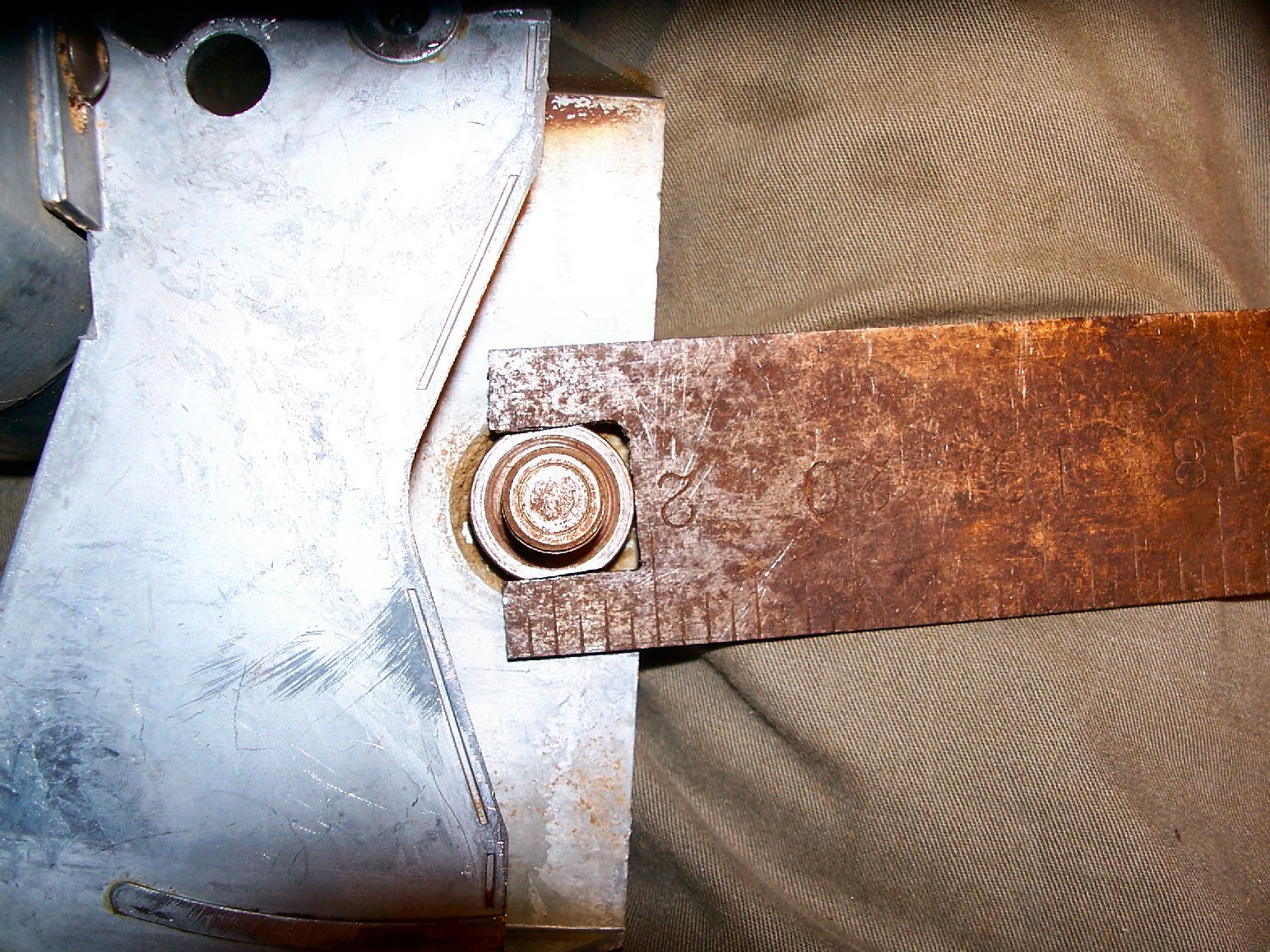
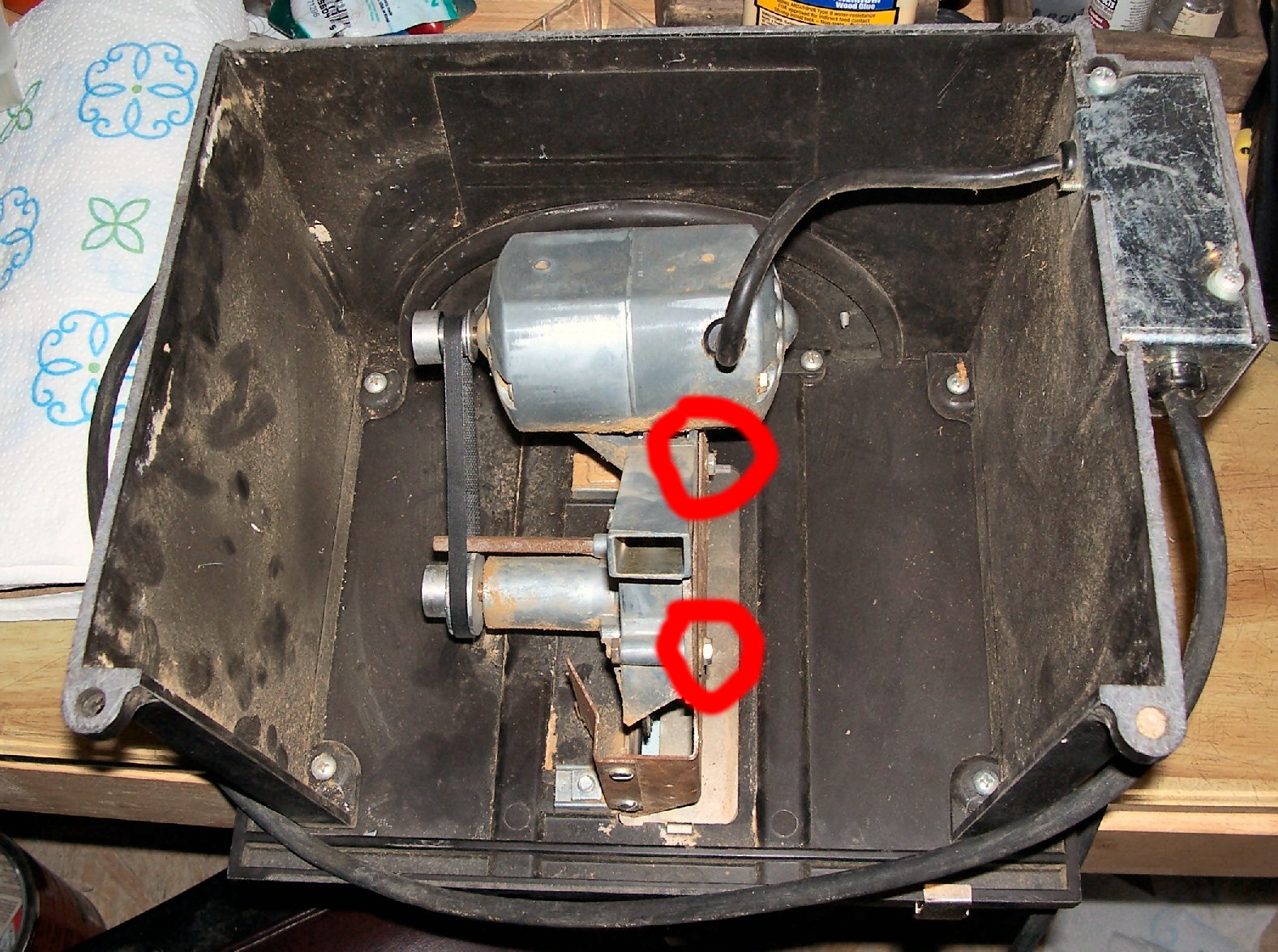
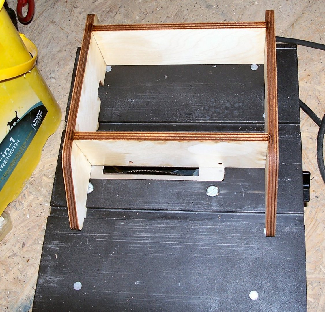
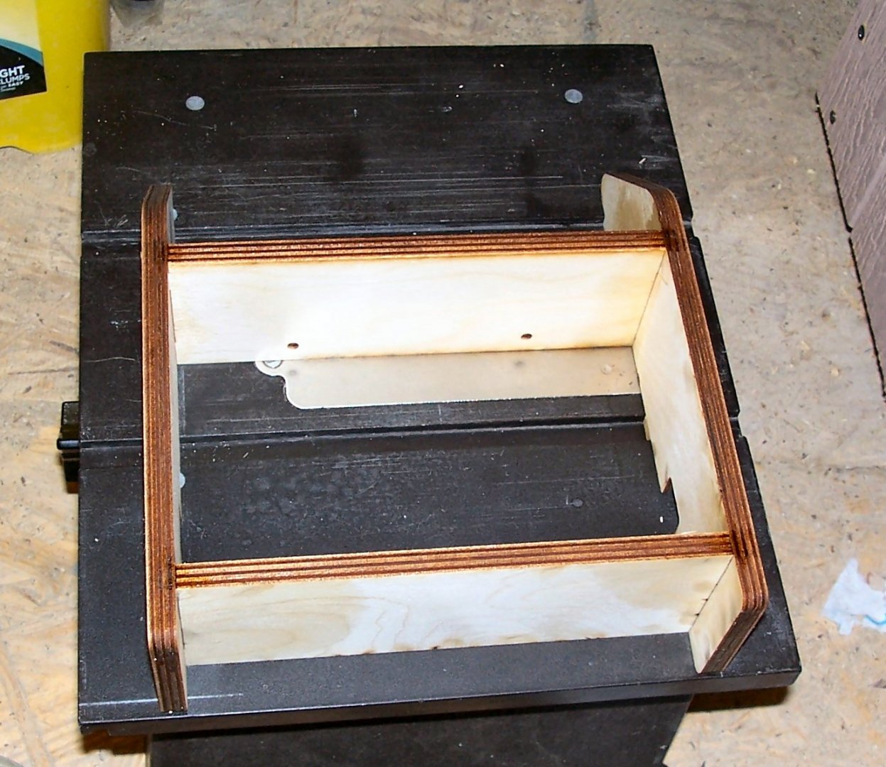
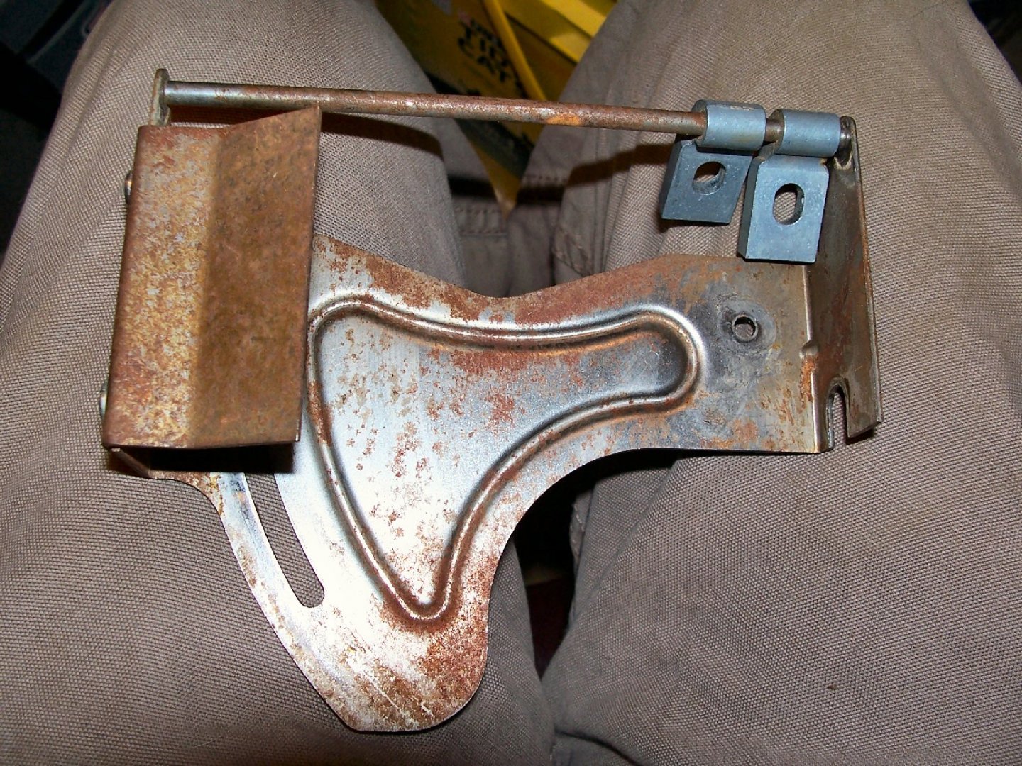
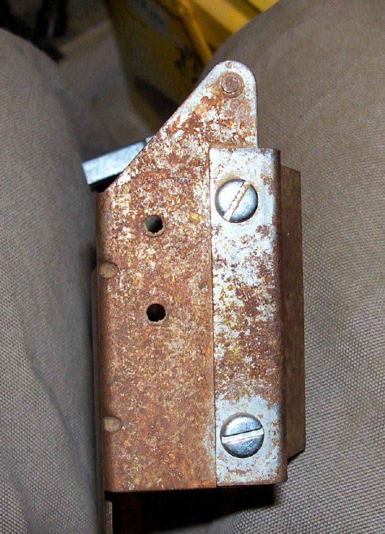
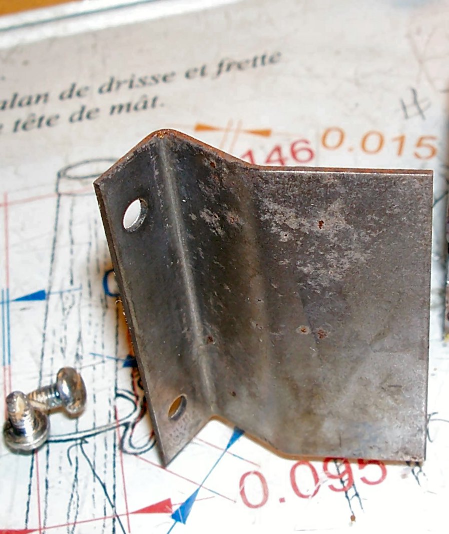
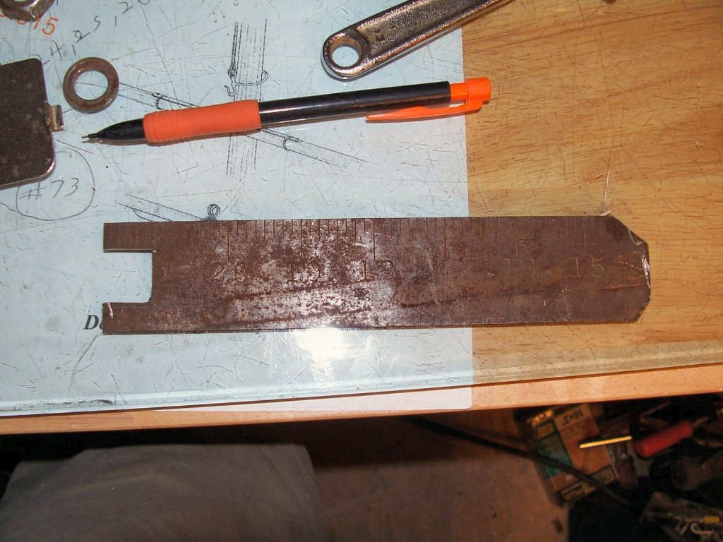
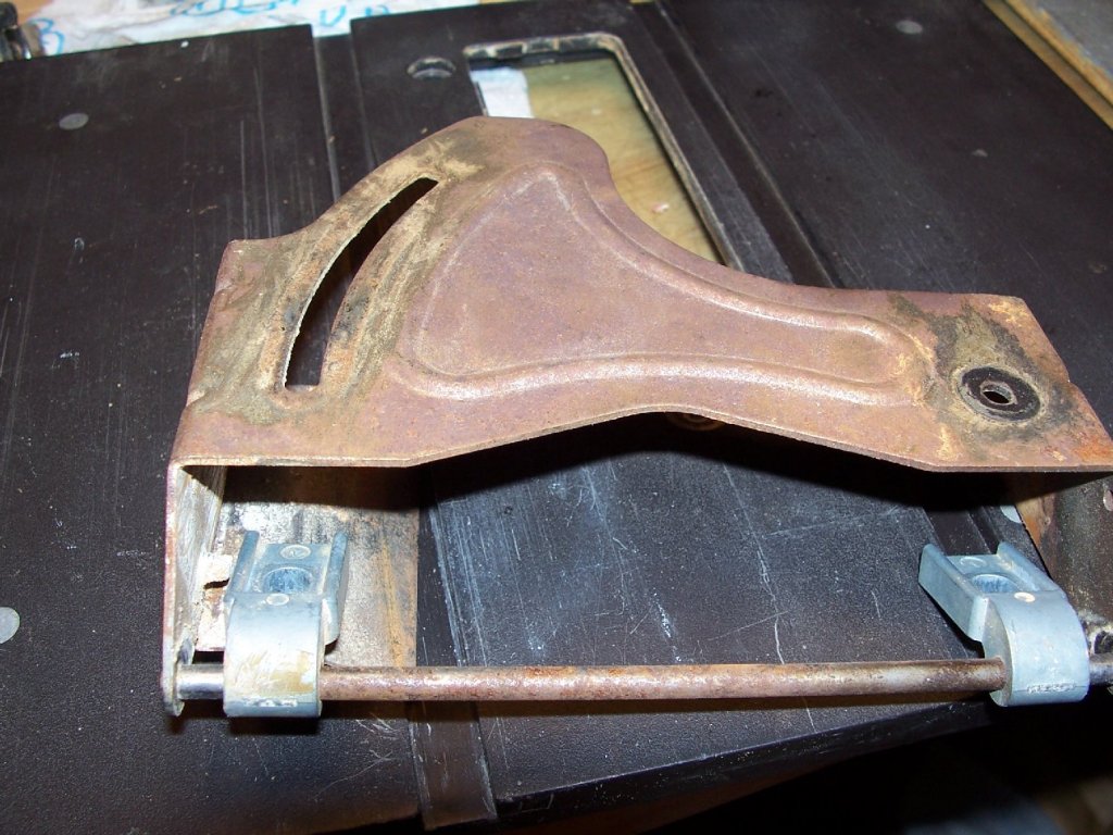
Part 002 I started working on the saw today. The first task (after I disassembled it), was to make a wrench for the blade shaft. The shaft has two flats on it to hold the shaft steady while you remove the blade nut. When new, the saw was supplied with a little wrench made out of sheet steel, shown circled in the picture below. The photo below shows the area the wrench has to fit in, with the flats circled. The space for this is too thin for a regular wrench to fit, and the Dremel part is long gone. So I made one from a piece of an old carpenters square. It is not fancy, but it works. I cut out a ¾ inch wide slot in one end with a Dremel tool with a cutoff disk, then I chamfered the other end to remove the sharp corners. The next task is to firm up the assembly that tilts with the blade and motor, to make angled cuts. The whole assembly rotates on hinges mounted on a sheet metal plate. The motor and blade assembly then slide on this plate to raise and lower the blade. The picture below shows the plate. The hinge for the assembly is one the right, and the slot that allows the motor/blade assembly to slide up and down is on the left. This shot shows the two bolts, circled in red. The saw has bolts for mounting the motor/blade assembly. The instructions say to tighten them, then loosen slightly to allow movement. This allows some slop. My idea is to put a nylon washer under the regular washers, and tighten the bolts so that there is no slop, but the assembly can still slide freely on the slippery nylon. I did not know the size of the bolts, so I bought washers for #6 and #8 screws. The store was out of the #10s. Well guess what, the bolts are #10s, naturally. I’ll stop at a different store and get some #10s. I need to buy a nut for the one screw, the factory supplied one is missing. The housing is taped and the nuts are used as lock nuts, once the bolts are adjusted. The hinge/plate assembly is tight, so there is no slop in it, though there is some flex. There is another area that allows some slop, and once I correct this, I’ll see if I have to further work on this problem. I also need to clean up the rust and add a protective coating to the steel parts. I’m a little short on funds, so that will have to wait until next payday.


-
Machining copper stock.
thibaultron replied to mtaylor's topic in Modeling tools and Workshop Equipment
On the stripe of oil on the wall behind the lathe. I bought a large piece of formica and leaned it behind my lathe, resting the bottom inside the chip pan. This kept the residue from the wall. Eventually a little got on the ceiling but that was over a few years. I use cutting oil for all my machining. There are various types for different metals, but the regular ones for steel work, if that is all you have. I never turned copper, so I do not know if there is s specific one for it. -
Looks great! Wish I could get one of mine to look half as good!
-
The above link is for the model 580-2 (The second version), here is a link to the revised 580-2 model parts list. http://vintagemachinery.org/pubs/1798/1665.pdf Here is a link to the original model manual, circa 1978 http://vintagemachinery.org/pubs/1798/17162.pdf