.JPG.ca33079f5815b861e67b9c2cccd37982.JPG)

Blue Ensign
-
Posts
4,262 -
Joined
-
Last visited
Content Type
Profiles
Forums
Gallery
Events
Everything posted by Blue Ensign
-
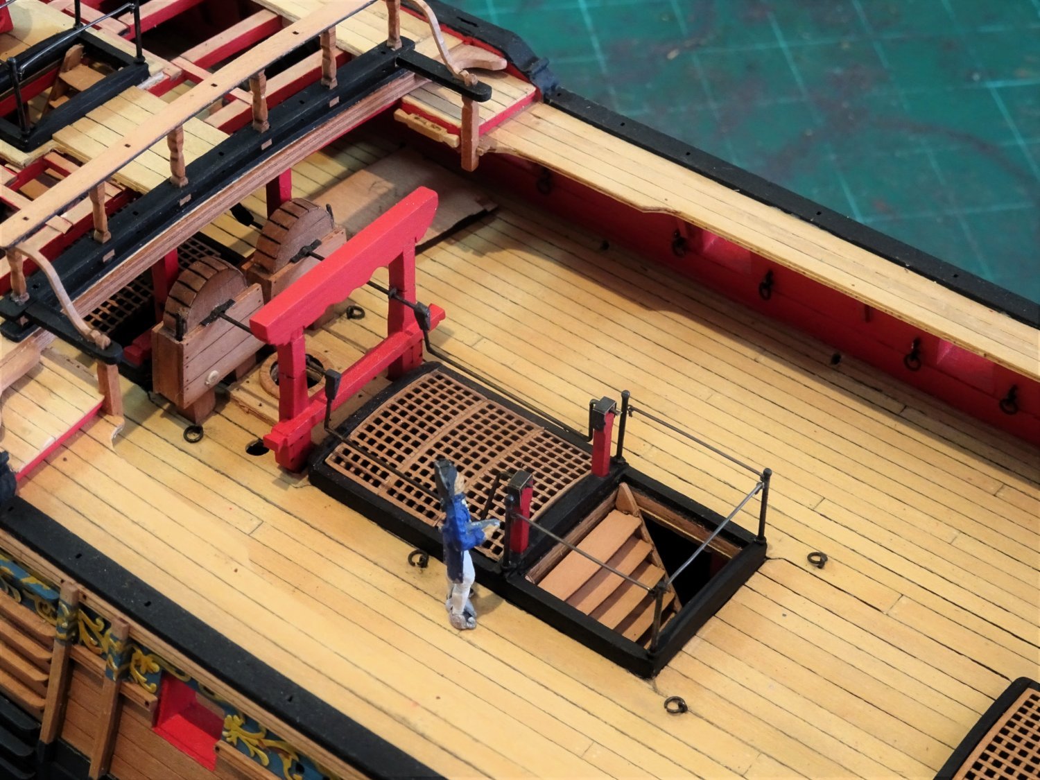
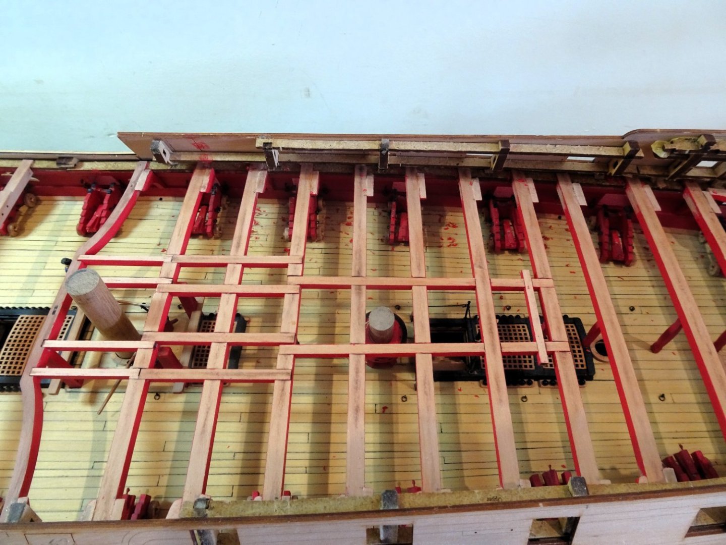
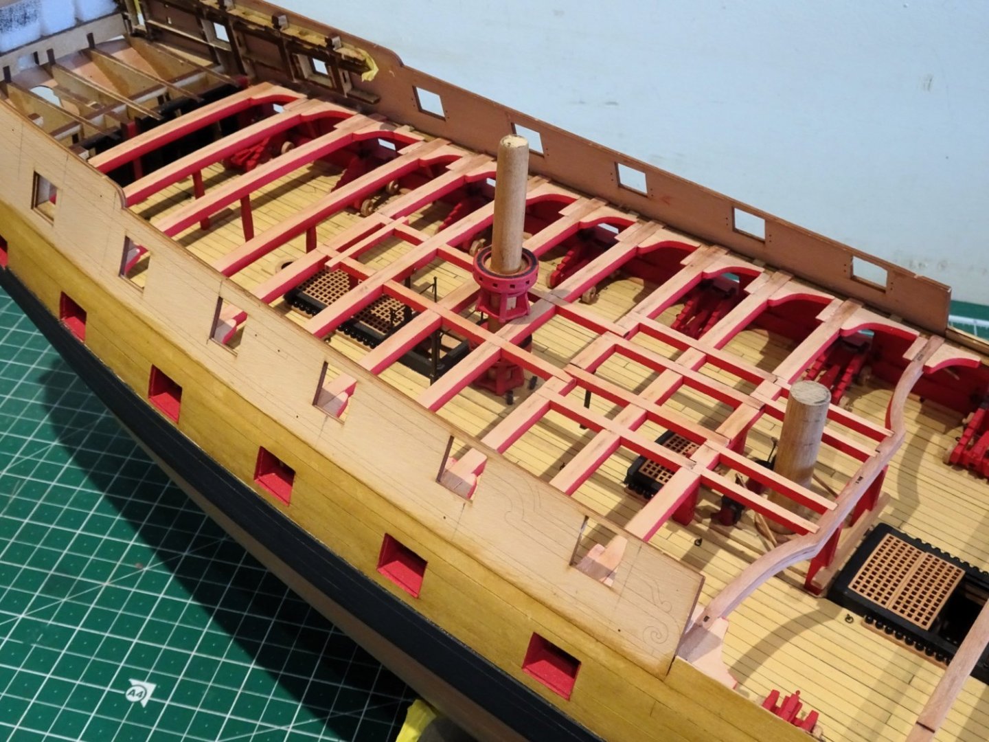
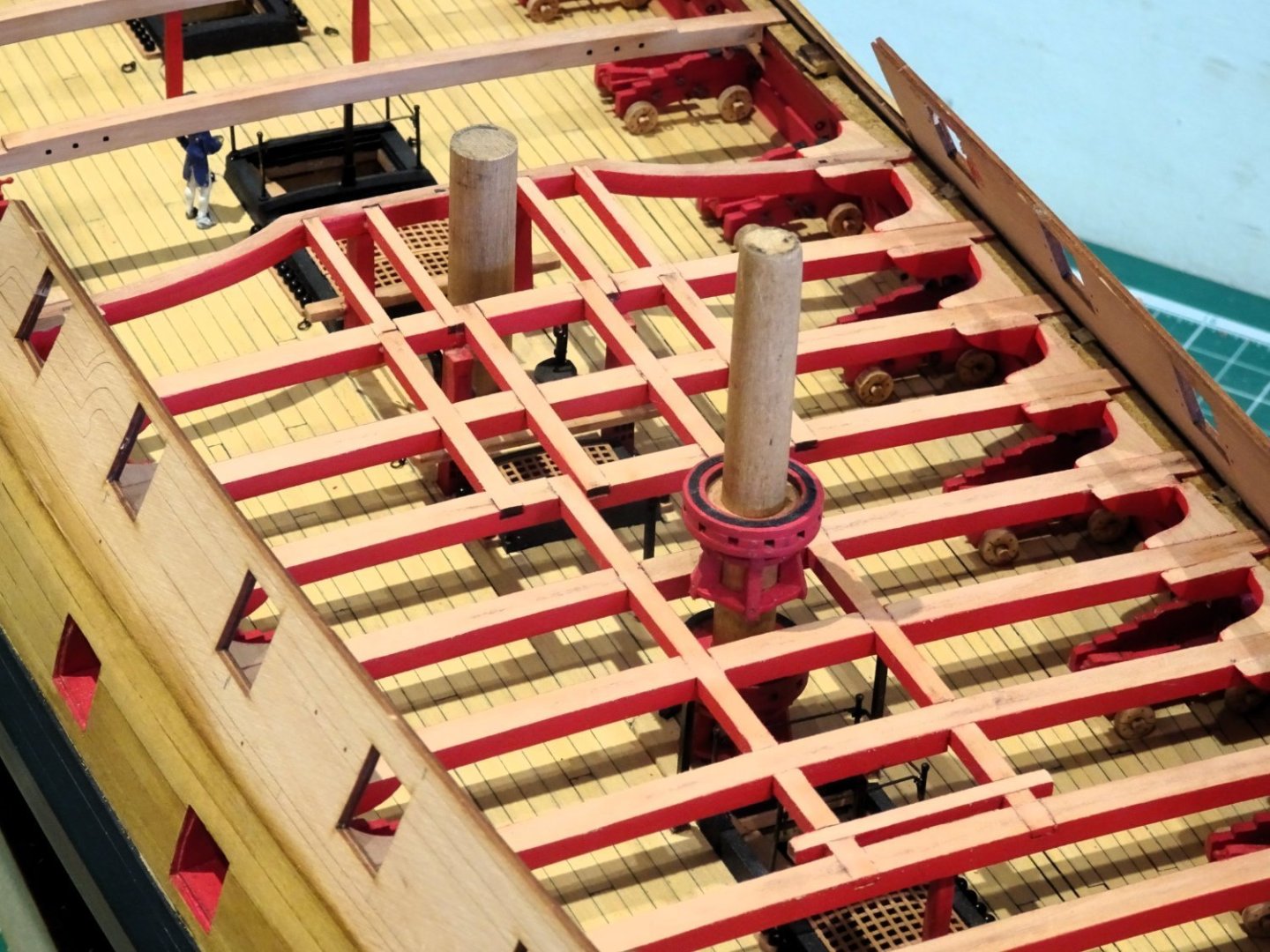
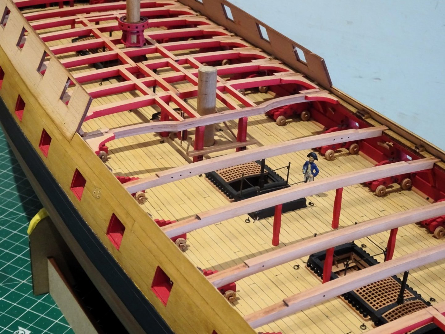
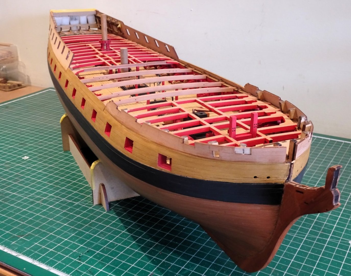
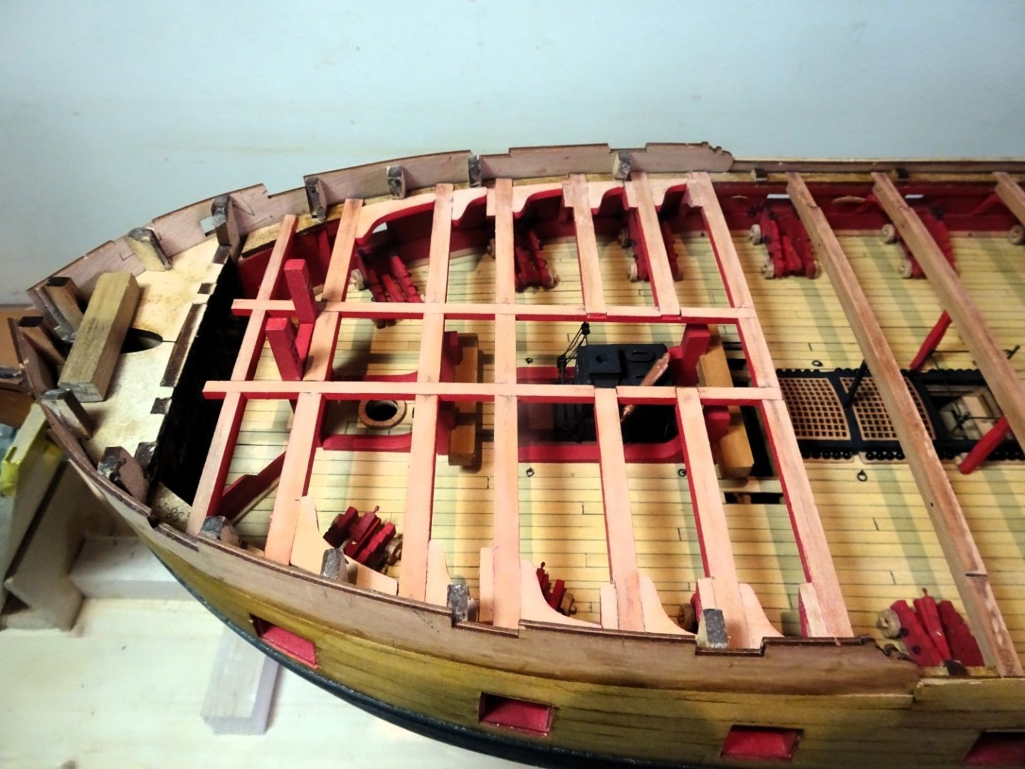
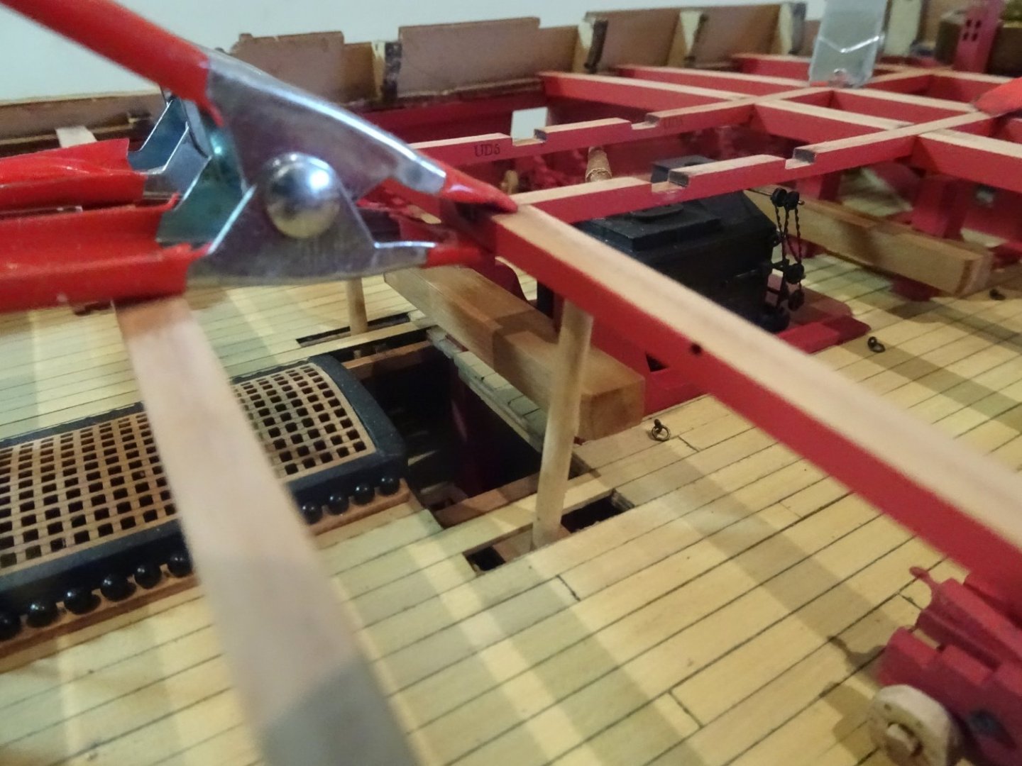
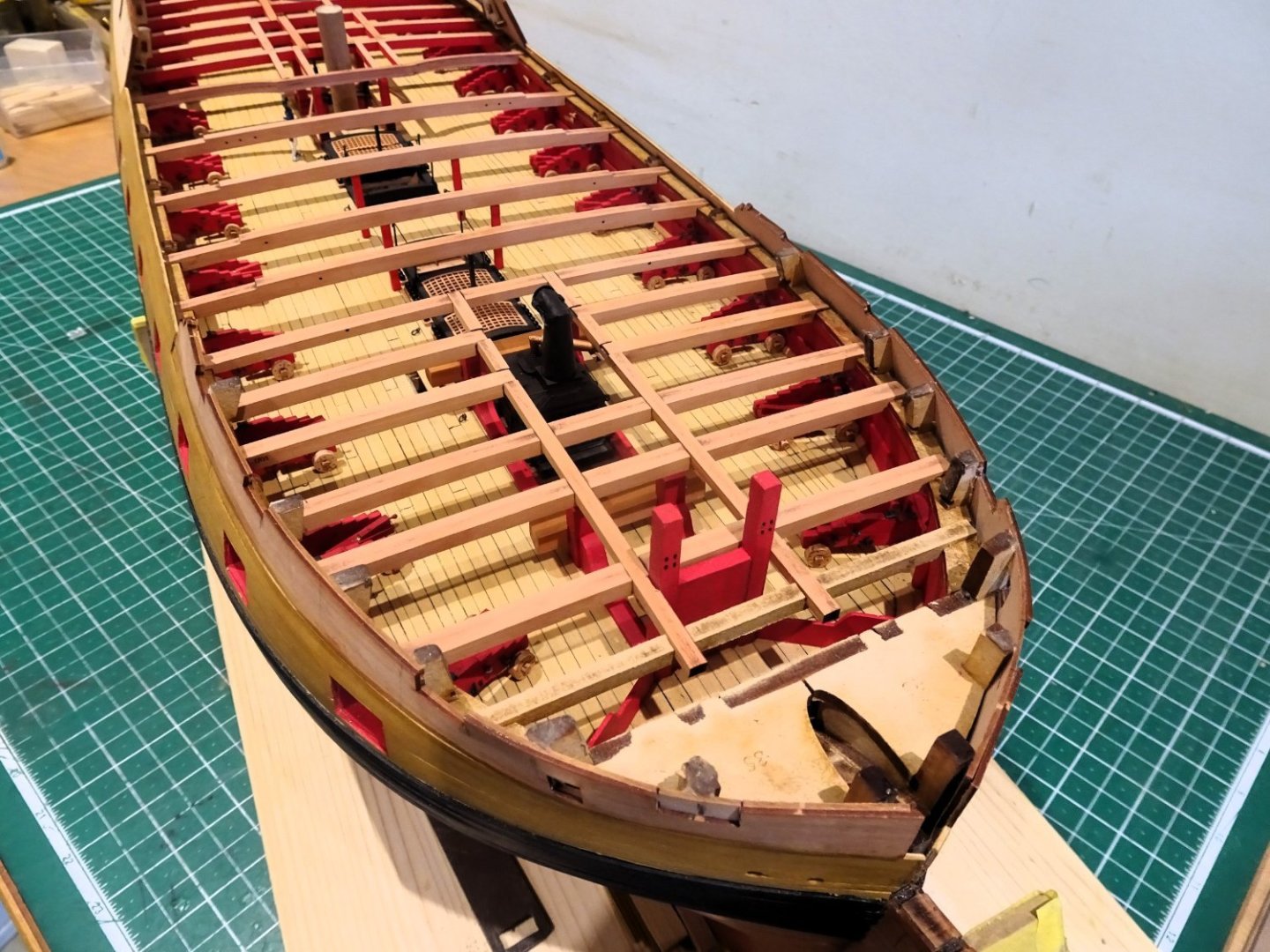
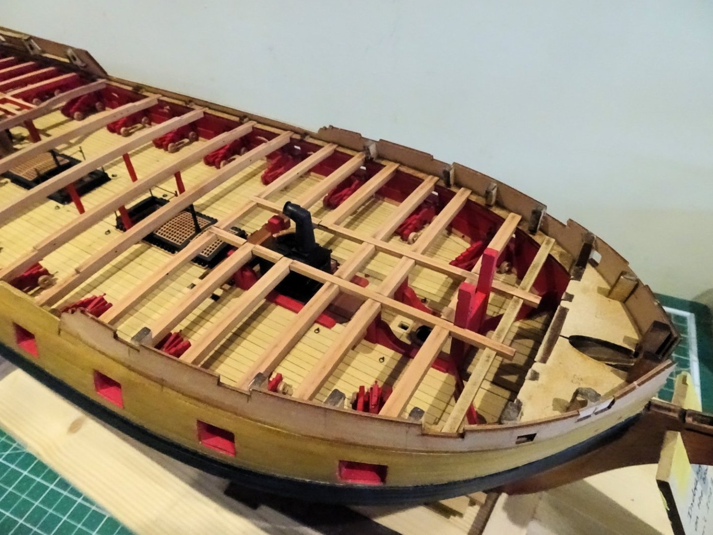
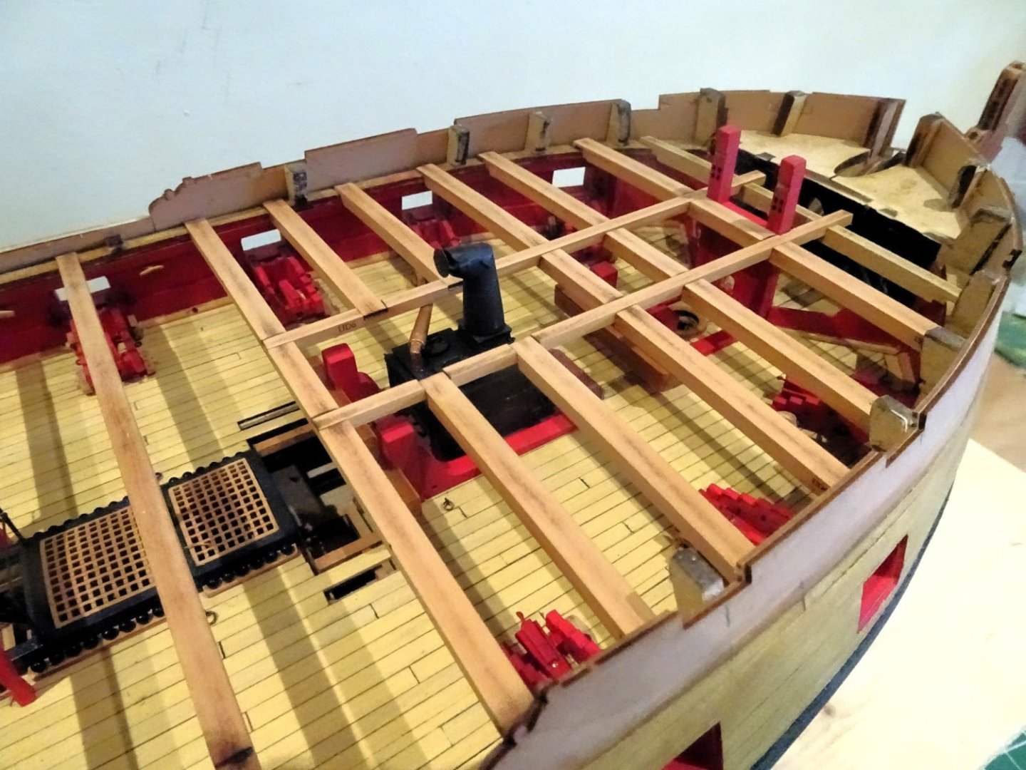
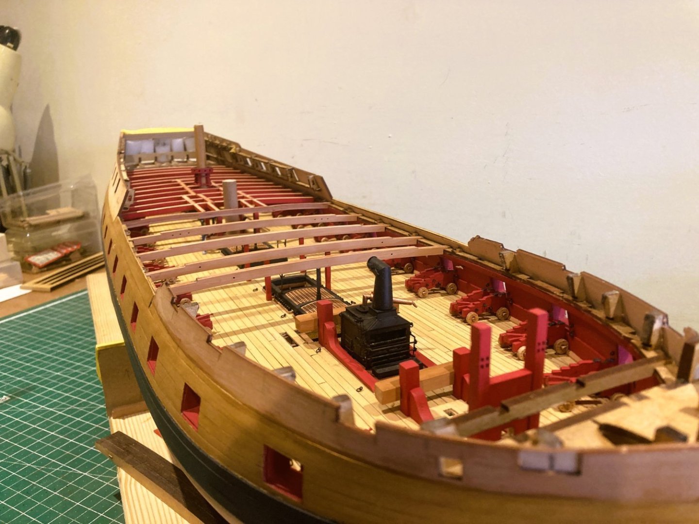
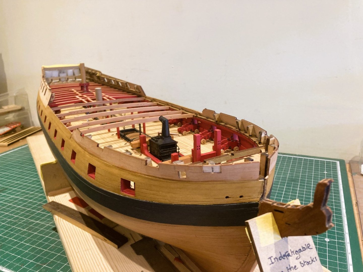
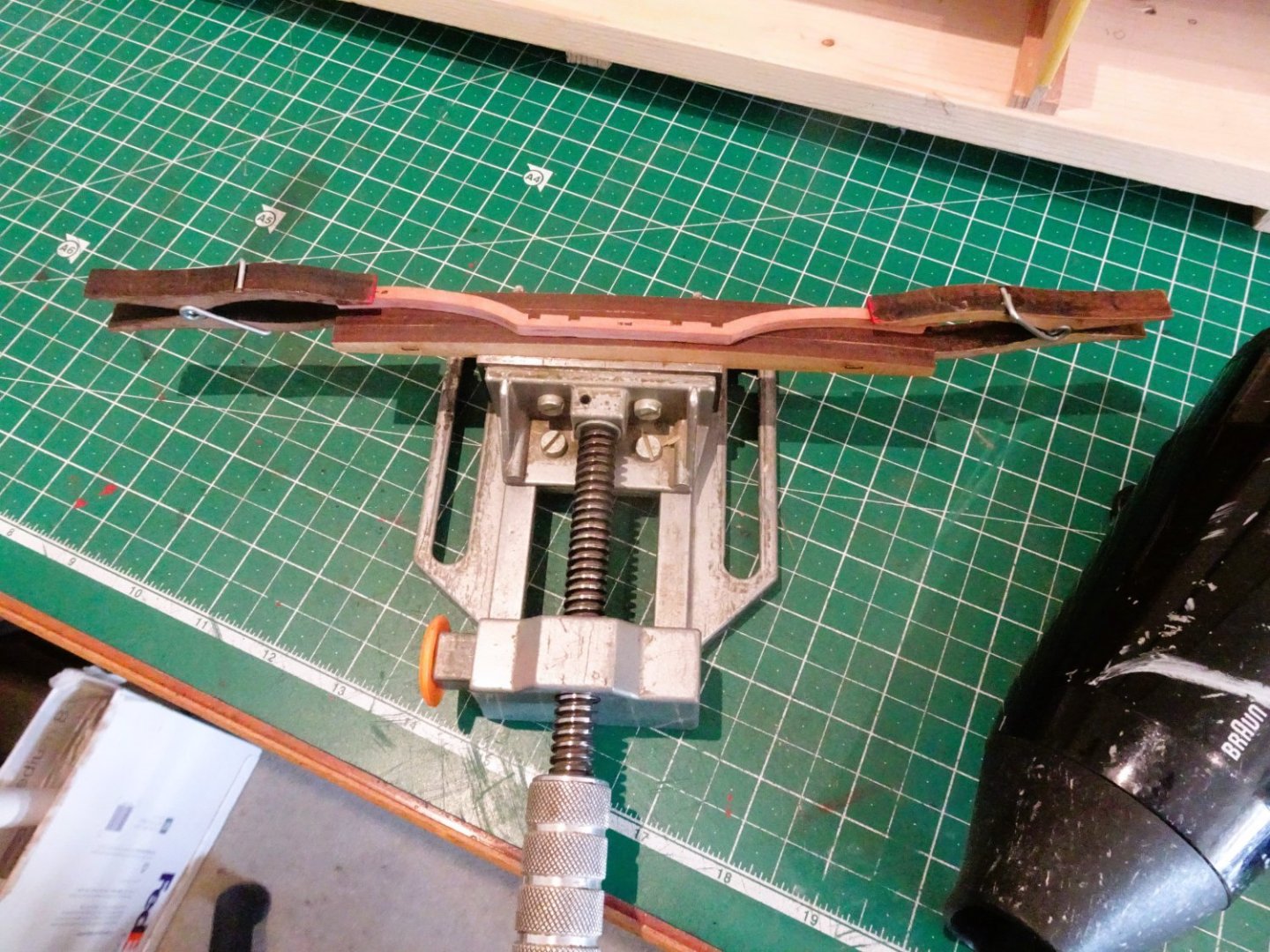
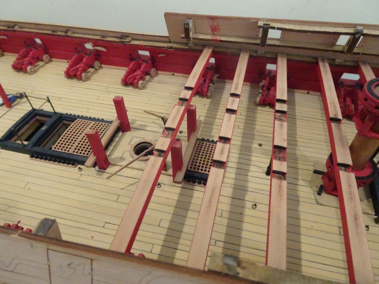
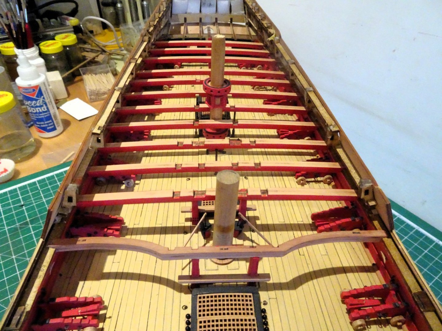
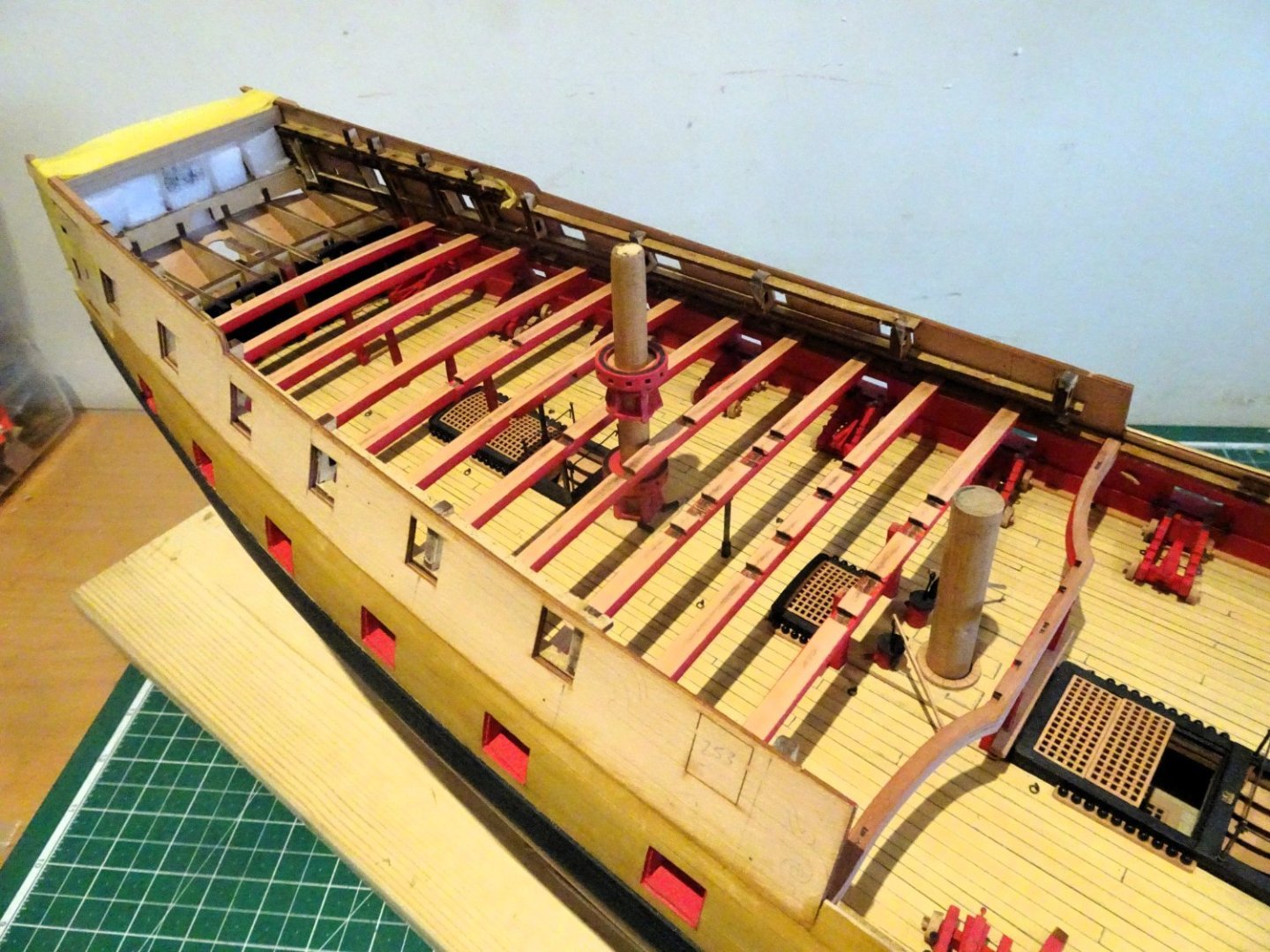
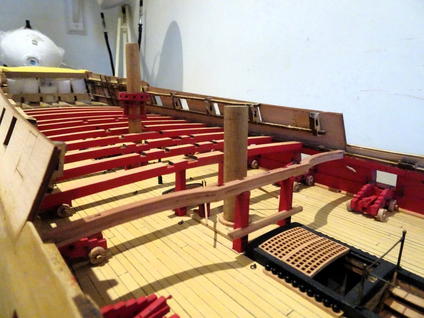
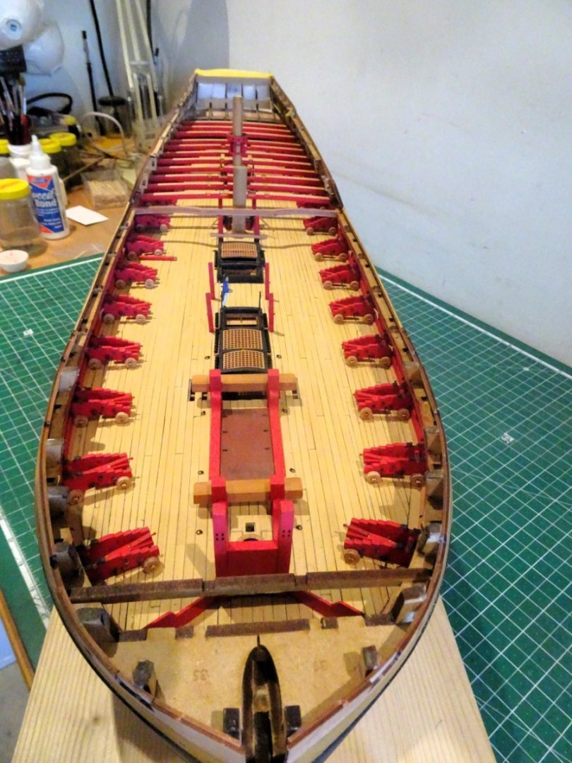
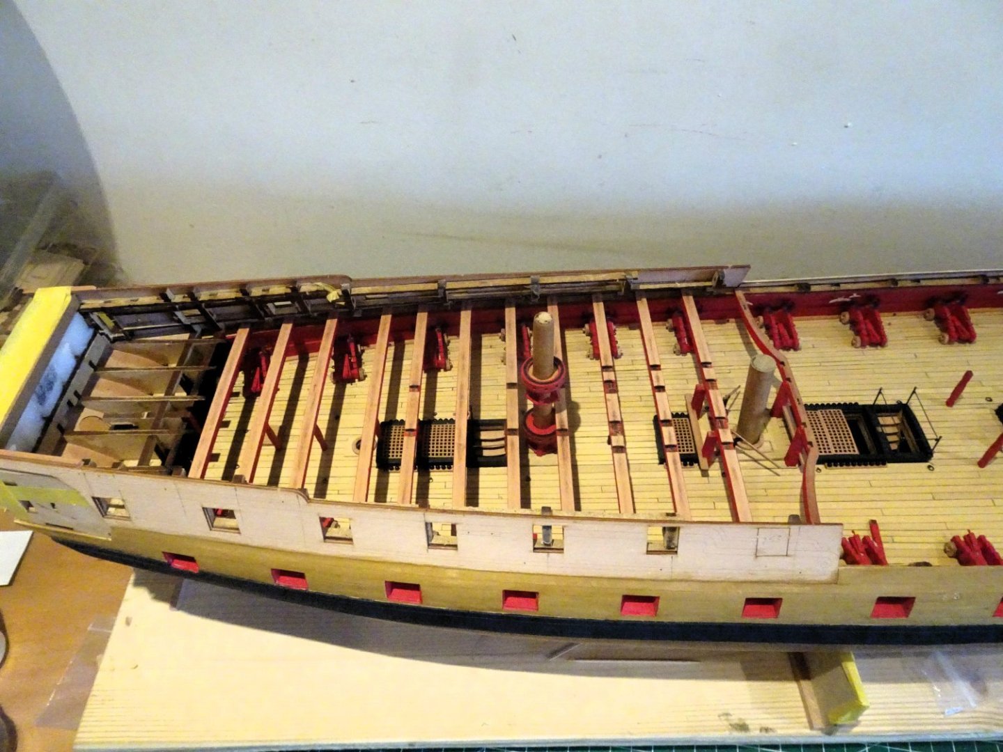
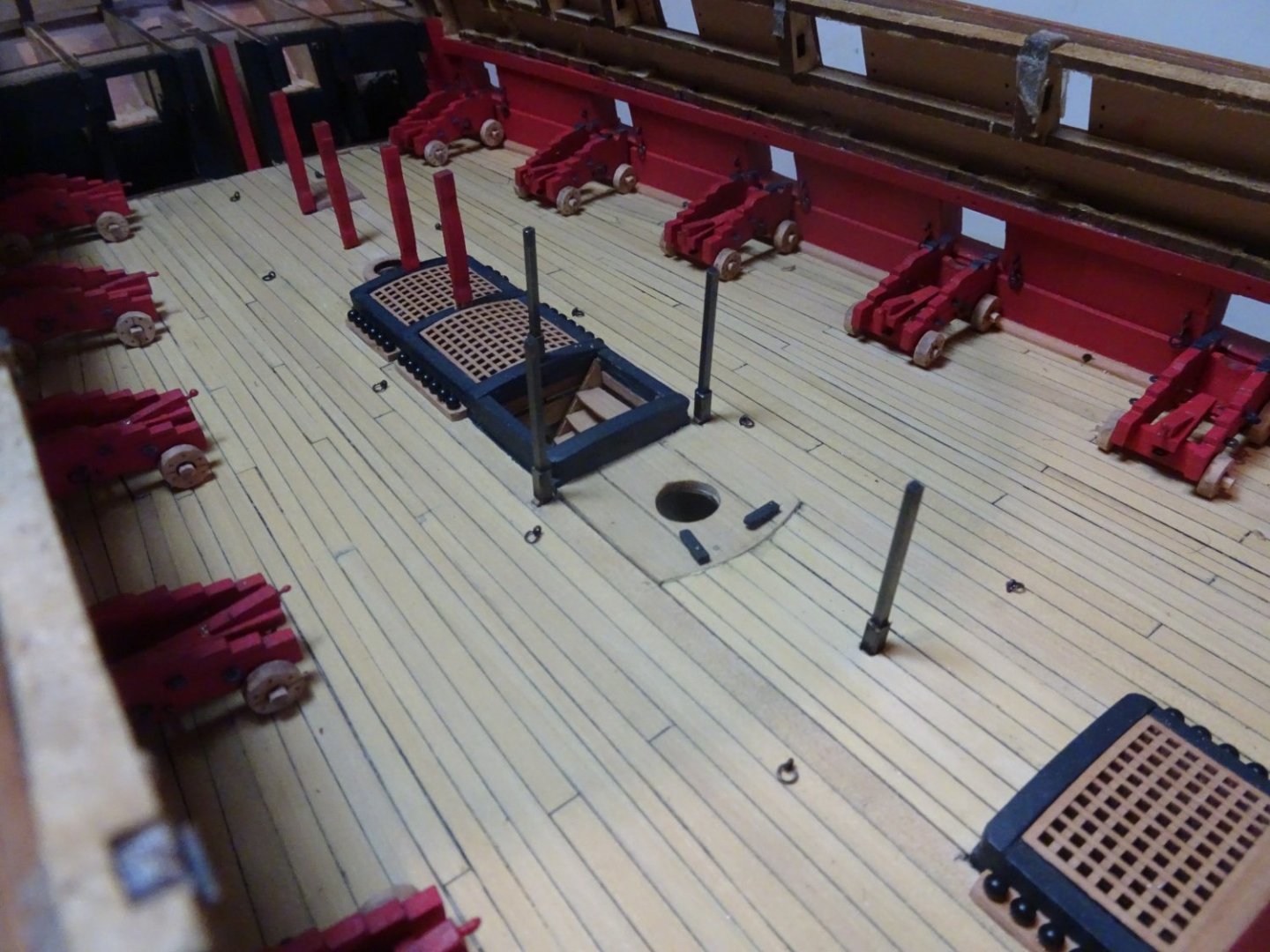
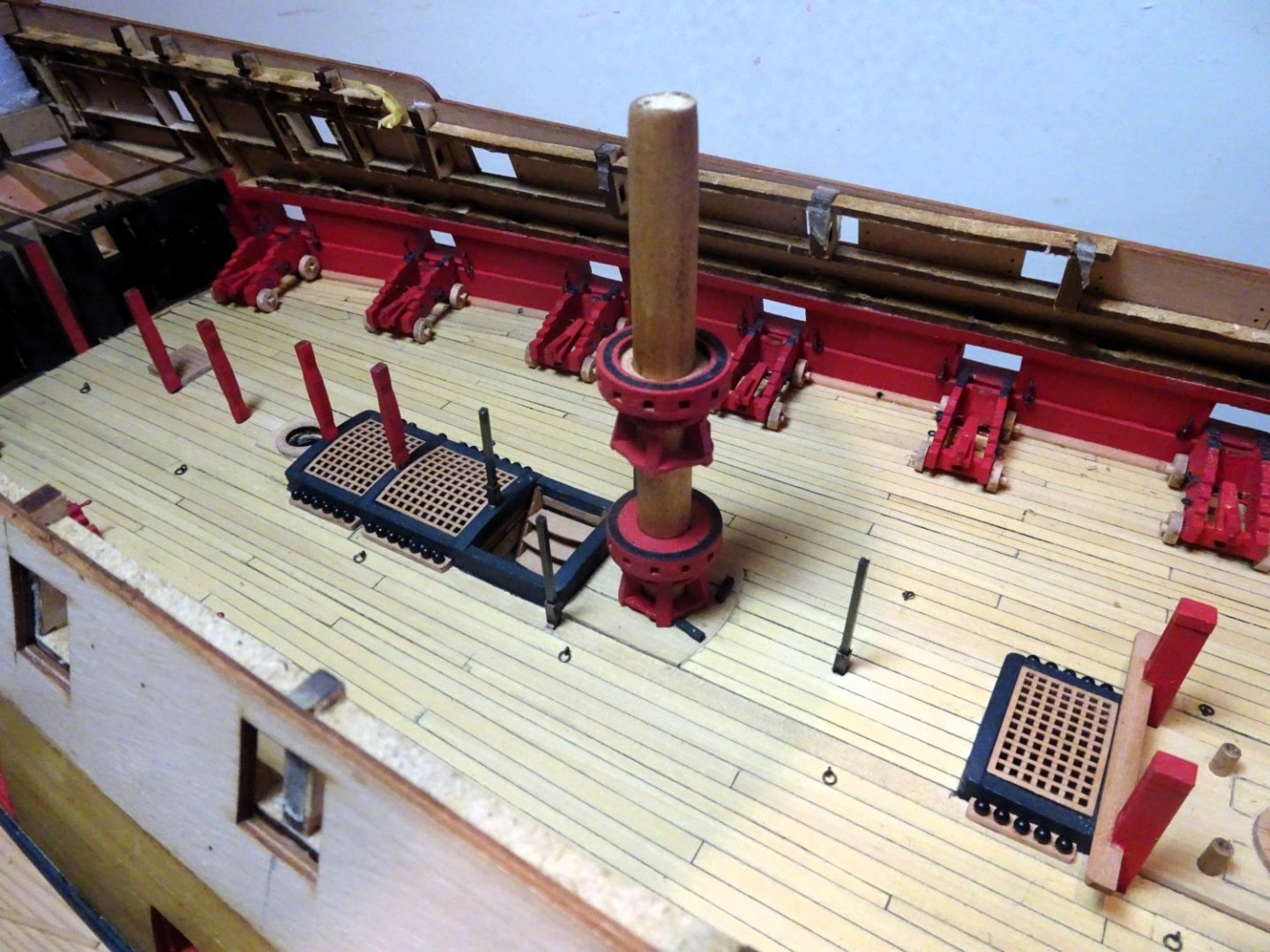
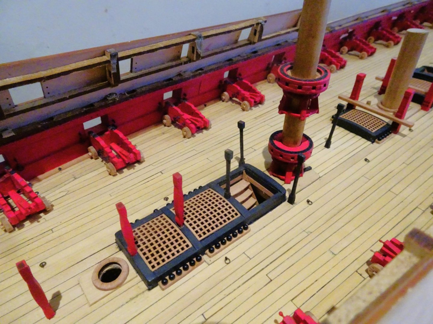
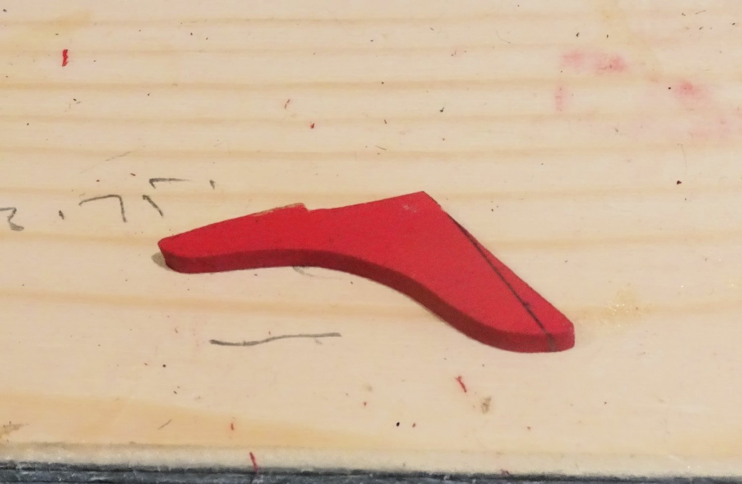
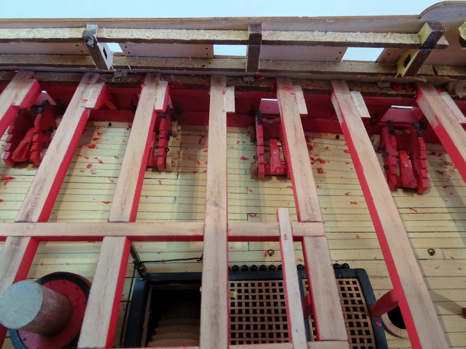
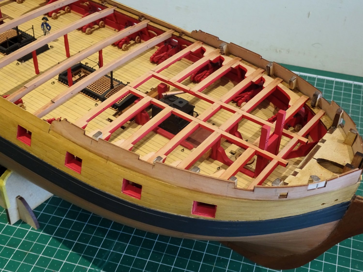
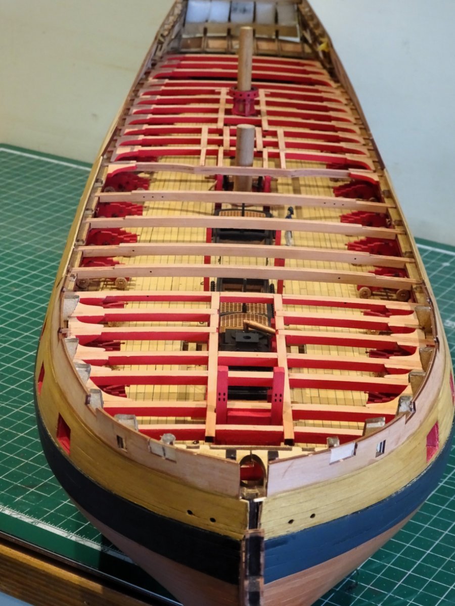
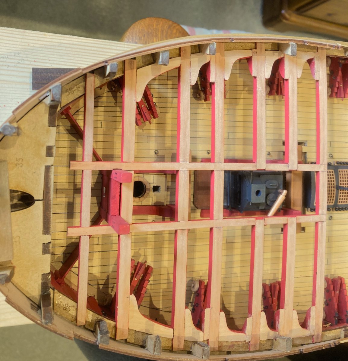
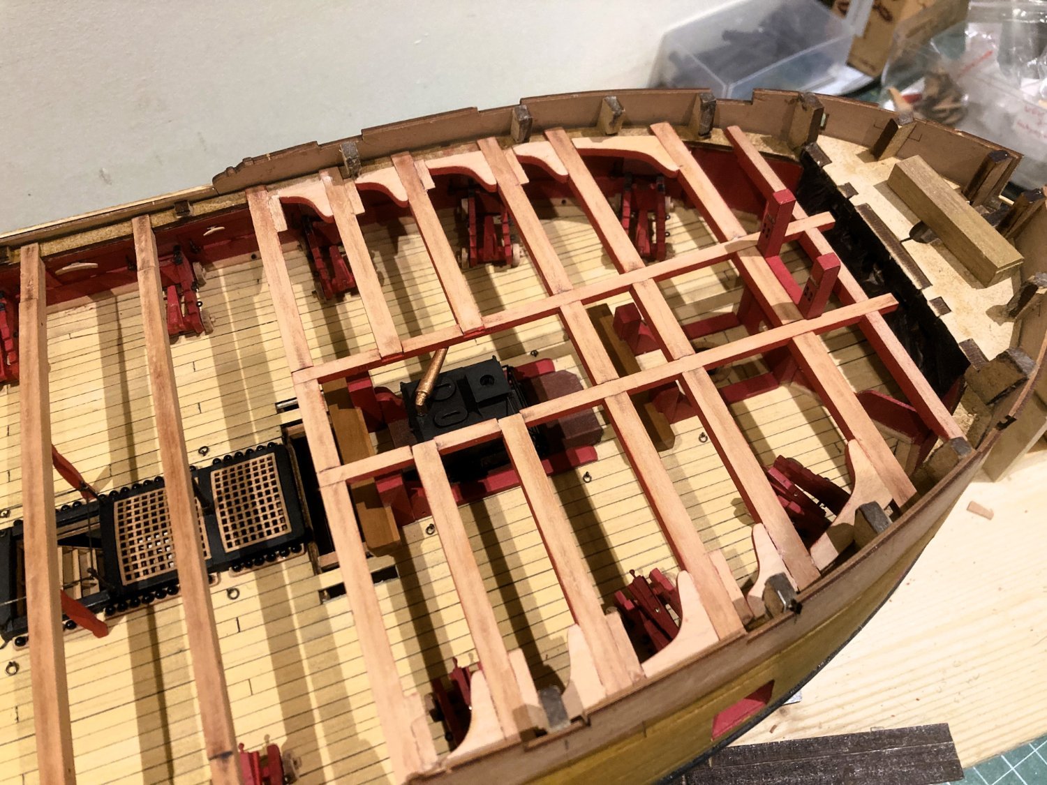
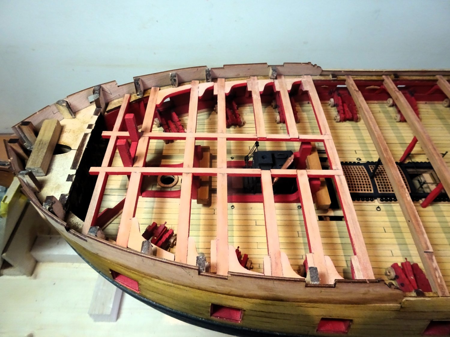
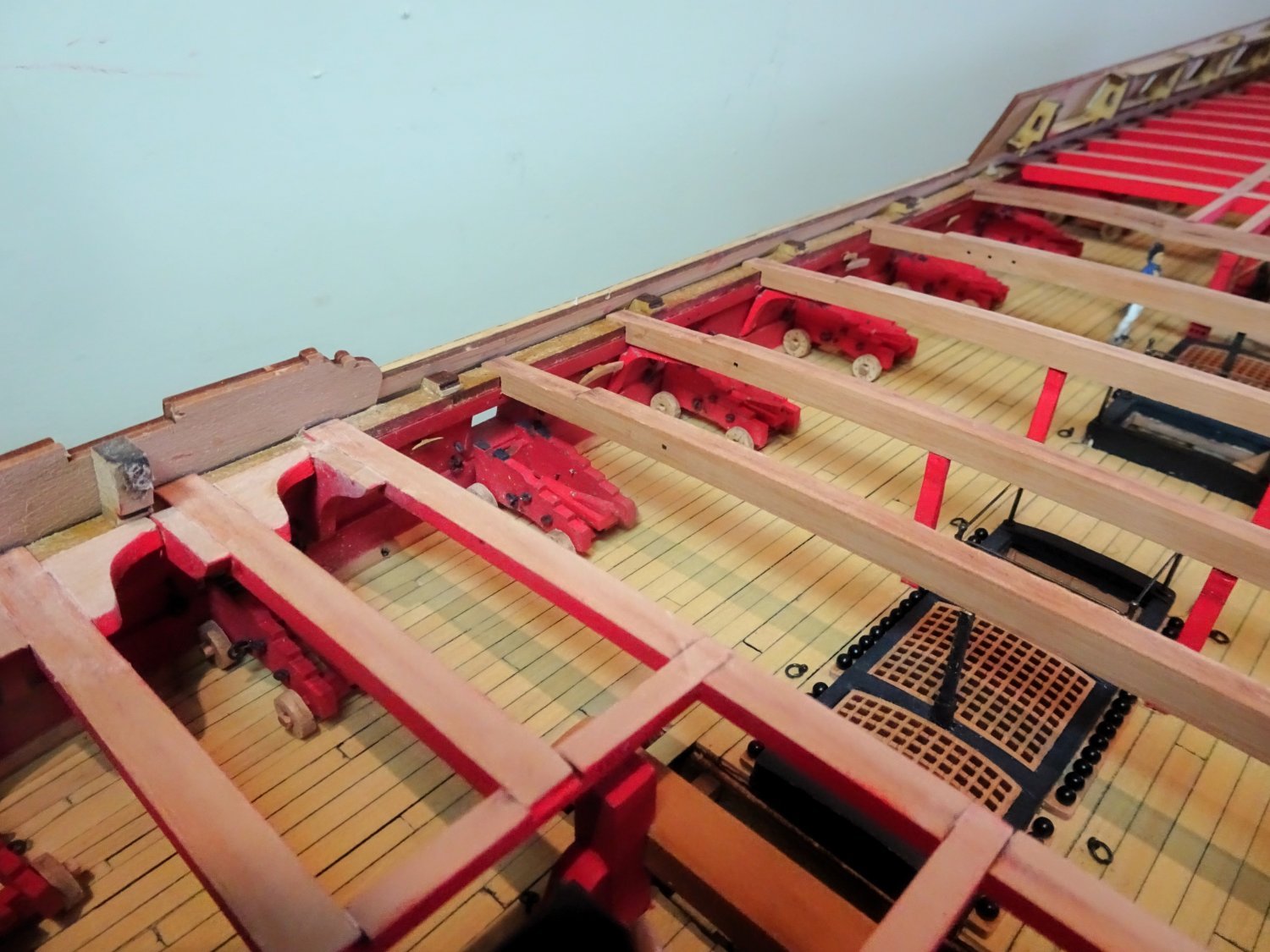
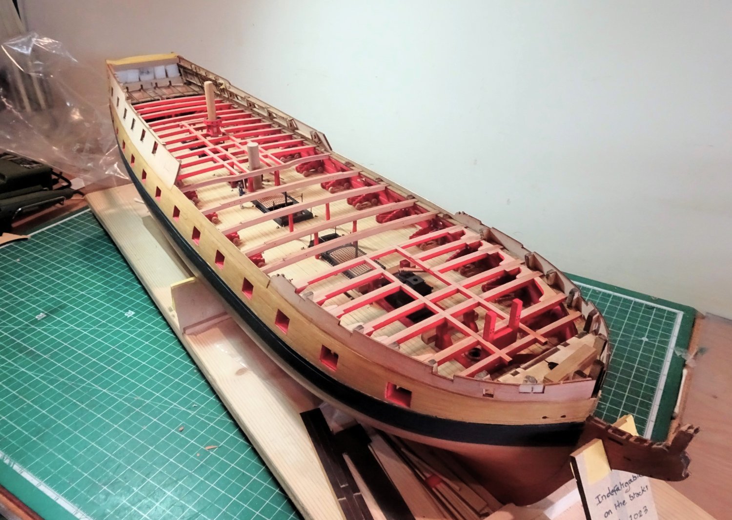
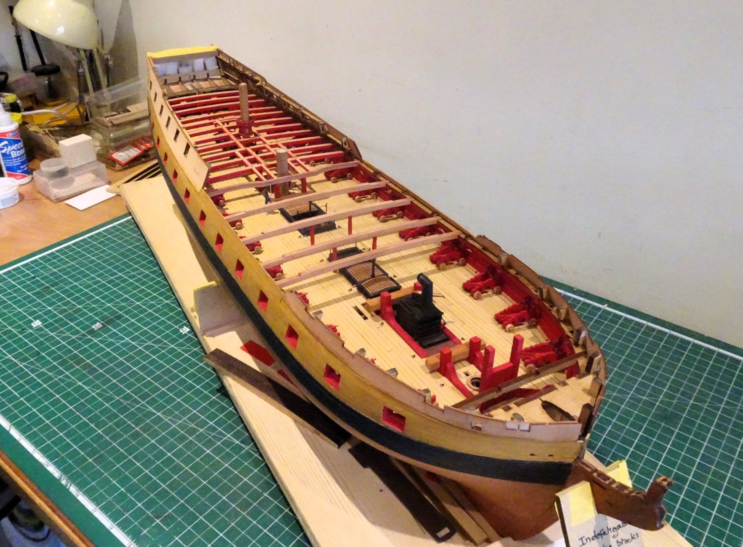
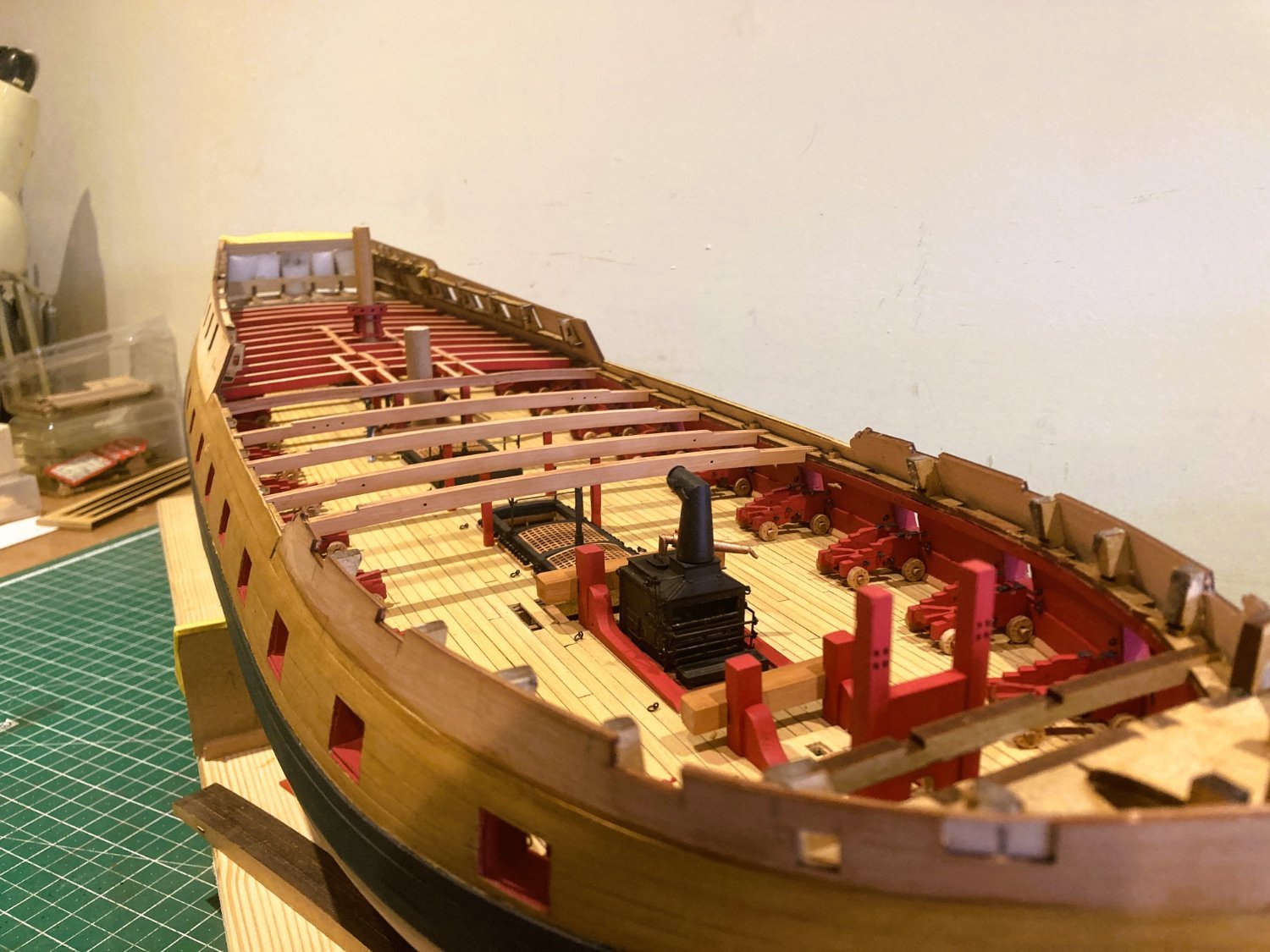
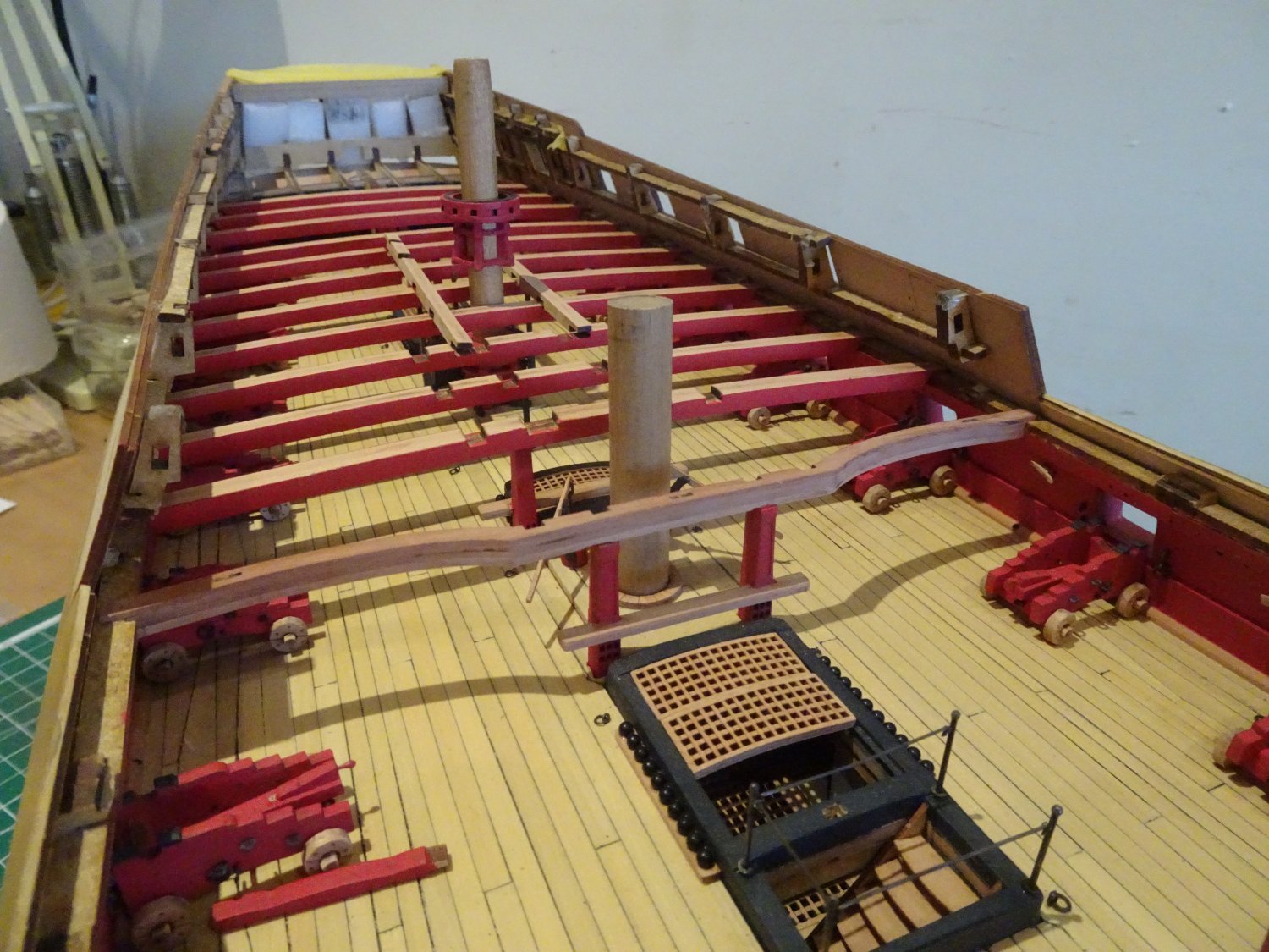
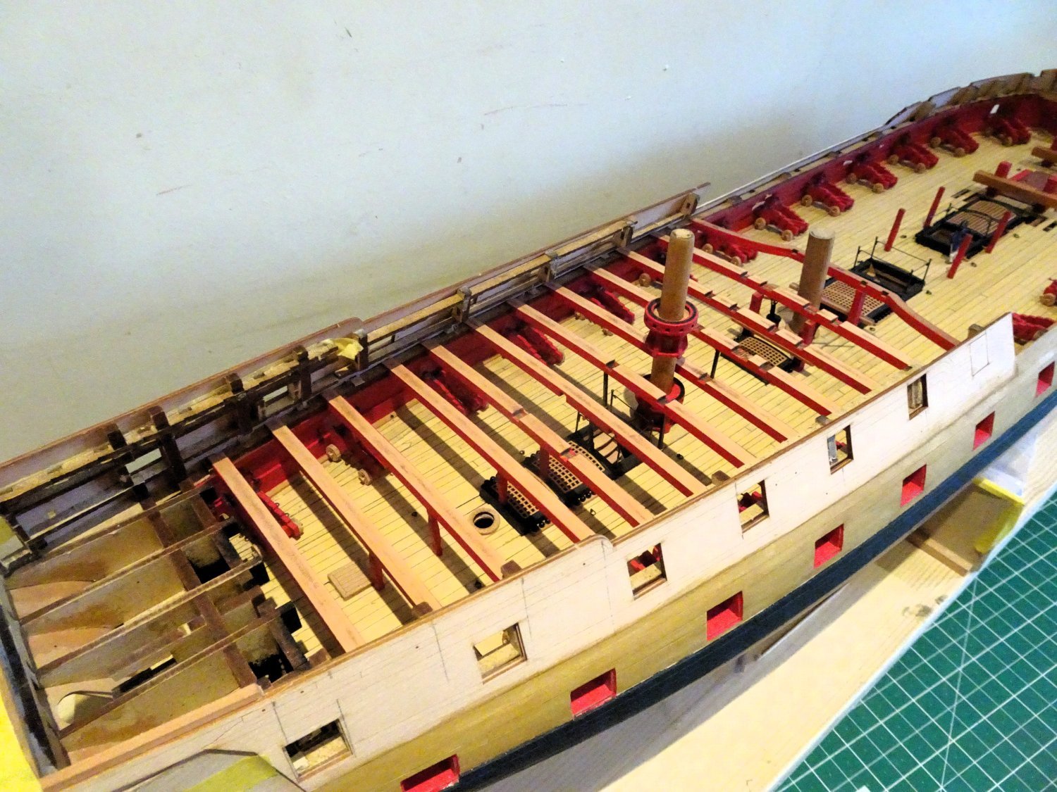
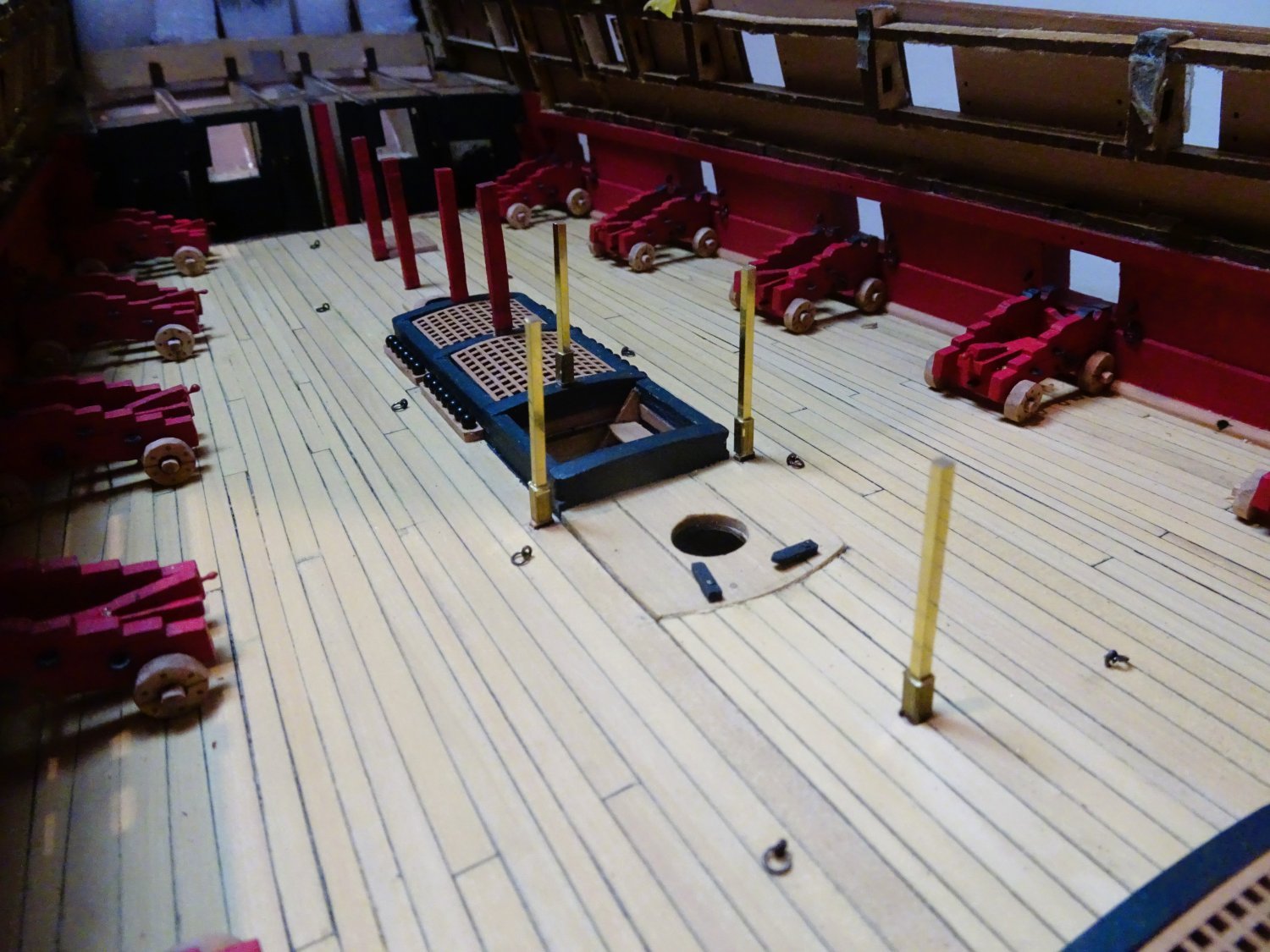
 Post Eight-one Quarterdeck knees Prepping the knees didn’t take that long, but it helps to have a system. 2088 2098 Fitting these parts does mess up the painted bulwarks, fortunately there is plenty of room for cleaning up. Were I doing this job again I would have left the area of the beams covered by the knees unpainted before fitting, also the sides of the hanging knees where they attach to beam and Lodging knees. Easier to touch in the paintwork rather than scrape away, and then have to clean up and re-touch anyway. This time I fitted the full hanging knees first, followed by the short versions, and then the Lodging knees. 2092 This photo shows the trimming necessary to allow the knee to sit flush with the beam camber. The rebate on the back edge was lengthened a little to allow the knee to meet the beam camber at the deck clamps. 2099 I had imagined that fitting the Qtr deck Hanging knees would be trickier than those of the Foc’sle due to the tumblehome of the topsides. Surprisingly I found the opposite, but perhaps my experience with the Foc’sle improved my dexterity. 2114 As with the Foc’sle the Lodging knees presented little issues. 2107 2118 I also added the hanging knees fitted below the Waist beams. Three should be fitted but the aftermost location is fouled by the large cleat to take the Fore sheets.🤔 2106 The Foc’sle beams were given a clean up. 2109 2115 2119 Onto the deck layout. B.E. 22/09/2023
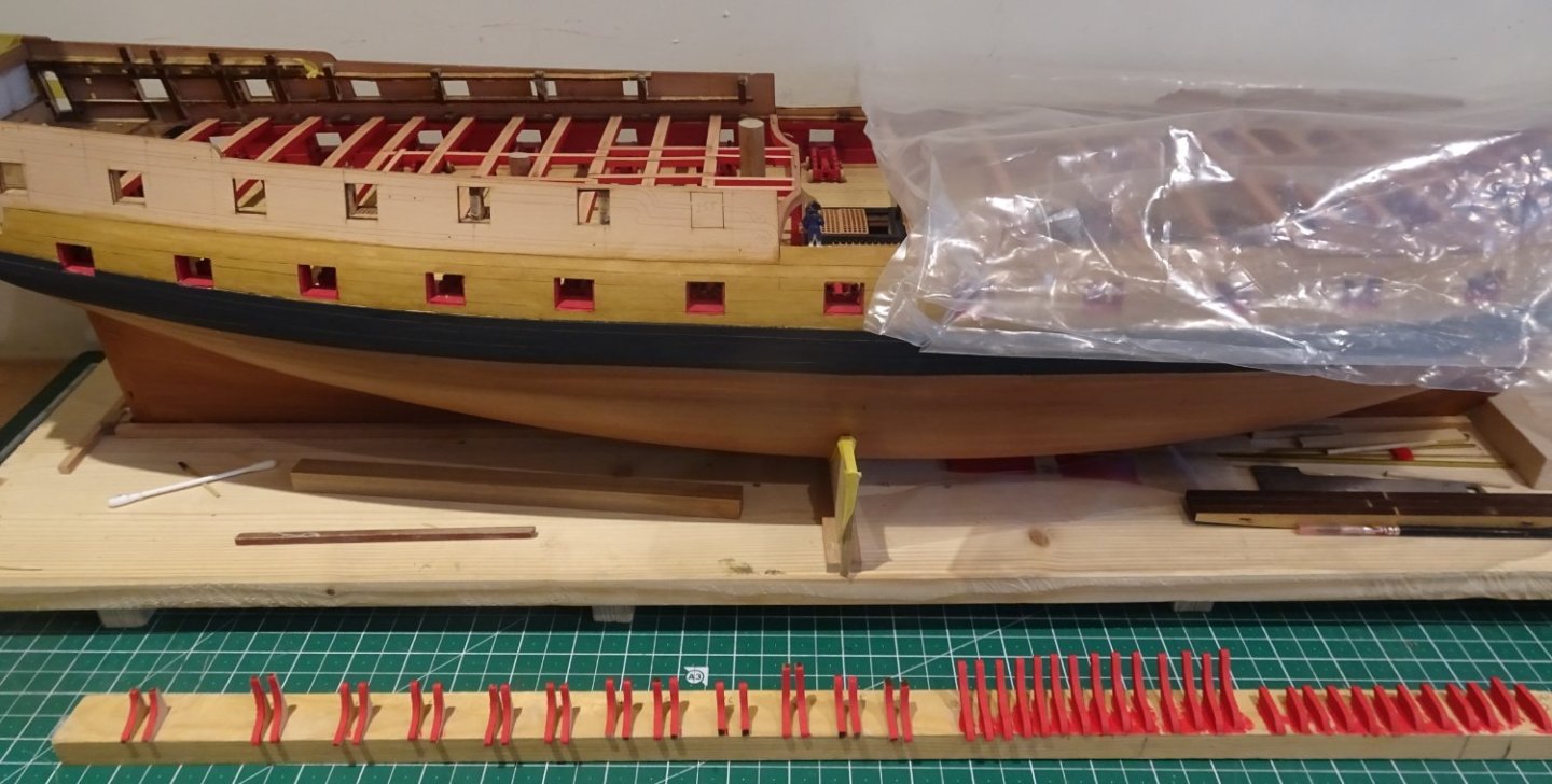


- 648 replies
-
- 19
-

-
- Indefatigable
- Vanguard Models
- (and 1 more)
-
I'm on the cusp now of working out the Foc'sle and Qtr deck planking patterns to best advantage, and I'm curious myself how that will turn out. B.E.
- 648 replies
-
- 4
-
-
- Indefatigable
- Vanguard Models
- (and 1 more)
-
Well done Mark on producing a fine looking model, I like the look of her. This kit is not the easiest to deal with, and bluff bowed ships, not the easiest to plank. ps that's a very nice mouse you produced, great weave effect.👍 B.E.
-
Nice work Mugje, your bow fairing looks very good. 👍 B.E.
-
Looking magnificent Yves, I do like the frieze work on the topsides👍 B.E.
-
I think they were used on the Foc'sle to frame the area around the central openings for the steam gratings / chimney, but I agree they did not seem to feature on the Quarterdeck framing due to the less weight borne by that deck, compared to the Upper deck. B.E.
- 648 replies
-
- 2
-
-
- Indefatigable
- Vanguard Models
- (and 1 more)
-
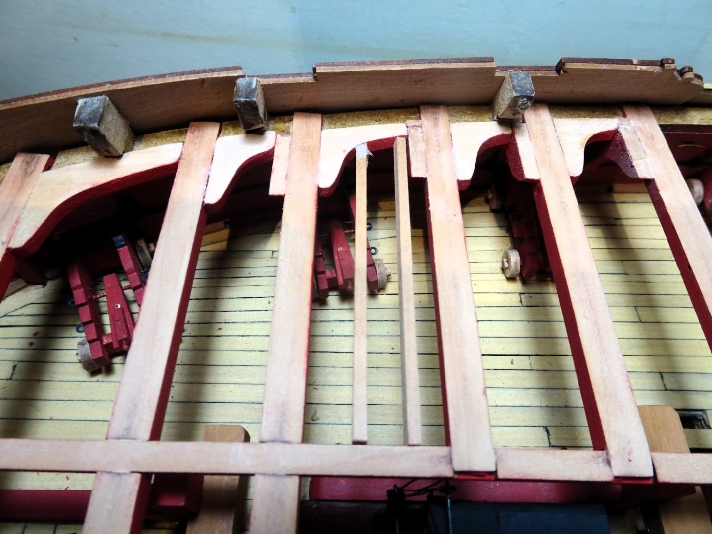
Thankyou Mugje and Theo. @ Theo - Deck ledges are narrower timbers that run between the carlings athwartships. 2095 2094 These pics show a mock up of how they were fitted. In reality they were let into the carlings, but ran flush with the deck beam cambers. B.E.
- 648 replies
-
- 16
-
-
- Indefatigable
- Vanguard Models
- (and 1 more)
-
Hi Tony, I use equal amounts of varnish and white spirit mixed together. Wipe it on, and immediately wipe it off for initial protection, apply further coats for a deeper colour. B.E.
-
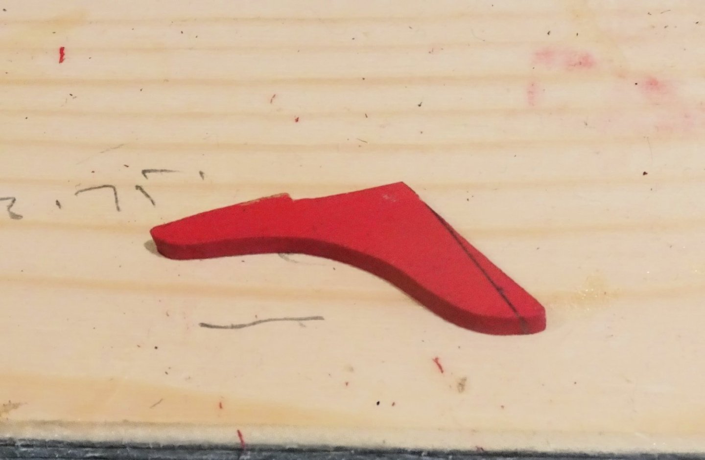
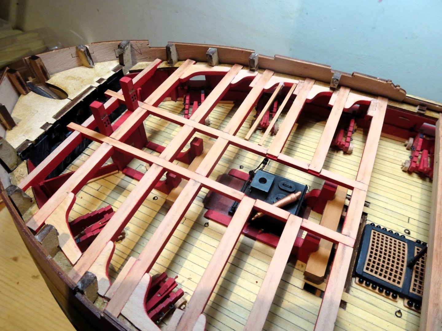
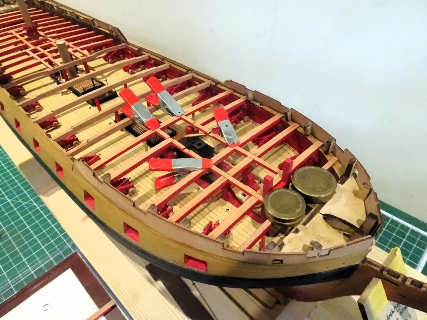
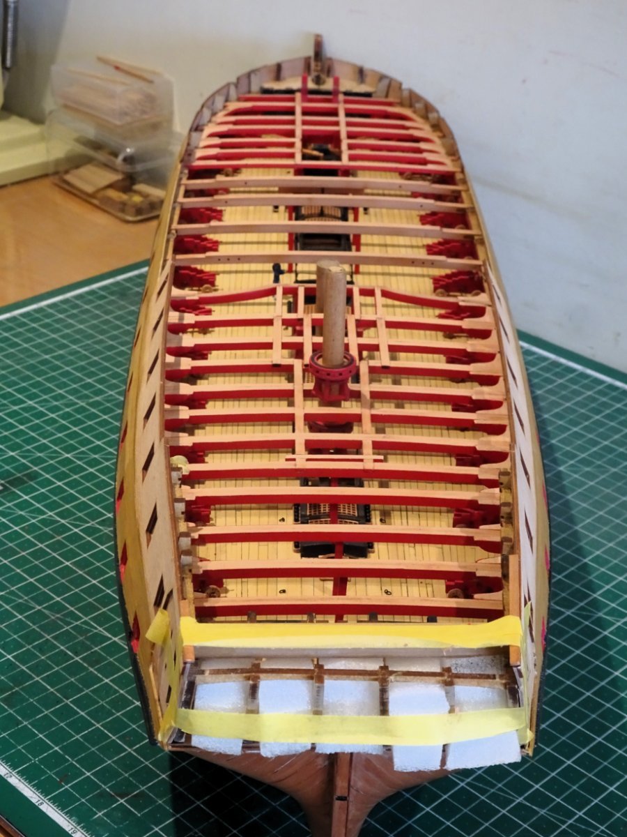
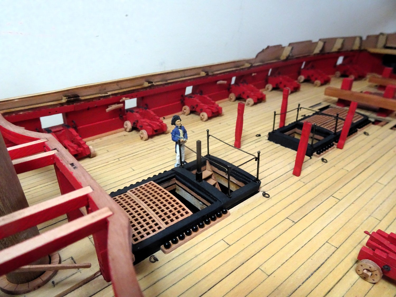
Post Eighty Knees Three full days’ work sees the completion of the Fo’csle deck framing. There are four styles of knees used on the foc’sle and waist, many of them location specific. Each needs cleaning and painting prior to use, and I found a sanding band/ mandrel made quick work of removing heavy char from these small fittings. I used a Proxxon 60/EF drill for the purpose, but any other similar tool (Dremel) would serve equally well. Once cleaned and painted, Plan sheet 4 gives the location for fitting, and I’m good to go. The phrase ‘good to go’ belies the very fiddly process of fitting these knees. 1369 I start at the Bow and once the fore-most Lodging knees are fitted the fun begins. 1368 I attend to the Hanging knees first, some of these are referred to as ‘dummy’ and are a fore shortened version to avoid fouling gun-ports. I fitted these first. 2080 As I expected fitting proved tricky, the full-length knees even more problematical, getting the vertical arm and horizontal knee to match the deck beam and quickworks was a tad trying to say the least. 2081 I found it necessary to adjust the angle of the knee where it joins the deck beam. I took the approach of fitting the bulwark part and then trimming the knee angle to lie flush with the deck beam. 2079 The remaining Lodging knees which proved far less trouble, fitted neatly between the beam and hanging knee. 1366 I am not adding the Ledges that fit between the carlings and knees as these would obscure a lot of the view, which would defeat my purpose. 1372 I think the addition of these fittings adds immensely to the look of a ‘Navy Board’ style model. 2083 The paintwork took a hit during fitting, but I will attend to this once the larger exercise of fitting the Qtr deck is completed. B.E. 20/09/2023


- 648 replies
-
- 20
-
-
- Indefatigable
- Vanguard Models
- (and 1 more)
-
Hi Dave, I think I thinned it to the consistency of skimmed milk and applied it quickly using a broad chisel brush. I too use silkspan, or modelspan as it is now called as it has good strength qualities. Use of a hairdryer once applied, eliminates any risk of puddling, but the beauty of Silk/modelspan is that it can be re-wetted multiple times, particularly useful for sail shaping on the model. B.E.
- 126 replies
-
- 2
-
-
- le superbe
- heller
- (and 2 more)
-
You're welcome, and thanks for looking in on my build, glad you found it of use. B.E.
- 858 replies
-
- 1
-
-
- Sphinx
- Vanguard Models
- (and 1 more)
-
Post Seventy-nine Foc’sle (Part 2) 2073 The Foc’sle beams are fixed into place. 2074 Temporary props are used to support the breast beam whilst the carlings set. 2070 2067 The foremost beam of the Foc’sle deck is an mdf version, originally designed to incorporate the Bowsprit step. To match the other beams, the top was faced with 0.6mm pear. With the beams now fixed I move onto the Hanging and lodging knees. This is a prep intensive exercise with char removal, painting, and fettlin’ to fit. Those opting to fully deck the model need have little concern for such detail, as it will all be covered, but I would probably have done them anyway, given that Chris has taken the trouble to provide them. B.E. 17/09/2023
- 648 replies
-
- 21
-
-
- Indefatigable
- Vanguard Models
- (and 1 more)
-
Post Seventy-eight Foc’sle More cleaning up of heavy char and a dry fit of the Foc’sle beams. 2056 2063 2064 2065 The beams and carlings slot easily into place, less trouble than the Qtr deck. Hopefully the Foc’sle breast beam will stiffen up once it is glued into place and the carlings added. Another round of painting now ensues, followed by the addition of hanging and lodging knees. Chris has kindly provided the lodging knees with the Indy kit, which saves me the tiresome task of making them as I did with the Sphinx build. Thanks Chris.👍 B.E. 16/09/2023

- 648 replies
-
- 19
-
-

-
- Indefatigable
- Vanguard Models
- (and 1 more)
-
A fine job on building the hull ECK, well done👍 B.E.
- 233 replies
-
- 1
-
-
- Indefatigable
- Vanguard Models
- (and 1 more)
-
Thank you Theo, A lot of praise should go to Chris whose designs and thoughtful build methods make us all look good, or at least better than we would otherwise. Chuck has a similar effect with his designs, and clear build processes. Even so, below that smooth surface, I’m churning water, and catch myself clenching my teeth working on the trickier bits. If I have a quality, it is a determination to slow down on a build and fight against the ‘that’ll do’ approach. I do strive to improve my builds, not always with full success, but I’m a lot harder on myself than I used to be. I see the same approach in your work. B. E.
- 648 replies
-
- 10
-
-
-
- Indefatigable
- Vanguard Models
- (and 1 more)
-
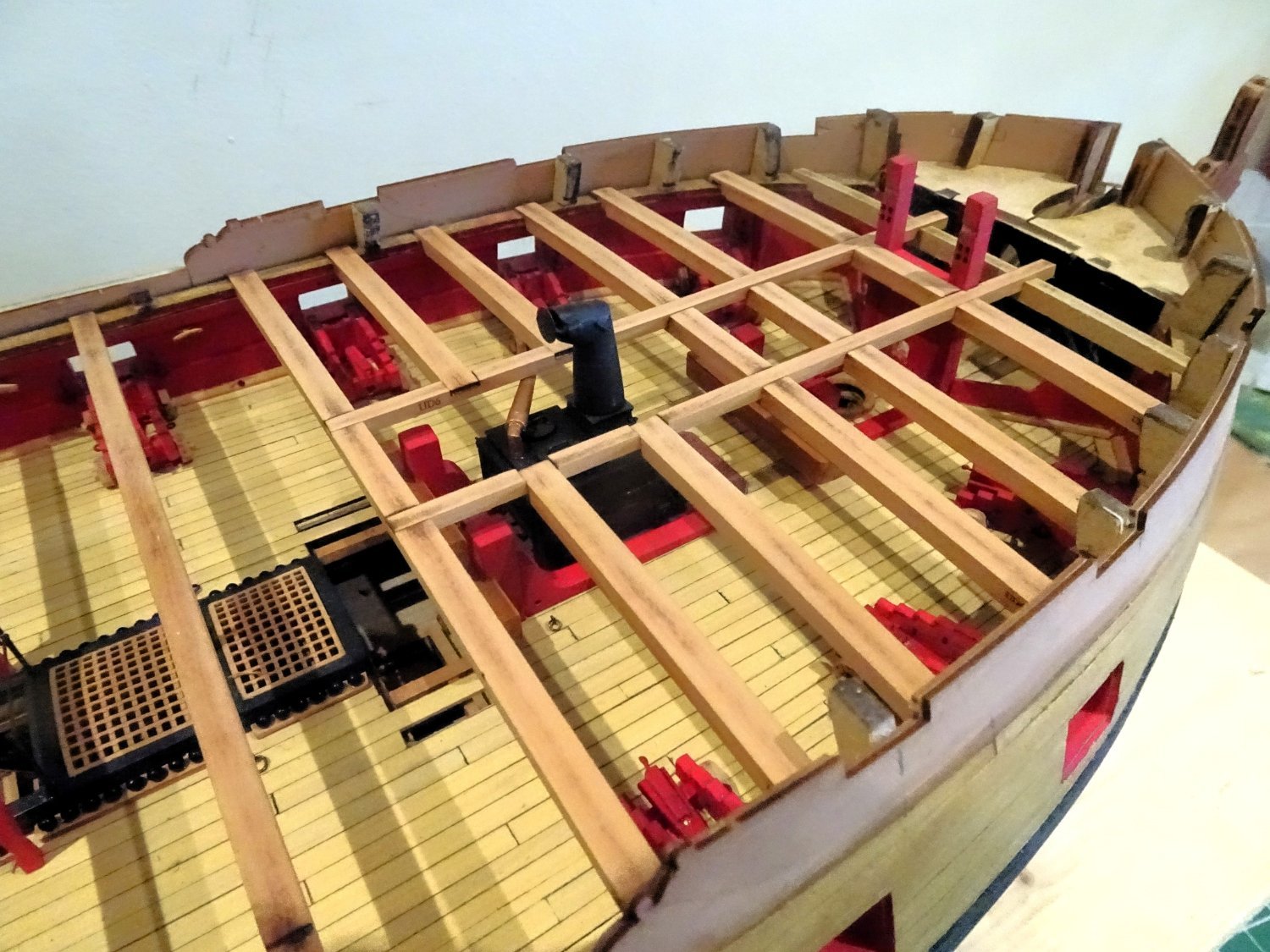
Post seventy-seven Waist Beams This section completes the framing over the waist. 1286 1285 2028 The beams slotted into place without issue. I’m glad I made the decision to replace the beam supports over the head ledges with ‘iron’ stanchions on my particular build. The shipyard is now closing for a week. Cheers, B.E. 08/09/2023.

- 648 replies
-
- 24
-
-
- Indefatigable
- Vanguard Models
- (and 1 more)
-
Thank you Ron, I hadn’t thought of that layout, I’ll be playing around with various options using card templates before I commit. I need to make up an example of the carronades and 12 pounder long to see how they impact on the deck space. As far as photo distortion is concerned, it’s not reflected on the actual model, so I’m not overly concerned. B.E.
- 648 replies
-
- 2
-
-
- Indefatigable
- Vanguard Models
- (and 1 more)
-
Thank you Mugje, the top faces still need a final clean as much of it will be left uncovered. The Lodging knees are yet to be fitted. The framing is much the same as on your Sphinx build, which I couldn't bear to cover up either. Cheers, B.E.
- 648 replies
-
- 2
-
-
- Indefatigable
- Vanguard Models
- (and 1 more)
-
Simply magnificent Marc, what a display of artistry👏 B.E.
- 2,444 replies
-
- 2
-
-
-
- heller
- soleil royal
- (and 9 more)
-
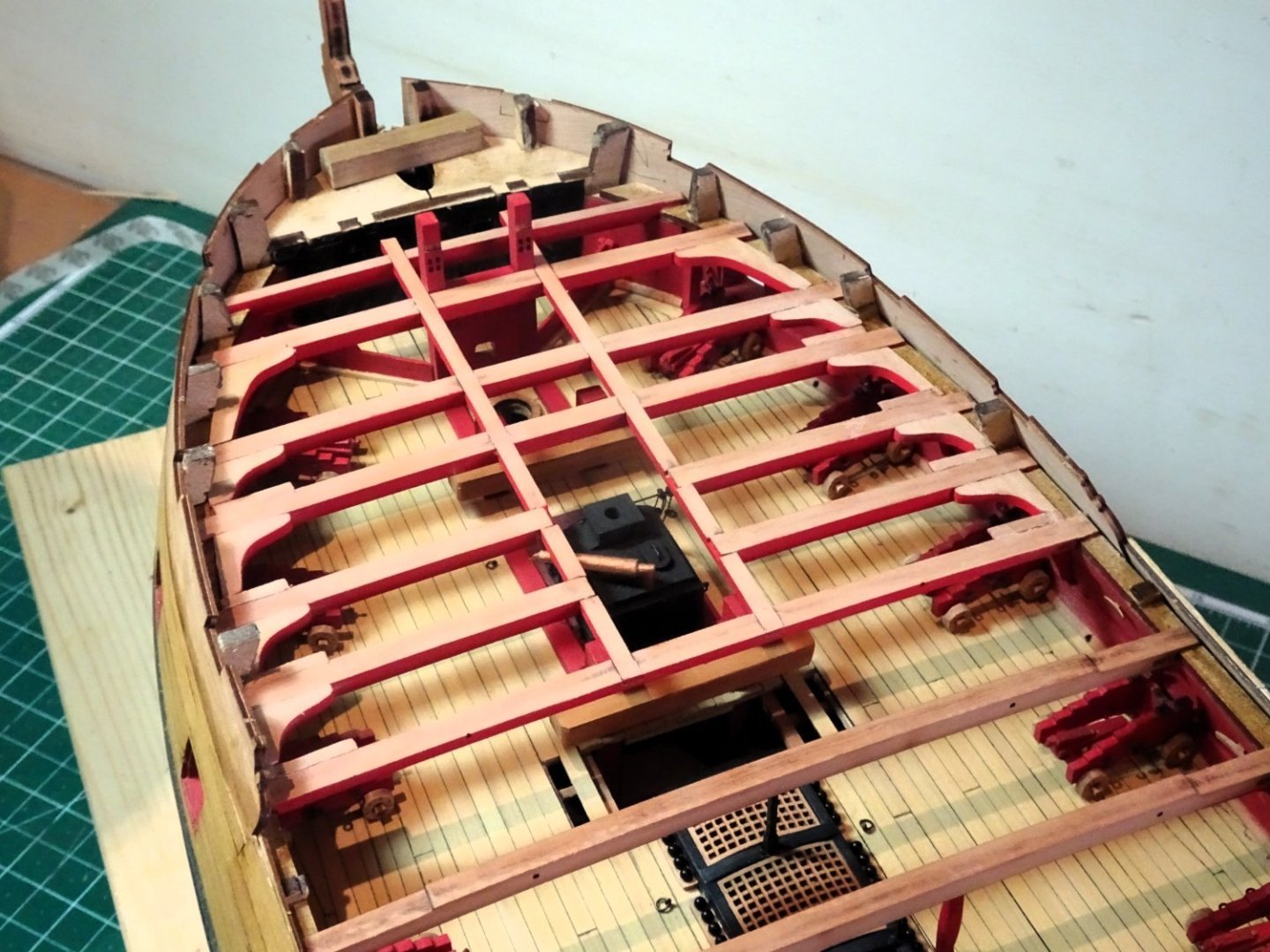
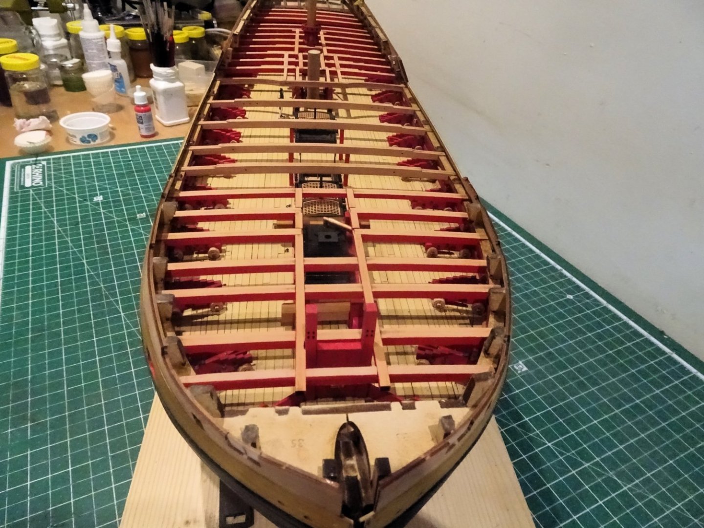
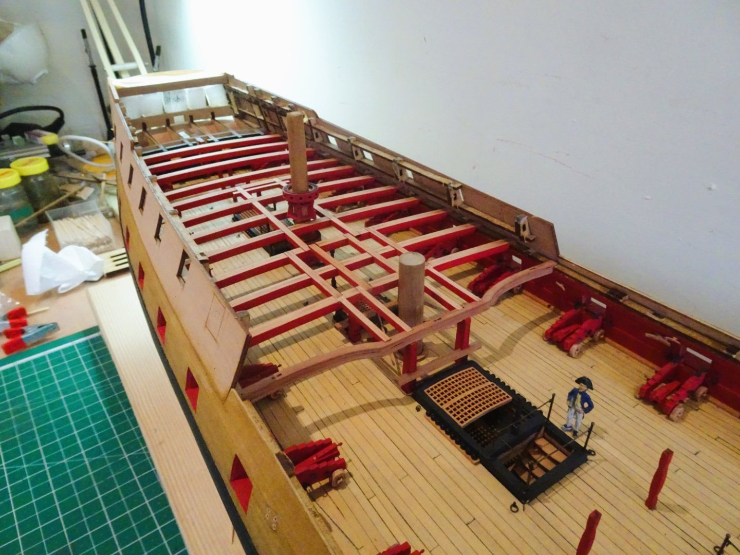
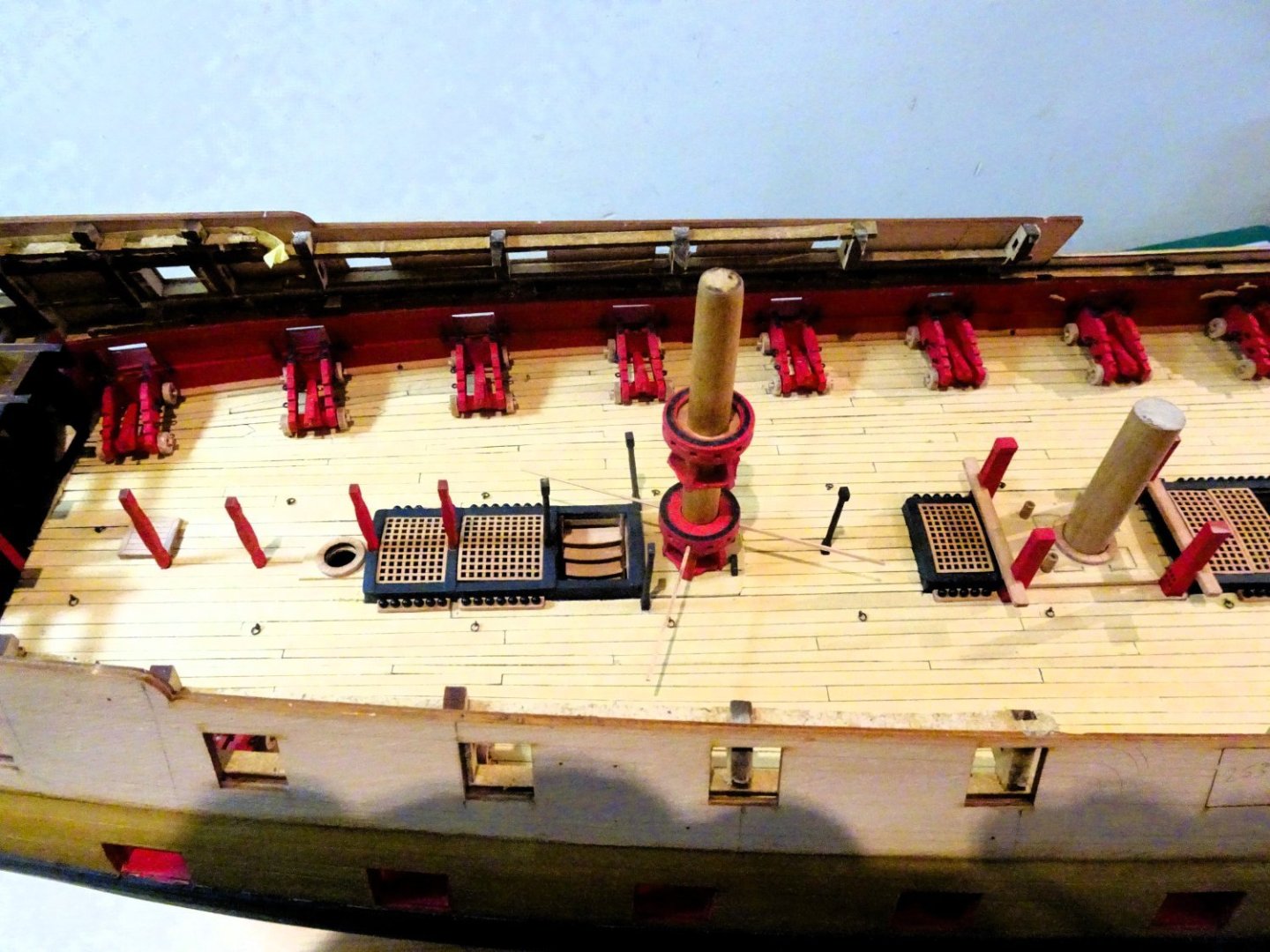
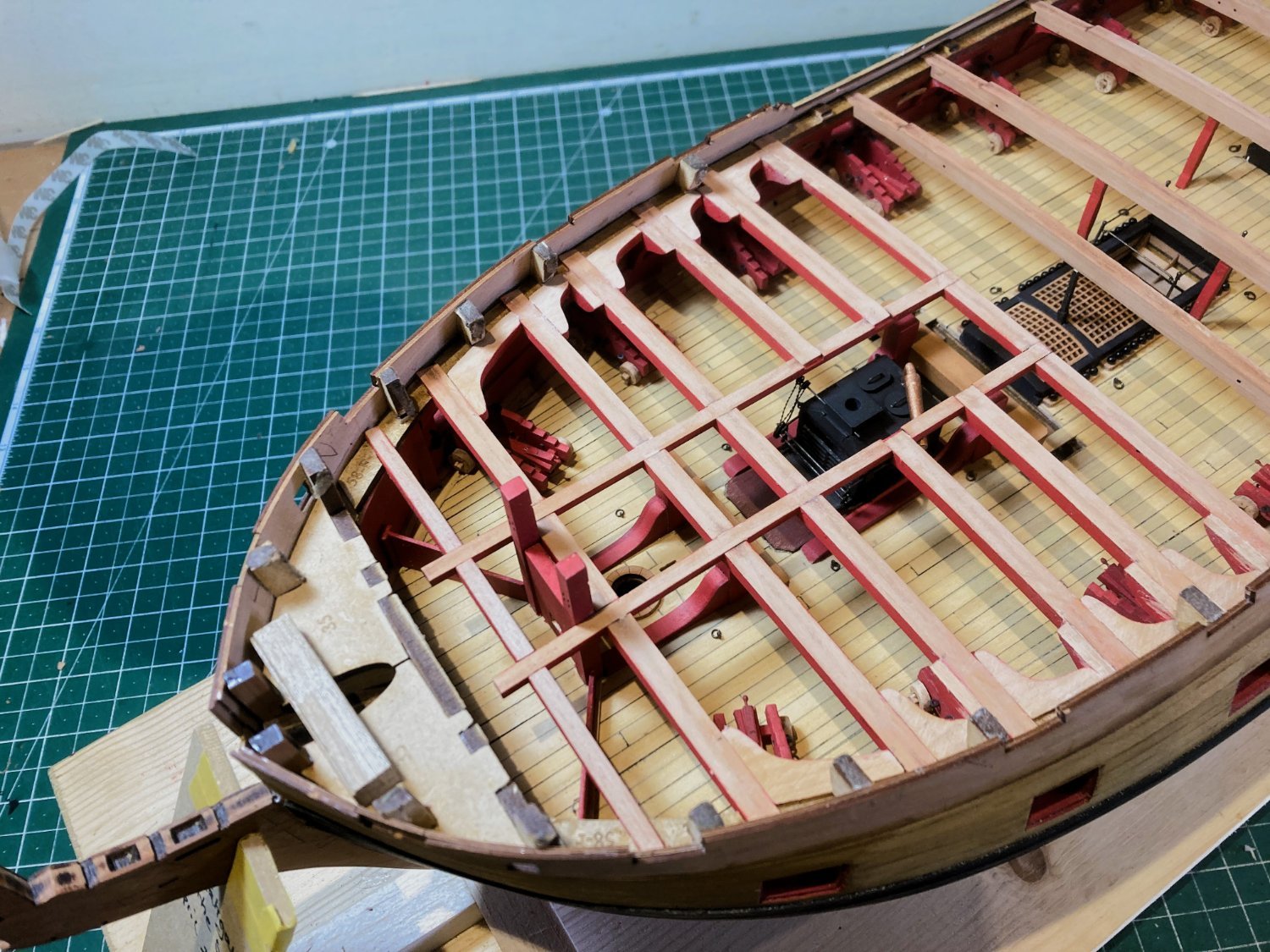
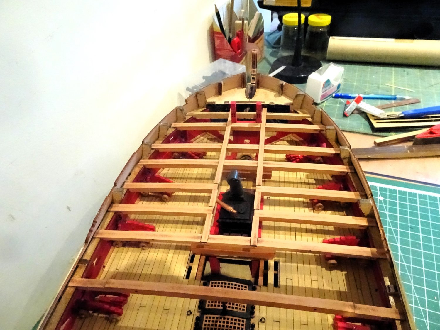
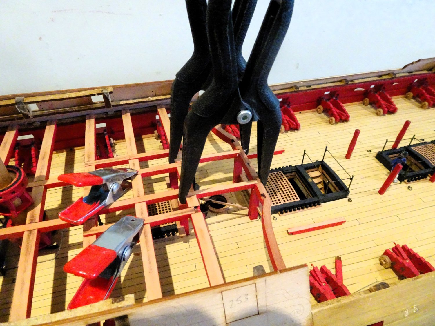
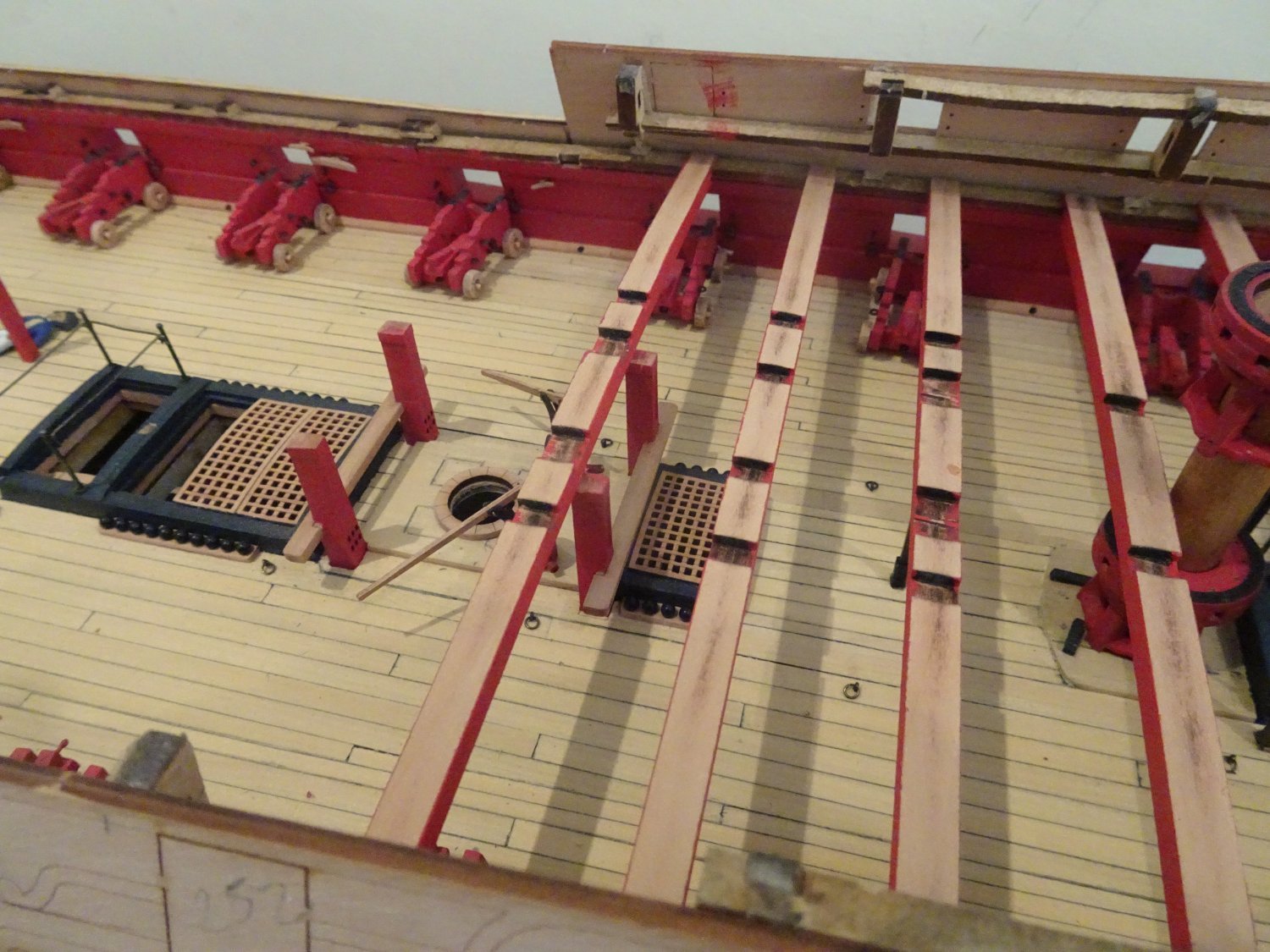
Post Seventy-six Carlings These slot beautifully into the beam mortises. 2002 I use clamps to ensure they sit right down once glue is applied. 2005 Only the outer carlings, adjoining the breast beam, were a tad slack in the fit, and needed a little fettlin’. 2022 2021 The more I look at this framework, the less I want to cover it up. 2023 It will be an interesting exercise to work out how I can use the minimum planking to the best effect. As I move on forward of the Qtr deck I had a change of heart about using the kit provided pillars atop the head ledges. 2006 They somehow look out of place, maybe because I raised and cambered the head ledges. 2016 2017 From this point on I decided to use ‘iron’ stanchions, they suited my eye better for this position. I will continue to use the provided pillars for the deck located beam supports. Moving onto the Foc'sle framing. B.E. 06/09/2023


- 648 replies
-
- 26
-
-

-
- Indefatigable
- Vanguard Models
- (and 1 more)
-
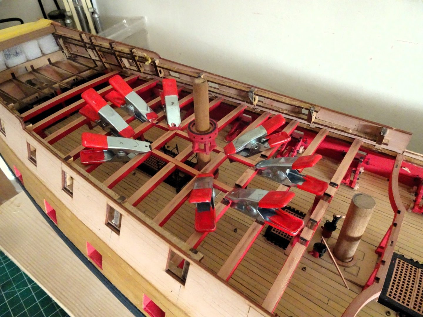
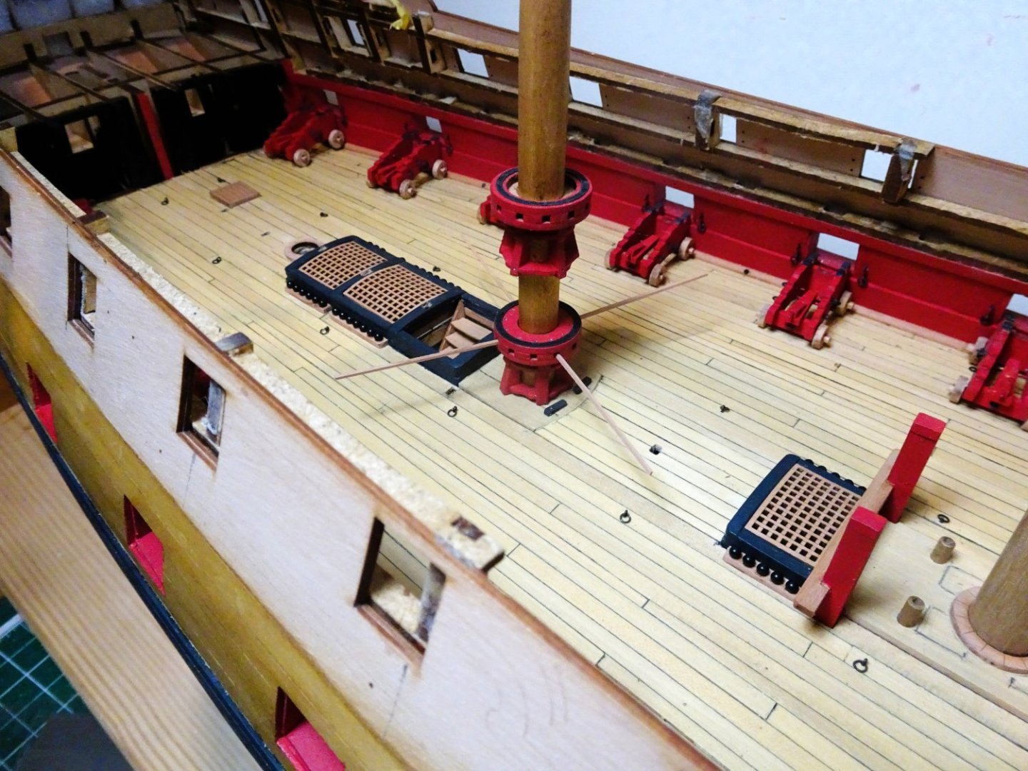
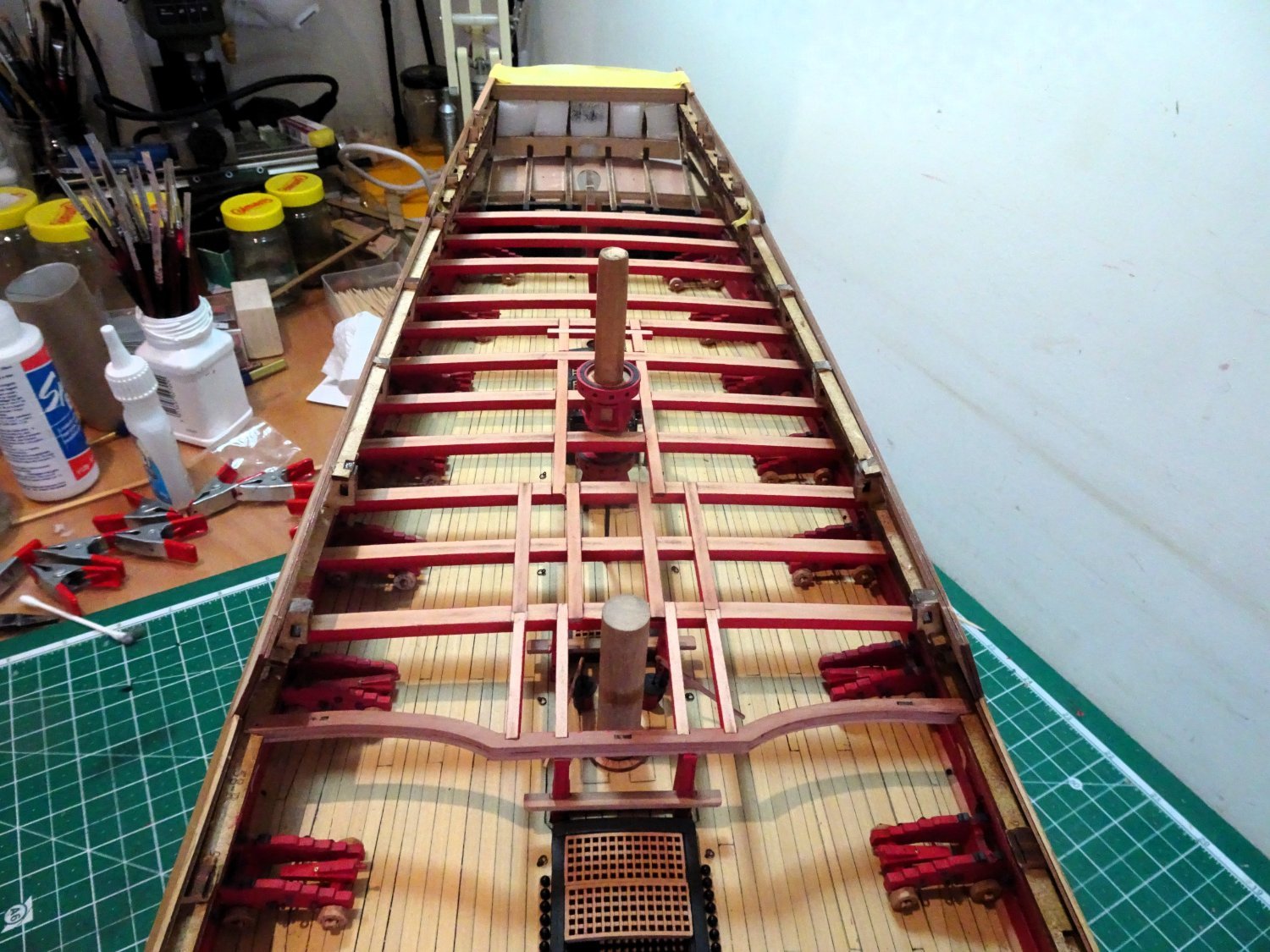
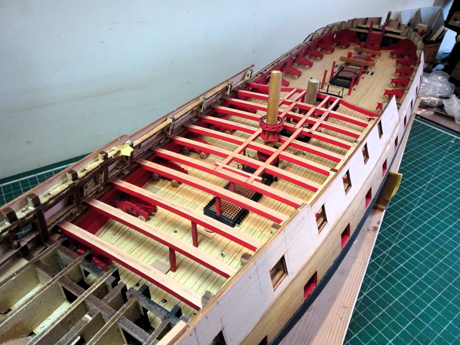
Post Seventy-five Fitting the Qtr deck beams With the Qtr deck beams painted, fitting can begin. 1997 Slow and careful is the order of the day. Moving from aft forward each beam is test fitted before gluing, and the central support pillars gradually trimmed to height to fit beneath the beams without forcing the camber. 1998 Constant checking is a necessity. If plan sheet 3 is used to aid location, there is a note to leave beam 14 off until part 103 (Carling) is fitted. This would be a mistake as it would prove very difficult if not impossible to retro fit 14 after the following beams have been fitted. Section 373 of the manual provides an alternative and more practical solution. 1991 I had a brief moment of panic fitting the final deck beam of the set (No9). I was expecting that it would be fully supported by the Main Jeer Bitt standards. Not so, it only catches the forward edge.(by design) 1989 The final beam is the Qtr deck breast beam supported at its centre by the Main Topsail sheet Bitts standards. Before fitting I gave it the heat treatment secured over the former, to ensure the camber was properly set. 1993 1999 1996 The Capstan barrel extends down to the lower deck and will be trimmed to height once the Upper capstan is seated on the QD step. 1995 I do like the shaped breast beam of these Ardent class ships. 1994 The final step will be to add the carlings. B.E. 05/09/2023


- 648 replies
-
- 25
-
-
-
- Indefatigable
- Vanguard Models
- (and 1 more)
-
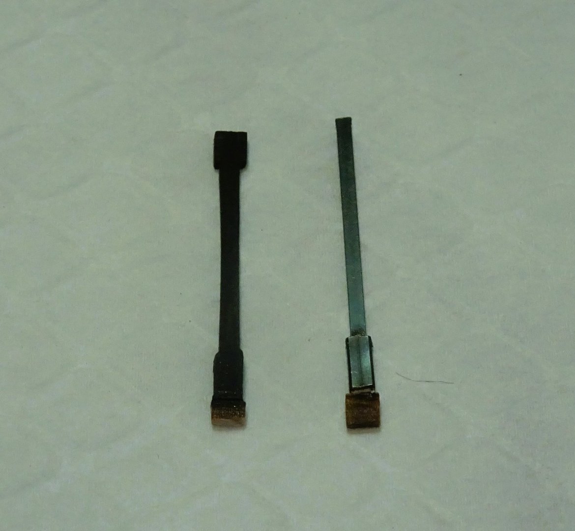
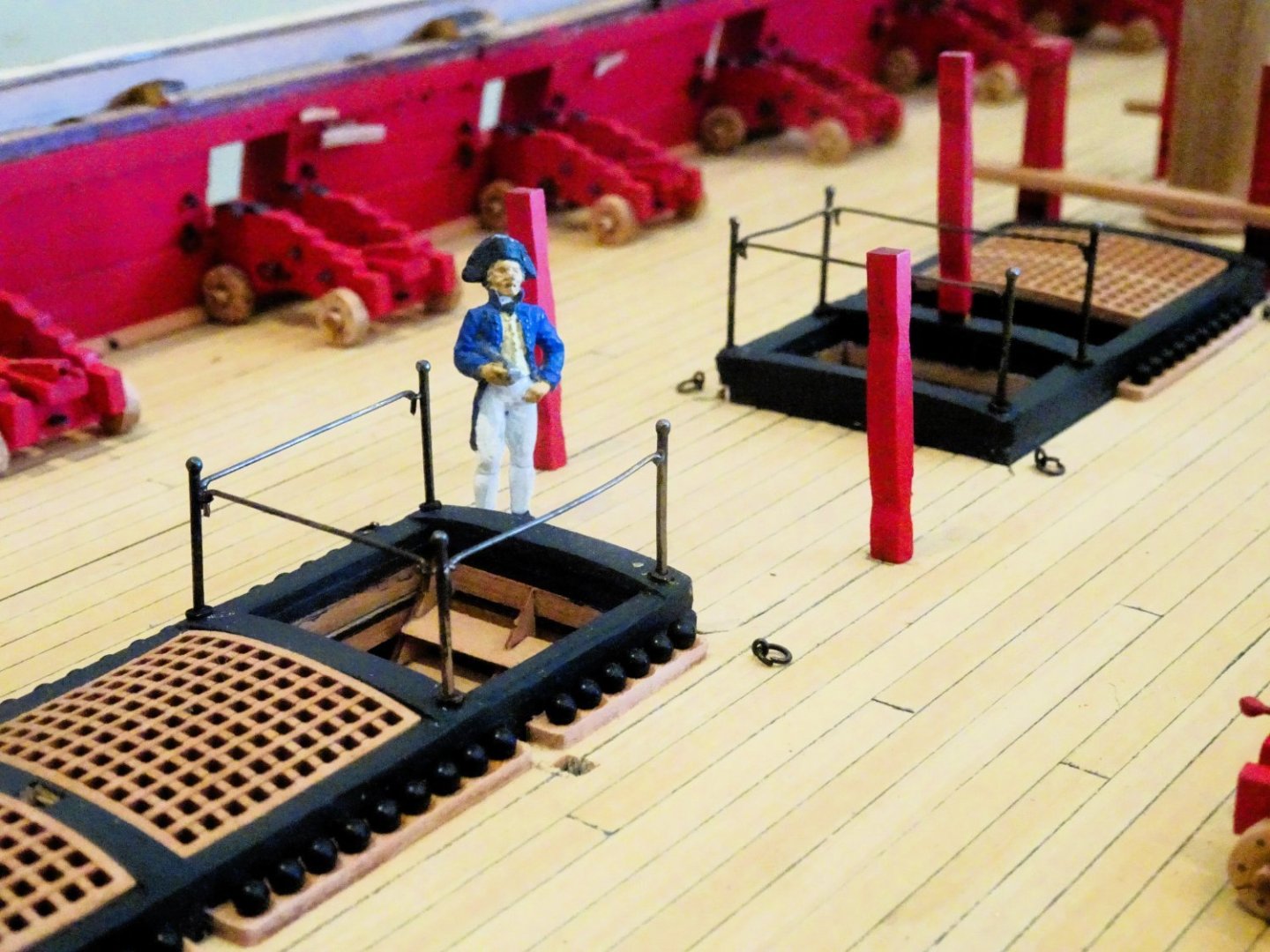
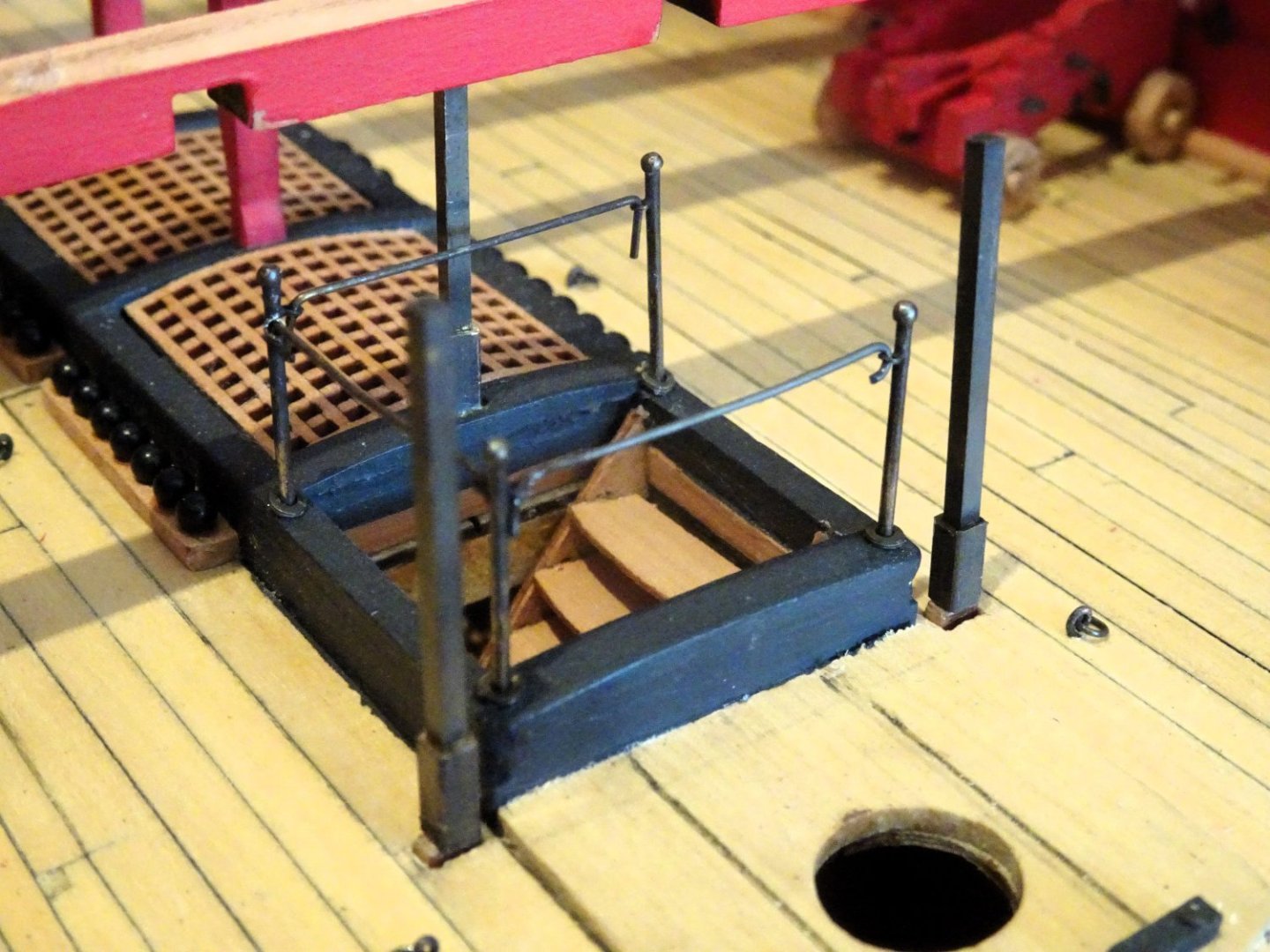
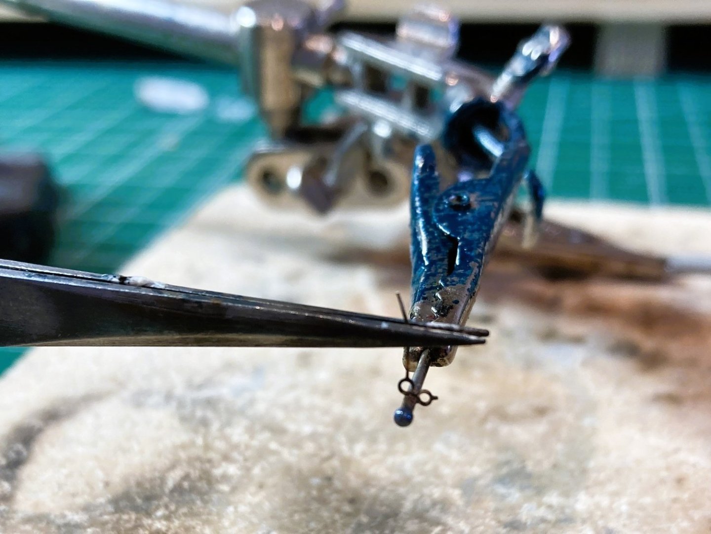
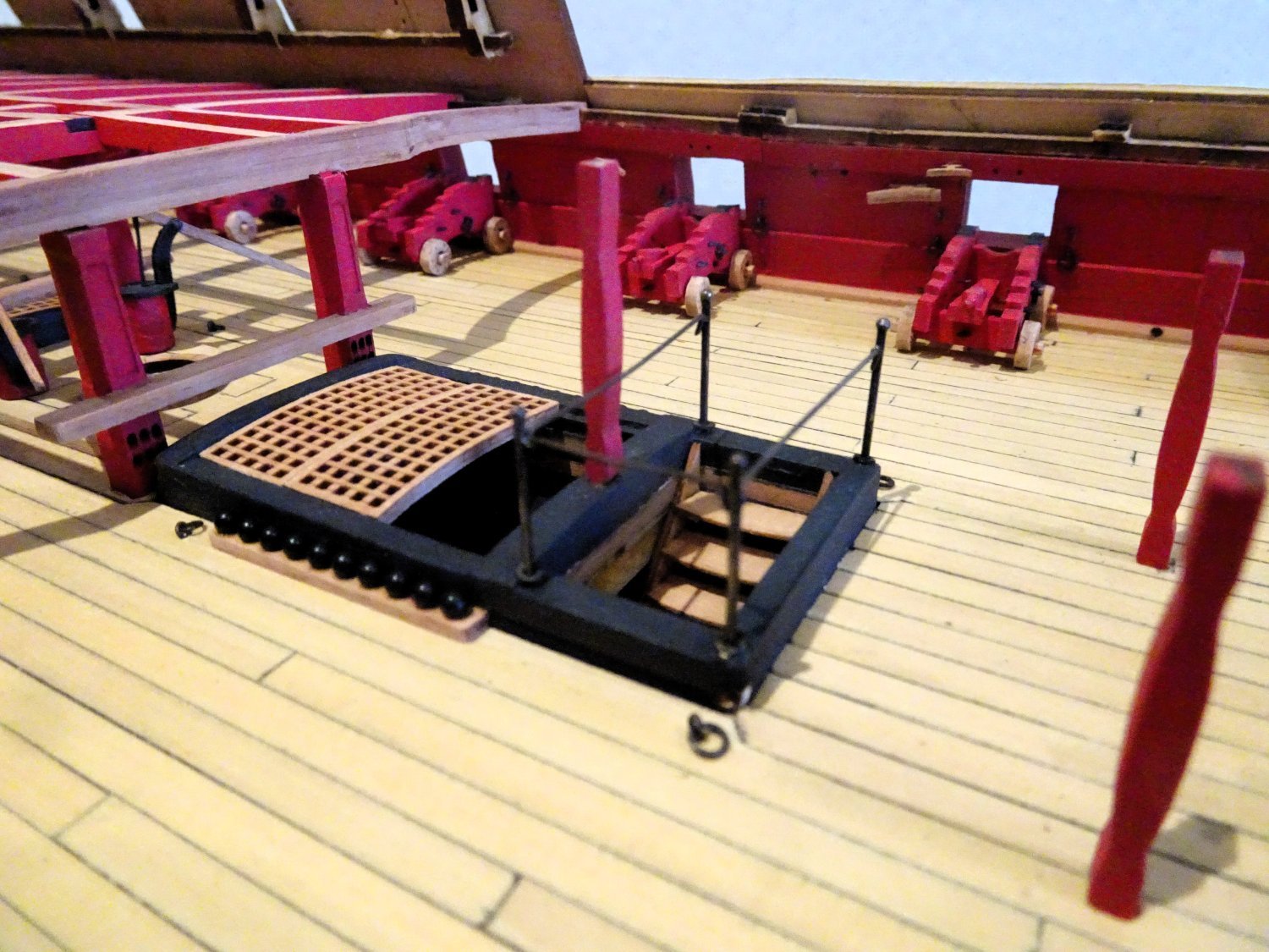
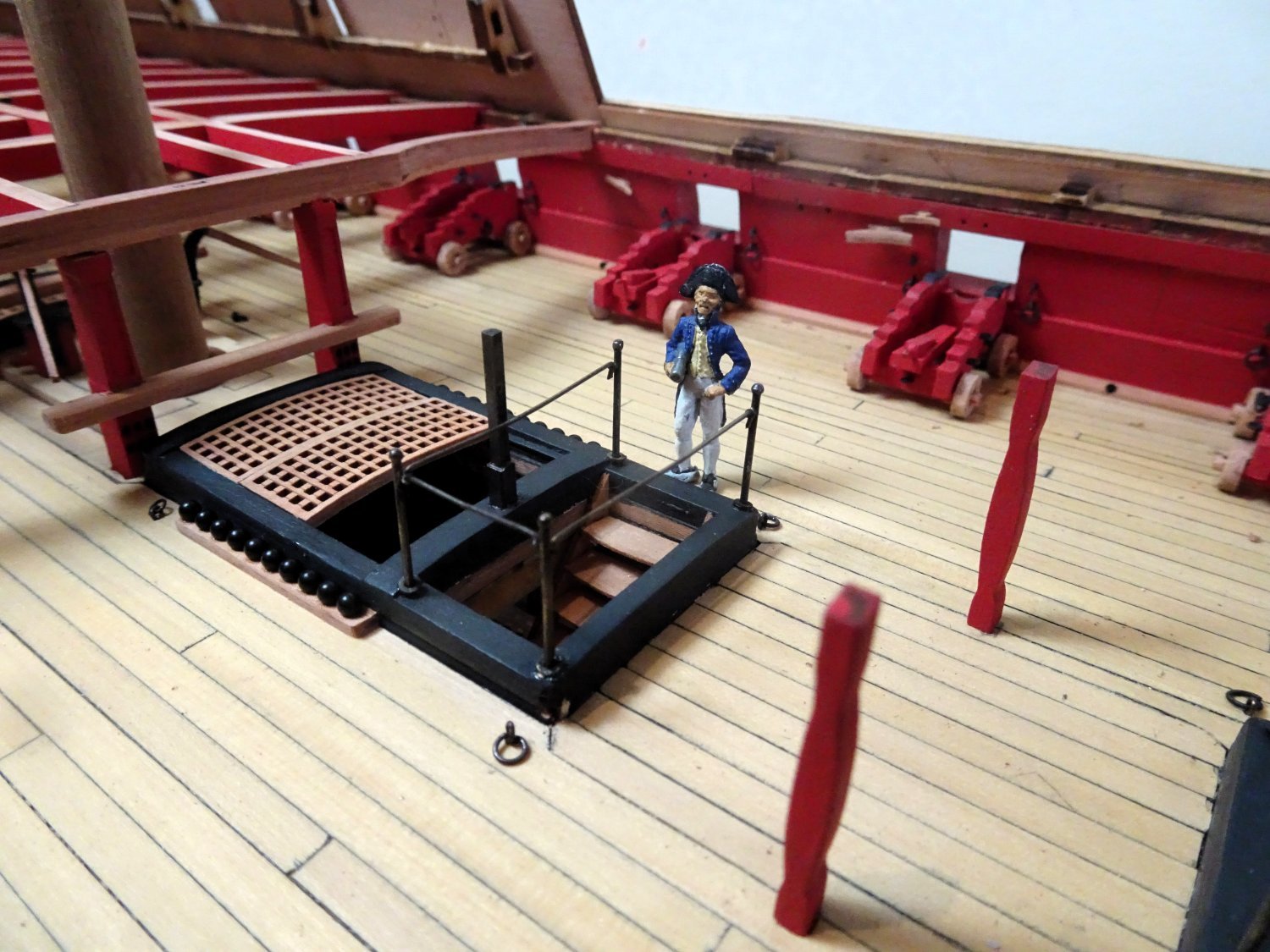
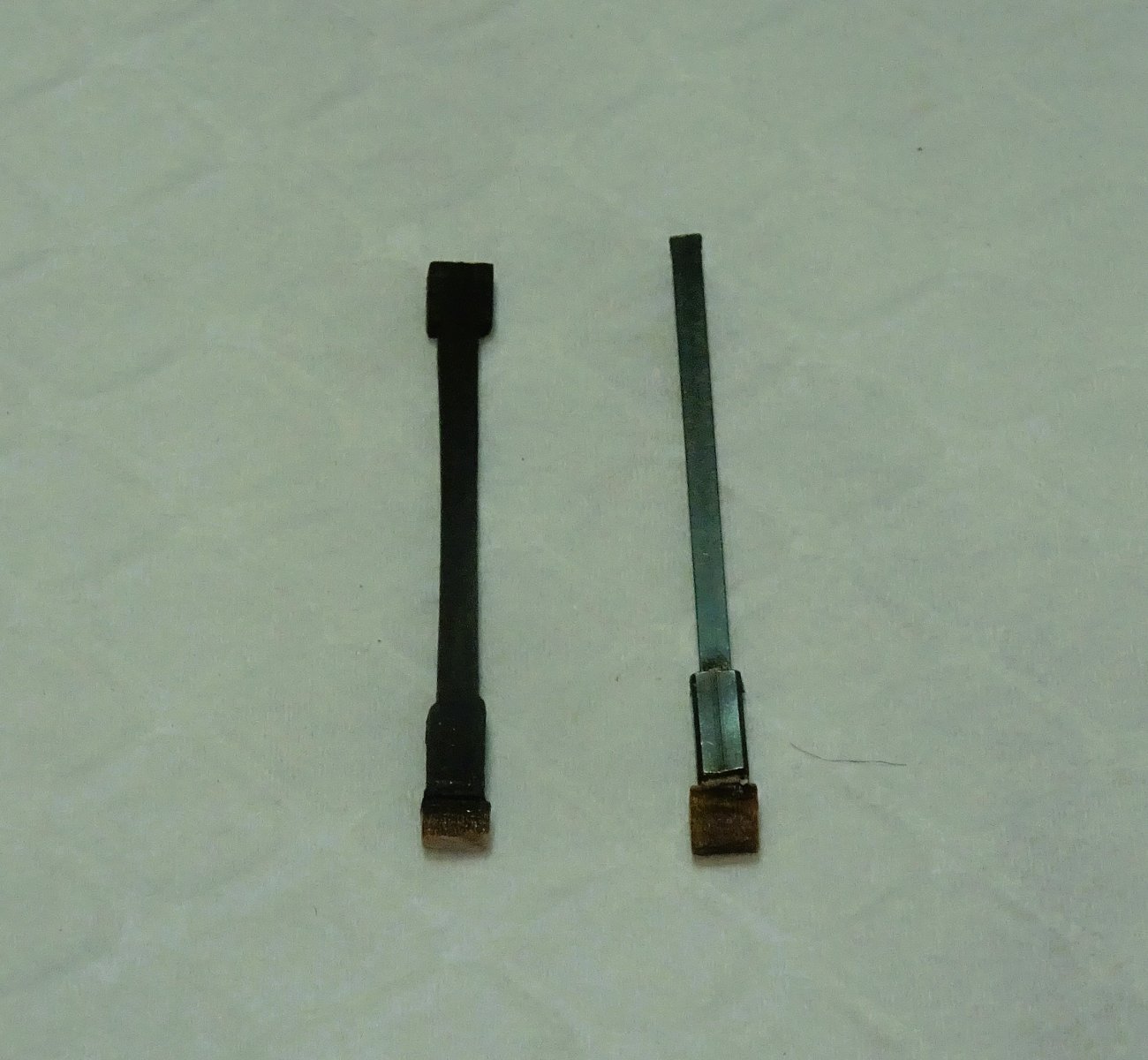
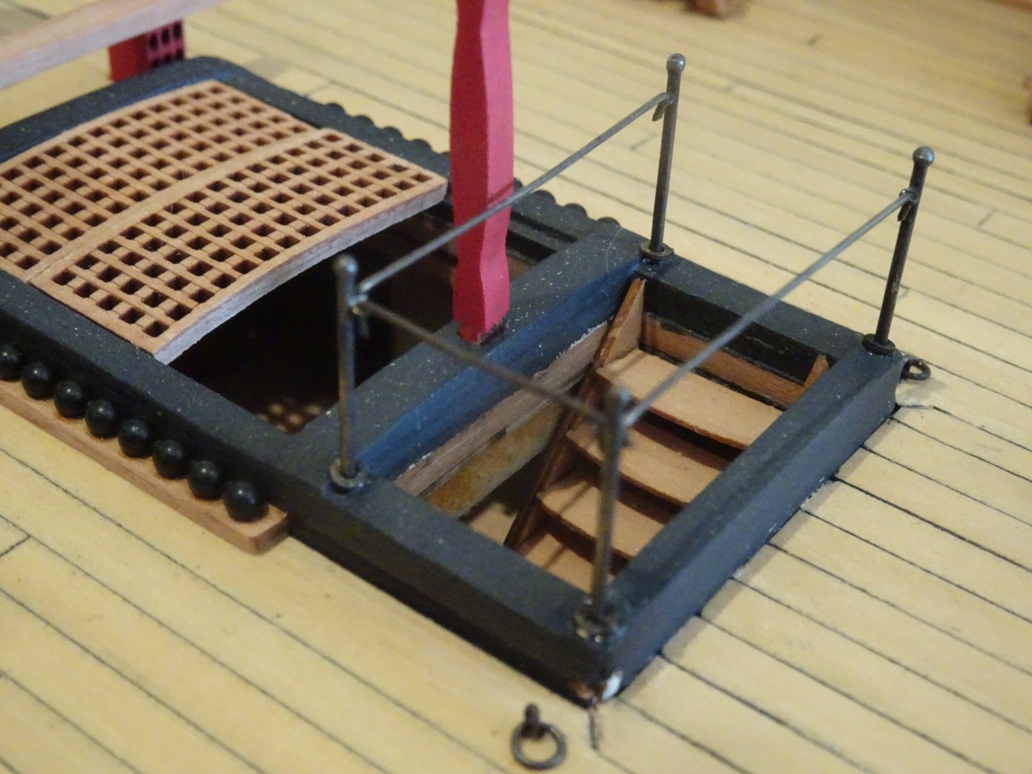
Post Seventy-four Stanchions on my mind I wasn’t really satisfied with my pillar conversion, so I had a play around with metal. 1969 Using square brass tubing (2.3mm) with the original wooden pillar tab inserted, I formed the foot of the stanchion. 1.5mm square section brass was used for the stanchion, ca’d into the top of the foot. 1971 1974 Chemically blackened, they provide a stronger contrast to the wooden support pillars. 1975 I think they look more representative of ‘iron’ stanchions. I will finish the top end brackets once I have the determined the correct height, as I fit the deck beams. The kit ladderway stanchions (or newels)are represented by brass etched posts with an eye, thro’ which line is threaded. On my builds from Pegasus onwards I have passed over kit stanchions in favour of something more stylish. For the stanchions I am using the same system I adopted for Pegasus, which was based on the detail in the fffm Vol 11. 6989(2) The makings involve having donor stanchions, the ones I use are 0.9mm ø with a 1.3mm finial. For the rings 0.3mm eyelets, (Caldercraft) are used, and 0.5mm ø brass rod for the rails. 1253 A spot of silver soldering is required to bring it all together. Silver solder paste in two melt points 690º and 671º are required. 7044 Full details of the procedure can be found in my Pegasus log (page 4 – post 91) but I used the same process on my Sphinx build (above) 1983 Main ladderway. 1986 Aft Ladderway. 1987 Main Hatch ladderway. Forward to the Qtr deck beams. B.E. 03/09/2023


.thumb.JPG.24d091e4cbb4e37d8ffca0abdd89f2ef.JPG)

- 648 replies
-
- 27
-
-
-
- Indefatigable
- Vanguard Models
- (and 1 more)
-
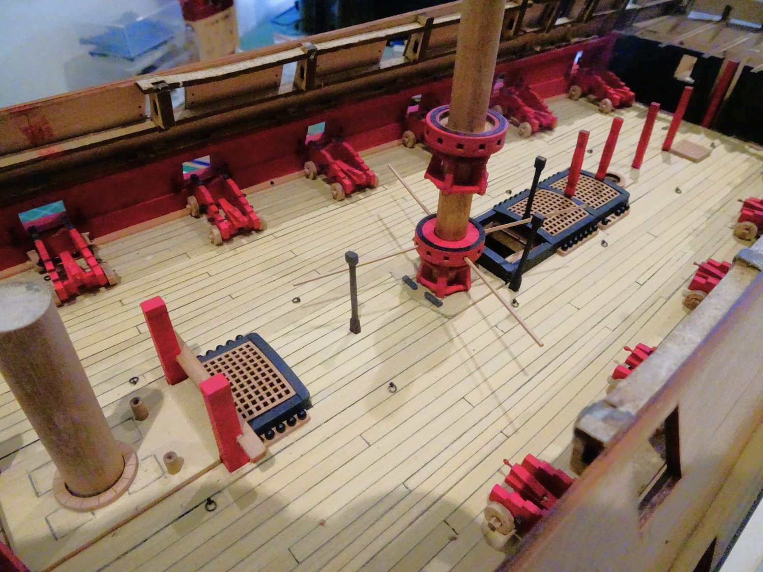
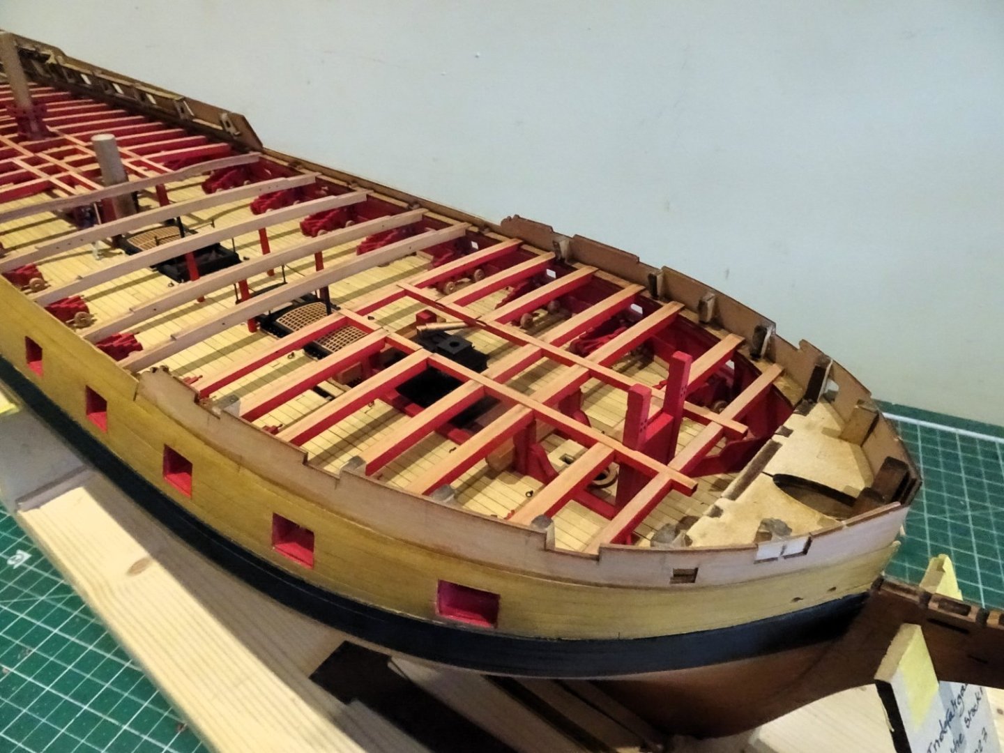
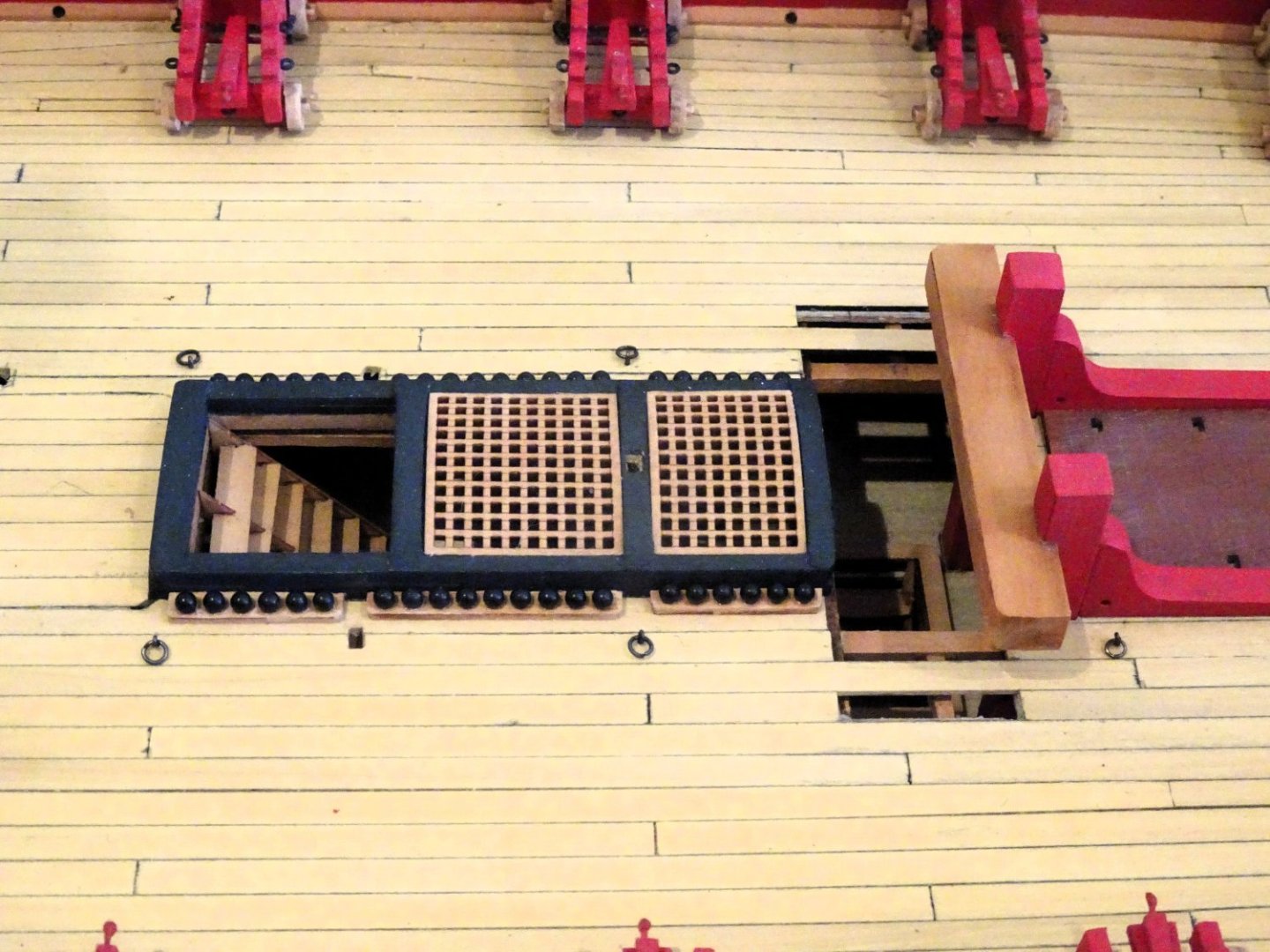
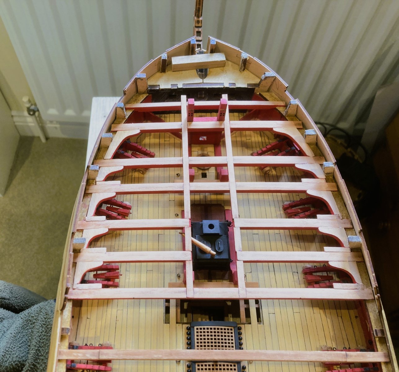
Post Seventy-three Back to the decks. Pre-occupied with the deck beams I nearly forgot about the gundeck ironwork. The kit provides etched eyebolts for the Training (relieving) tackle connection. These should strictly be ringbolts and I used 2mm rings and Amati fine eyebolts to make up the required number running along the deck binding strakes. 1950 For the first three sets aft of the Riding Bitts I have used 3mm rings to represent the stopper bolts. Apart from any other consideration ring bolts look nicer when looking down on the deck of a model. There is then the shaped deck support pillars and in particular those within the area of the Capstan. 1956 There are four within the radius of the Capstan bars which even with a modest scale 9’ length would impede movement. I think these would more likely be hinged iron supports that could be lifted out of the way when the capstan was in use. 1963 I have modified the pillars to represent such items, and which from the available viewing point would probably pass muster, at least to a blind man on a galloping horse. 1958 1967 I still may re-visit the iron stanchions and try a 1mm ø brass tube version. B.E. 31/08/2023

- 648 replies
-
- 20
-
-
-
- Indefatigable
- Vanguard Models
- (and 1 more)
-
Happy Birthday Kevin, you mean you have something better to do than ship modelling.😉 B.E.


.JPG.131ad251a4ee578ea9d7f764f29dc576.JPG)