
.JPG.ca33079f5815b861e67b9c2cccd37982.JPG)

Blue Ensign
-
Posts
4,572 -
Joined
-
Last visited
Content Type
Profiles
Forums
Gallery
Events
Everything posted by Blue Ensign
-
 There was nothing wrong with the original kit supplied deadeyes, it was just the scale I was concerned about. The replacement 4mm and 2.5mm deadeyes were ok but I should have ordered a few more to take the rejects into account. They will look ok before I fix them into place. Cheers, B.E.
- 857 replies
-
- 4
-

-
- Sphinx
- Vanguard Models
- (and 1 more)
-
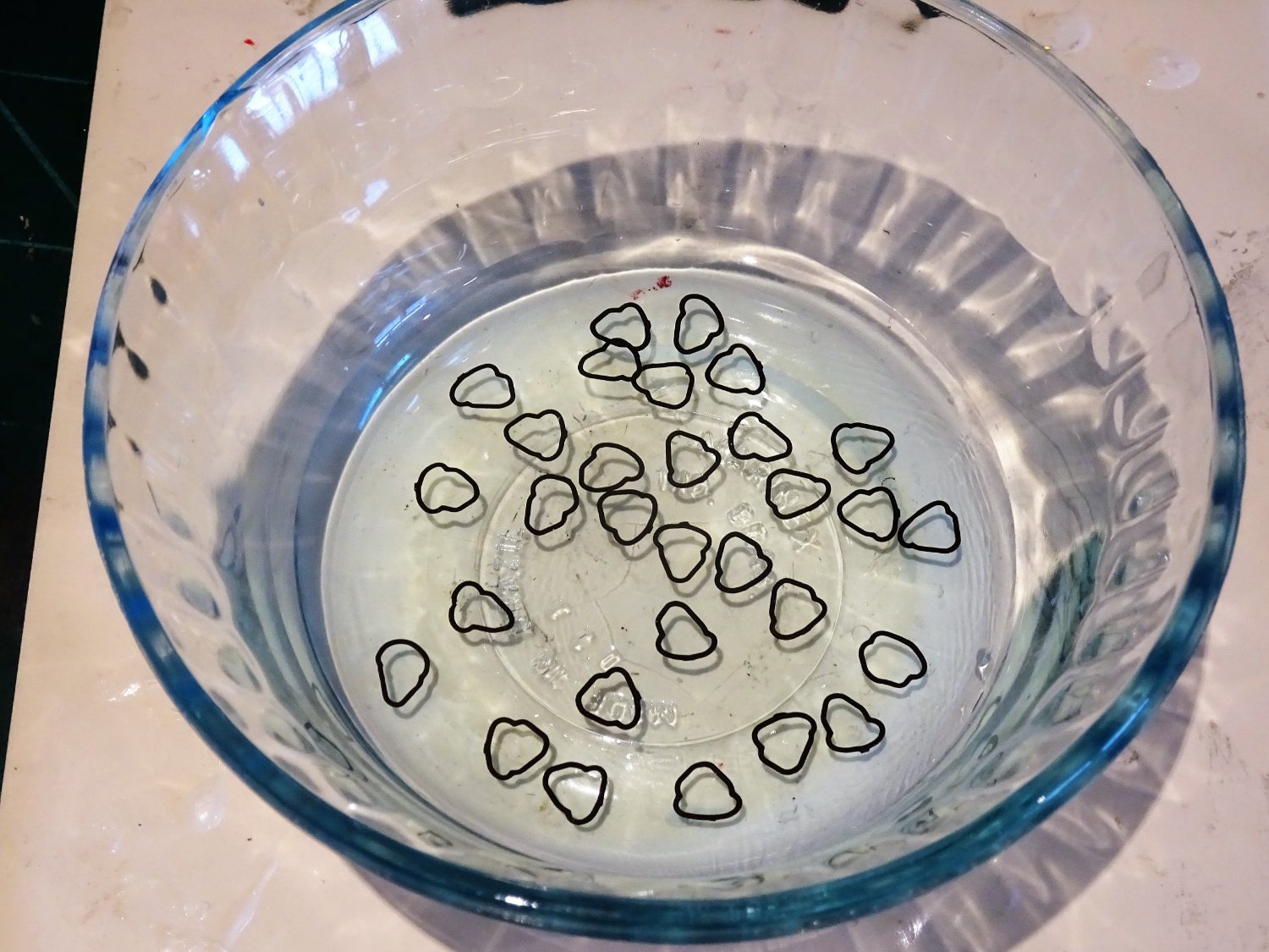
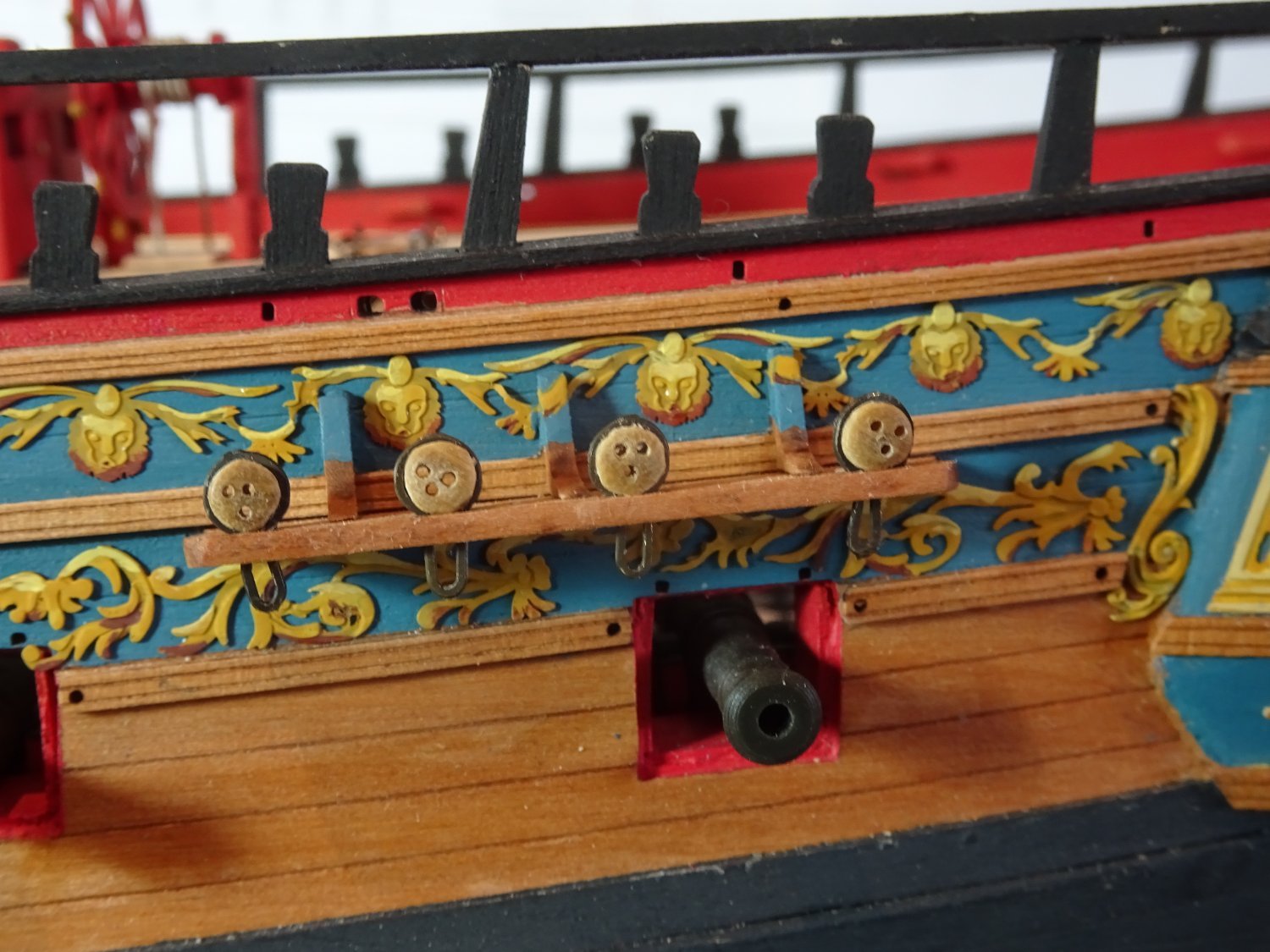
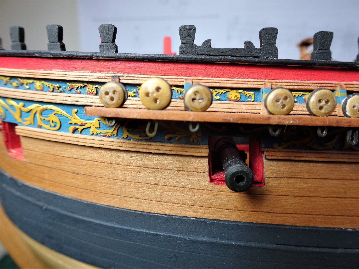
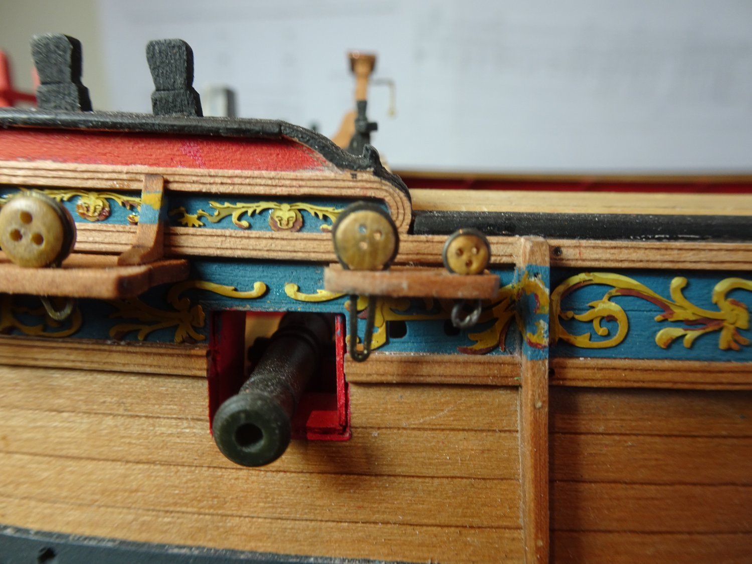
Post One Hundred and Thirty-one A question of Deadeyes. For my particular build only the Deadeyes for the lower shrouds and Backstays are required on the Channels. For ships of 20 - 22 guns Steel indicates Deadeye sizes 11”ø (Fore & Main shrouds) = 4.36mm at scale. 7”ø (Mizen shrouds) = 2.8mm at scale. 7”ø were also used for the Fore & Main Topmast Backstays. The stools abaft the Channels take the deadeyes for the Topmast (7”) and T’gallant mast (5”) standing backstays. The Mizen backstays are secured to the hull aft of the Channel. The kit provided items are of a pale Walnut colour, they look very similar to standard Amati deadeyes. They are nominally of 5mm and 3mm ø but are closer to 5.3mm and 3.8mm = 13.4” / 9.8” equivalent full sized deadeyes. Of the 5mm deadeyes; out of 67 provided, (9) were 5.17; (40) were 5.26; and (17) were 5.38mm. A touch of deva ju here, I had to tweak the deadeye sizes on my Pegasus build for a better scale look. I took a punt at ordering 2.5mm and 4mm deadeyes from Vanguard which I thought with the usual variances would come close to actual scale sizes. As I had hoped the 4mm deadeyes came out at 4.36mm and the 2.5mm deadeyes at 2.8mm, spot on for scale. The question then remains what to do about the T’gallant stay deadeyes of 5” = 2mm ø fitted to the stools. The following photos are for size comparison only, some of the deadeyes don’t meet muster as to hole positions and will have to be replaced. 7269 This photo shows a kit 5mm shroud deadeye compared to the 4mm size. 7264 The oversized kit 3mm deadeyes were reduced in circumference as shown here on the Mizen stool. 7265 7266 As on the Fore and Main channels above, the modified 3mm deadeyes give a good visual difference to the shroud deadeyes. 7270 The 2.5mm deadeyes are used for the T’gallant standing backstays on the stool, and again show a clear difference to the Topmast deadeye. At 1:64 scale these 2.5mm deadeyes are still a little oversized but are about the smallest size for practical use. Changing the Deadeye sizes does create an issue with the provided strops. 7259 I did have some Amati aftermarket strops which I used for the 4mm deadeyes, shown here being blackened having been opened up for fitting. It was necessary to make replacement strops out of 0.5mm ø brass wire for the smaller deadeyes. 7273(3) The Deadeyes and strops will now need fettlin’ before I move onto the chains and preventer plates. B.E. 11/06/2022


.thumb.JPG.c7172d47929f4a1b2bf8edddceb393bc.JPG)
- 857 replies
-
- 19
-
-
- Sphinx
- Vanguard Models
- (and 1 more)
-
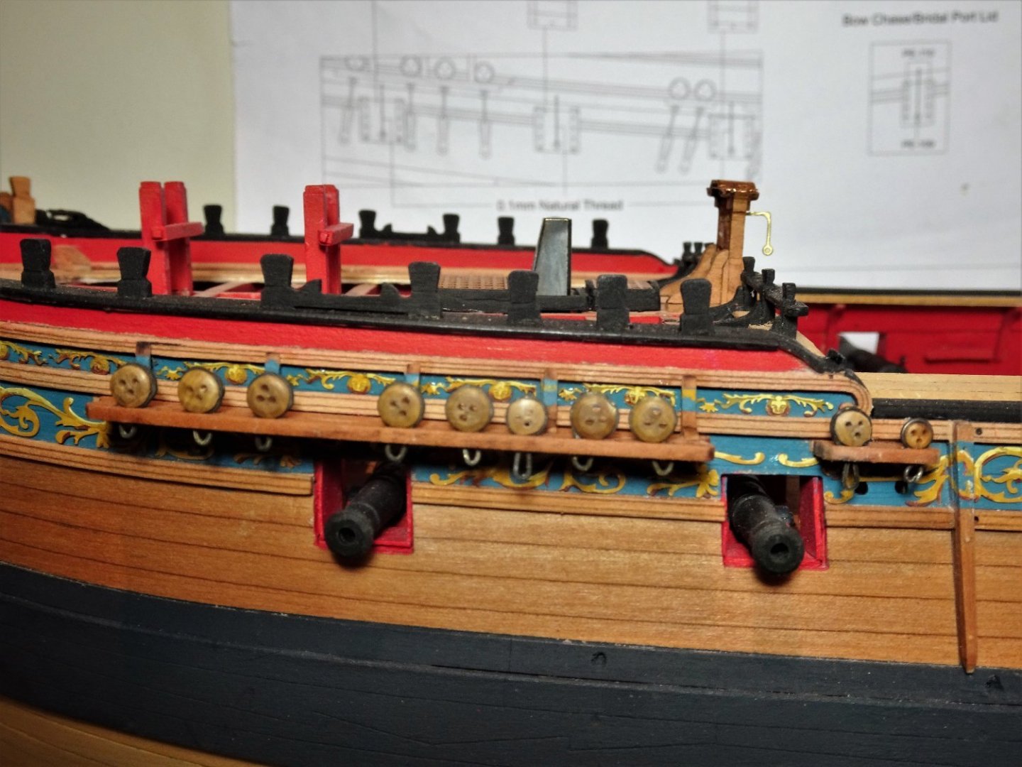
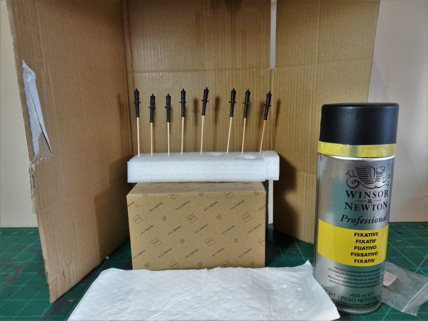
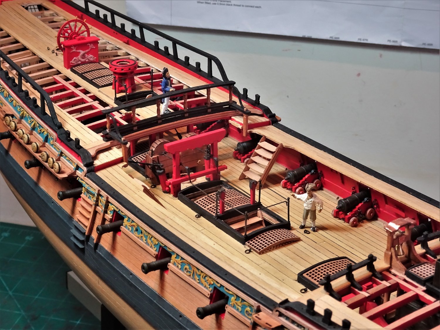
Post One Hundred and Thirty Ordnance complement completed. With fresh supplies received I can complete the remaining six waist guns. 02739(2) Amati fine copper pins and 2mm ø brass rings are used for the carriage iron works. 07242(2) 07243(2) A sort of milestone when all the guns are completed. 07248 07250 No gun rigging on this model, I’m following the Navy Board style. 07252 These are awkward guns to secure to the deck as their construction doesn’t lend itself to pinning. I use small dabs of pva on the wheels. 07256 Getting there! 07251 07257 I will be returning to the channels in my next post. B.E. 09/06/2022
.thumb.JPG.942ceef8a28fbd62e493ee967e483f24.JPG)
.thumb.JPG.0d8e0a368e49a14b1681ff7177d14aa1.JPG)
.thumb.JPG.e5f3131b22eb2f1e19bf8205148d2bff.JPG)


- 857 replies
-
- 22
-
-

-
- Sphinx
- Vanguard Models
- (and 1 more)
-
Thank you Bob and Andrew, I also have a selection of make-up brushes donated by Mrs W, and I use a large soft paint brush to run along the rigging lines, yards, and the deck. A lot of deck fittings are not fixed on my models, and are removed for cleaning. I also use cotton buds for difficult areas. My two largest uncased models - Norske love and a Flower Class Corvette are yet to do, but I'm still working up the enthusiasm to start.🙄 Cheers, B.E.
- 857 replies
-
- 3
-
-
- Sphinx
- Vanguard Models
- (and 1 more)
-
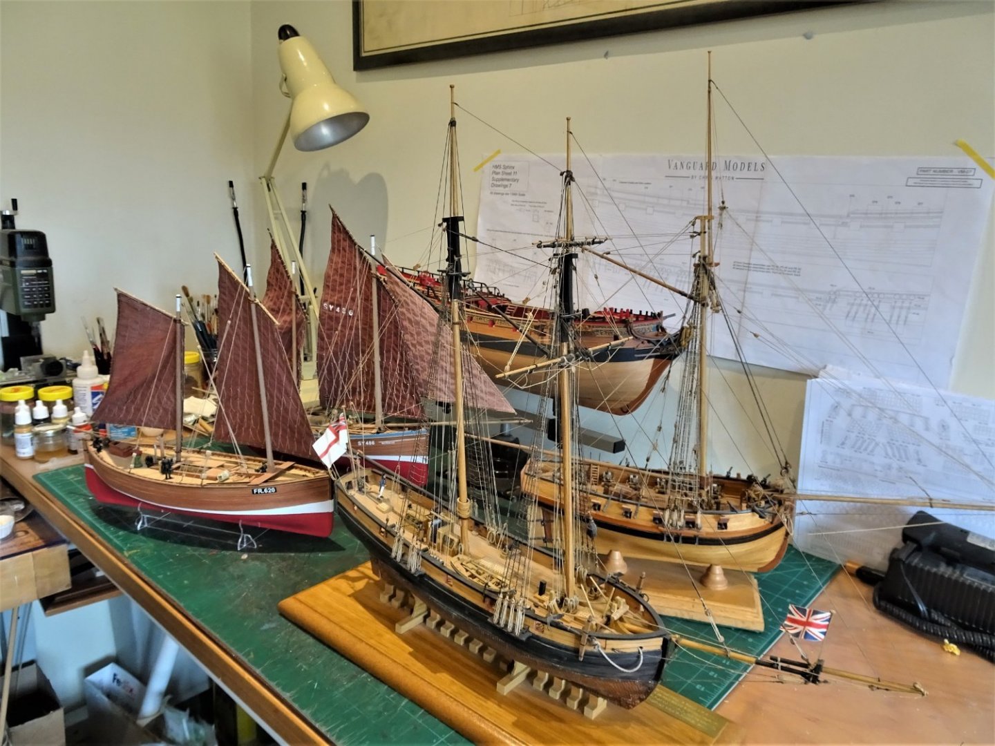
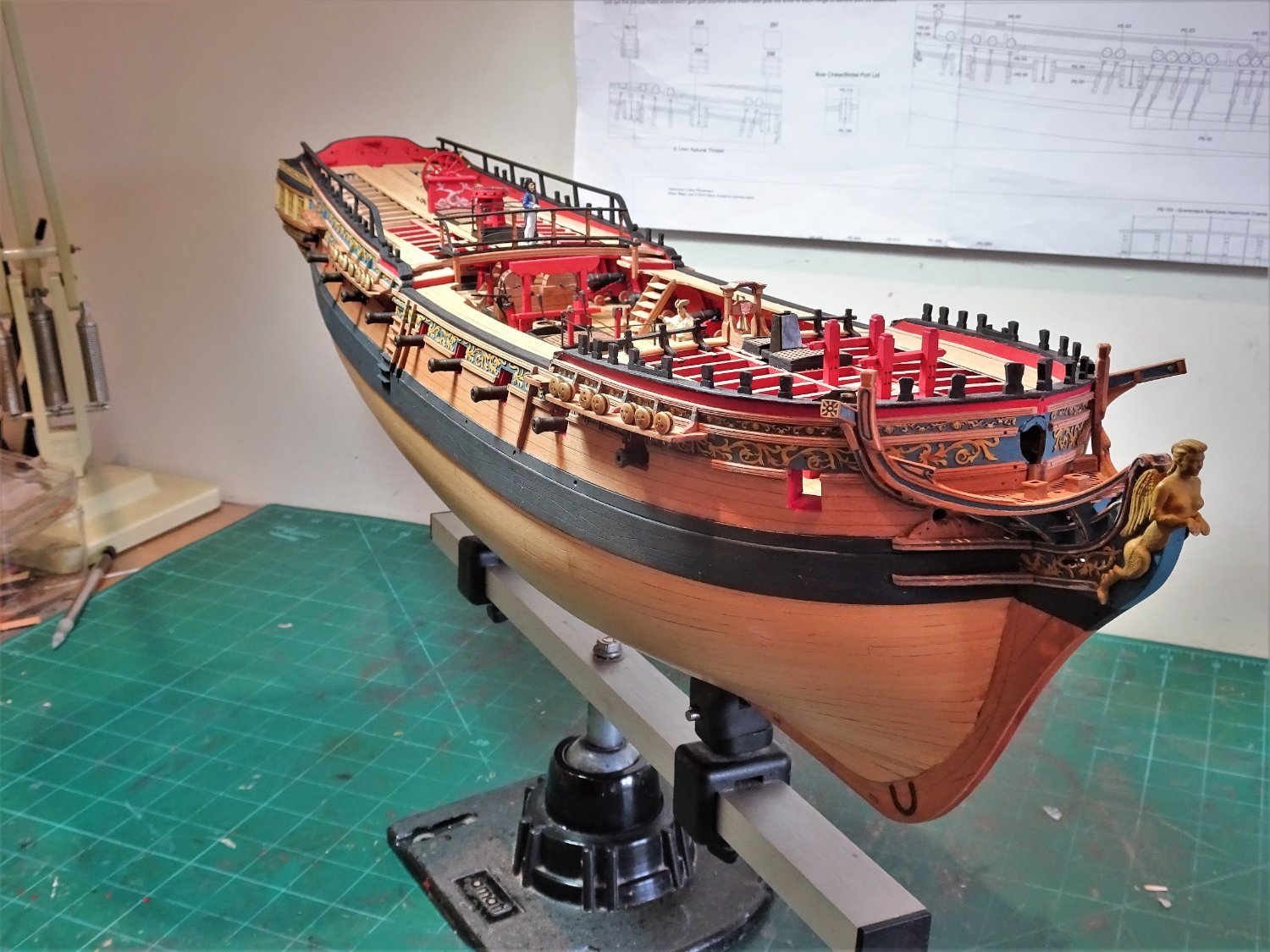
A slight diversion Work is temporarily stopped on Sphinx while I await fresh supplies. Not a job I look forwards to, but an opportunity to attend to a long overdue cleaning session of my uncased collection. 7229 The models are assembled from around the house. 7232(2) These particular models cover a span of some thirty years. English Cutter (Mamoli) 1990 HMS Pickle ( Caldercraft) 2010 Fifie (Vanguard) 2020 Muirneag (Zulu) ( Vanguard)2020 At least Mrs W who’s currently out golfing, will be pleased when she returns, she likes my models but is always on my case to clean them. B.E. 07/06/2022
.thumb.JPG.0586f707f7a4c35f81ff7e9a8644bdc4.JPG)
- 857 replies
-
- 19
-
-
-
- Sphinx
- Vanguard Models
- (and 1 more)
-
Nicely done Richard, a sweet little model. Are you going to display it on a waterline setting? B.E.
-
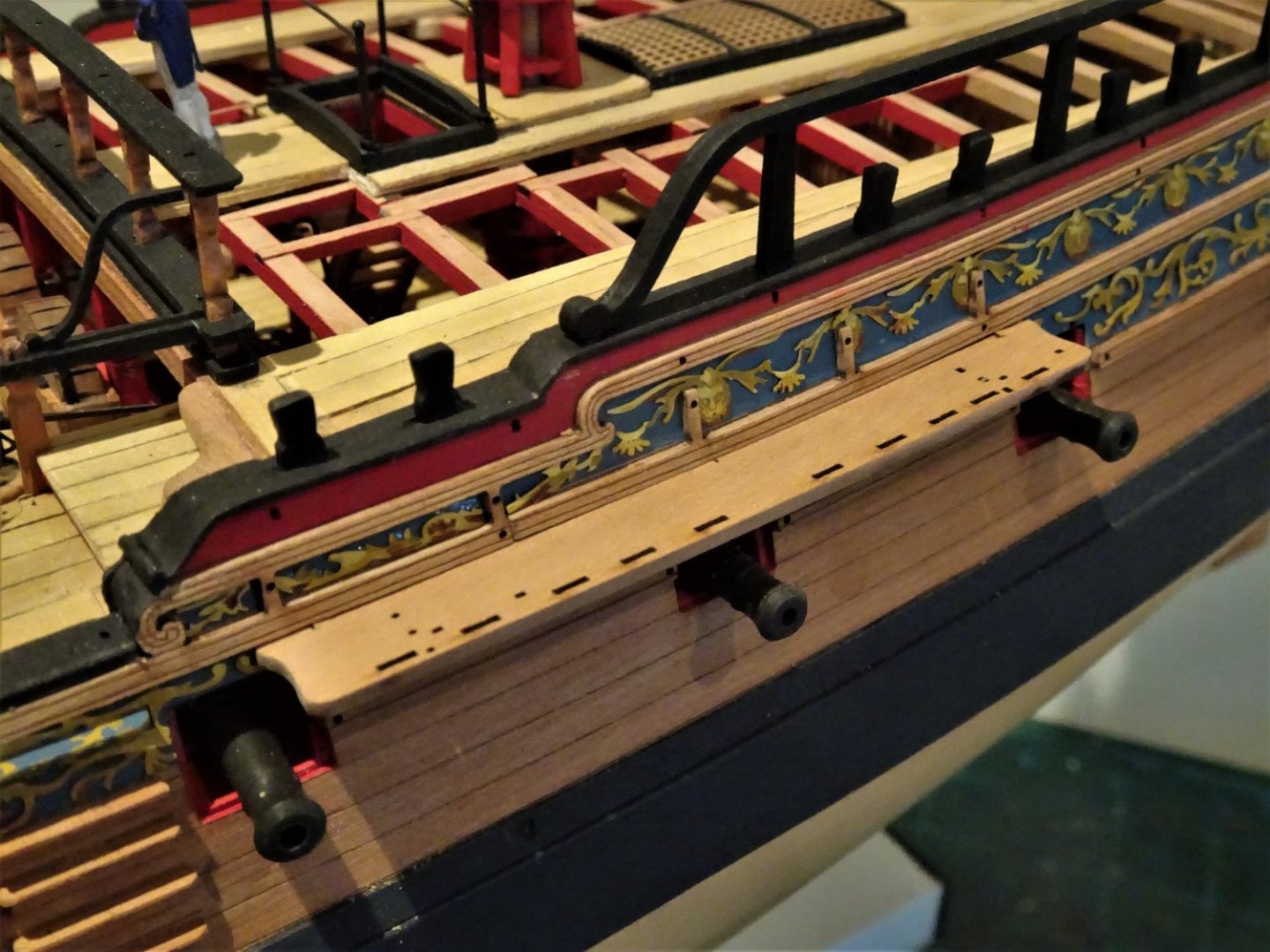
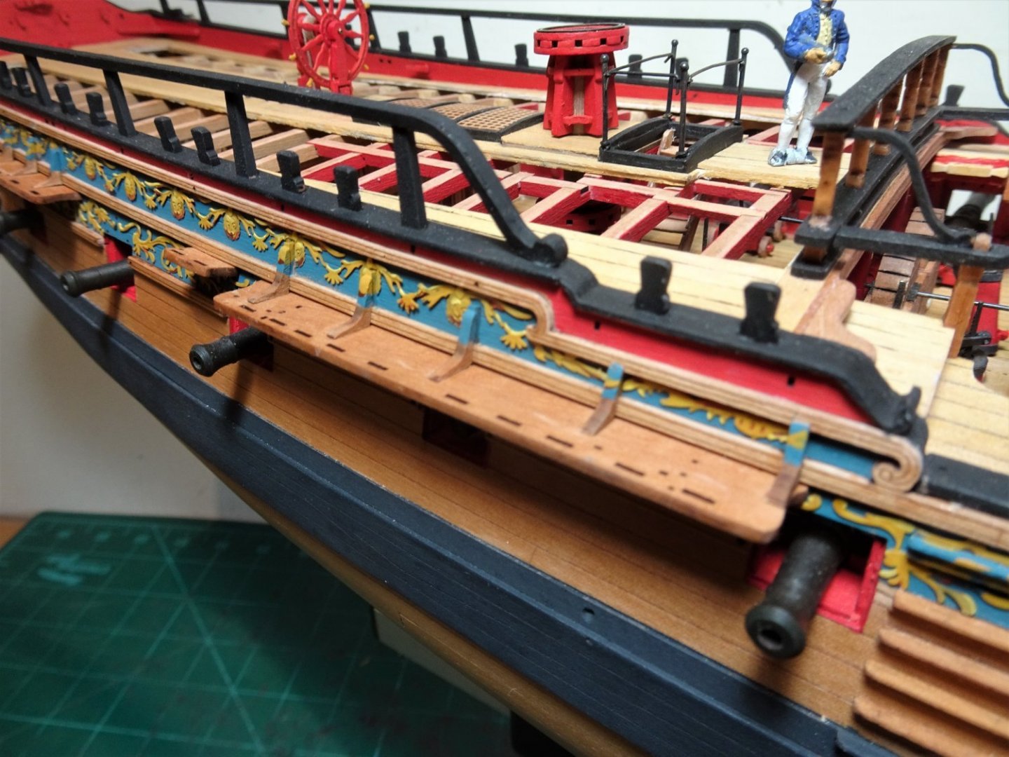
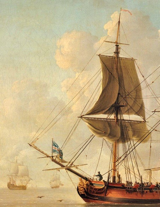
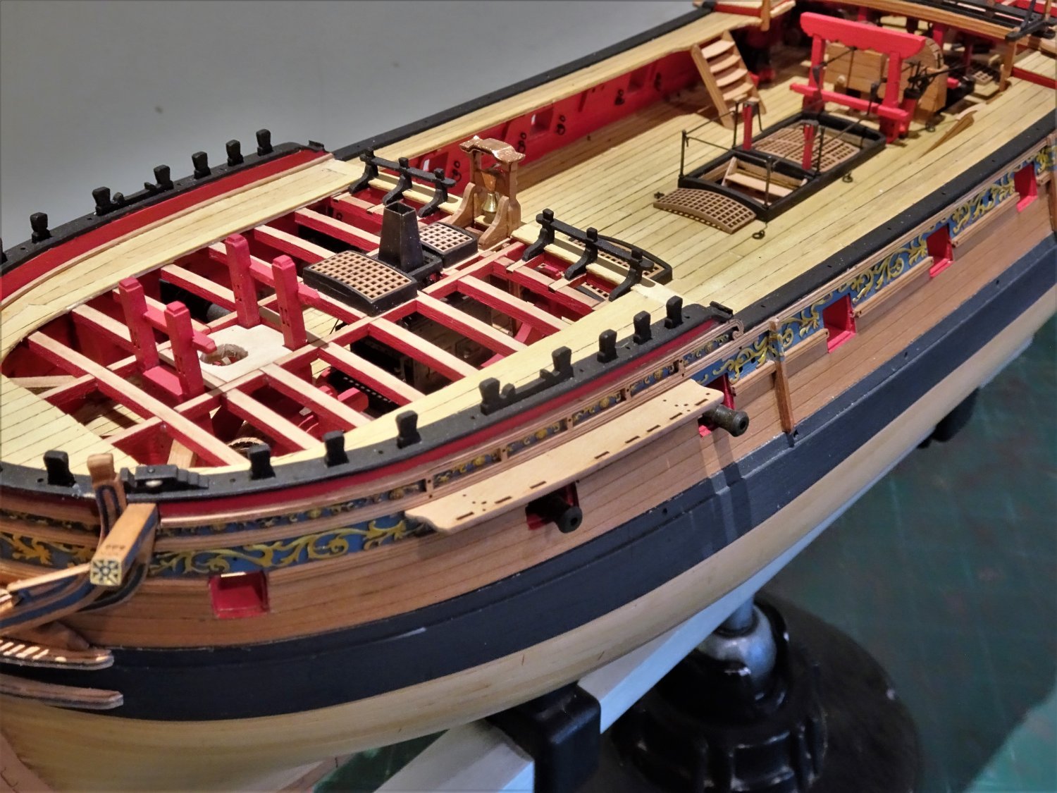
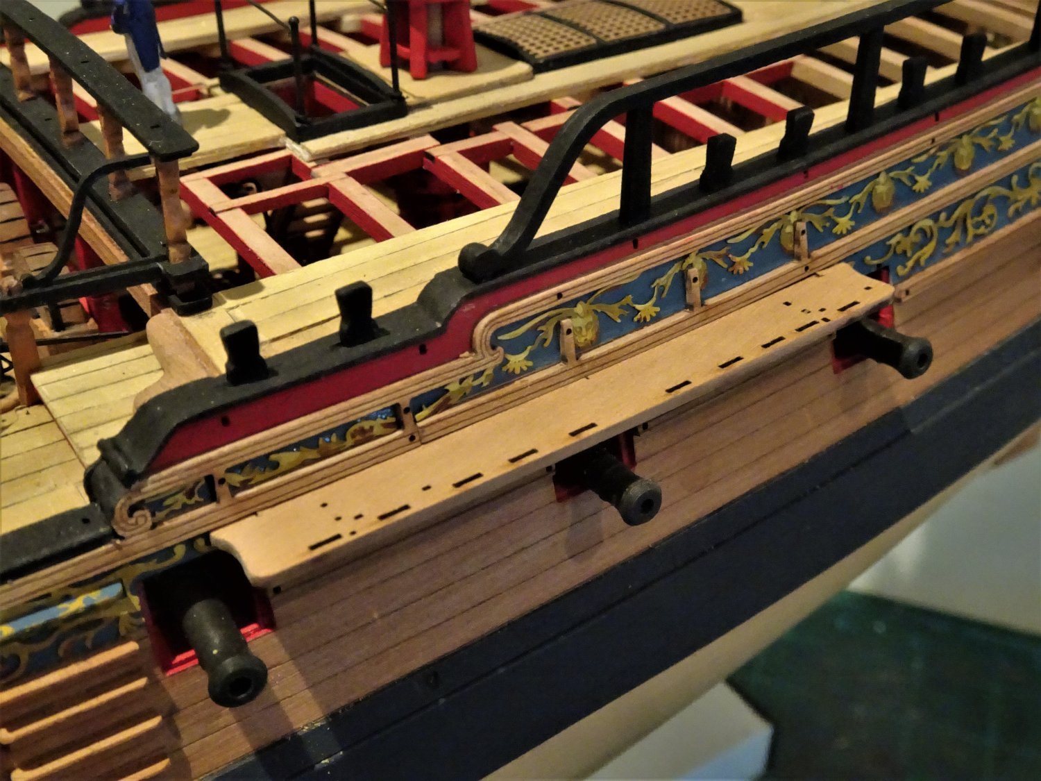
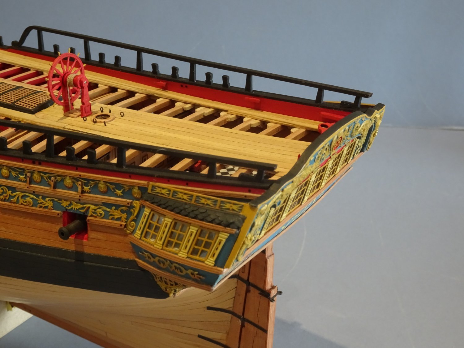
Post One Hundred and twenty-nine The Channels These are nicely formed out of Pearwood but are simplified to the extent that what would normally be a covering board along the edge of the channels to enclose the deadeye slots, is incorporated. This is relevant for me firstly because I was thinking of applying a fancy moulding along the edge. Secondly there is the question whether to paint the channels black, leave them bright, or leave just the moulding bright. In the Marshall painting the channels have bright edge mouldings, the upper sides are not clearly defined. 7197 However, when I try the channels against the model I think aesthetically they look best left bright. 7198 Only trial fitted here, I will apply w-o-p before fitting. I considered sanding down the forward edge of the channels to make room for a covering board but I was wary of spoiling the shape of the channels, particularly the shaped fore and aft edges. I trialled scribing a relief into the edge of some 1.5mm scrap, but with only that width to play with, creating something that represented a moulded shape was a non starter. I thought about adding a scribed covering board but that makes the width between slots and edge too great and still has the problem of producing a clean moulding. When I look at the channels in place on the model, given the scale I decided to leave them as is. I detect that Chris seems to have addressed this point on his new Indy model.🤔 There are (26) supporting brackets for the channels which are marked on the hull against which these tiny little fittings abut. 7200(2) These are channel and position specific, so were sorted into six separate containers for the tiresome task of char removal. I had a good run at these only two breakages (repaired) and several escapees (all recovered) Fitting the channels is easy stuff with retaining pins added as per the blurb. Adding the knee support brackets a little more tricky keeping the glue spread to a minimum. 7205 7202 7203 7204 The tops of the knee supports required painting to match the Topsides frieze. 7208(2) 7209(2) The next task is to decide which Deadeyes I will use and prepare the chain and preventer plates. B.E. 06/06/2022

.thumb.JPG.036fb092fc20c1cf9cf81b5698a52aaf.JPG)

.thumb.JPG.104289d750f7a227e5a4f3226413ec7b.JPG)
.thumb.JPG.1e78566130df1685bb791081c69e9f5f.JPG)
- 857 replies
-
- 27
-
-
-
- Sphinx
- Vanguard Models
- (and 1 more)
-
Hi Derek I've scoured my reference books looking for a comparable arrangement and the nearest thing I came across was this painting by John Cleveley the elder, of a sloop dated around 1740. As you can see the ratlines do span the larger distances between 3 and 4 and 4 and 5 I think I would have to try them across all shrouds and make an aesthetic decision based on how it looked to my eye. One other thought, the space on the Duchess aftermost shrouds is quite narrow, and ratlines purely between those two shrouds may look very cramped. Regards, B.E.
- 345 replies
-
- 2
-
-
- Duchess Of Kingston
- Vanguard Models
- (and 1 more)
-
I wonder if Chris can throw any light on the arrangement which does look a little out of the norm for ratlines to cross that span. What is the scale distance between the shrouds either side of the gun port? B.E.
-
Ha, Ha, Derek, you jest of course, remember I've seen your stuff. B.E.
- 857 replies
-
- 3
-

-
-
- Sphinx
- Vanguard Models
- (and 1 more)
-
Thank you Ron, The macro is a useful tool to address issues of finish, but I don't let it enslave me, therein lies madness. B.E.
- 857 replies
-
- 4
-
-
- Sphinx
- Vanguard Models
- (and 1 more)
-
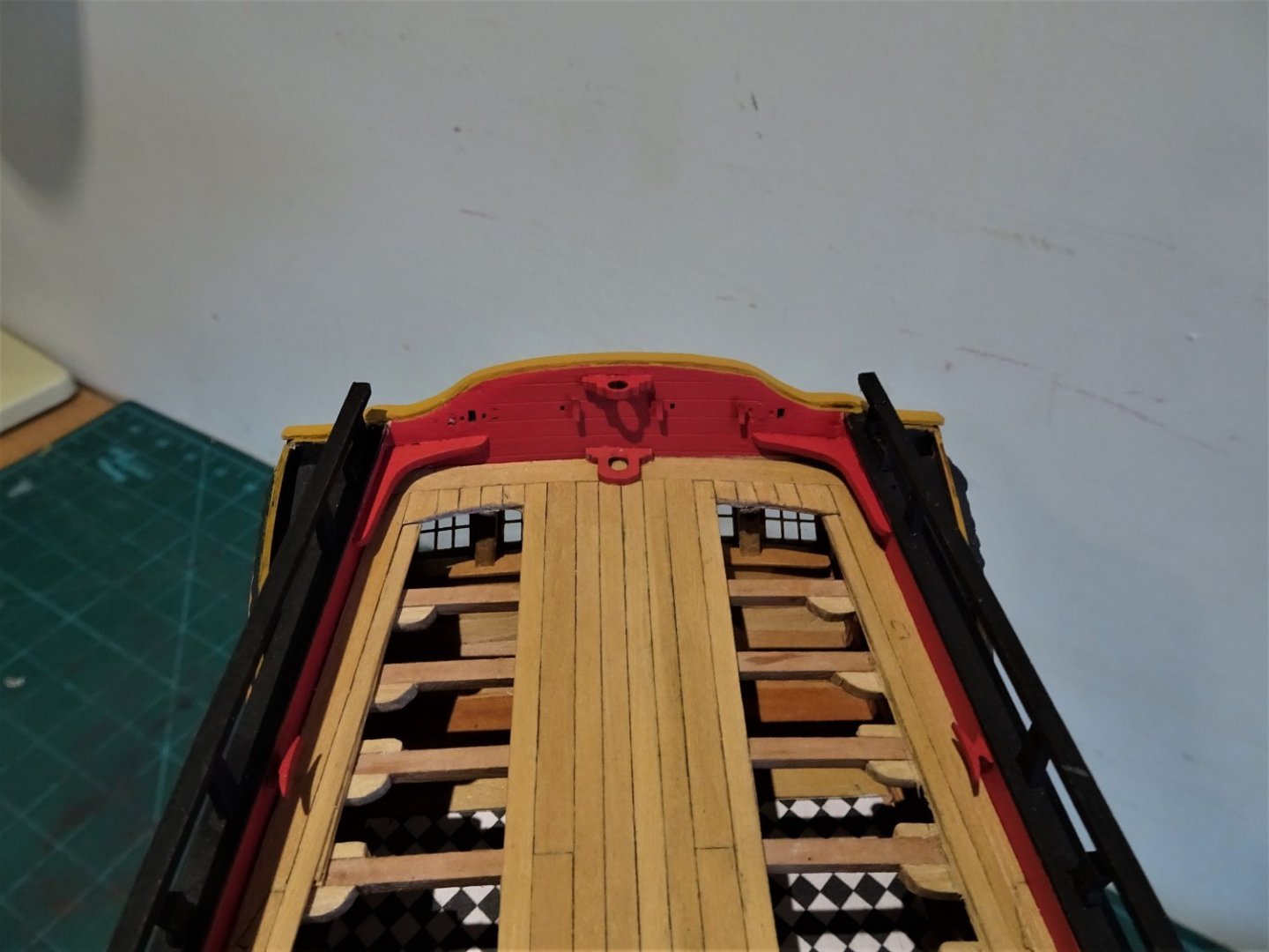
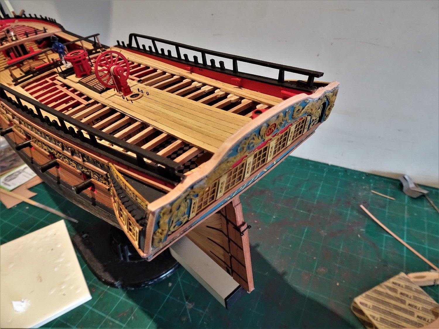
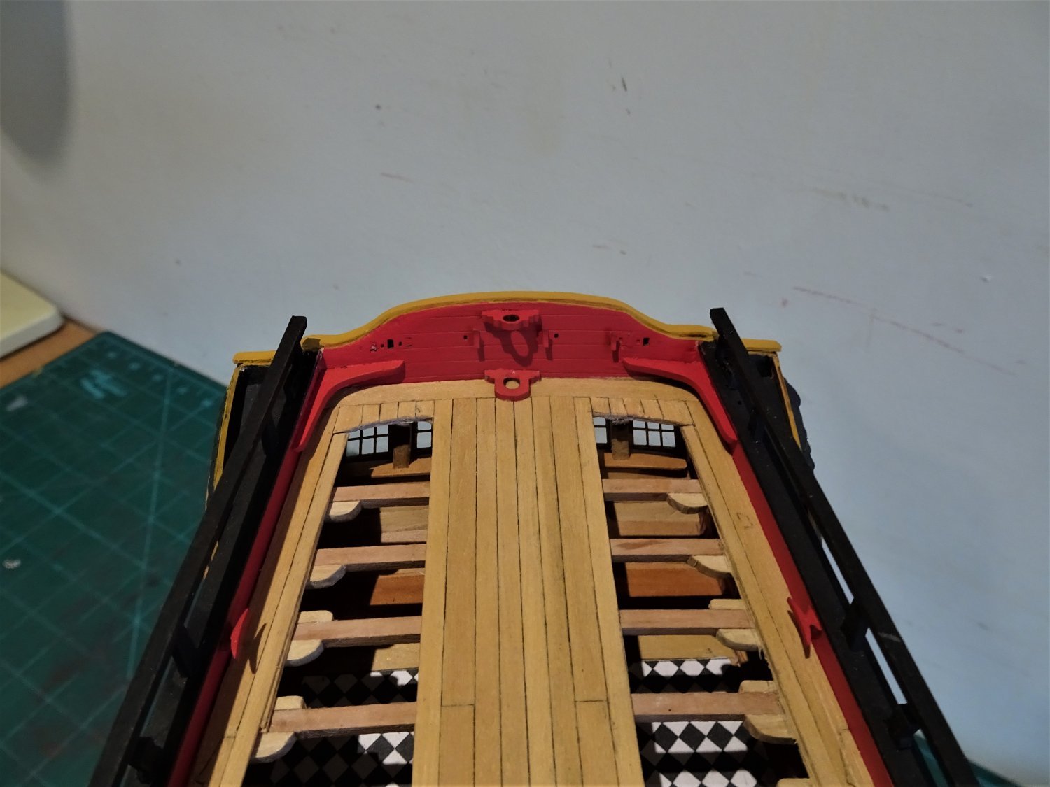
Post One Hundred and Twenty-eight Taffarel Capping rail. The kit Taffarel is a three piece lamination which is difficult to mask, and should properly have a capping. On Pegasus I made a capping rail using Evergreen styrene strip which is easy to mould to the shaped top, and the medium is not an issue as the rail was to be painted. With Sphinx I used 0.8mm x 3mm Pear strip, well soaked, and clamped into place on a spare Taffarel piece to form the shape. 7159 Ca was used to glue the capping progressively along the Taffarel top. 7160 It took a while to get the ca to hold, and there was the inevitable need for micro filling and re-touching of the facia. 7169 I originally painted the rail Ochre brown, which looks brighter here than it actually is. 7170 … but against the red of the inboard Taffarel it didn’t look good, a bit like raspberries and custard. 7180 I changed the colour to black to match the other cappings. 7185 A lot of re-touching the paintwork followed, followed by more re-touching, followed by more… you get the idea. 7186 There are many opportunities to go off-line when painting the fine detail, the cold eye of the macro lens reveals all. I work towards the point that when wearing my specs from a viewing distance of around 10” nothing untoward catches my eye. 7182 Of course I am a founder member of the Blind man on a galloping horse school of model painting, so others may see things hidden to me. 7176(2) Moving onto the Channels. B.E. 04/06/2022


.thumb.JPG.bd48ef9067ca5b1d15b32d330be1e082.JPG)


- 857 replies
-
- 22
-
-
- Sphinx
- Vanguard Models
- (and 1 more)
-
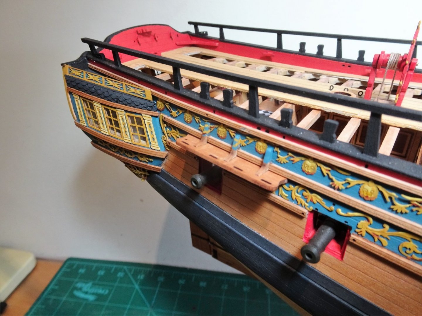
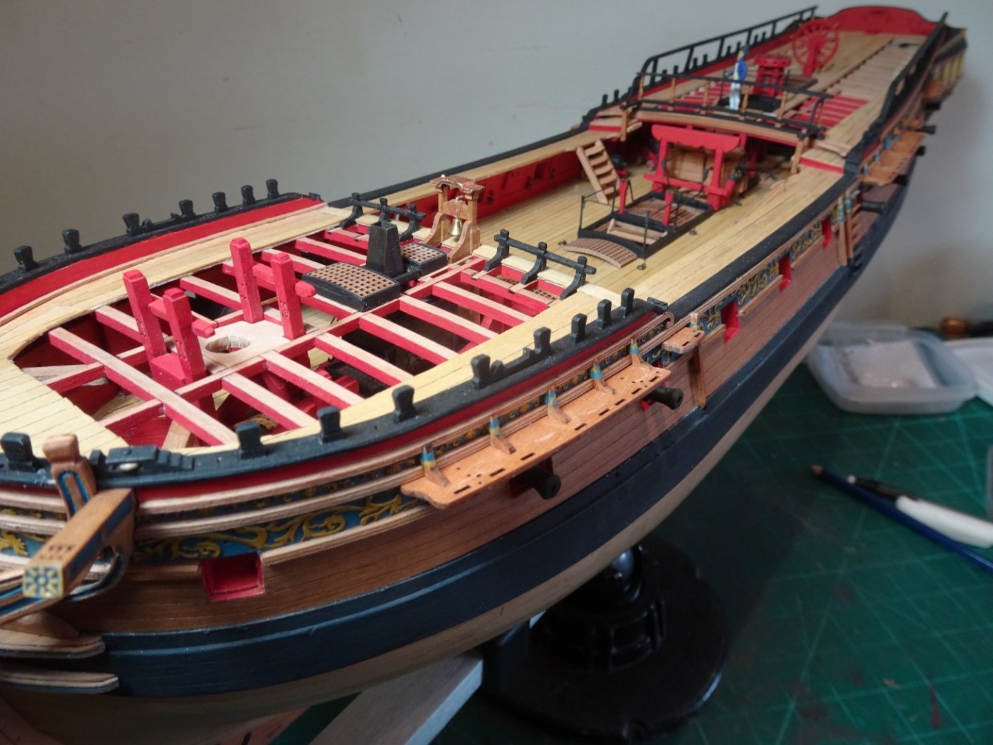
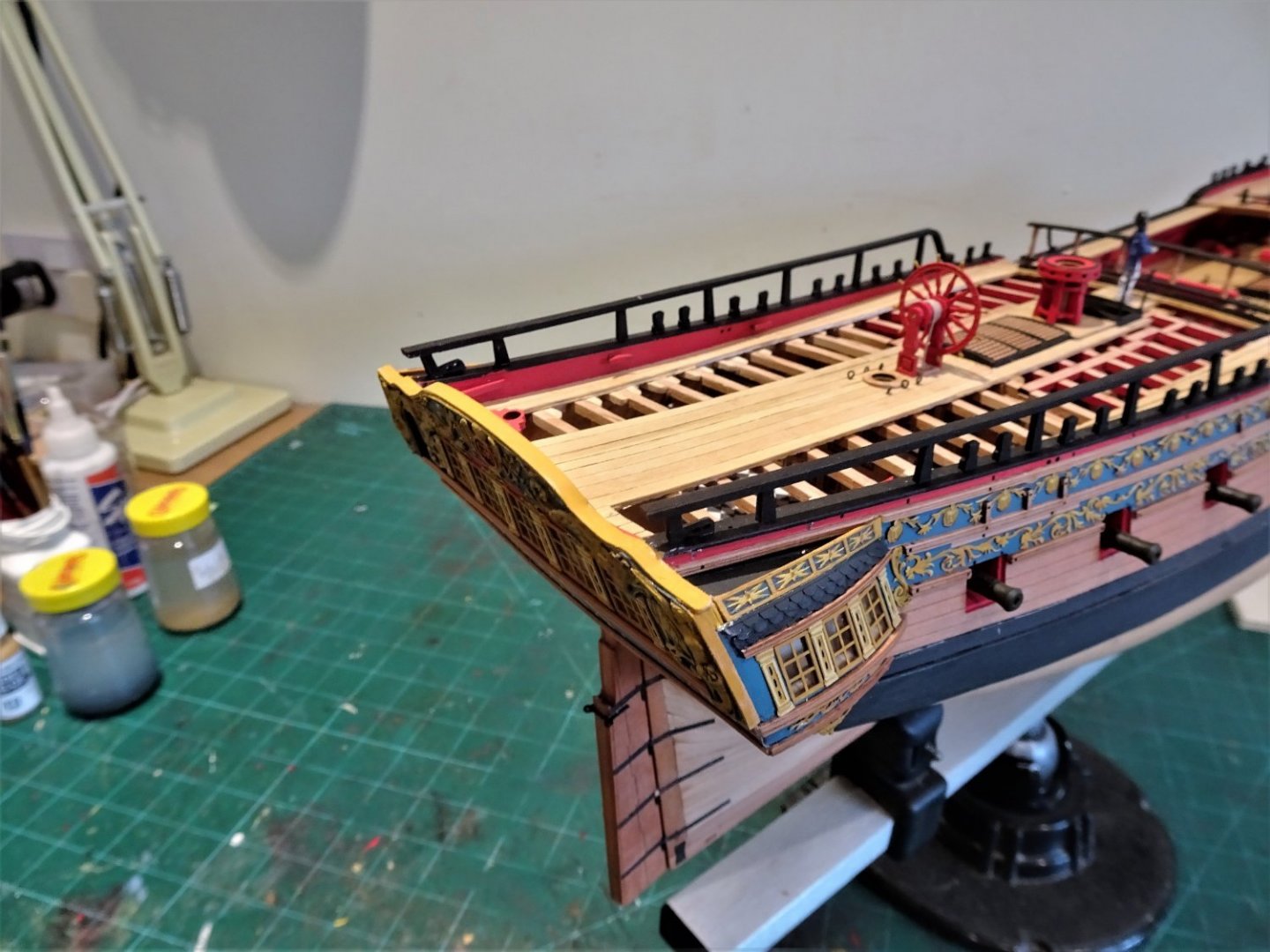
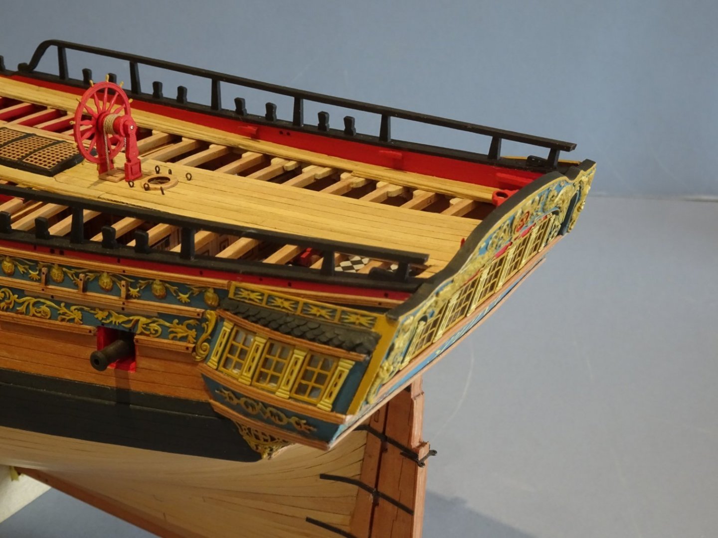
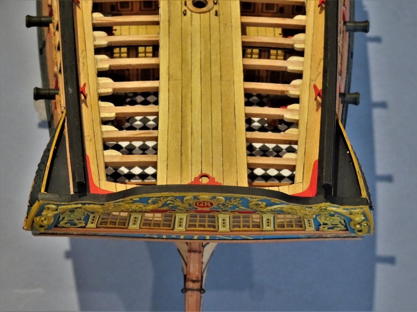
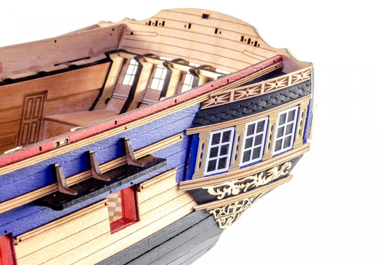
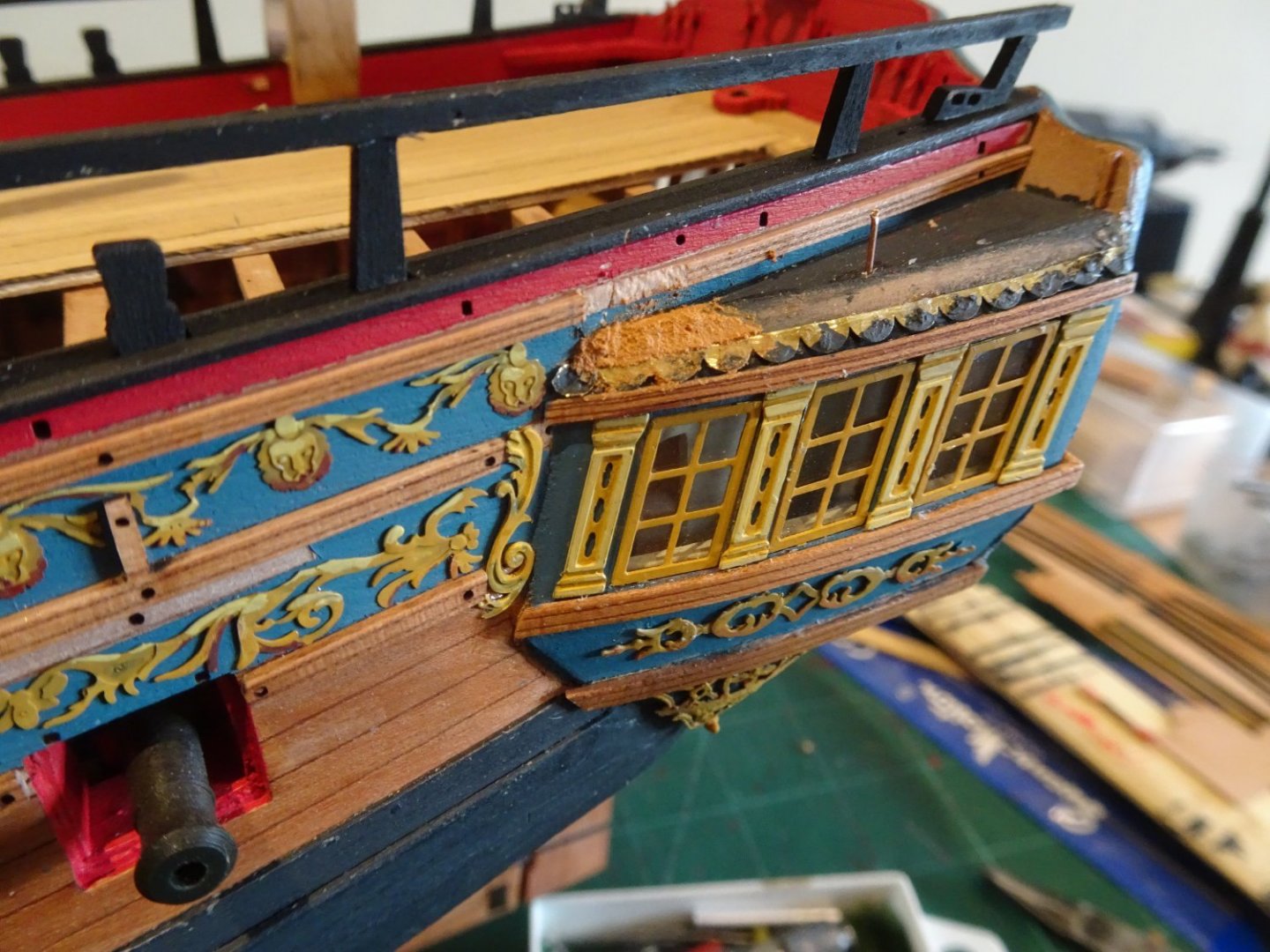
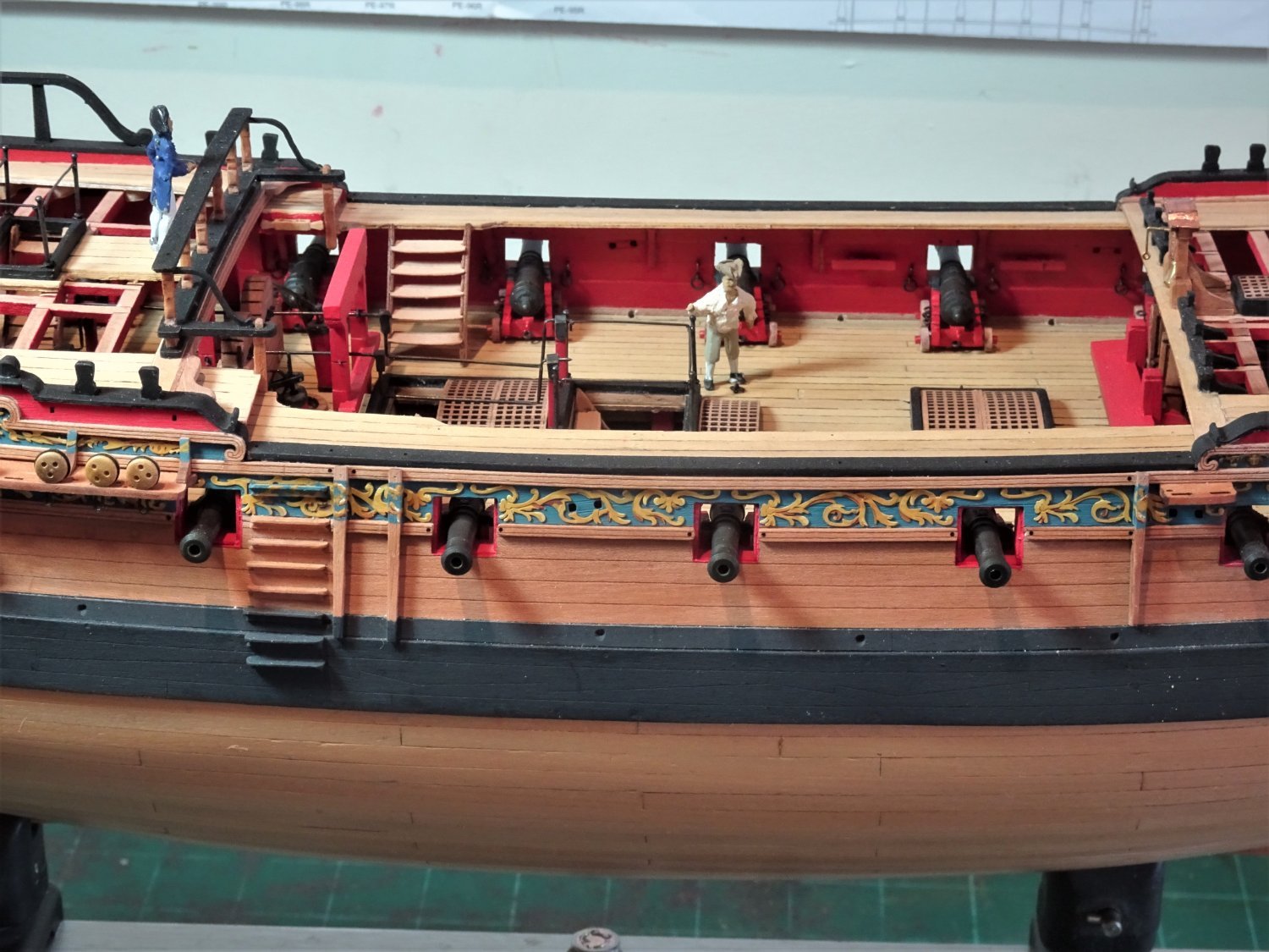
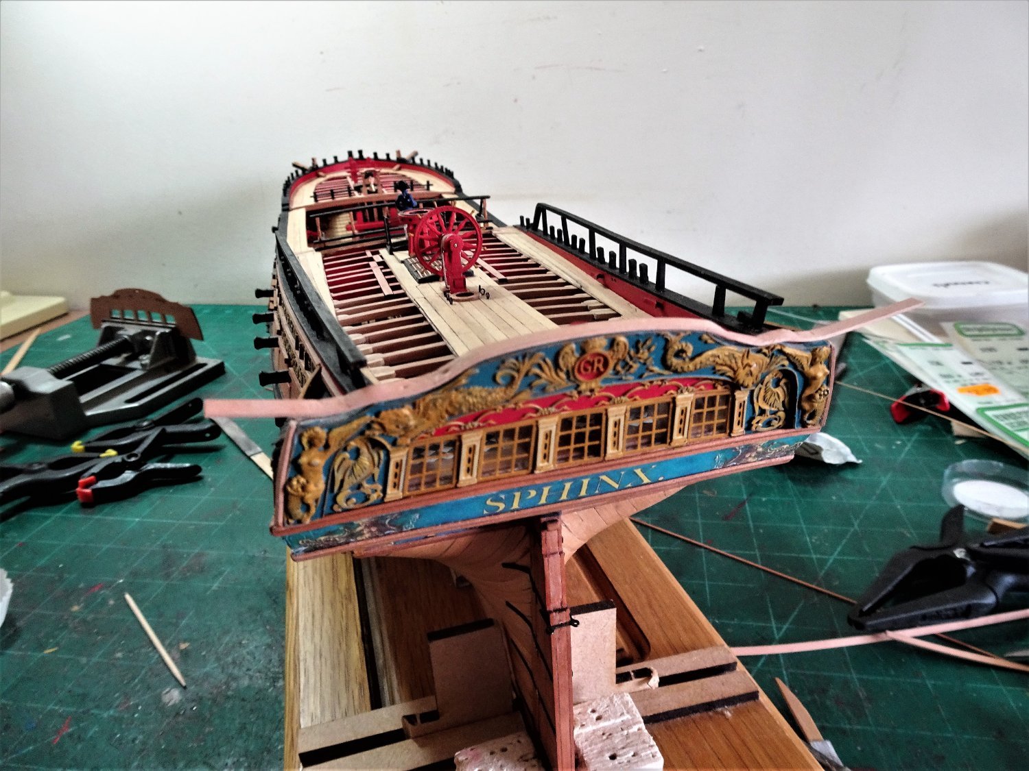
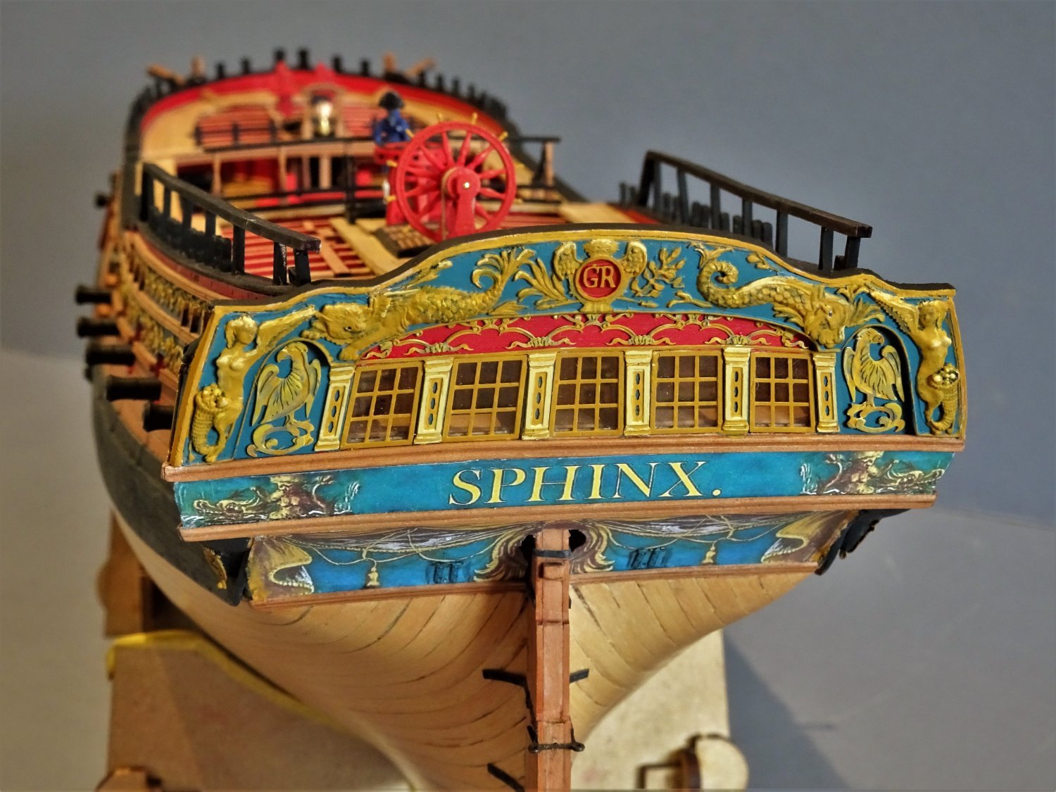
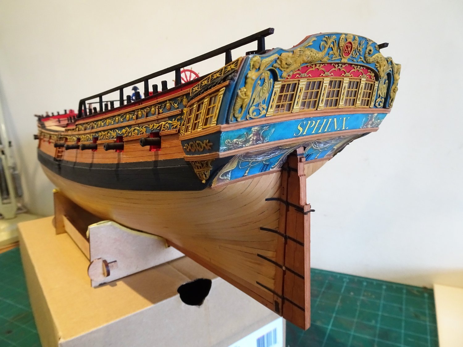
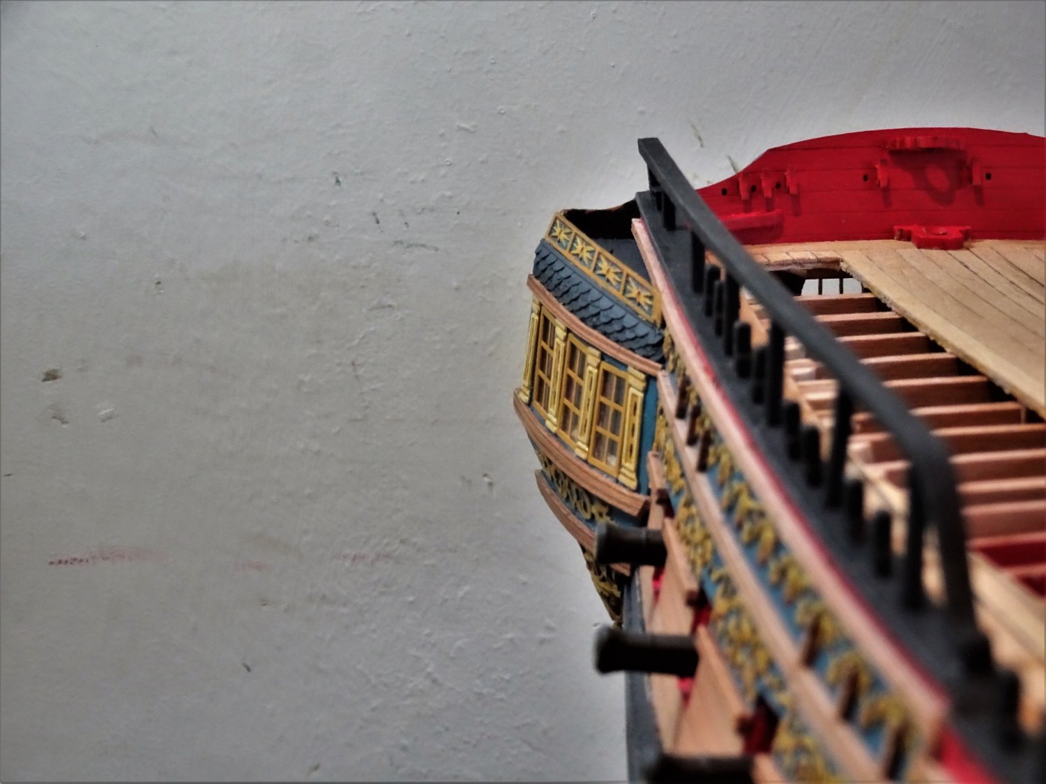
Post One hundred and twenty-seven Quarter Gallery Decorative roof rail. Before I move onto the channels I have decided to attend to the Quarter gallery roof rail, described in the kit blurb as the Upper Fretwork. Before any fitting work or even removal from the fret the piece is painted to match the colour scheme. I was slightly puzzled by the fit of these decorative pieces; one end has a wider section than the other, which I took to be the forward end. I note on the prototype build photos that the forward end has been trimmed to sit below the decorative upper rail. 319 Beautifully fitted but I didn’t think the cut-away arrangement looked quite right, and it didn’t match the arrangement on the plan. To address this, a small section of the decorative upper rail on the hull was removed. The roof rail needs to be curved to match the contour of the Gallery roof. 7134(2) To this end I used the spare mdf gallery blanks as formers to heat bend the pieces. A piece of fret was used to provide a support against the tafferal, and a metal support pin was used centrally to keep the rail in line with the roof contour. The forward end of the roof rail fayed into the space in the decorative rail. The bottom of the finishing piece was bevelled on the underside to give a slight inward inclination. With all the trial fitting and handling the pieces required repainting before fitting. As with many things during a build one side fits easily, the other a struggle. 7154 7139(2) 7143(2) Fitting the Starboard roof rail went without issue, but a problem was quickly revealed on the Port side. The problem being that my shaping of the roof top was too severe at the forward end resulting in the rail not sitting correctly atop the shingle roof line. Incidentally I was pleased to see that Chris has replaced the brass etch tiles on his new Indy kit with laser cut card, I wish I had had them on Sphinx. The tiles were removed and the roof line adjusted using filler to build it up. Annoying to have had to back-track but the repair will be hidden by the shingles. 7137 This photo shows the filler build -up, the support pin, and Tafferal support. 7147(2) Port side restored. I'm not entirely sure that I like the solid look of the roof rail, nor particularly the results of my efforts. I think an open fret rail would have been a better fit for this decorative item. I'll leave it a while but I may have to re-visit the whole roof set -up. 7145 There is still some work to do on the stern, a capping rail to be fashioned, and one or two bits and pieces to tidy up. B.E. 02/05/2022
.thumb.JPG.a09bd948a73b1c3157a9b430781a4265.JPG)
.thumb.JPG.375498eddc9265bea801d7464d2f61ee.JPG)
.thumb.JPG.7ca3dce5e3def0daab70c7e64470358c.JPG)

.thumb.JPG.a1dad9dfe47b804b07b7207959216817.JPG)

- 857 replies
-
- 22
-
-
- Sphinx
- Vanguard Models
- (and 1 more)
-
Looking good Glenn, and by fitting the first few Ratlines at intervals certainly helps to counter pulling the shrouds out of line, it's the method I use for 'Rattlin' down. B.E.
- 476 replies
-
- 3
-
-

-
- sphinx
- vanguard models
- (and 1 more)
-
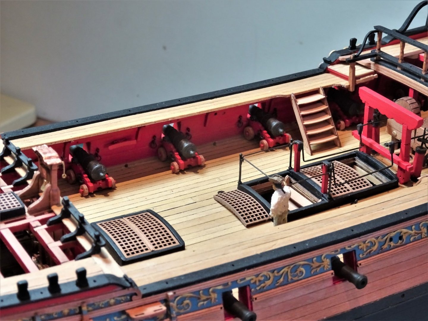
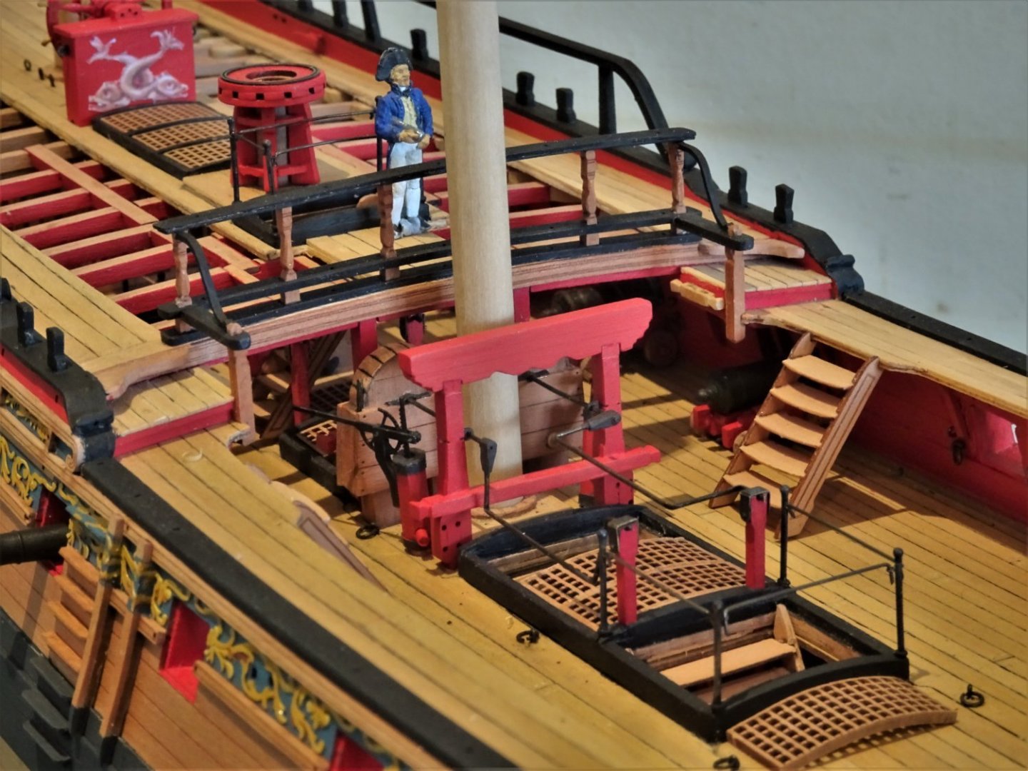
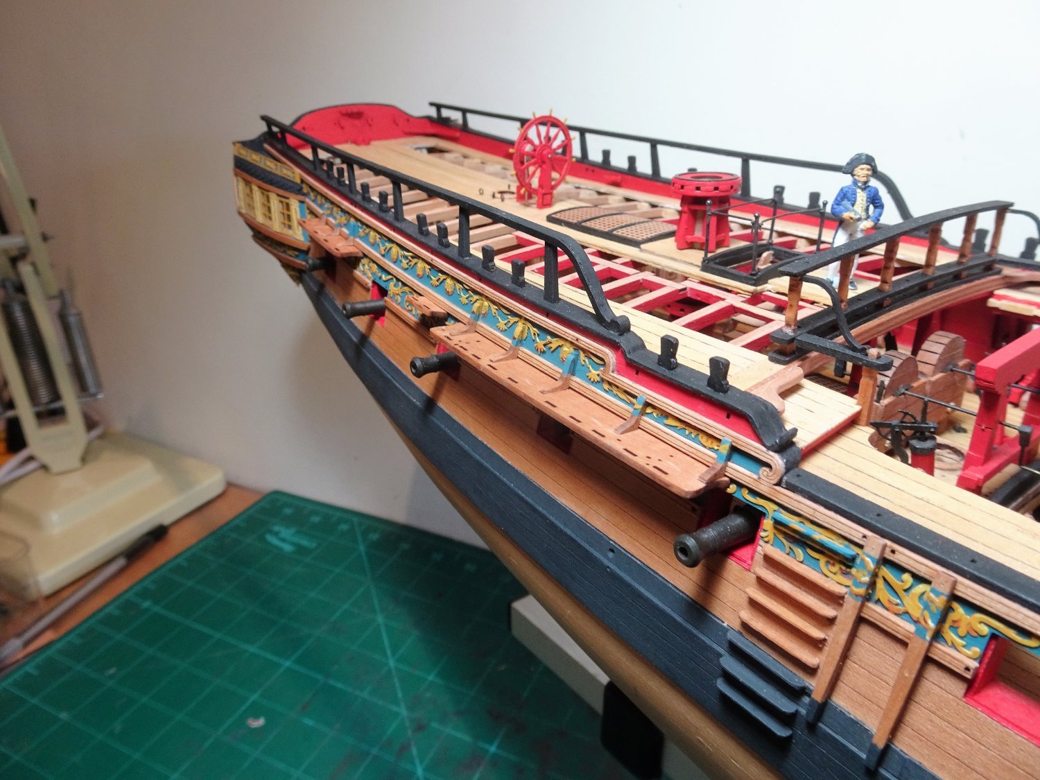
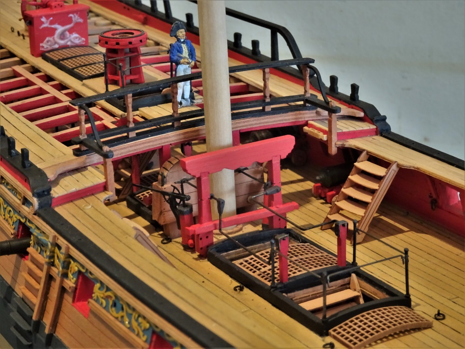
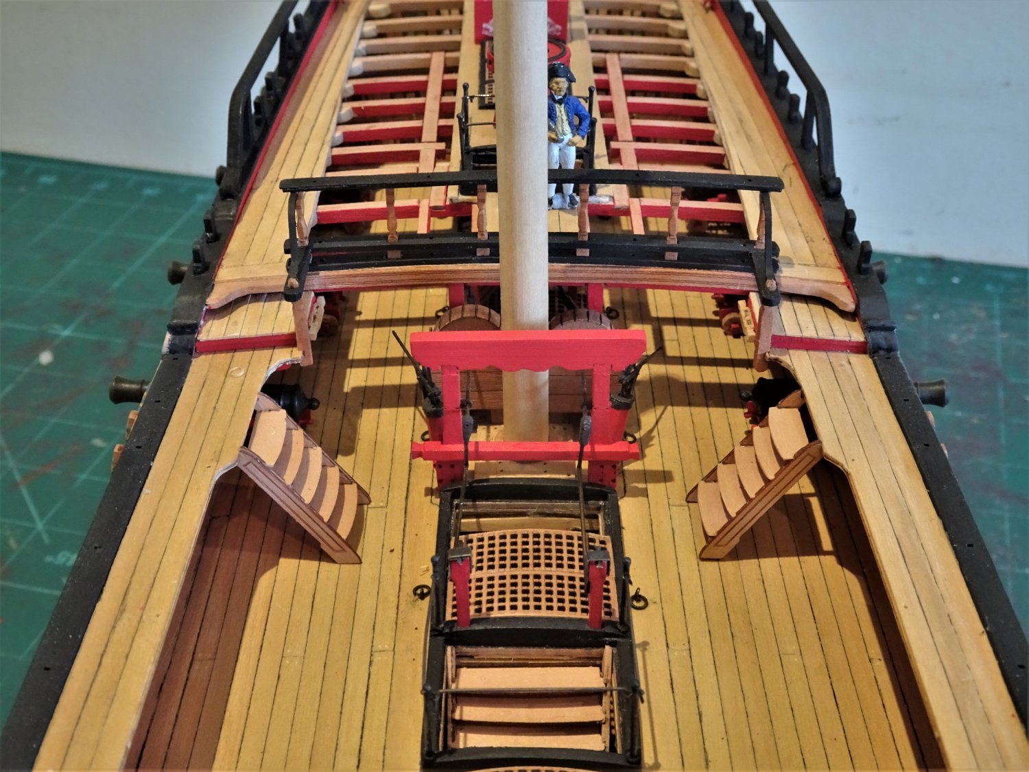
Post One hundred and twenty-six A final push on the Gun wharf Before I started, an annoying set back. In a moment of carelessness faffing around with the model for my last photo shoot I dislodged the rudder breaking off three gudgeons from the stern post. On reflection perhaps I shouldn’t have questioned those boom rings in my last post, some sea devil has created a need for them.😕 Even manoeuvring a model the size of Sphinx has its dangers, God knows how I would get on with a beast like Indy on my 24” deep work bench. I have form for concentrating so hard on the job in hand that I swing the model around without checking the proximity of obstacles, usually the wall.🙄 Re-hanging a rudder is a pleasure I could have done without. I knuckle down to assembly of the remaining guns. There seems an awful lot of char removal in eight guns but it has to be done. 7112 The barrels are washed and sprayed with fixative after which weathering powders are applied and brushed off. 7114(2) For the last time with Sphinx I set up my production line. I find I have run out of Amati fine copper eyelets that I use for the loops, and in combination with Amati 2mm brass rings for the breeching ring bolts. I only have sufficient makings to complete two guns but at least these can be used to fit beneath the Gangway which will allow me to complete the Ladders down to the Upper deck. The remaining six guns will have to wait until fresh supplies arrive from CMB. 7122 I amuse myself assembling the ladders – nicely shaped but a pain in the Orlop to put together. 7121 7124 I may well include cut off masts. But they won’t look like these place holders. Time to look at the Channels I think. B.E. 01/6/022
.thumb.JPG.e5ae8f920a22c828bf0ff6da7e4c0319.JPG)

.thumb.JPG.31e73ec9e3325b29e7af440a380f0d09.JPG)
- 857 replies
-
- 27
-
-
-
- Sphinx
- Vanguard Models
- (and 1 more)
-
Another fine Duchess, very nicely done David. B.E.
-
Chris has such a knack of producing pretty models, and you have built a fine example that surely must encourage sales. Beautiful work as always Rusty.👍 B.E.
- 201 replies
-
- 3
-
-
- Duchess of Kingston
- Vanguard Models
- (and 1 more)
-
I do love to see beautiful headworks befitting an amazing model, your attention to detail and effort to achieve the best it can be mark you out as someone special in the world of model ship building. Thank you Chuck. B.E.
- 1,784 replies
-
- 3
-
-
- winchelsea
- Syren Ship Model Company
- (and 1 more)
-
Hi Glenn, re the Mizen Catharpins: Lees mentions use of these on the Mizen, but they are not included on the rigging plan for Pandora (AotS) nor do they appear in Steel's rigging tables for vessels rated 20 -24 guns. If you decide to keep them consideration needs to be given how they may impact when it comes to fitting and rigging the Gaff. B.E.
- 476 replies
-
- 3
-
-
-
- sphinx
- vanguard models
- (and 1 more)
-
What you say is a standard approach OC what I'm saying is gentle handling is required with these parts, any breakages can create problems with the built in camber. B.E.
- 505 replies
-
- 7
-
-
- vanguard models
- Sphinx
- (and 1 more)
-
Coming along nicely Mark, Be careful with the deck beams when trial fitting and cleaning, the slots for the carlings are a weak point, as are the slots on the ends to fit along the bulwarks. Slow and steady is the way to go. B.E.
- 505 replies
-
- 5
-
-
- vanguard models
- Sphinx
- (and 1 more)
-
Looking good Peter, very nice work. Love the second shot in the sequence, did you know there appears to be a hobgoblin lurking at the head.😉 B.E.
- 366 replies
-
- 2
-
-
- bellerophon
- victory models
- (and 2 more)
-
Thank you Derek, Bob, and Ron, and for those who follow and ‘like’ my build. @ Derek - You’re very kind, but I’m not sure where I would put such a beast as ‘Indy’ I do have Chuck’s Medway Long boat beneath my bench, ½” scale for my tired old eyes, and beautiful Boxwood timber. Regards, B.E.
- 857 replies
-
- 4
-
-
- Sphinx
- Vanguard Models
- (and 1 more)
-
Duchess is looking wonderful, Derek, I do love the look of Boxwood, I much prefer it to Pear. An impressive workspace you have there, makes mine look cramped by comparison, and as for David's (desalgu) Mrs W happened to spot it and I'm now under the cosh to tidy things up. (Great looking aircraft by the way) Cheers, B.E.
- 345 replies
-
- 4
-
-
-
- Duchess Of Kingston
- Vanguard Models
- (and 1 more)


.JPG.ae79587a3d4ca1d282ff39204111cc0c.JPG)
.JPG.1112dcf5cd5d4dadf50f3c86a9ca1ff0.JPG)
.JPG.f6e766ec97aca5dac44c062ba27021c0.JPG)
.JPG.562098cea5ef9a1f9baeb2dab66b32bb.JPG)


.JPG.f6612ddb965aa40ea13955cf53eba533.JPG)
.JPG.a1d0cbbcf6c6abdb88ab97bd36222705.JPG)


.JPG.fa59bc9c388b3e7ea05121bc5b341556.JPG)
.JPG.0277029bb9049bce53f7551a5251188a.JPG)

.JPG.998a38ebeaa99157684b15c8341b3d13.JPG)


.JPG.2f566838f8f19dd9c70238c73d24e55e.JPG)

.JPG.7313399a966d154a86286f27bd1fc44f.JPG)
.JPG.e370bd7ae4464c1b48bf797bfd01d28f.JPG)
.JPG.23d397c03edc5e83164ceaffd111d3bd.JPG)

.JPG.84def5e356ba8ad0c6ffbfdf87974da0.JPG)
.JPG.008a33bc6f66c044e1bfc264640e70f7.JPG)