.JPG.ca33079f5815b861e67b9c2cccd37982.JPG)

Blue Ensign
-
Posts
4,572 -
Joined
-
Last visited
Content Type
Profiles
Forums
Gallery
Events
Everything posted by Blue Ensign
-
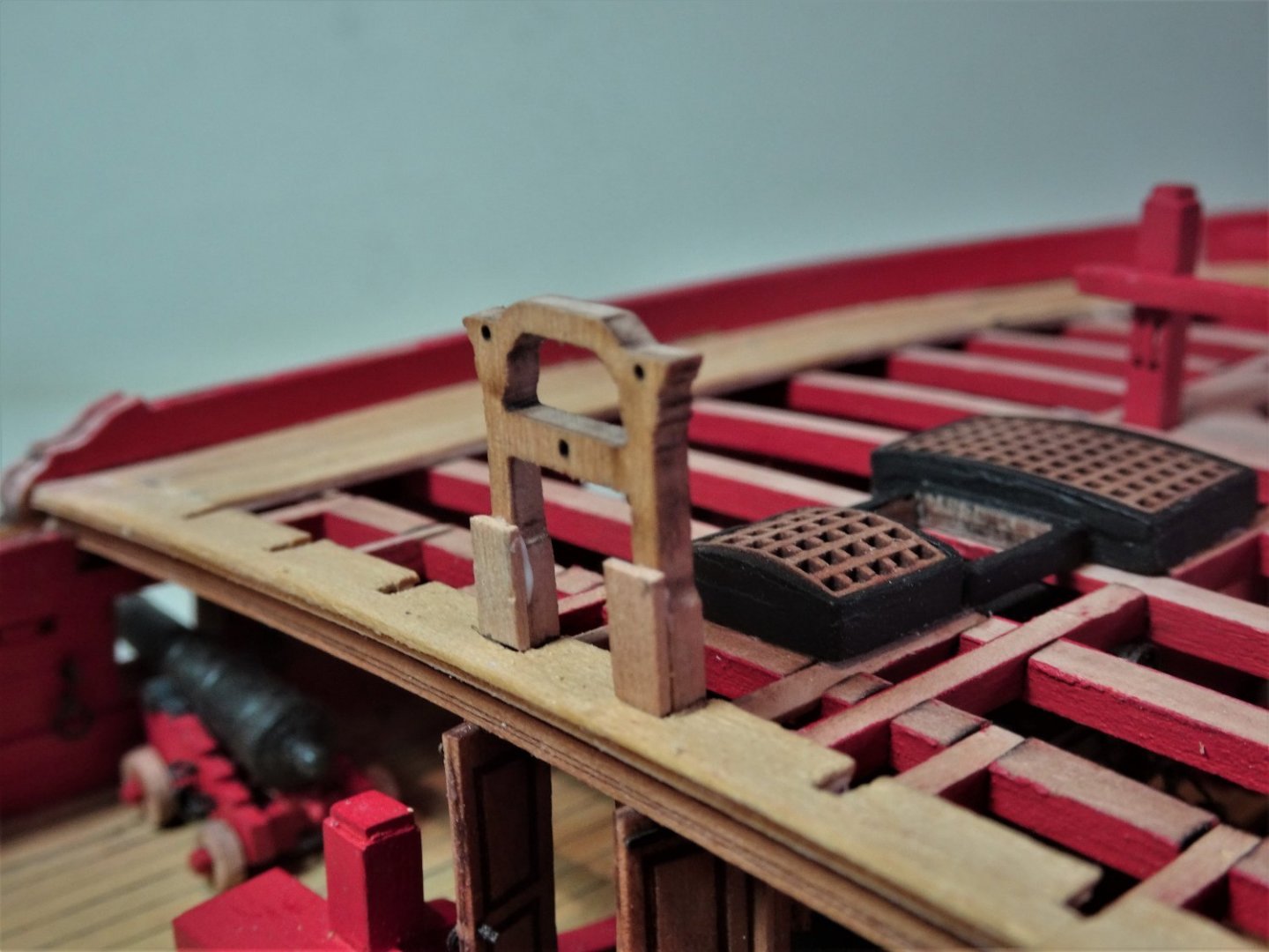
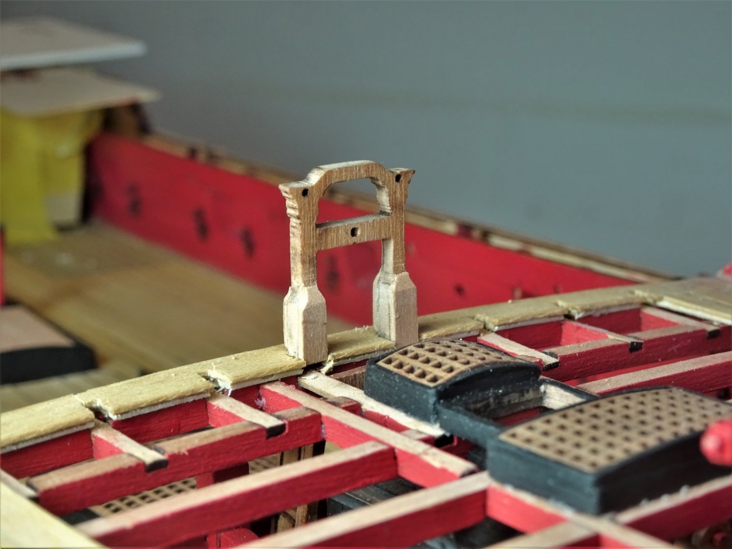
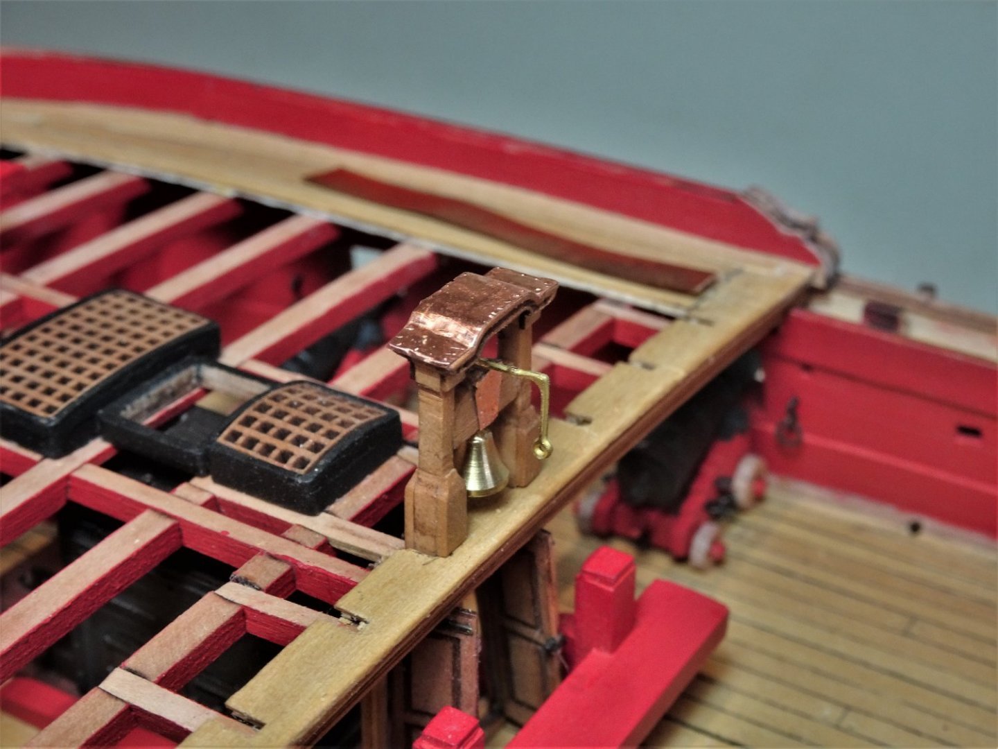
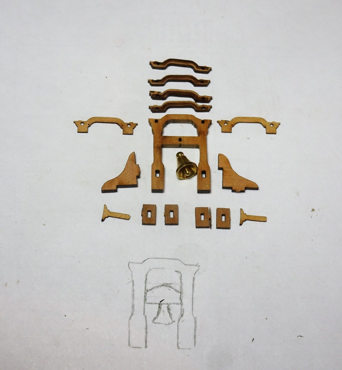
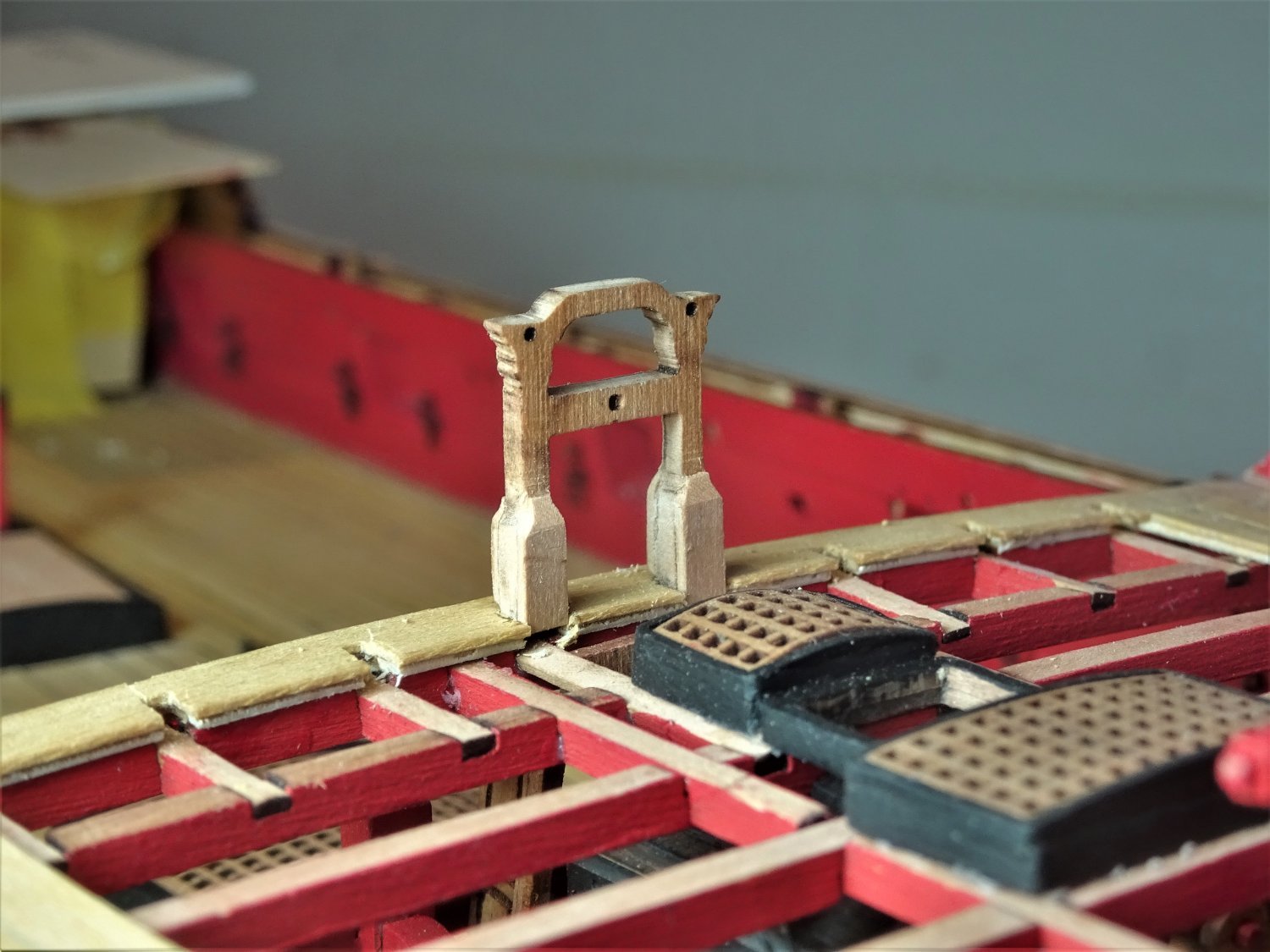
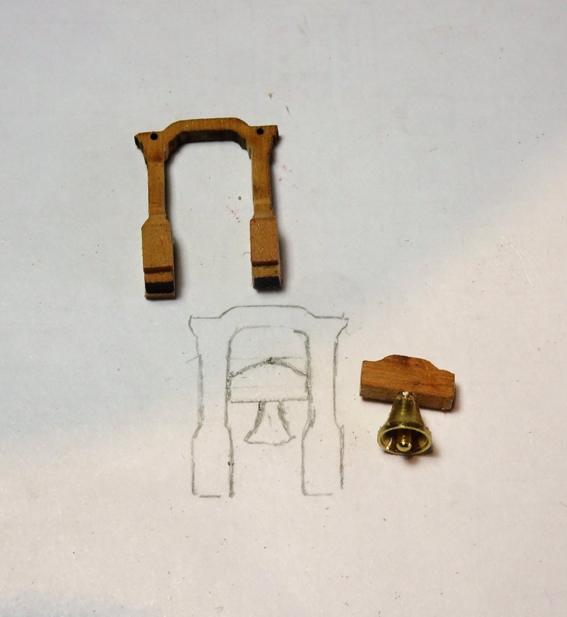
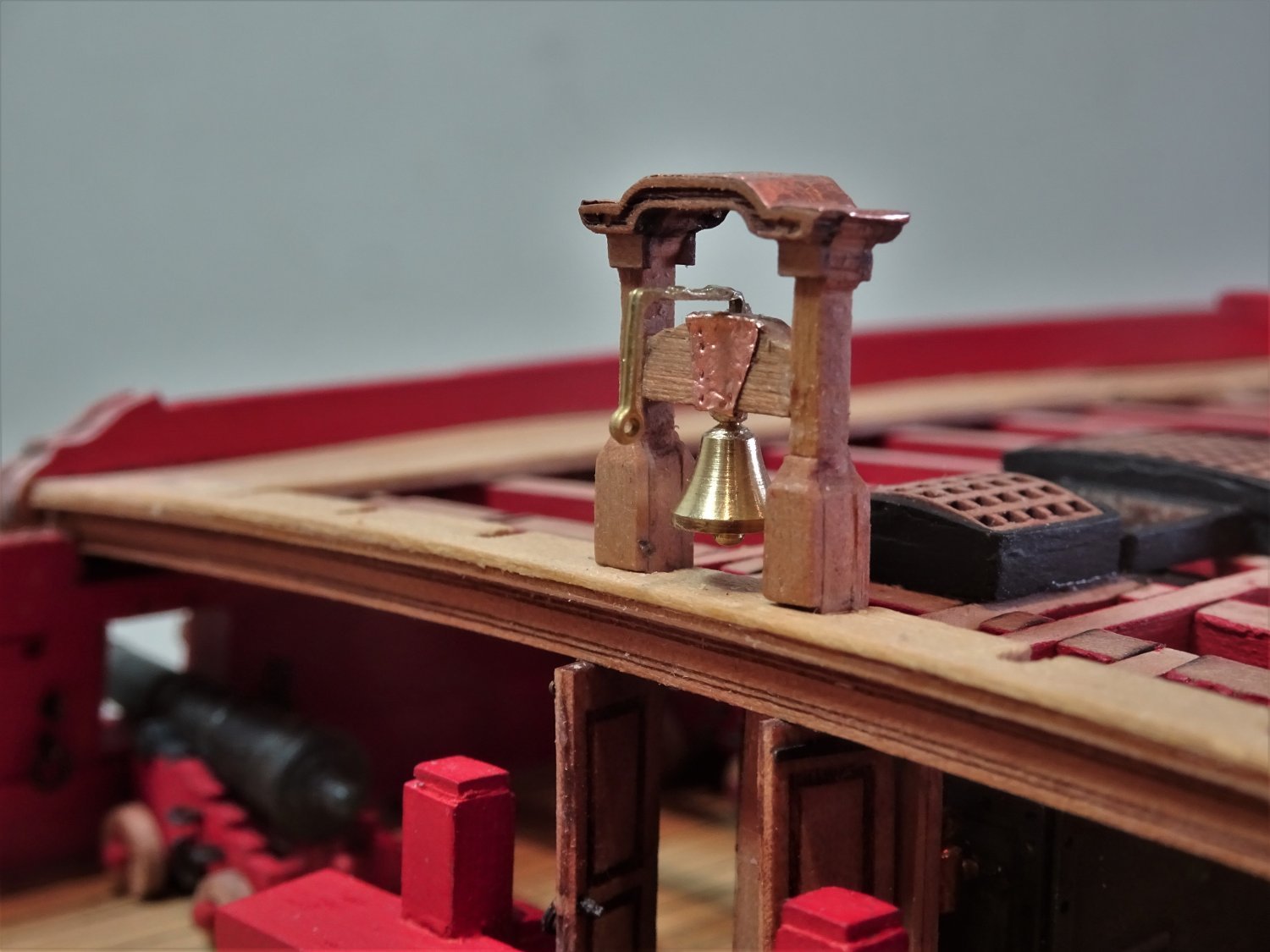
 Post One Hundred and nine Foc’sle fittings. Belfry. I have been looking forward to assembling this important feature on a ship model. 6496 This is a laser cut assembly of multiple delicate parts. In cleaning the char, I used very soft hands and a mini vice to prevent any flex during sanding. As I intend to leave the Belfry bright good cleaning is essential to show the Belfry at its best. The Belfry on my Pegasus build is a little fancier than that supplied with Sphinx, and I can’t really let a sixth-rate sloop outshine a ship rated for a Post Captain. On my build there will be little around the Belfry to distract the eye so there are enhancements that can be made and one that should be made. The basic main patterns and canopy look fine, but I feel the supplied lower support patterns let the structure down. To my eye they look ugly and very obviously stick-ons, lacking the elegance of the Classic design employed during the 18thc on this feature. The Headstock can be tweaked to a more stylish shape. A crank arm can be added. There is very little brightwork on my version of Sphinx, so I have indulged myself a little with the Belfry. As with Pegasus I intend to copper the Canopy roof, this will have the additional benefit of masking the layered assembly. I’m not sure what the purpose of the two cleats on the aft face of the columns are for. On Pegasus two cleats are shown on the sides of the columns, indicated for the Fore T’gallant braces belay. For Sphinx these are indicated belaying at the Foc’sle rail. 6497 I begin by replacing the lower support patterns, using 3mm x 0.8mm Pearwood strip to build up the base of the column fore and aft to reflect the chamfered pattern of the athwartships design. 6500 This instantly improves the look of the columns. A shaped Headstock is cut from some 2mm thick Pearwood fret. 6507 The pattern cross bar is cut away from the Main pattern (scary) and replaced with a more stylish version. The bell fits into the base of the new Headstock. The Bell is quite a nicely modelled Brass item. 6512 A Crank arm is formed using an old Hammock crane and fits into the top of the Headstock. 6516 Finally, the Canopy top is coppered using some copper foil tape also used for a representation of the metal strapping on the Headstock. Still some fettlin’ to do and the support knees to add but overall I’m pleased with the result. B.E. 14/04/22


- 857 replies
-
- 22
-

-

-
- Sphinx
- Vanguard Models
- (and 1 more)
-
Have IPSFocus been playing around with the Theme display? Mine suddenly went into a strange linear display with oversized logos, virtually unusable on a desk top monitor. It seems that it is what they call the default mode, and to get anything recognisable the option is 'Uniform' which sort of looks like my old preference. My old display theme. Anyone else experiencing this, you need to scroll to the bottom of the page and change the selection in 'Themes' B.E.
-
Post One hundred and eight Snaggins. Not for the first time I take a backward step and start ripping up the work I did the day before. Why I didn’t stop when I sort of knew the colour match wasn’t ultimately going to satisfy my eye I don’t know, a case of hope over experience perhaps. It is not that difficult to remove planking without disturbing the adjacent planks. Dampening the strake and easing using a thin blade they can often be removed intact. 6470 6472 6473 Another day to rectify what I should have done in the first place but I am now happy with the colour match. Movin’ on. B.E. 12/04/22


- 857 replies
-
- 28
-
-
-
- Sphinx
- Vanguard Models
- (and 1 more)
-
Thank you Nipper, very kind of you to say so. B.E.
- 857 replies
-
- 1
-
-
- Sphinx
- Vanguard Models
- (and 1 more)
-
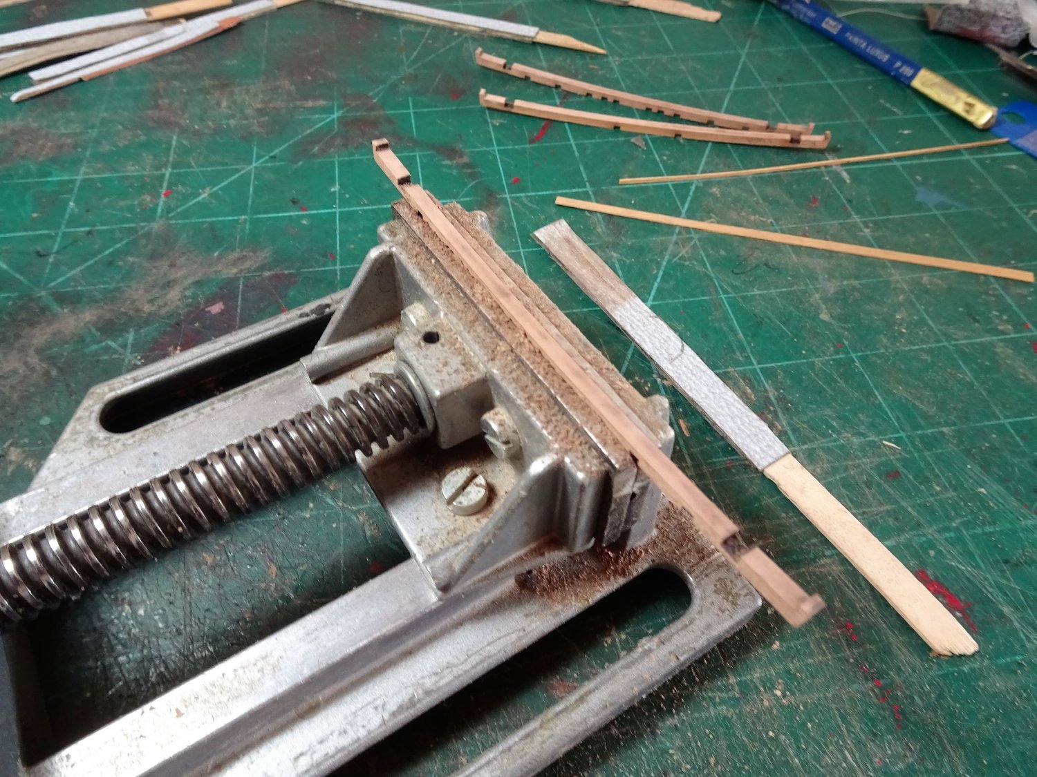
Post One Hundred and seven Completing the Foc’sle planking. The inner bulwarks patterns were put into place following the kit blurb. The Cathead slot was then cut to match the outer bulwarks. The Margin planks proved stubborn with initial attempts thwarted when the planks broke at the cross grain of the sharp curve. This was addressed by the simple expediency of applying sticky backed labels to the underside of the strip before cutting. With the margin strips fixed the thin bulwark skins were glued into place. At this point the decks were covered to hopefully limit as far as possible sanding dust dropping to the lower decks. 6413 The bulwarks are sanded level, but I had the Foc’sle gunwales handy to check progress. There are only three strakes of planking along the bulwarks. This involved a couple of hooded planks, as nibbing was not a general feature of this period. 6419(2) Forming a hooded plank, cut out of 10mm strip and edge bent slightly to match the margin. Planking completed, but it will require scraping and sealing. 6457 6456 6451 6453 6450 Still a fair bit of fettlin’ to do and more stuff to add. I am thinking about removing the three paler hooded planks and try to find a better colour match. They keep catching my eye in an annoying sort of way. B.E. 11/04/22

.thumb.JPG.5e069cc243430a4e5bb46d73509aff80.JPG)
- 857 replies
-
- 22
-
-
-
- Sphinx
- Vanguard Models
- (and 1 more)
-
Slip of the tongue Allan, I meant of course the lodging knees. B.E.
-
'Although they will be completely hidden! ' Not on my build they wouldn't 😉 Sounds like the best approach with those below deck guns.👍 B.E.
-
Looking impressive Chris, I'm pleased to see you have included the ledges with the deck beams, nice touch. 👍 Are the gun carriages the same style as Sphinx with the built in cap squares? I like the system but it does prevent pre drilling the carriages and decks to take securing pins. Just thinking of ways to secure the numerous guns below decks. Those lower deck guns will be in position fairly early on in the build, with a lot of handling of the hull to follow with the inherent risk of dislodgement. Regards, B.E.
-
Thank you Dave, Syren do a 1.4mm and 1.6mm ø line, and I see that Ropes of scale do a cable laid line in 1.3. 1.45, and 1.6mm diameters. I often find that the calculated line size doesn’t sit quite right with my eye on the model, so I always let my eye be the final arbiter, and I tweak the size to suit. I usually buy a couple of sizes around the indicated size, and pick the one I like best. B.E.
-
Just knew you would say that Bug, 👍 what else should I expect from a guy who knits his own netting. 😉 B.E.
- 419 replies
-
- 5
-
-

-
- Victory Models
- Pegasus
- (and 2 more)
-
I don't think so Alan, circumference meant circumference, and line dimensions were always given in inches circumference. We model makers tend to work in mm diameter or fractions of inches diameter in relation to model line as that is how it is supplied. All we need to remember when using contemporary records is to divide the given circumference by 3.142 before doing the scale calculation. B.E.
-
Hi Dave, Have a look at Post 70 on page eight of my cutter Alert log. It details how I worked out the anchor cable size for a cutter at 1:64 scale, and how the given formulas compared to the kit given sizes and those given in the Aots book on Alert. Hope this helps. B.E.
-
Nice looking bees Moon, and I admire your persistence and result with the rope netting for the waist rails.👍 On the question of the Bowsprit cap did you allow for the Jack staff, I can't quite tell from the pics? B.E.
- 419 replies
-
- 4
-
-
- Victory Models
- Pegasus
- (and 2 more)
-
Thank you Ron, what you see is only a temporary building board. I favour displaying the model on keel blocks which will be fitted within the case that I already have for her, but that’s a while away. Regards, B.E.
- 857 replies
-
- 1
-
-
- Sphinx
- Vanguard Models
- (and 1 more)
-
That is quite some project Chris, and looks so good even in macro. Must require a lot of concentration working on such fine parts, very nice work. B.E.
- 331 replies
-
- 14
-
-
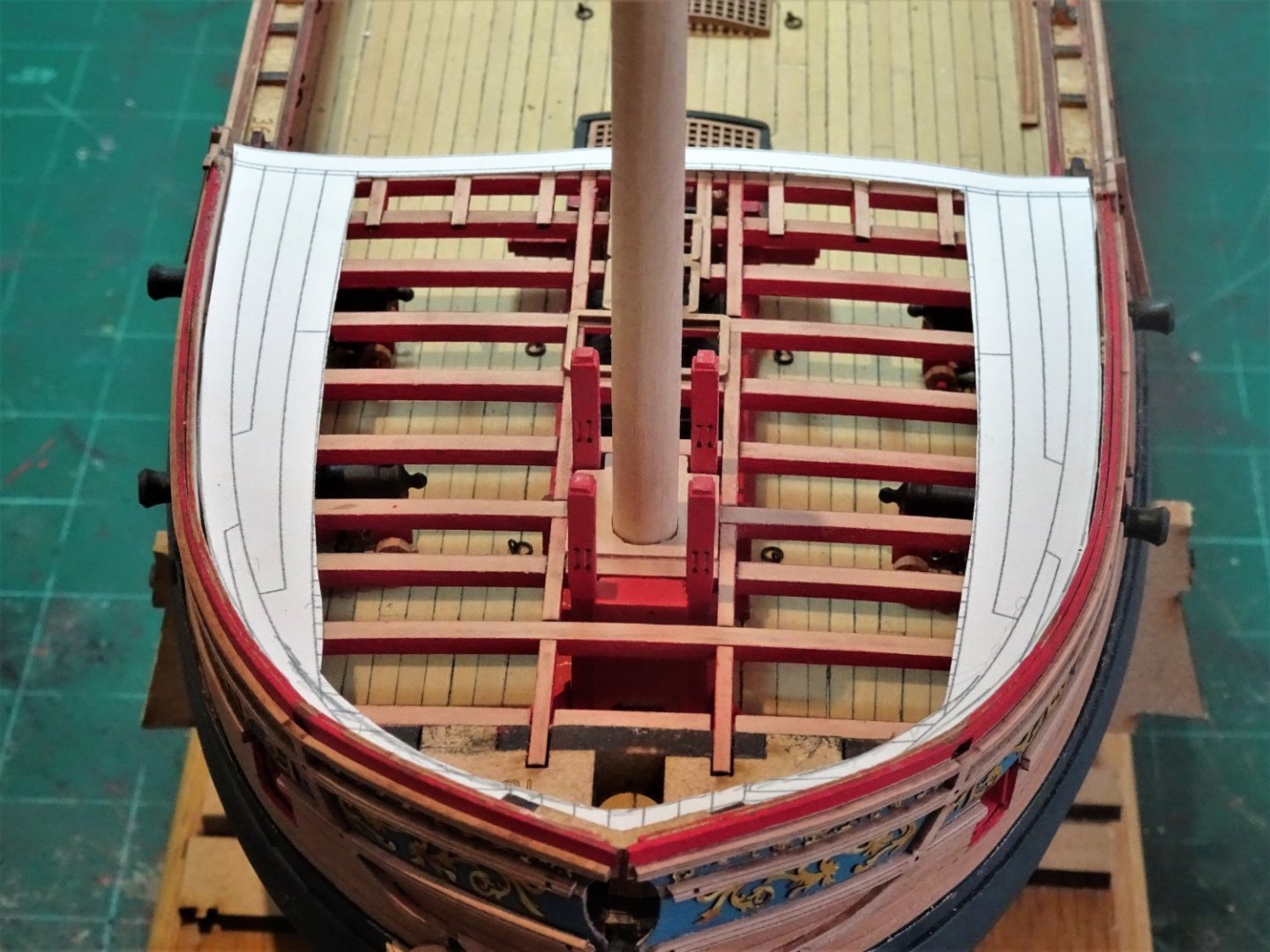
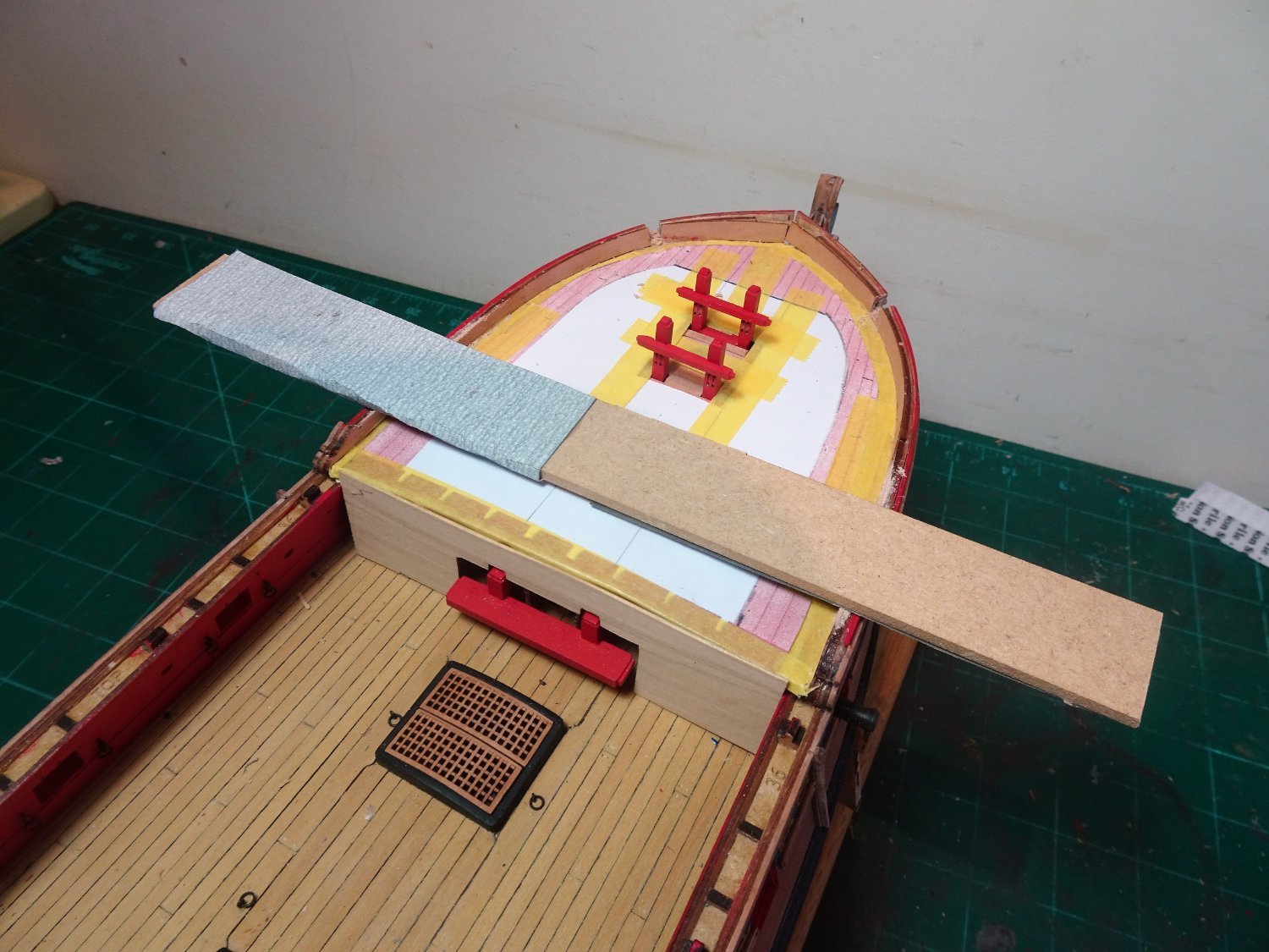
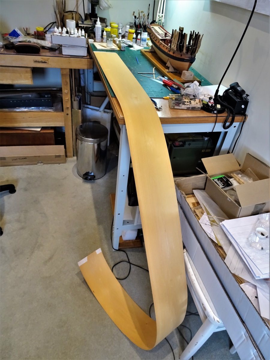
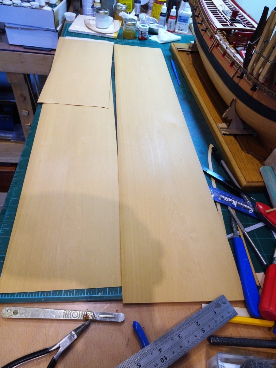
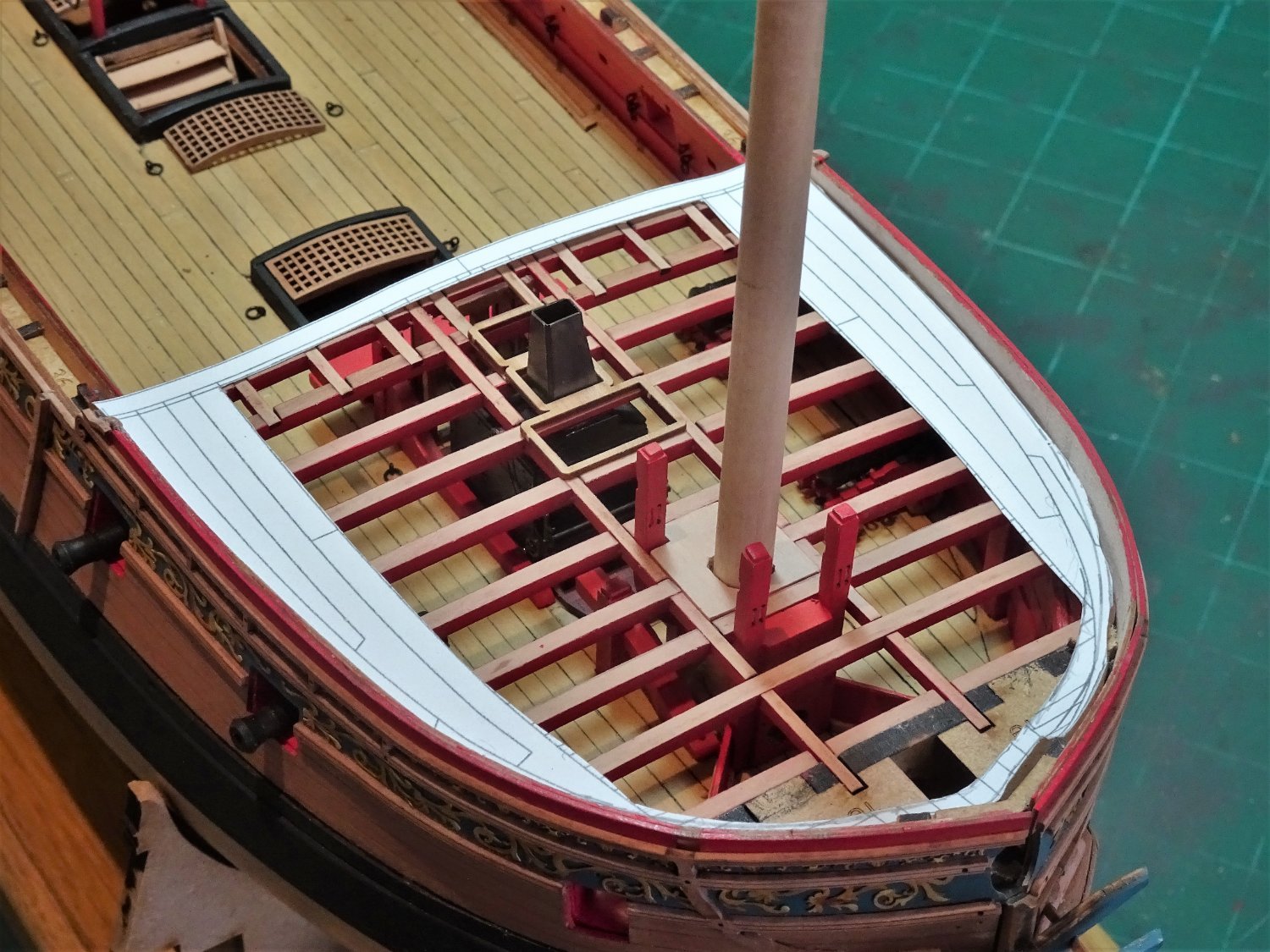
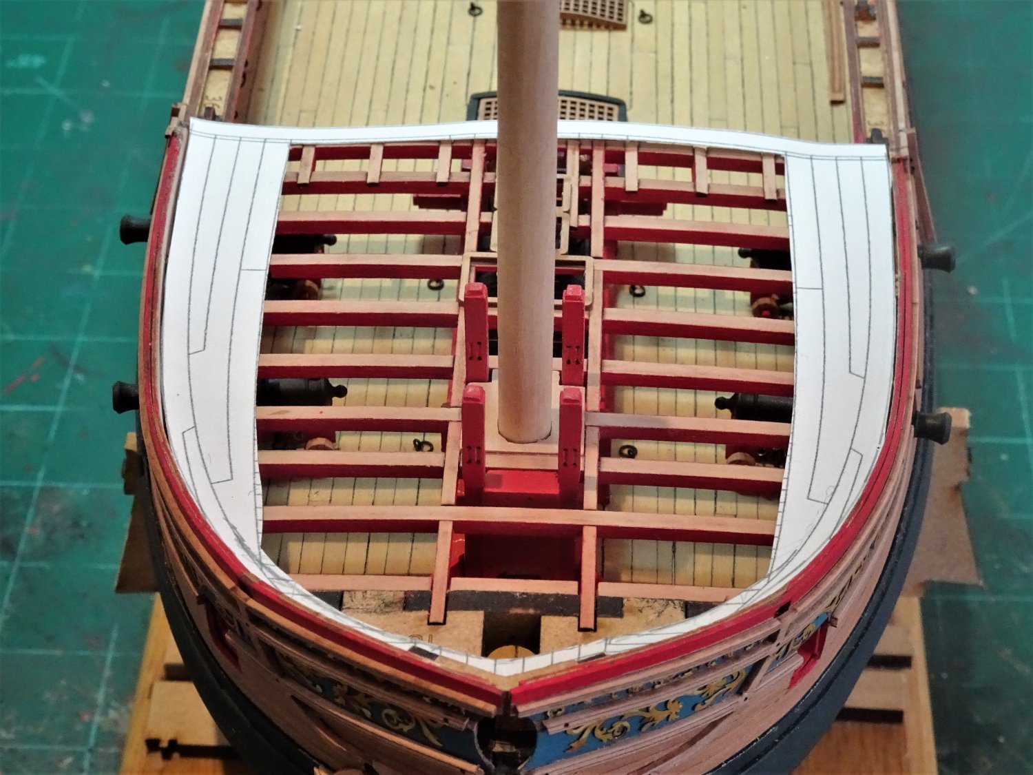
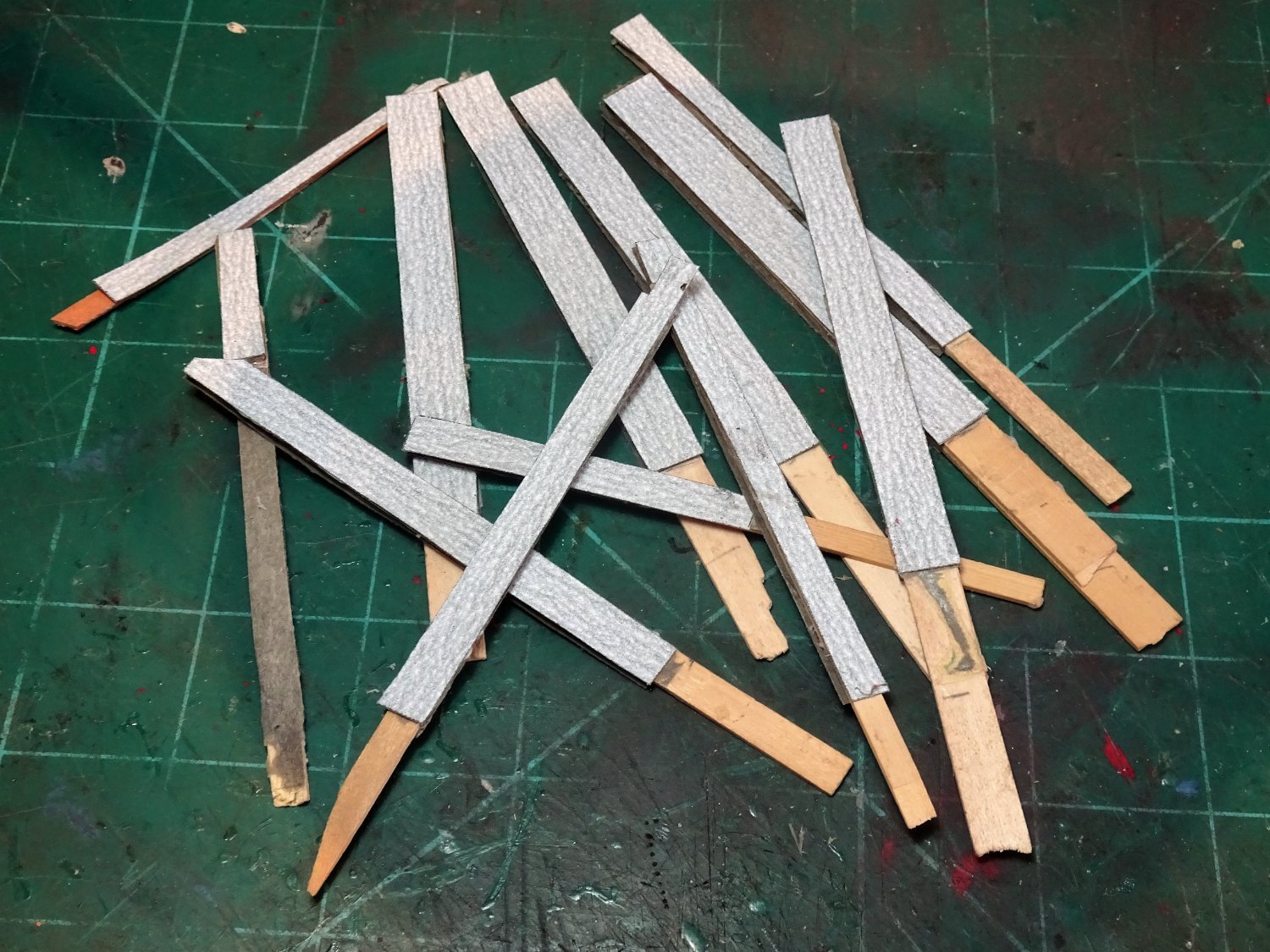
Post One Hundred and Six Foc’sle deck cont’d. 6396 6403 The sub- deck is glued into position. The first consideration is the Margin plank, Sphinx has a tight turn at the bow which makes fitting more difficult. There are two options, cut it out of suitable sheet stock or edge bend it using heat. Edge bending 6mm wide x 0.6mm strip is an almost impossible option, even with repeat soakings, bendings, and the application of a hot iron, the result is not pretty. Where is a piece of 0.6mm Boxwood sheet when you need one to cut the margins, not in my workshop. An order is submitted and the item delivered in 24hrs, great service from Original Marquetry. 6399 When I ordered this ‘sheet’ I hadn’t quite realised how long it was, I was primarily concerned with width and depth. 6400 Still, I now have more than enough to satisfy any future needs. 6405(2) A template for the margins is taken from the sub deck and glued to the Boxwood sheet. 6407 This is thin enough to cut with a scalpel; needs tidying up and adjusting for the inner bulwarks yet to be fitted. The plan is to fit the inner bulwark patterns directly on the engraved deck pattern, now my sub -deck, fit the margins to them. and add the thinner inner patterns atop the margins. B.E. 07/04/22


.thumb.JPG.2b6b387dee3cf96e54a370846c0b4698.JPG)
- 857 replies
-
- 21
-
-
- Sphinx
- Vanguard Models
- (and 1 more)
-
On my Pegasus build I secured the trunnions thro the brass barrels before blackening. I use a spot of ca. Once blackened any ca overspill is clearly shown. This was scraped off and the blackening process repeated until satisfactory. I also used a spot of ca to secure the monograms and vent, again clean up was required using a fine point scalpel blade before re- blackening. If you’re using brush applied varnish a light touch is required to avoid marking the blackening. I have never glued the barrels to the quoins, why would you. With Pegasus and the guns fully rigged I pinned the guns to the deck, the most secure approach. This is easier if the carriages can be temporarily positioned before the barrels are fitted, and the pin holes pre-drilled. This is the arrangement I used. With my current build the guns are simply secured using pva, but the built- in capping squares which means the barrels have to be fitted during the carriage assembly, makes the pinning approach more difficult. B.E.
-
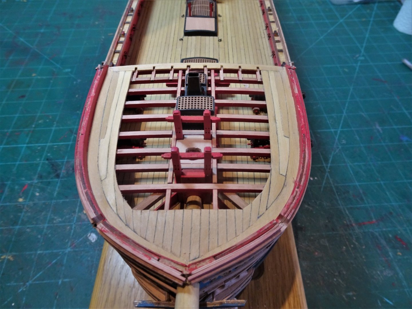
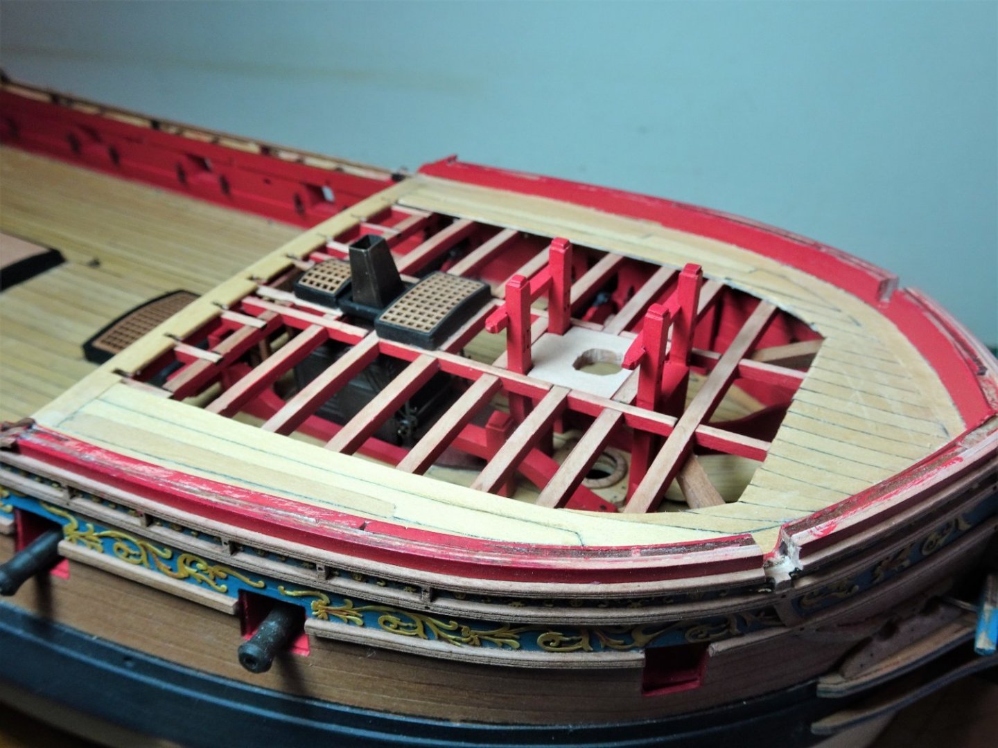
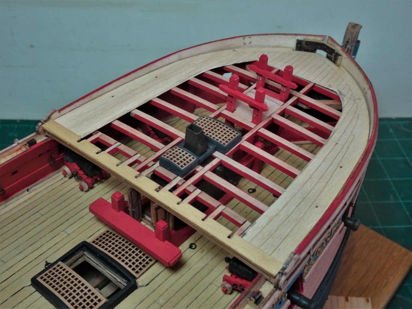
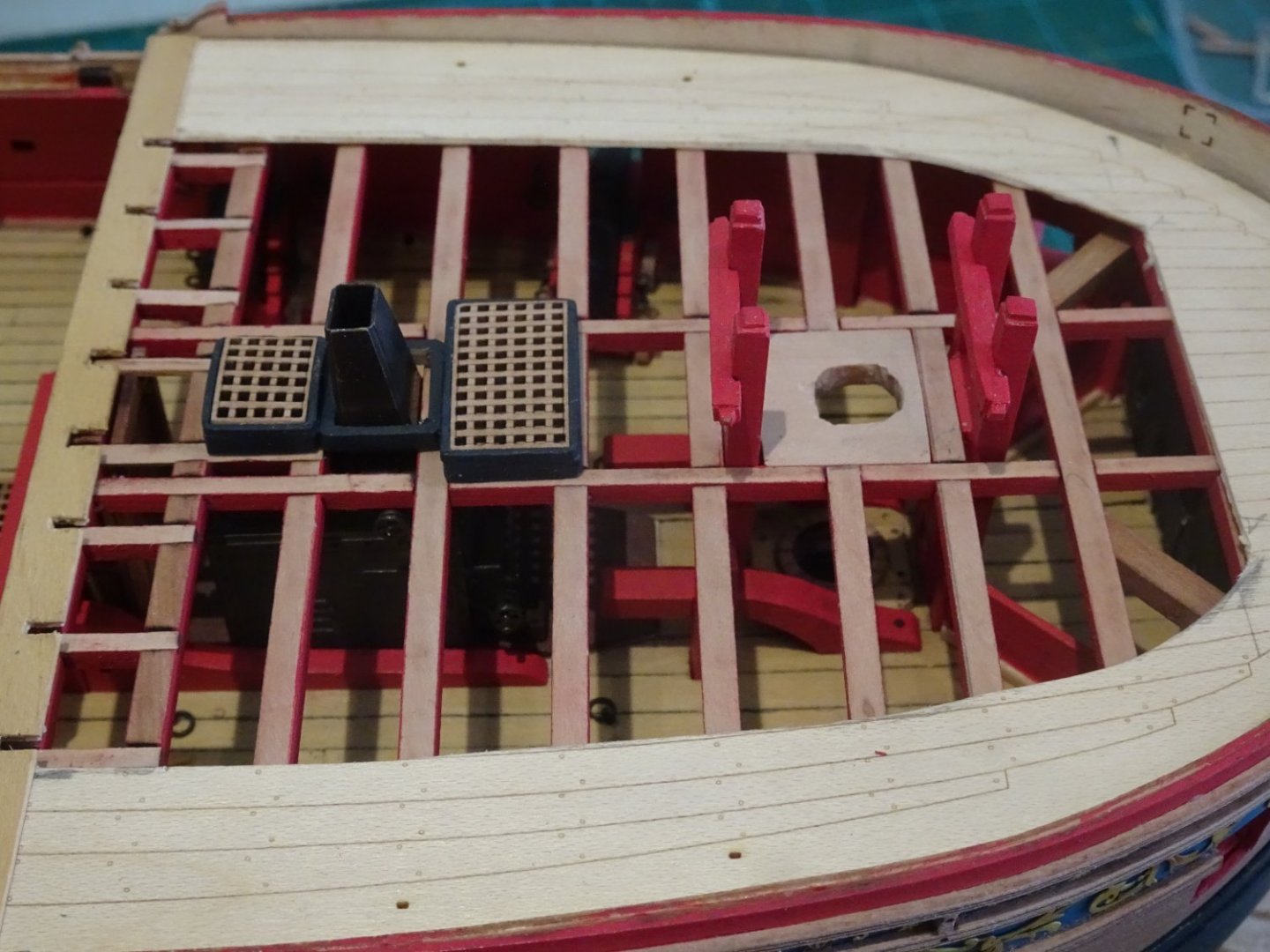
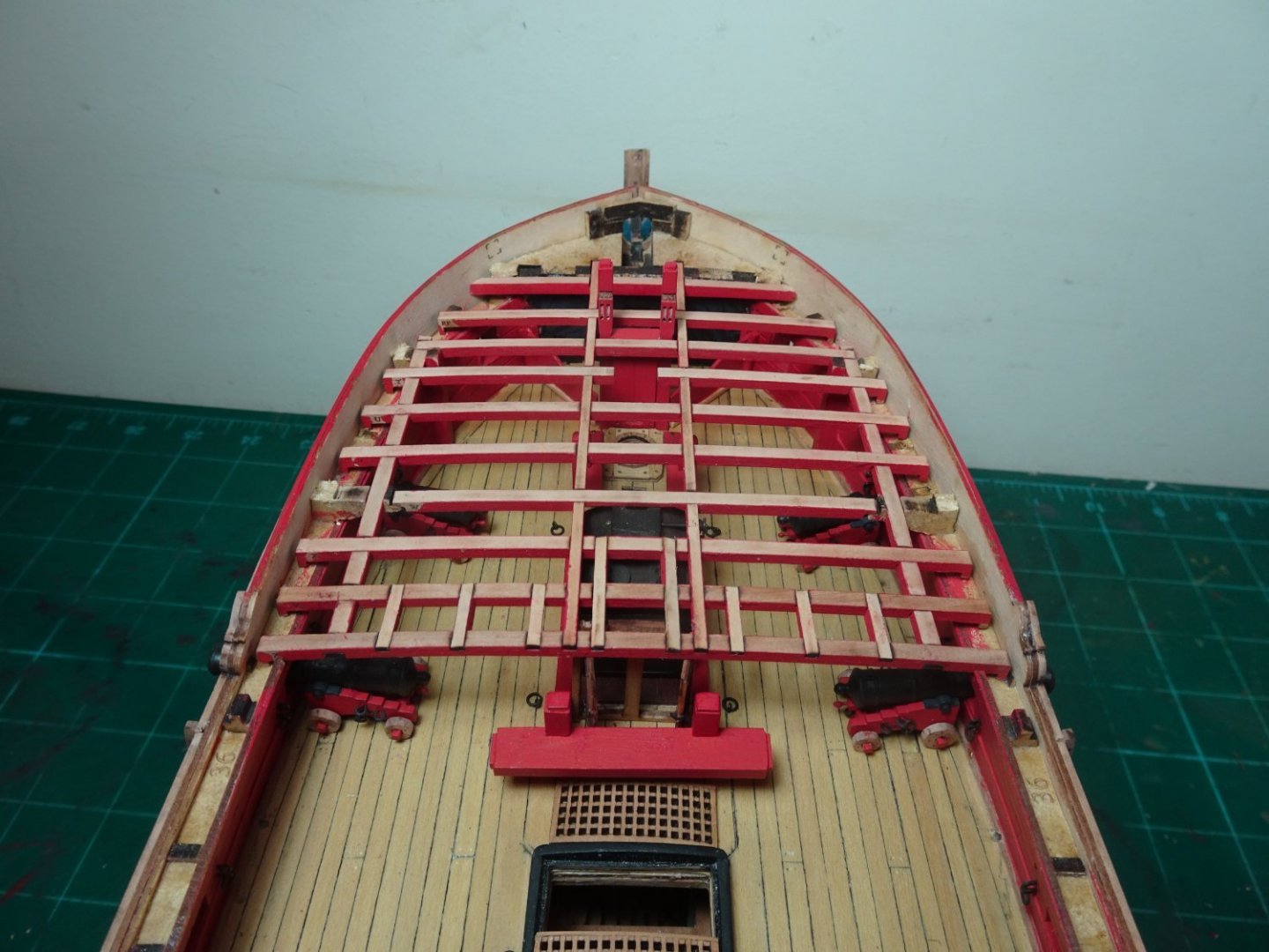
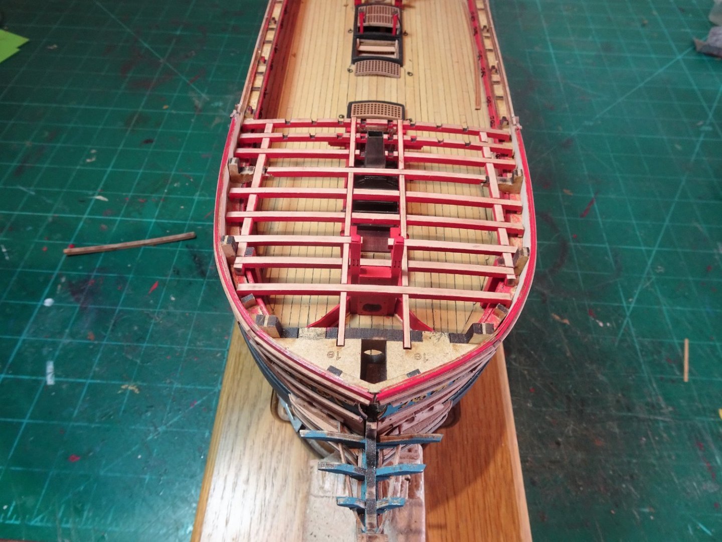
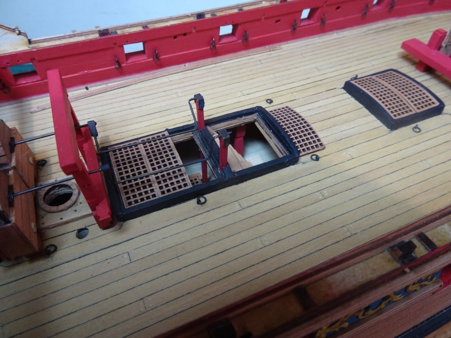
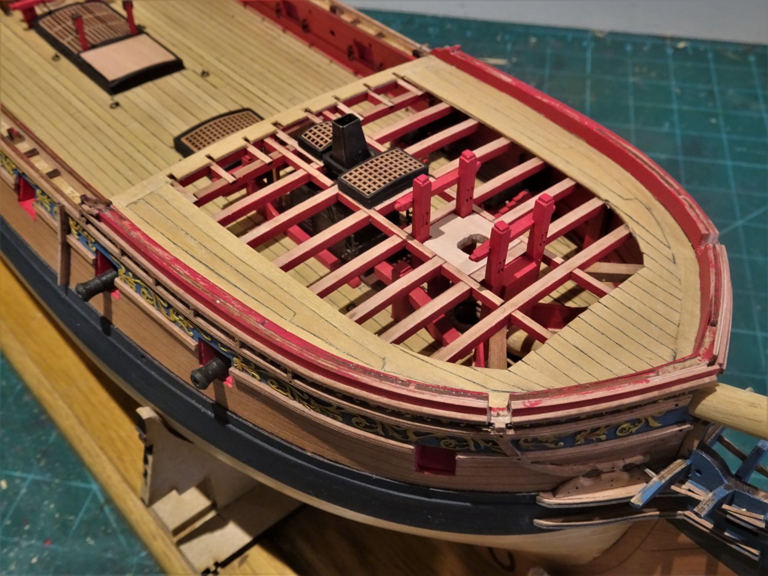
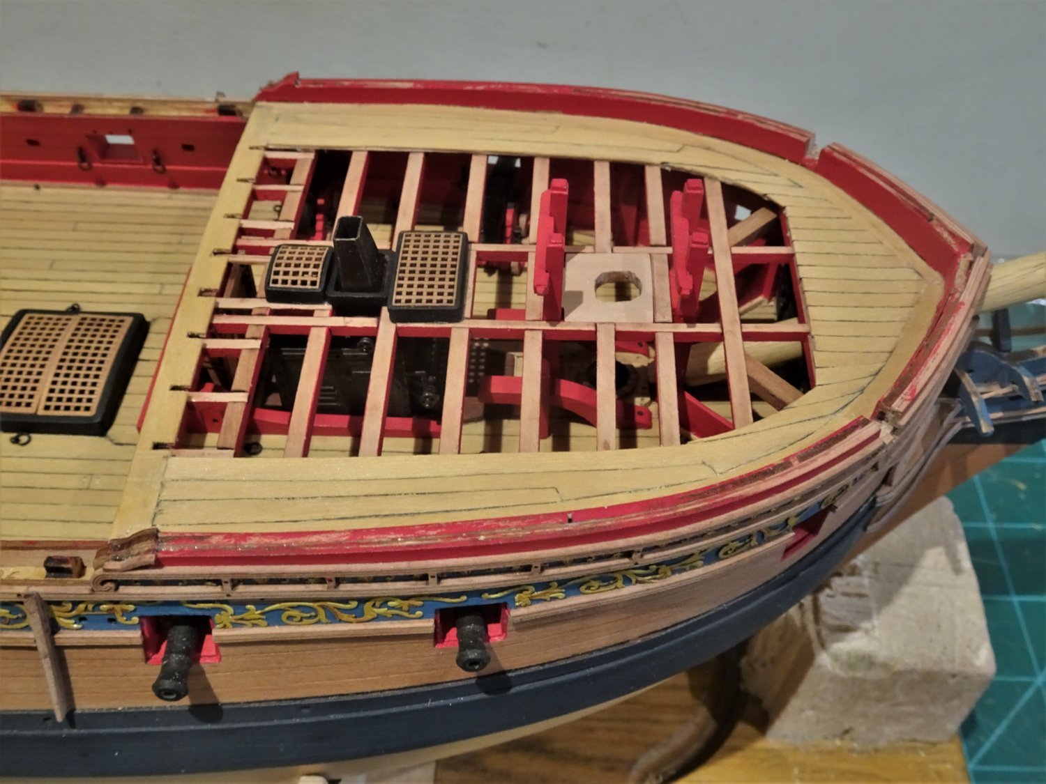
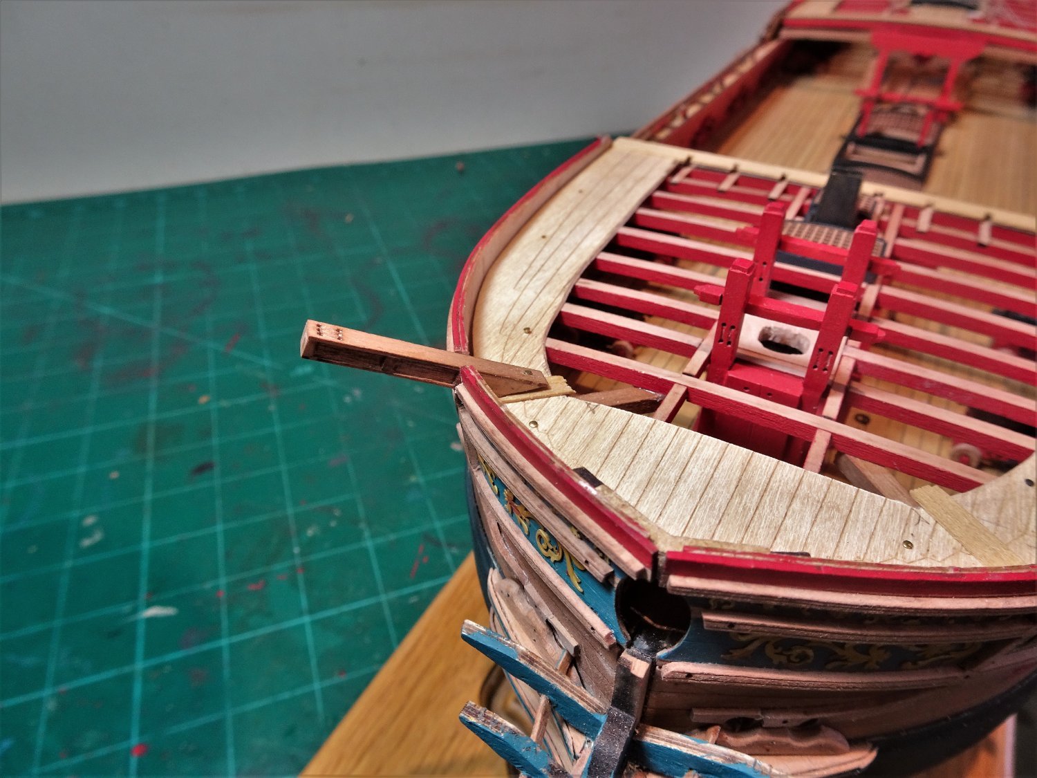
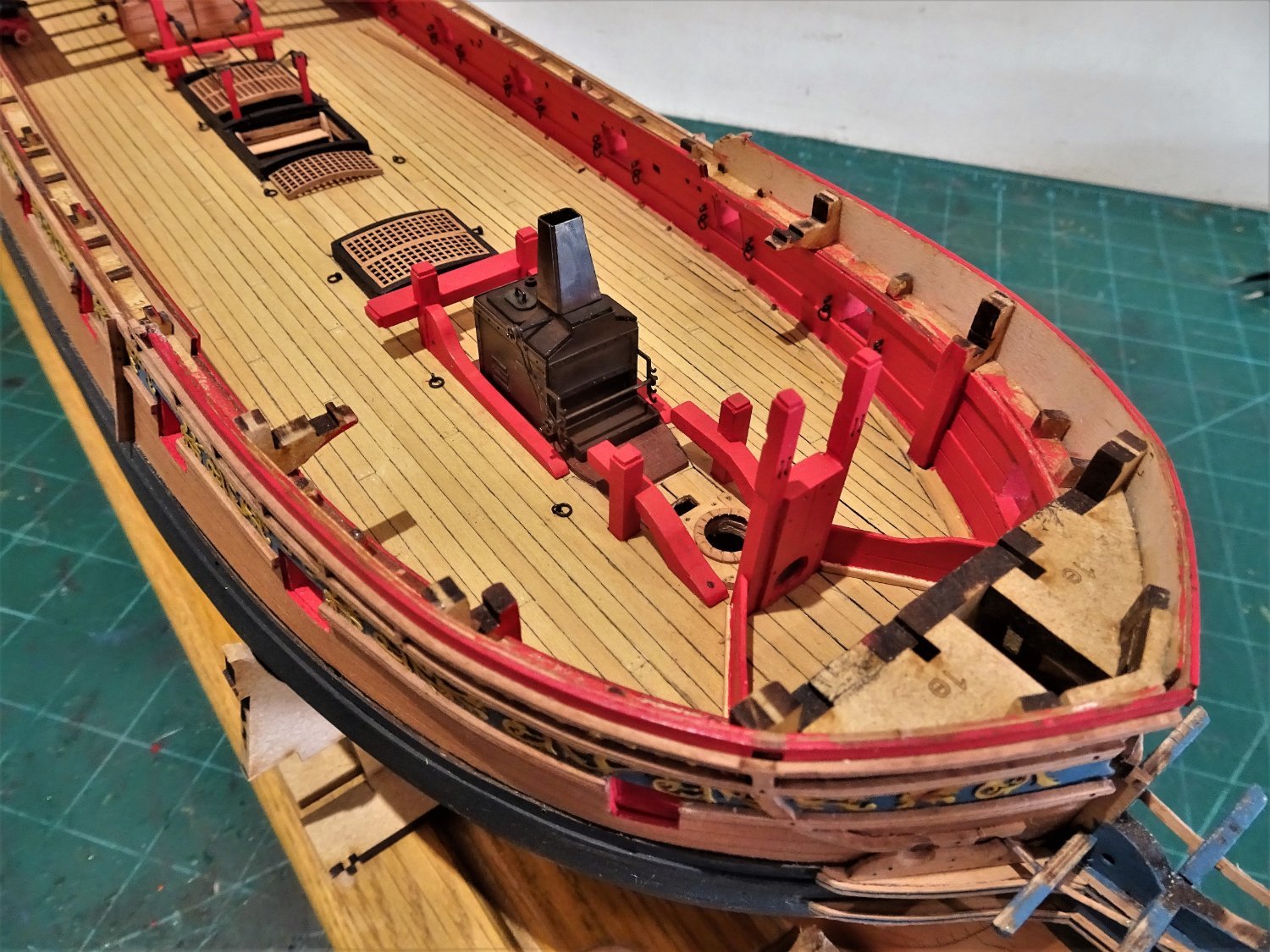
Post One Hundred and Five. Foc’sle deck cont’d A representation of the Cat Tail (beam) is attended to next. Part of this will be visible thro’ the unplanked deck so needs to be in place. Because of the design of the kit I can only display the aft end of the tail as it fixes beneath the deck beam forward of the Bowsprit stop. 6374 The forward end is abruptly terminated against the kit bulkhead beneath the extra beam I fitted at the very forward end. The Cathead position is marked on the bulwark and it is suggested that this be enlarged by filing out to suit once all the decking and inner bulwark patterns are fitted, and the Cathead inserted thro’ from the outside. This seems to be an awkward approach to the job, I cut a slot in the outer bulwark to facilitate a trial fit. 6392 I need to ensure that the Cathead aligns with the Cat Tail. 6388 The ‘false’ deck is temporarily pinned into place with a deck piece to facilitate alignment and fitting. 6387 Not fully adjusted at this stage but the stive looks pretty steep. A small adjustment to the cross beams of the Bitts; I filled in the belay pin holes. 6380 There is evidence that such items were not in use at least in the early years of ships of this era, and many contemporary models do not show them. 6373 The Foc’sle steam grating/ Flue assembly is modified to reflect its fixture to the deck beam/carlings, and is given a slight round-up to the head ledges/gratings. The provided veneer deck pattern deck piece is modified to suit my arrangement, and will be planked over using Boxwood strip. 6371 I have already fitted the breast beam decking strip with slots to take the rails and Belfry which will sit directly on the carlings. Before I glue this in place I will check out how the planking strips actually relate to the pattern. B.E. 04/04/22

.thumb.JPG.86e18f6b2e80c201b24665df4ad6b346.JPG)

- 857 replies
-
- 23
-
-
- Sphinx
- Vanguard Models
- (and 1 more)
-
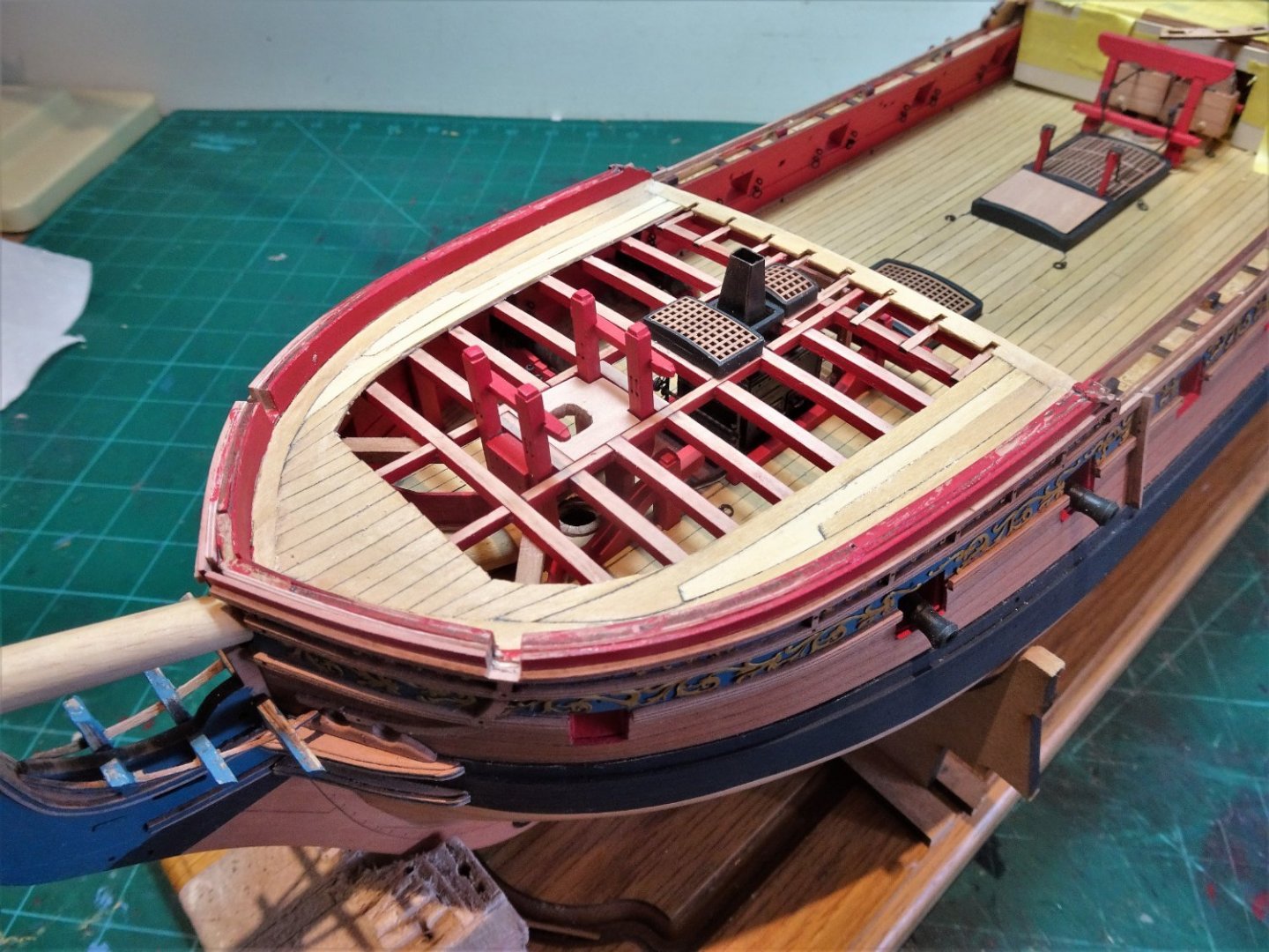
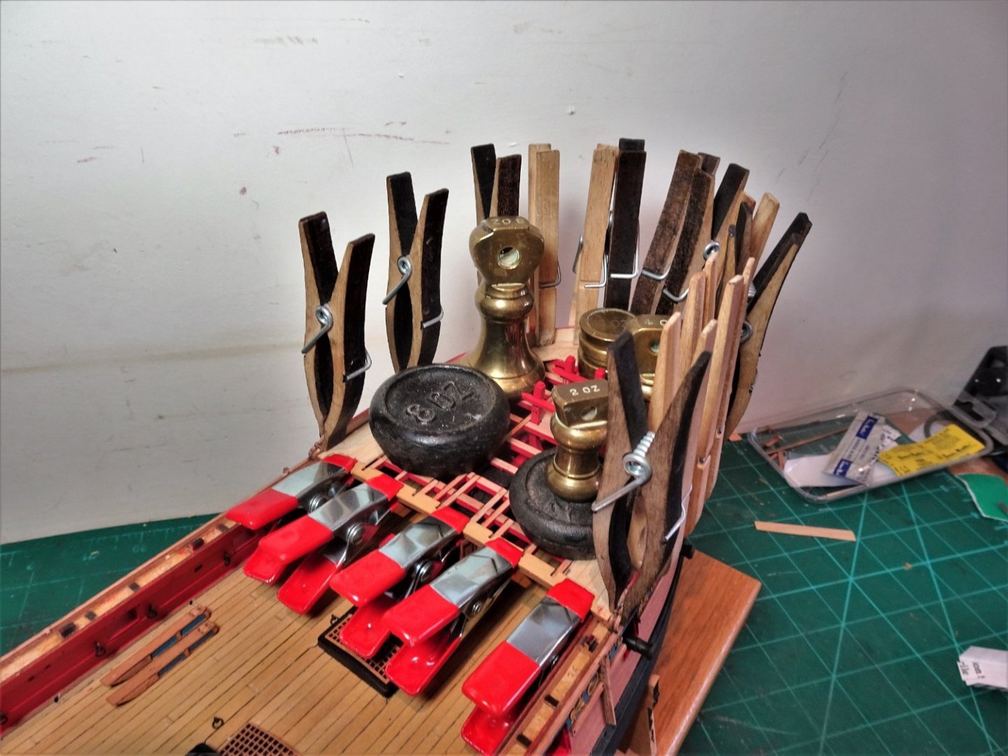
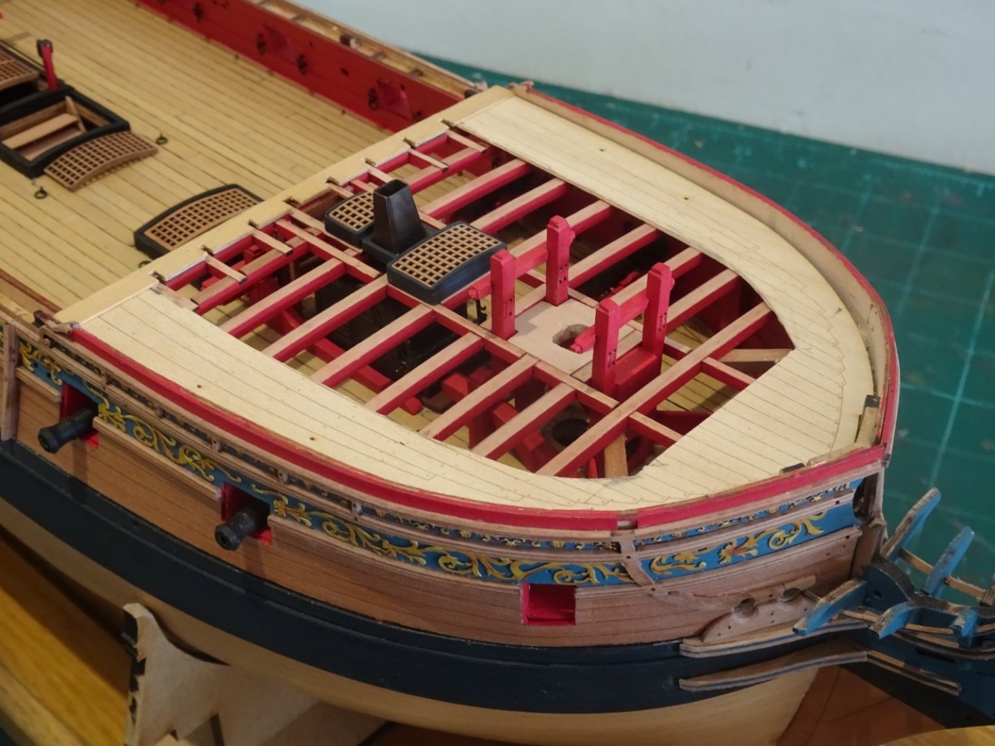
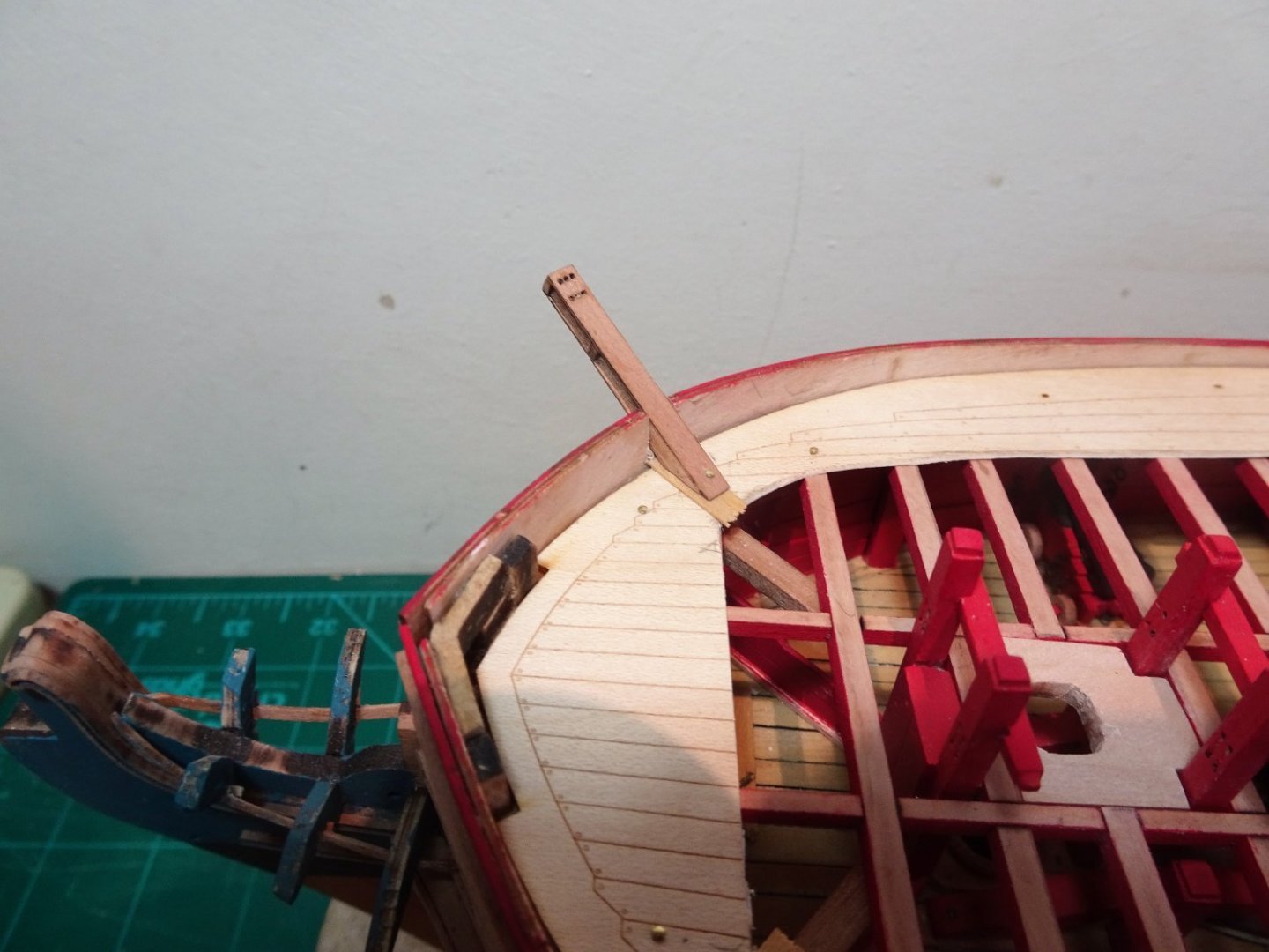
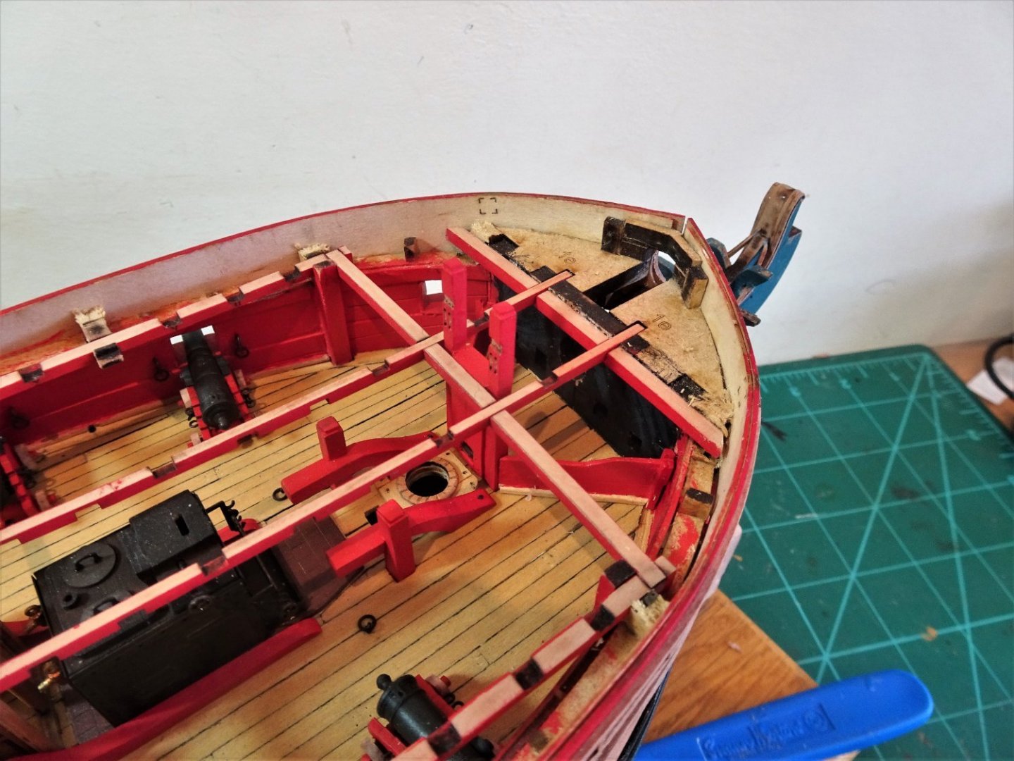
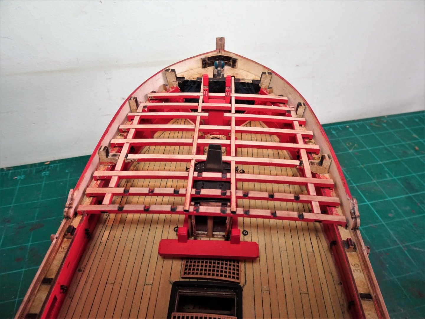
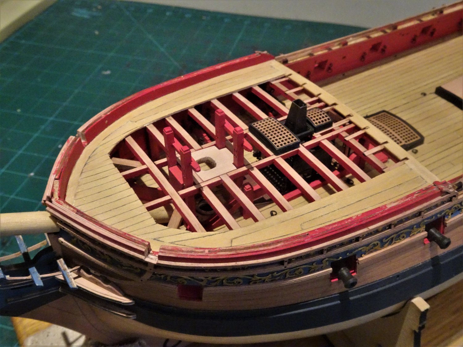
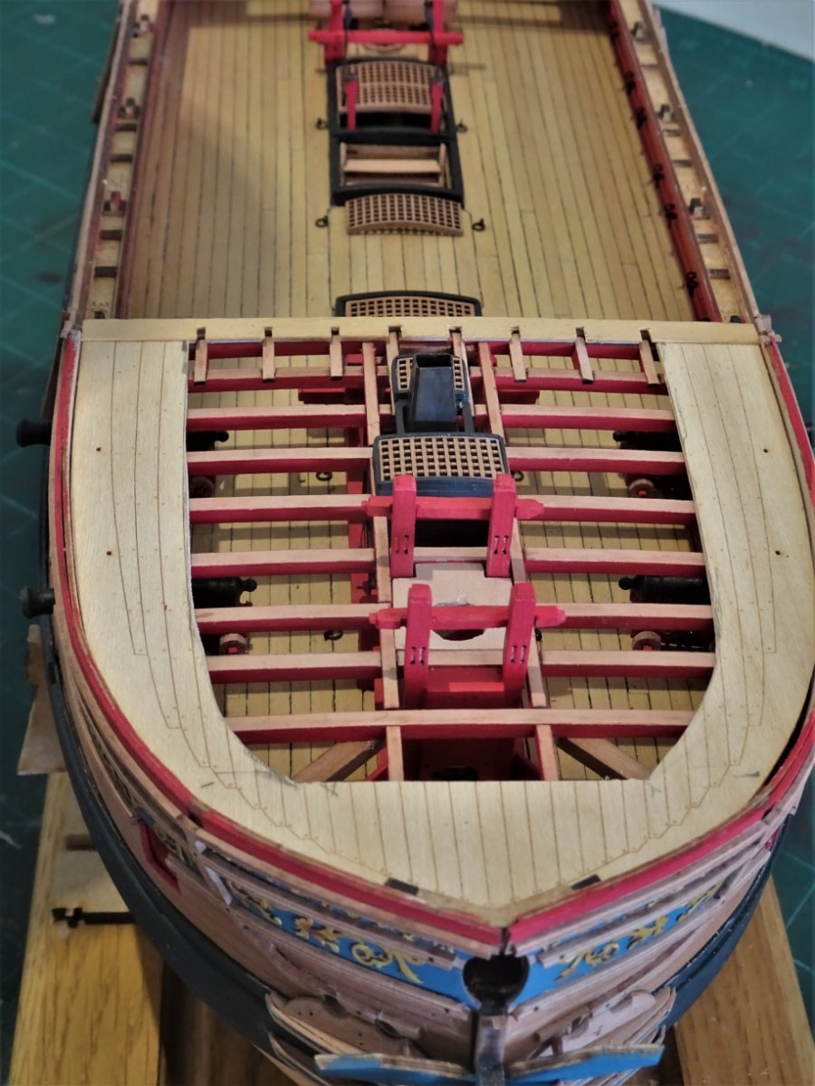
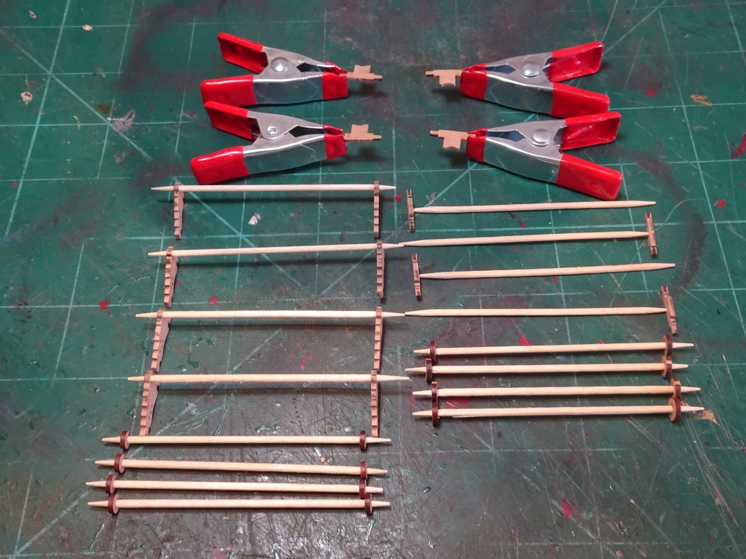
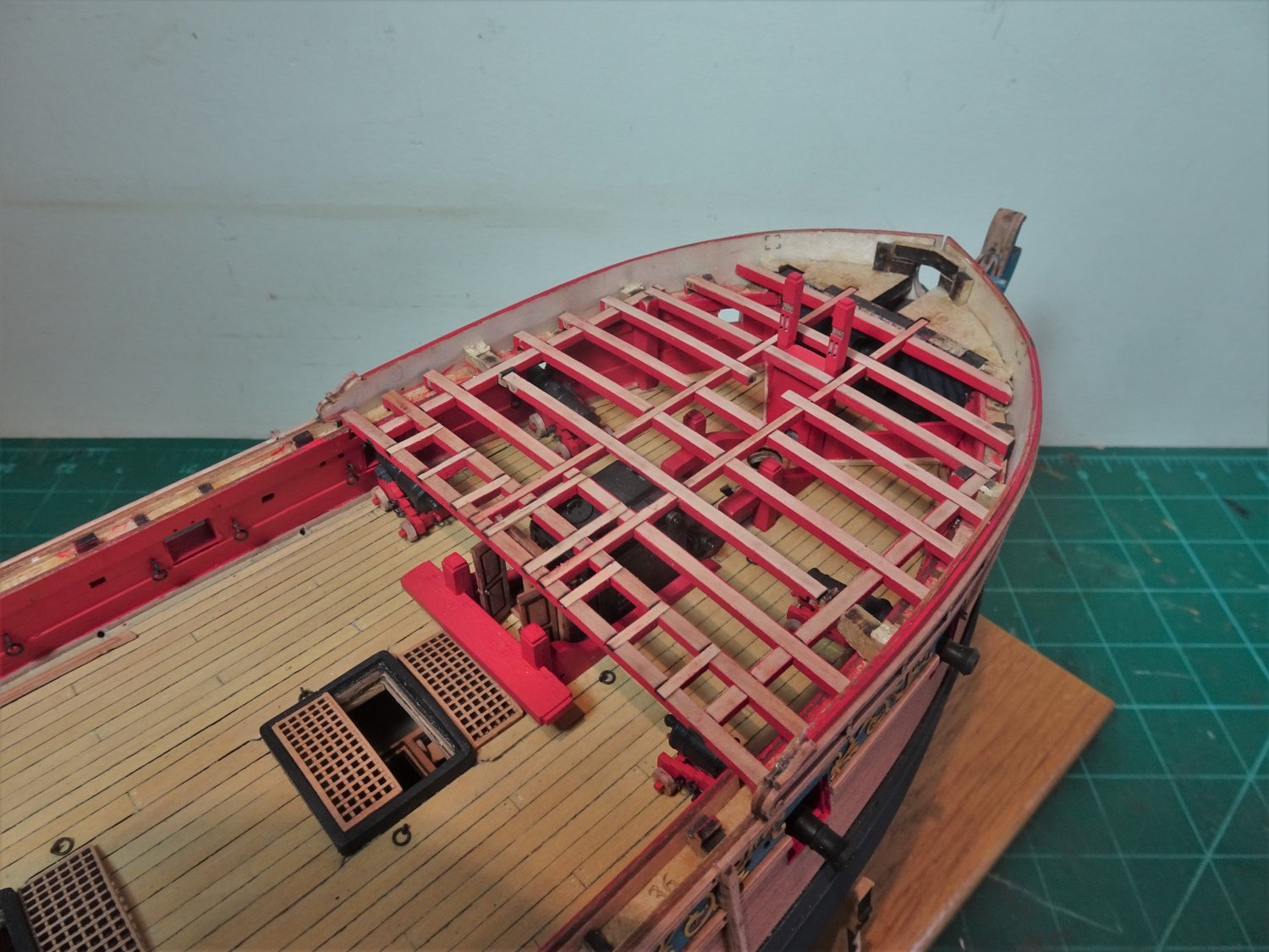
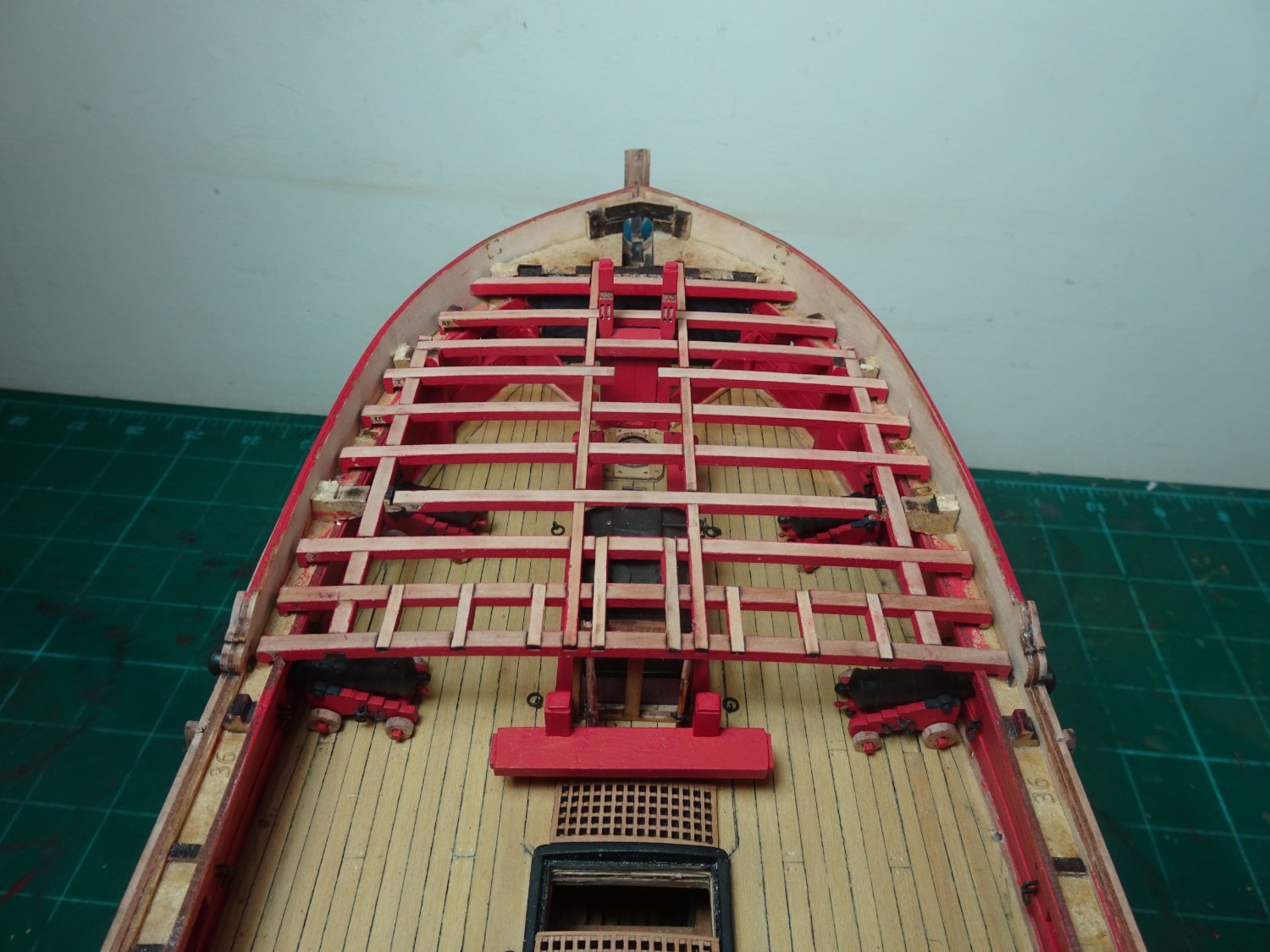
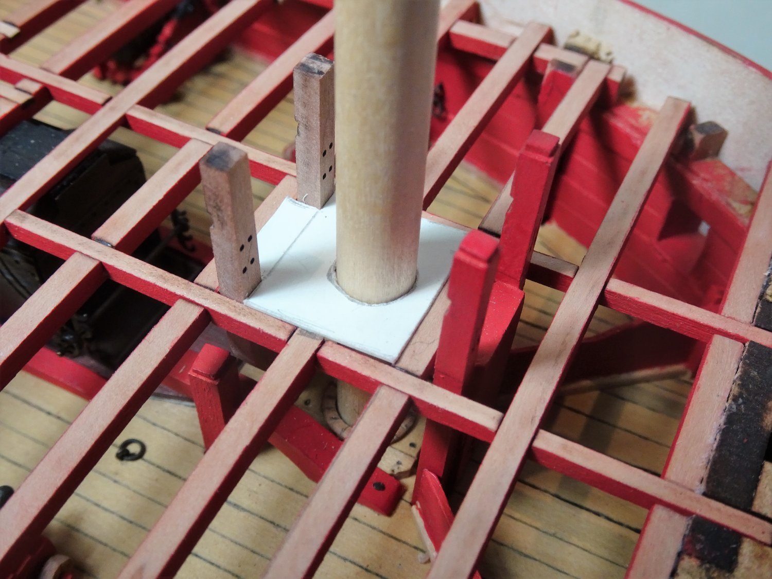
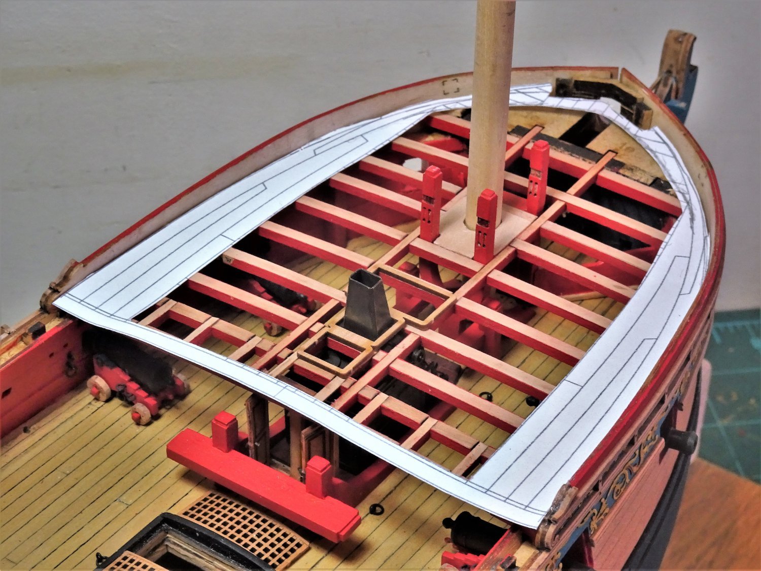
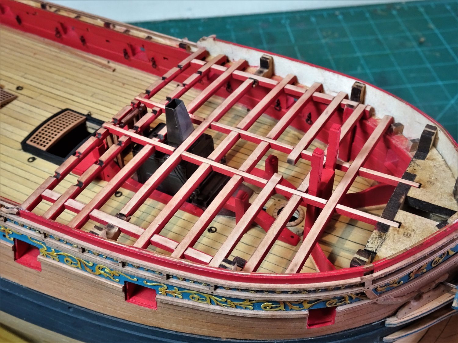
Post One Hundred and Four. Fore deck considerations. Before I can do anything further with the Foc’sle the four guns have to be put into place. 6292 A production line approach is taken for painting and assembly, a repetitive job, but I do like those resin guns. 6342(2) The last thing to fit are the Quoins, the handles are represented by a pva blob. 6349(2) Once cleaned, coated with spray matt varnish, and weathering powder applied, they do look the part and I doubt I would return to brass versions. 6350 I will have to go with the kit set-up in relation to beams, but I added an additional beam against the existing bulkhead at the bow. This will provide a ledge to fix the Cat beam against its underside, and further mask the solid bulkhead. With the guns glued into place the deck beams are added. 6353 6354 I’m not sure why the two half beams either side of the mast extend beyond the carlings, perhaps it is just to provide additional support for the deck around the Foremast. I adjusted beams 460T to be flush with the inner edges of the carlings and prepared mast partners to fit in the space. 6362 A card template is used to form the partners. Once again Chuck’s ‘Winnie’ build has given me a lead, this time for planking the Fore deck. 6365 Tweaked to suit Sphinx I think I can make it work. 6367 6368 Additional planking will be required at the bow, but otherwise I will leave the deck un-planked. The next tricky little job is to work out the Cat beam position but for that I need to assemble the Catheads. B.E. 02/04/22

.thumb.JPG.262bf12f7f6ae4ff29df6dfffb9dc443.JPG)
.thumb.JPG.b370416df70e3d762ed4e8dd3ee21b8c.JPG)


- 857 replies
-
- 27
-
-
- Sphinx
- Vanguard Models
- (and 1 more)
-
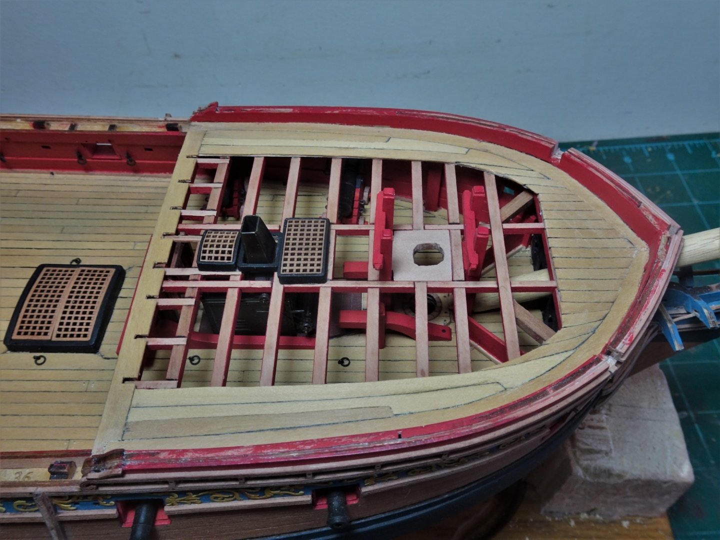
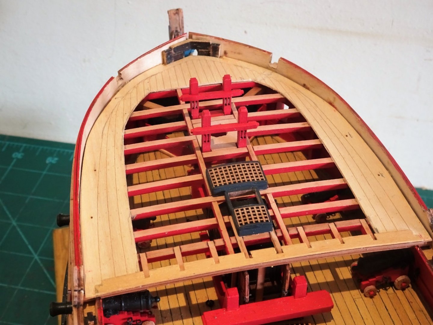
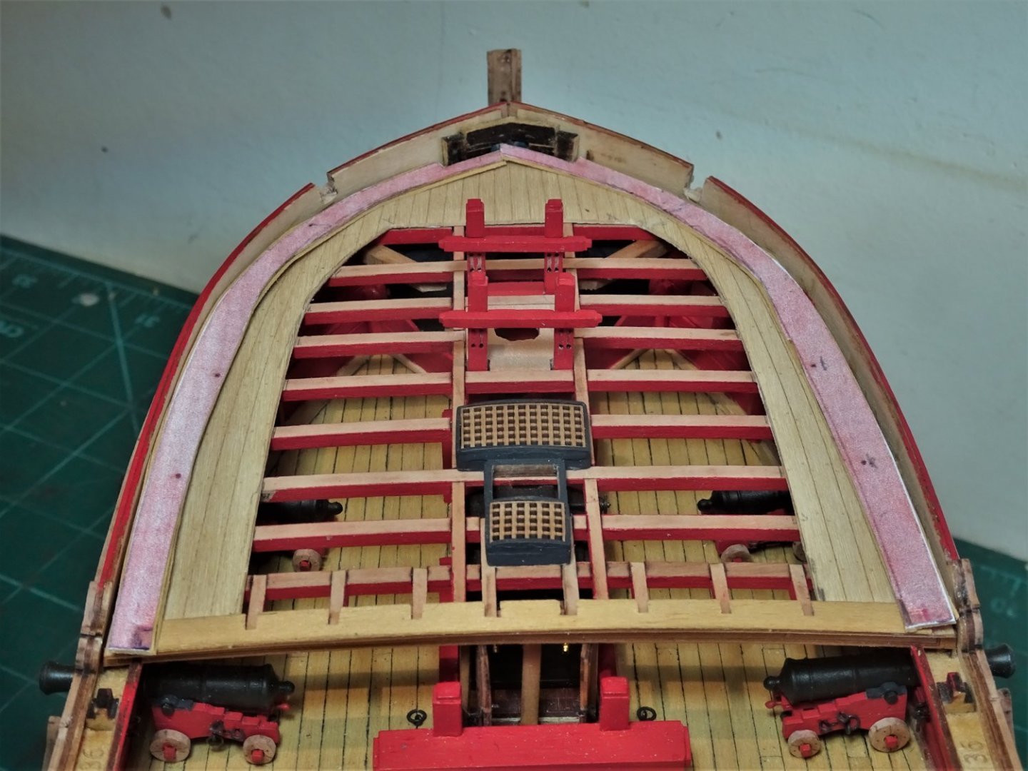
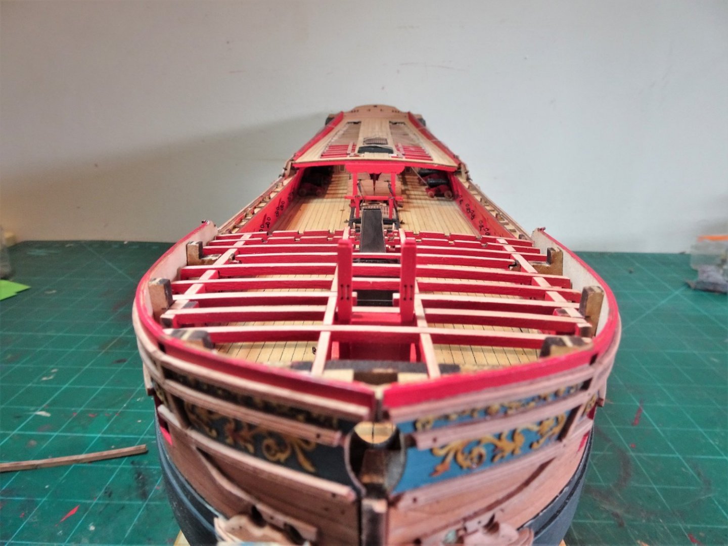
Post One Hundred and three. Fettlin’ the Foc’sle Beams. 6271 With a fresh set of sanding sticks prepared I am ready to get stuck into the char removal from the deck beams. Fortunately the last major exercise of this type. 6273 The beams are quite delicate and it’s worth repeating that it’s best to support them in a vice for sanding to eliminate the risk of snapping at the mortises. In trying to more authentically represent the deck beams of the Foc’sle I am faced with a trickier situation than with the Quarterdeck. 6274 The two carling parts (459) are not an authentic fitting. Together with the foremost and aftermost deck beams ’S’ and ‘Z’ they form a box structure to support the deck beams, with the consequence that the fitting of deck ledges is inhibited. This is not a criticism of the kit which was not designed for this level of detailing, but it means that the deck planking will need to extend beyond this point. I have decided to fit the Galley doors; the decision had to be made before the aft deck beam was fitted. Having painted the remaining beams they are trialled for fit to make sure that no nasty surprises are lurking. 6280 6284 6285 6286 It all slots together very cleanly. I have a lot of things to think about in relation to the Foc’sle. Fitting of hanging knees in conjunction with the beams, there are sufficient kit provided parts to do this. I like the look of the exposed beams and fancy leaving it more open than the Qtr deck. It will need planking along the bulwarks inboard to the outer carlings and on the solid bulkhead section at the bow. Other than that I am inclined to leave it completely un-planked but I will fit the coamings and gratings above the galley stove. There is the tricky question of the Cat beam running beneath the deck beams and the connection to the Cathead, it is not clear in my mind how to approach this yet. Still for the next week I will be enjoying the magnificent scenery of the Menai Straits. 5032 There has barely been a day over the past few months that I haven’t worked on Sphinx and I’m not sure I won’t get withdrawal symptoms, but Anglesey has its compensations, not least the wonderful photo opportunities. Cheers, B.E. 25/03/22


- 857 replies
-
- 26
-
-
- Sphinx
- Vanguard Models
- (and 1 more)
-
Well done Tim, she's a fine looking 'Swan', you've every right to feel proud of your achievement. B.E.
- 164 replies
-
- 3
-
-
- fly
- Victory Models
- (and 4 more)
-
Thanks for looking in Gary, there is a lot of evidence for the ‘solid’ galley doors either in isolation or as part of a Foc’sle Bulkhead. The Adm plan for Sphinx does appear to show this feature. It is an interesting idea that canvas screen may have been used instead, but many contemporary models show solid doors. These were not fixed but held in place by cants across the deck in much the same way as the bulkheads across the Great cabin. I can imagine the use of canvas screens within in the foc’sle, it was a popular spot for a temporary sick room, and the Hanging cabins are recognised as a feature on the lower decks, altho’ I never been motivated to model them. Regards, B.E.
- 857 replies
-
- 2
-
-
- Sphinx
- Vanguard Models
- (and 1 more)
-
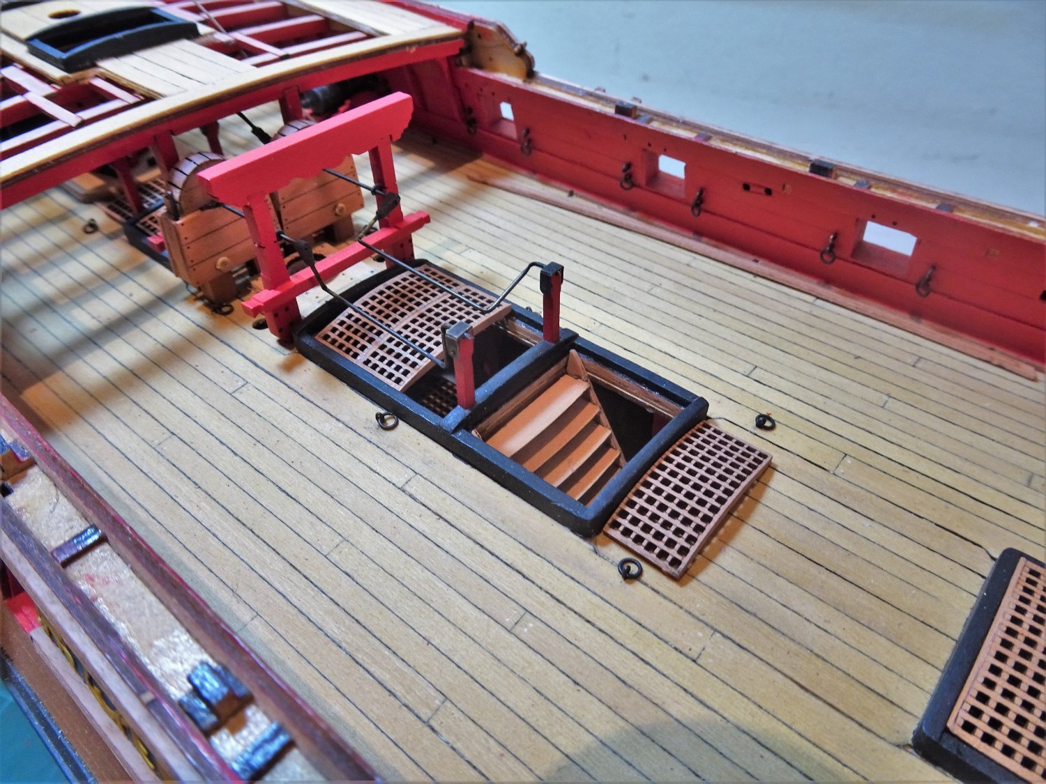
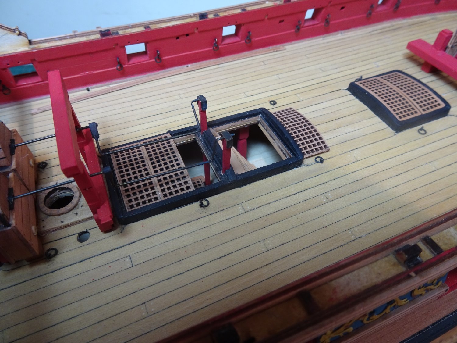
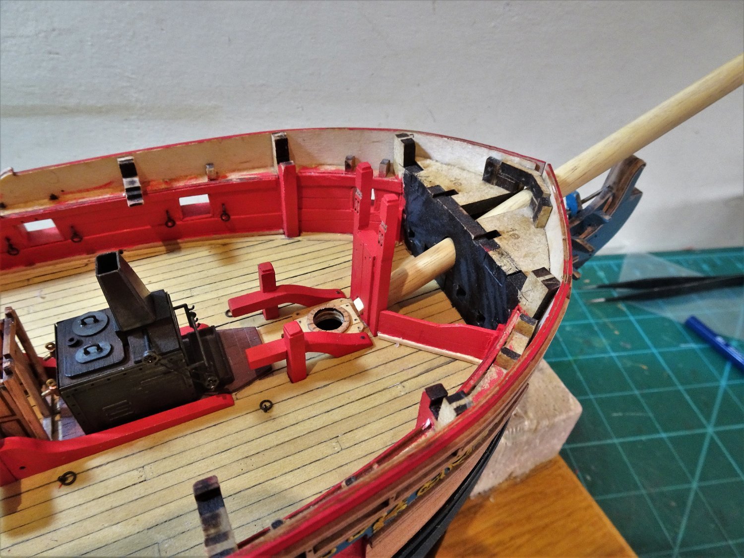
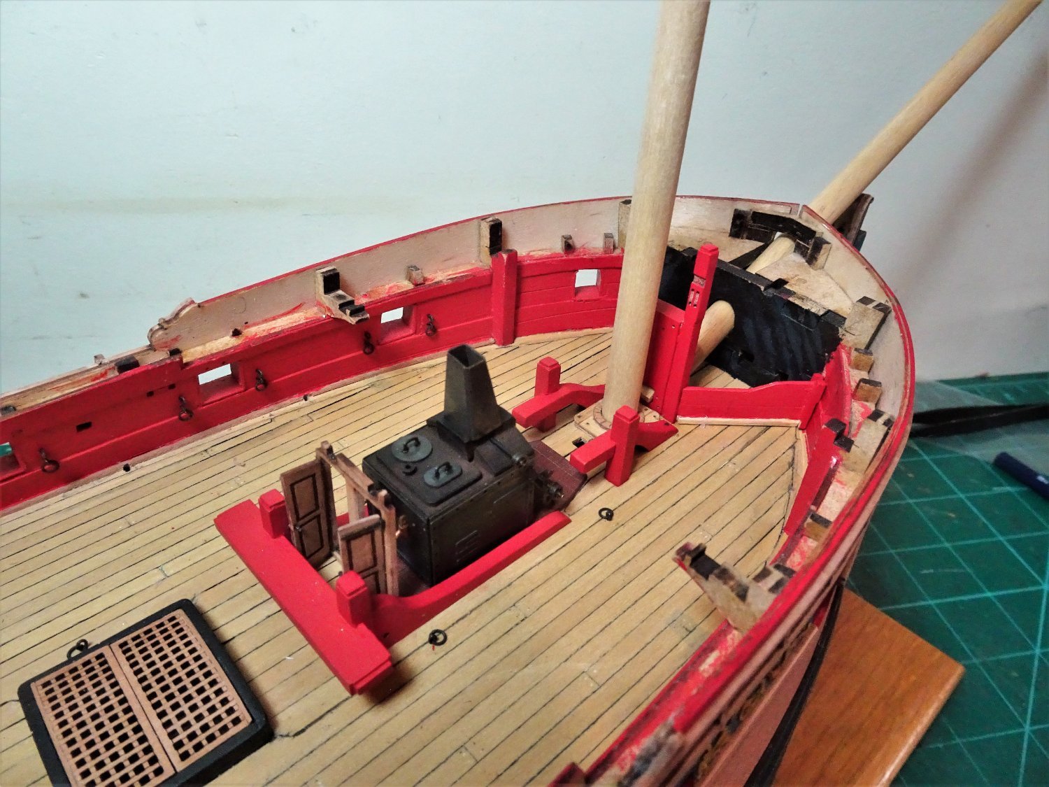
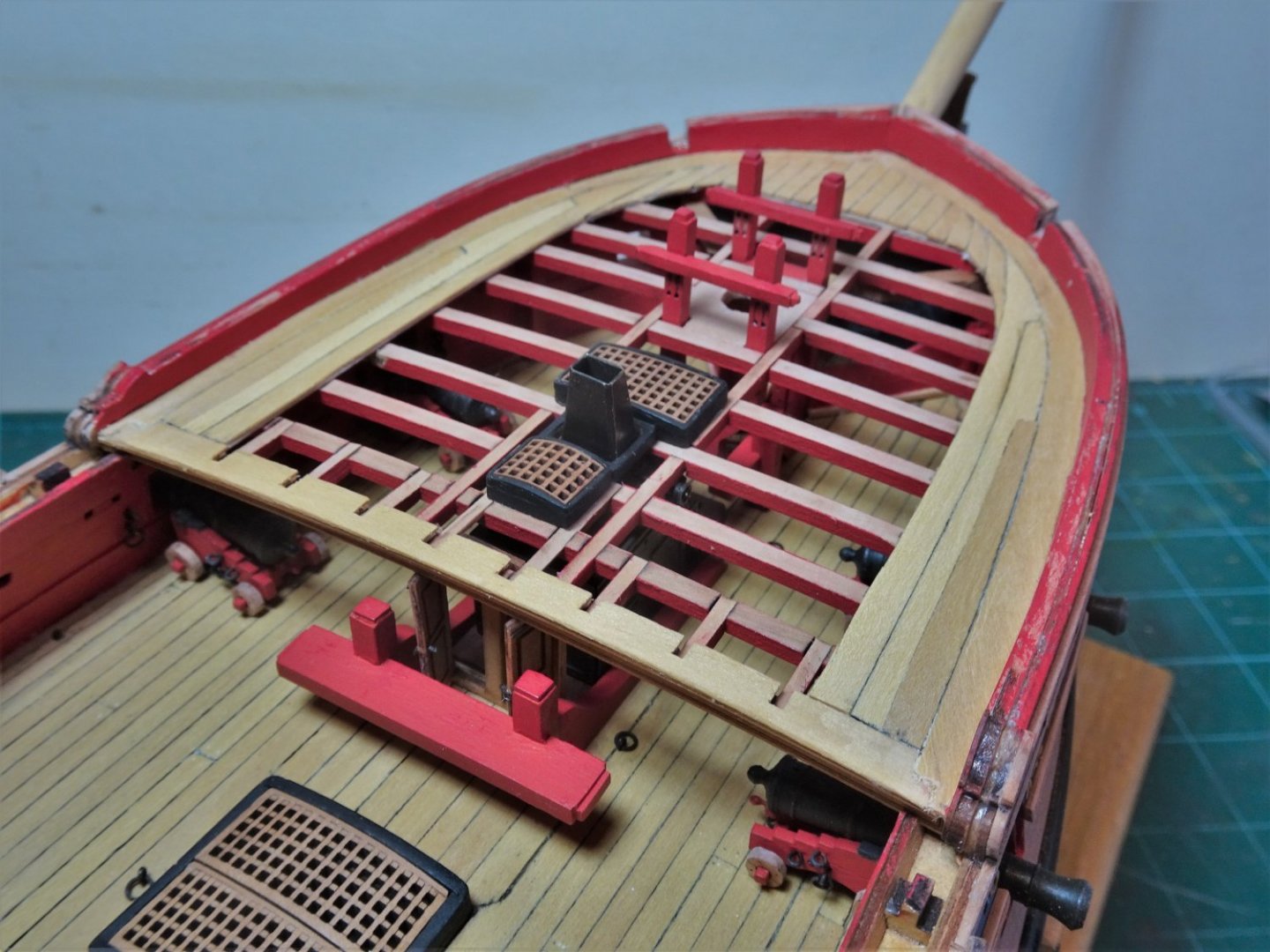
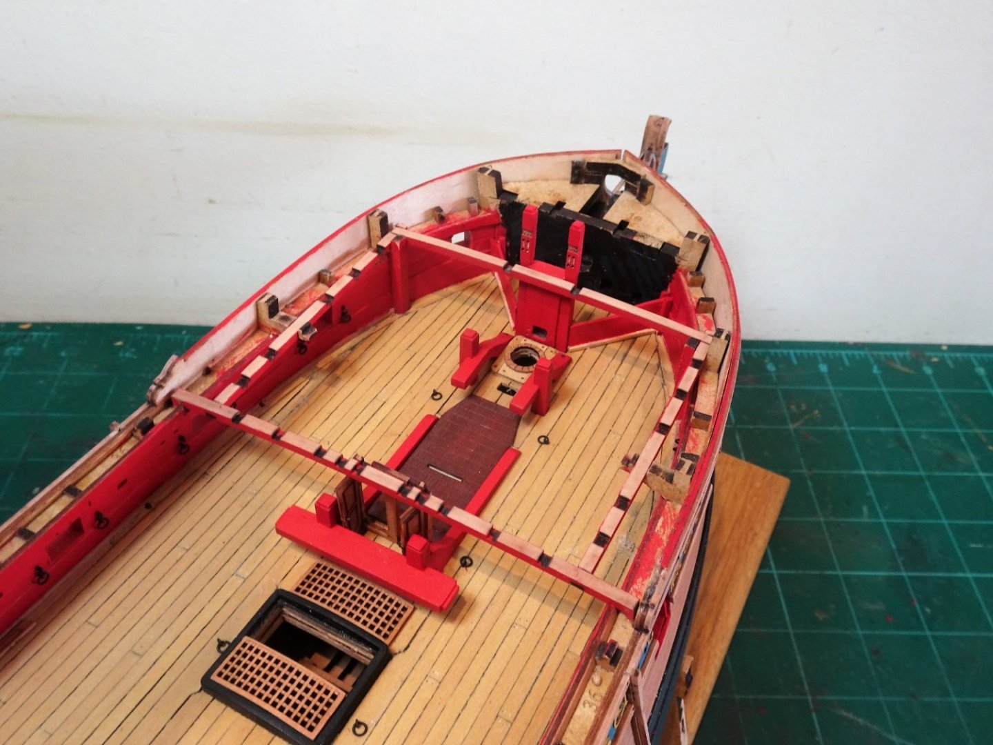
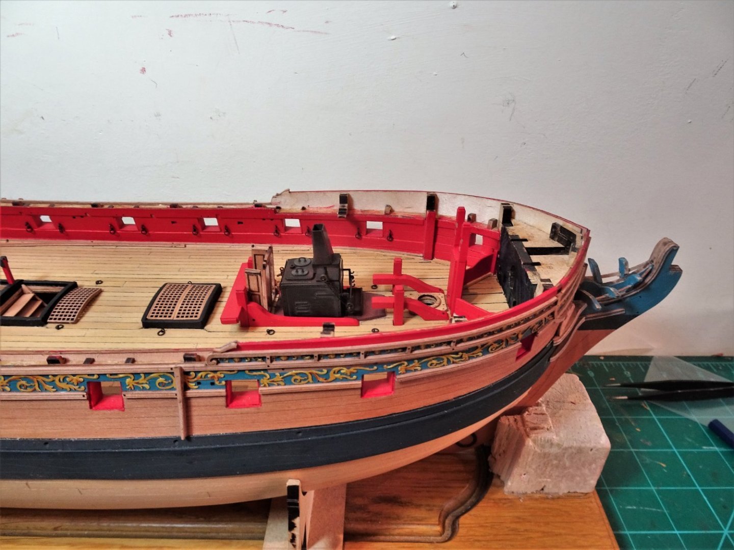
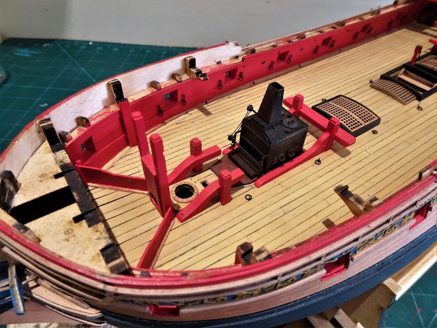
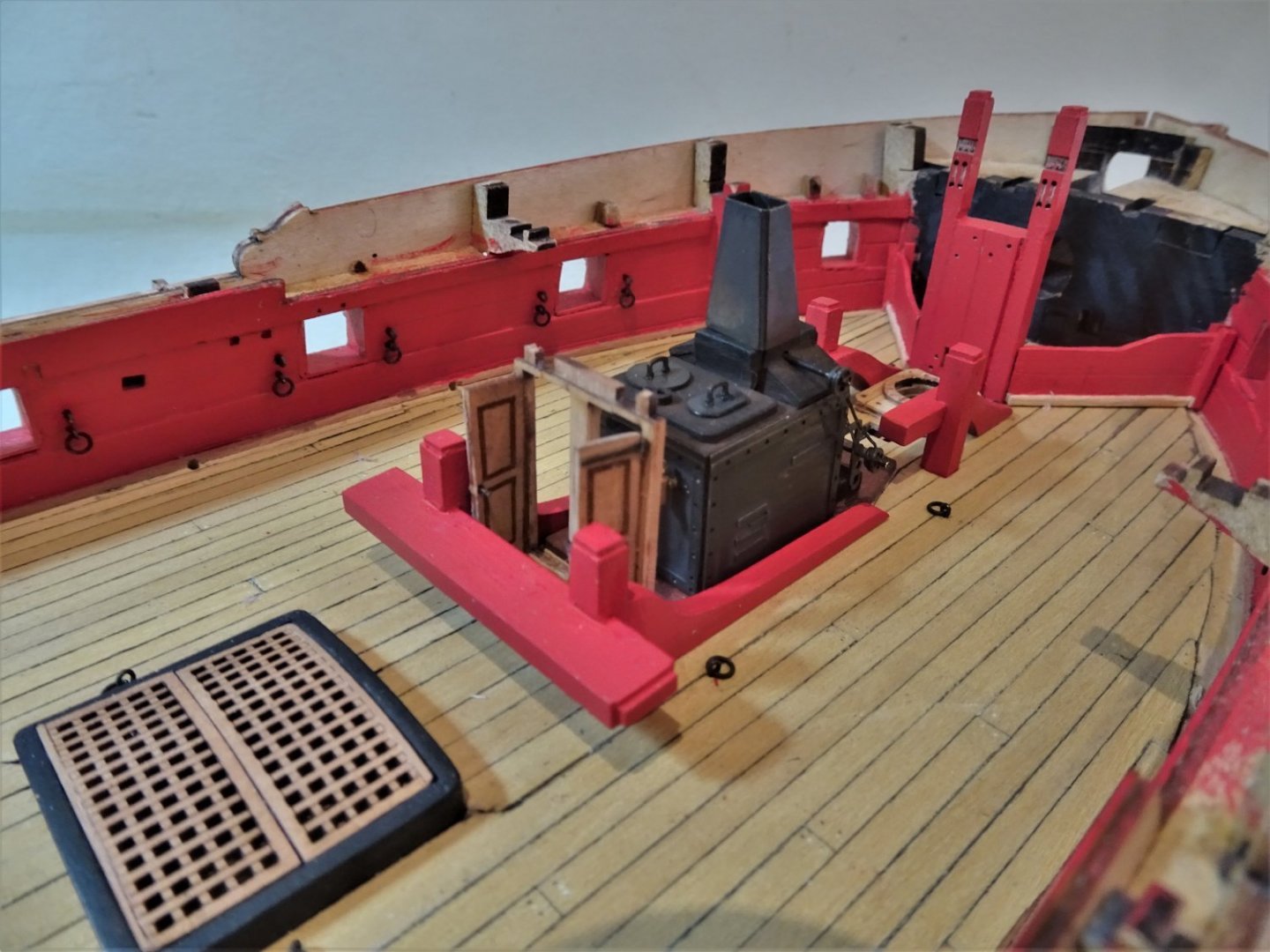
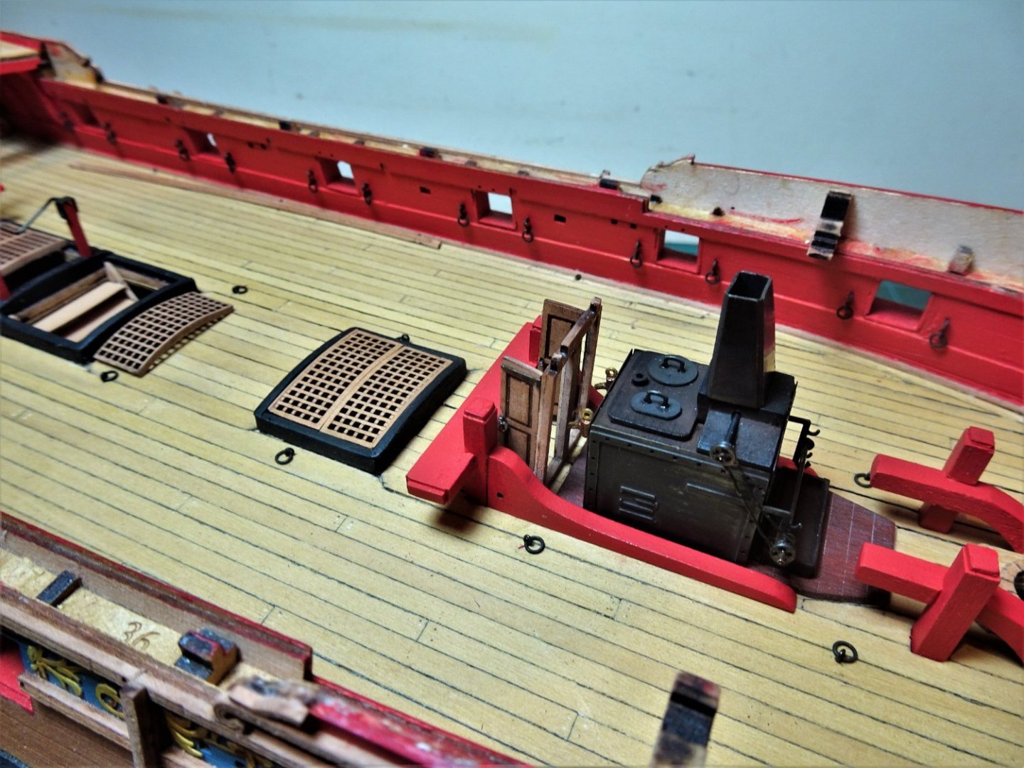
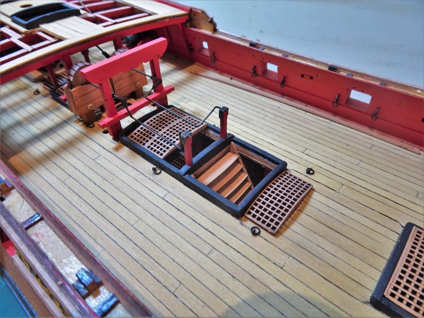
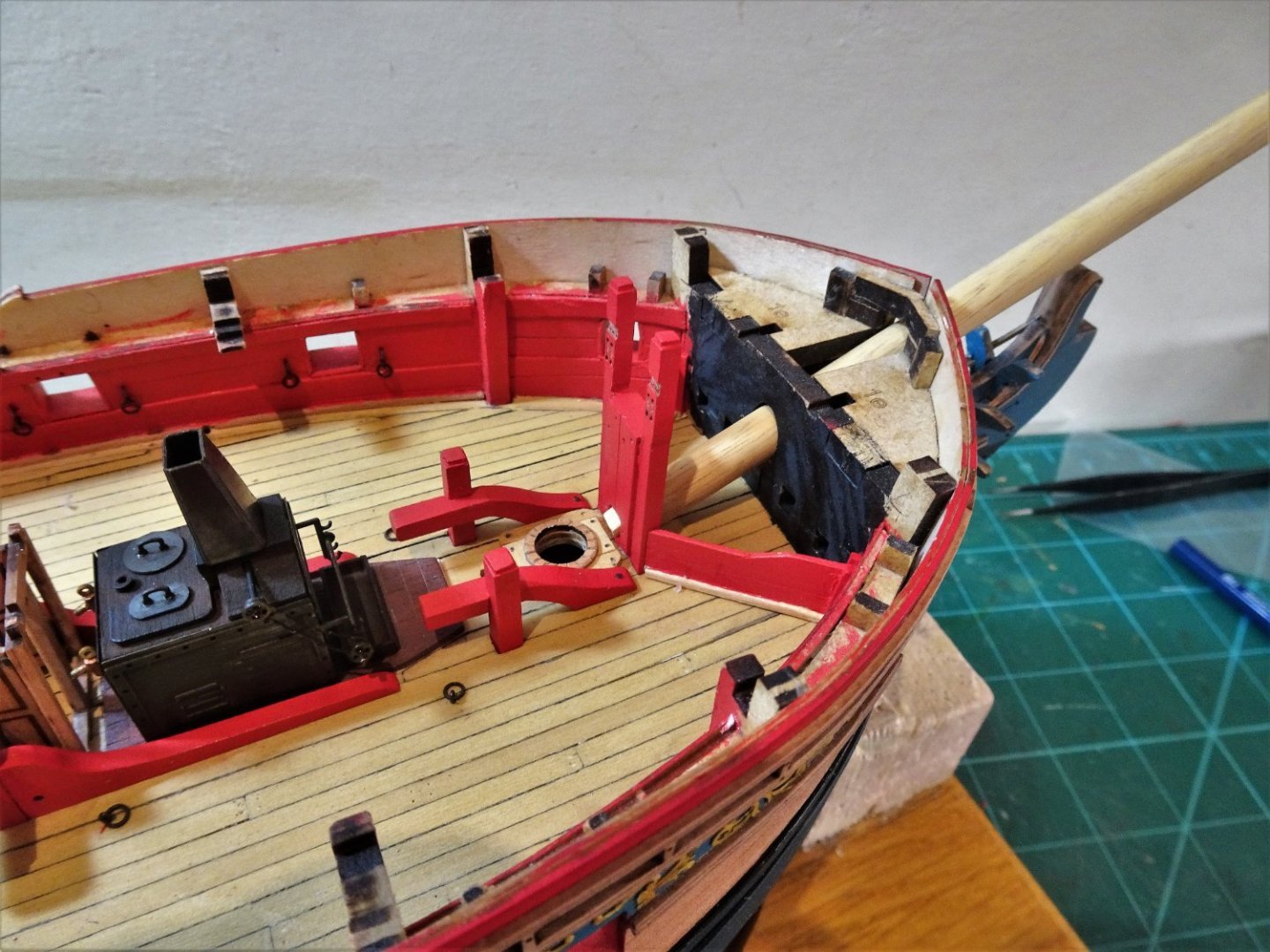
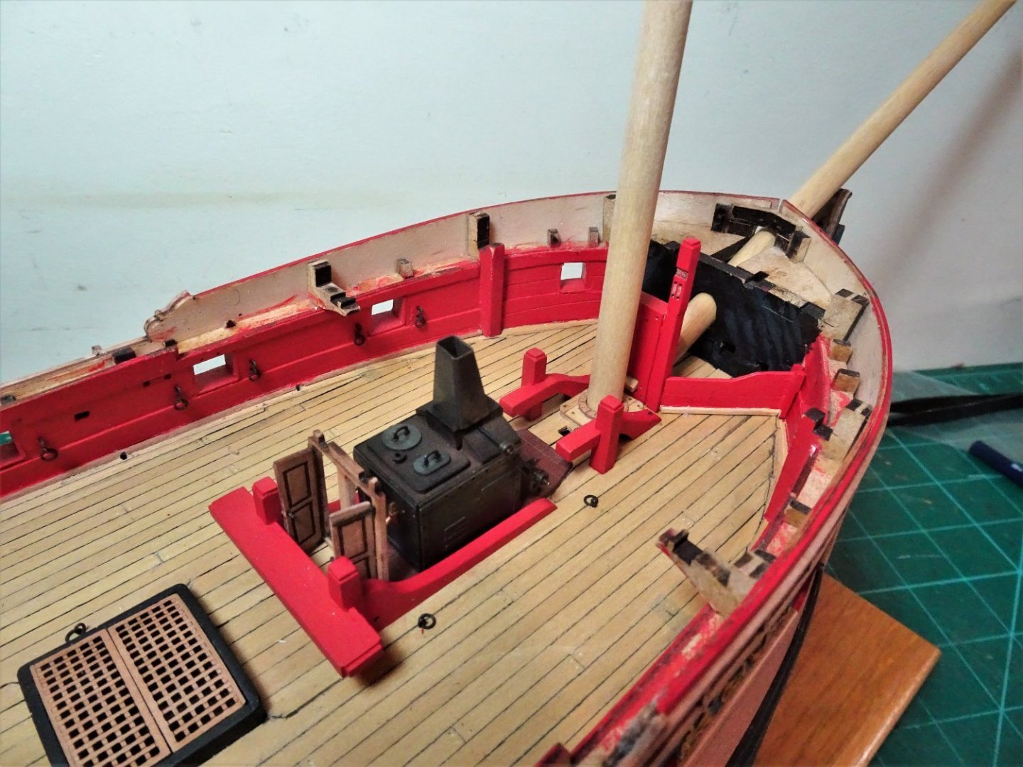
Post One Hundred and Two Bitts and pieces. 6261 This is a convenient point to fit the Main Ladderway, but the stanchions I will leave until later. 6263 I’m glad I took the trouble to shape and paint the support columns on the lower deck. A significant feature of the fore part of the Upper deck are the Riding Bitts. 6245 There are two sets of these; the aft Bitts which have a substantial cross piece, and the fore Bitts which sit beneath the Foc’sle deck either side of the Fore Mast. 6244 Shoe-horned between the aft Riding Bitts and the stove is the Galley door frame and doors. There is no doubt that these were a feature of ships of this period, but the position seems awkward and on a practical level one wonders why they are there. I suppose that when closed they do provide an element of weather protection, but little else to my 21st century eye. From a modelling display aspect the more immediate question is how much fitting this feature will further hide the pretty little stove a good few hours spent in the making of. The only way is to trial fit it. 6255(2) The view of the Stove end is not unduly obstructed. 6256 6258 … but the doors do impinge on the Riding Bitts. I’m not sure at this point if I will keep the doors but If I do I will varnish them rather than paint them red. The Marshall painting does show them fitted and painted red, but I think there is already an excess of red paint in that area. The Bowsprit step is also now glued into place. The step and the support legs of the Topsail sheet bitts are one unit in my build as the manger boards butt against the unit at the Upper deck level. 6265 I made the Manger boards back in posts 79/80, they now have to be put into position before the Foc’sle deck beams are fitted. 6268 6270 I can now move onto prepping the Foc’sle deck beams. B.E. 23/03/22

.thumb.JPG.a1c651adec2f145d5f67393c826ca20b.JPG)
- 857 replies
-
- 24
-
-
-
- Sphinx
- Vanguard Models
- (and 1 more)


.JPG.cb4159c2898778dd0a3e106a2fbec6a9.JPG)


.JPG.a6038317d15403bfa724ef3c66cd6887.JPG)


.JPG.1b3d6bd4159a4fbdd840c813739923f0.JPG)

.JPG.93fe857138e7eea35f2e520f9e51b142.JPG)
.JPG.142900fcf1286204cfab91ba0b3e57db.JPG)


.JPG.ef27be65290e51566cbcab511416b493.JPG)