
.JPG.ca33079f5815b861e67b9c2cccd37982.JPG)

Blue Ensign
-
Posts
4,576 -
Joined
-
Last visited
Content Type
Profiles
Forums
Gallery
Events
Everything posted by Blue Ensign
-
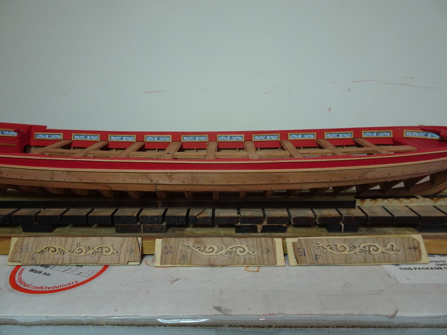
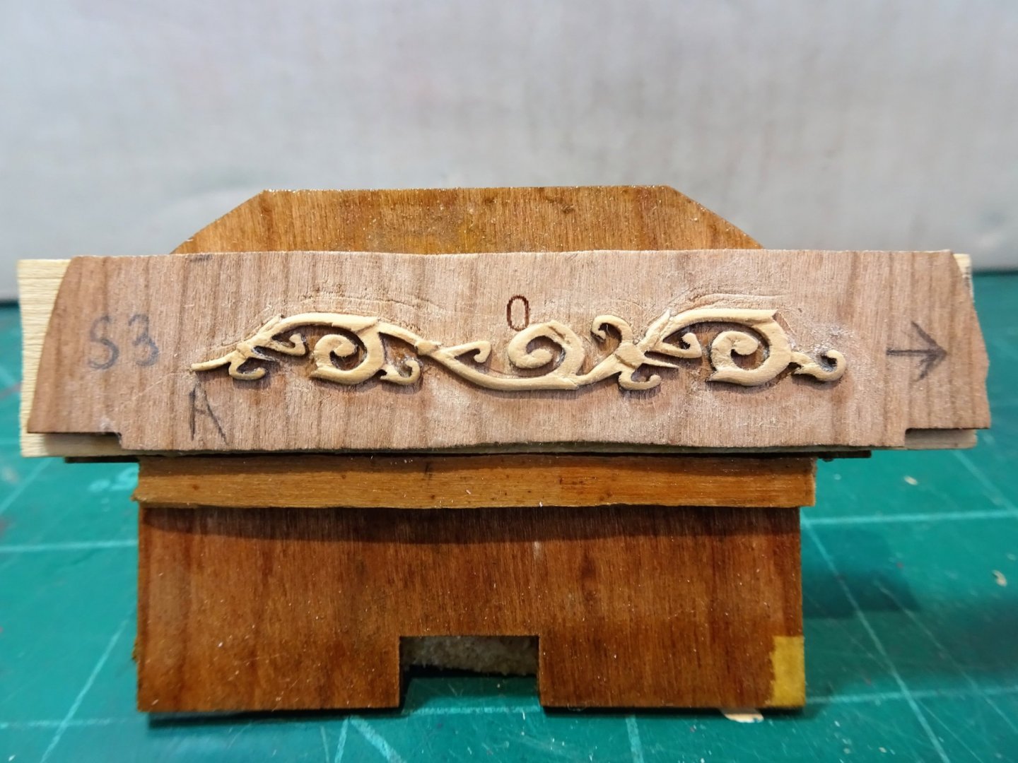
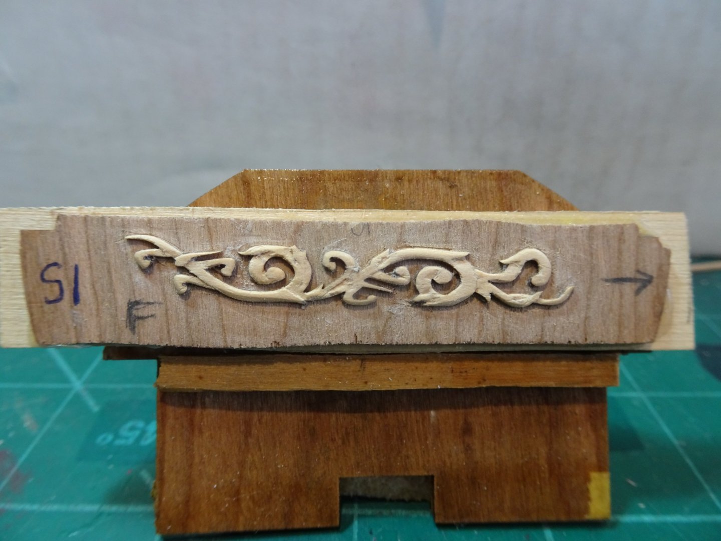
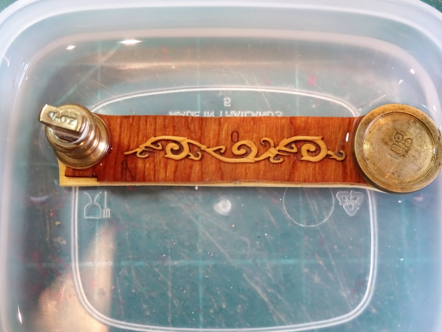
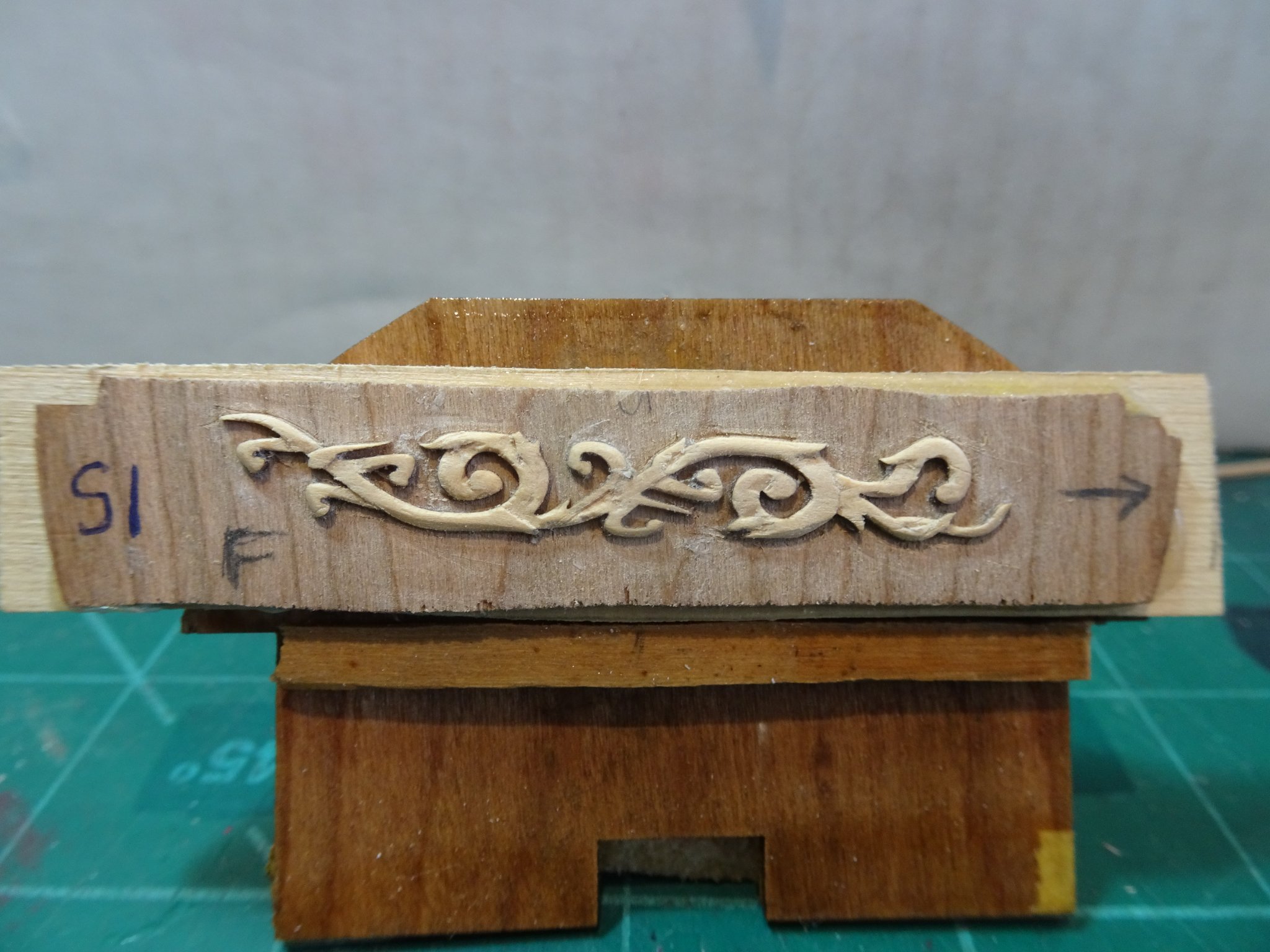
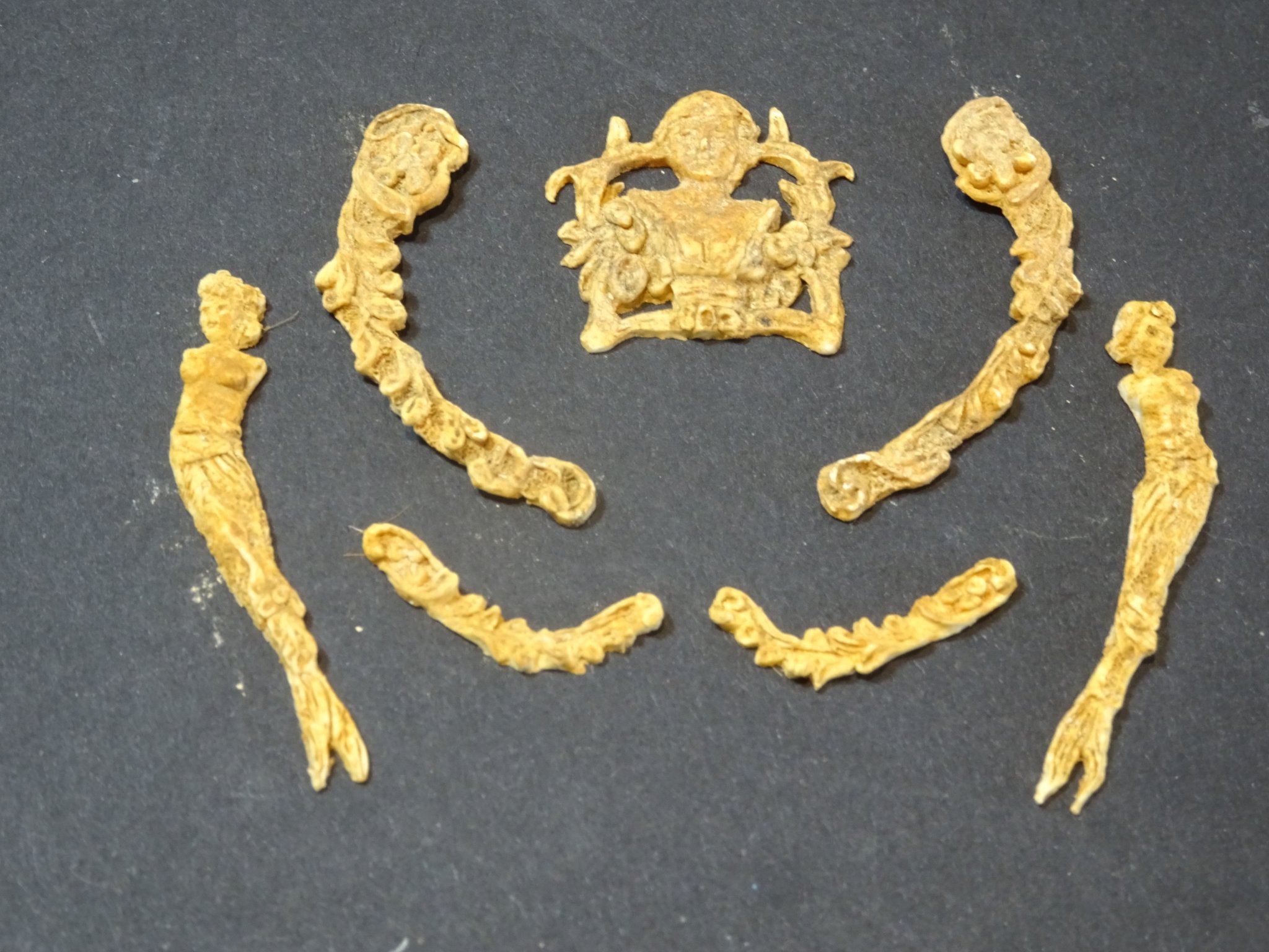
 Post Forty-0ne Acanthus whittling I have previously had a dabble at this which ended in a broken strip, and I put the process into abeyance whilst I got on with other stuff. Round two Having carefully attached the blanks to backing boards this time using a Pritt stick I hope for better results. 2545(2) I start by marking the stop cut lines and attend to these first. Micro chisels are used, and the direction of the grain is carefully noted. 2546(2) It is then a case of carefully paring a round onto the detail using a scalpel, fine sandpaper, and the edge of the chisel where required. 2542(2) I keep a copy of the Chuck’s examples in front of me as a reference. 2549(2) To ensure uniformity I prepared all three each side before I attempt to remove them from the backing. 2553 2552(2) 2551 Nearly ready for release, a little more smoothing and polishing. Portside decoration The same procedure for the Port side, but to ease interpretation of the carving lines I flipped the photo of the finished work provided by Chuck. 2611 As I write this post the first of the Acanthus carvings has been immersed in Isopropanol for some thirty hours and is still stubbornly hanging on in part to its backing. At this rate with another five to go I think I’ll probably lose the will to live! B.E. 26/06/21
.jpg.72750fa723c5c1760ce3e5b89ee8d451.jpg)
.thumb.JPG.8c59878ea7f4976f603e40e94d55225b.JPG)
.thumb.JPG.be8f23087a8eb57796b5775bf16402cb.JPG)
.thumb.JPG.3d46112794d5203a0311d9a4967a9860.JPG)
.thumb.JPG.21507c102b9b1cf071d6bdb65271246f.JPG)
- 185 replies
-
- 14
-

-

-
- queen anne barge
- Syren Ship Model Company
- (and 1 more)
-
Thanks Jason, I agree the figure needs (a lot) more work and in his present state he certainly won't make the cut. I have been in touch with the 3d model company who say they can do it but require me to provide the clothing, which is a bit problematical.🤔 I'll revisit the subject once I have completed the barge. B.E.
-
It looks magnificent Glenn, almost makes me regret not masting and rigging mine, but I did satisfy that urge on the smaller scale Alert. Great work.👍 B.E.
-
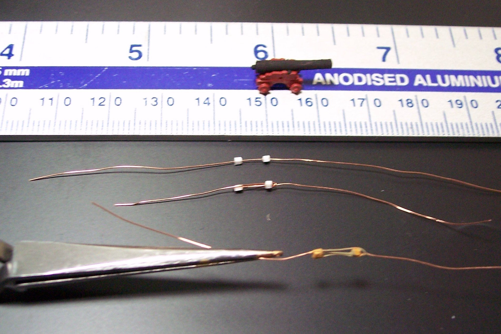
That looks like a system that would work, but can you get a block down to 1mm in length?, your prototype looks somewhat larger than that. Chuck supplies 2mm blocks in Boxwood which would save you the trouble, and those are really tiny. For my own humble efforts I simply looped fine wire around the block and superglued it to the sides, leaving a little loop at the top for the strop. at the bottom the wire was twisted and trimmed close. Not entirely authentic but sufficient for the scale involved. B.E.
-
1mm or smaller blocks, particularly iron stropped is quite a task. The closest I came to making 1mm blocks was for gun rigging on a 1:150 model. For this I used Evergreen styrene strip to form the blocks, it can be drilled and then cut to length, very fine copper wire was used for the strops. They are incredibly tiny to handle. B.E.

-
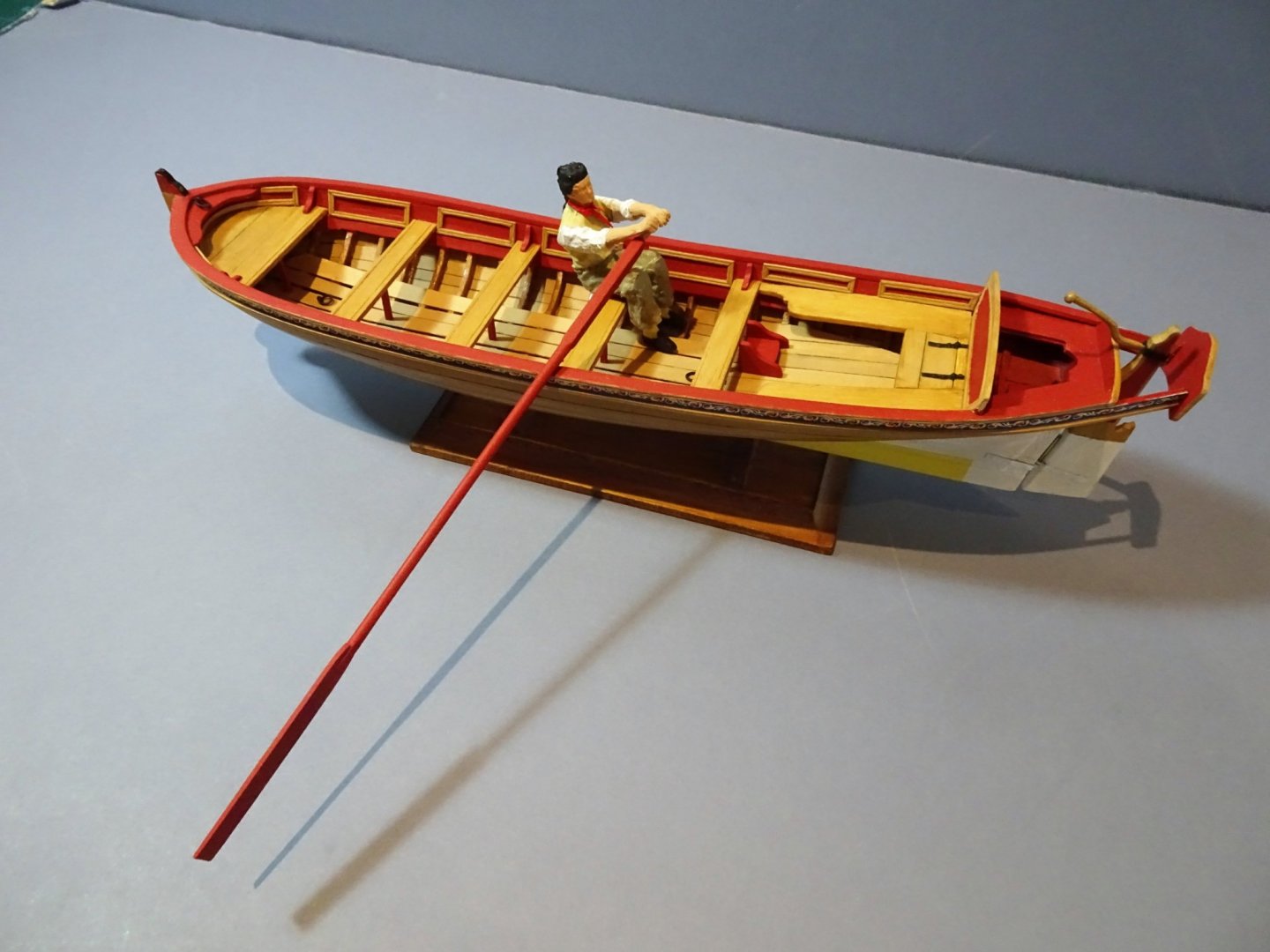
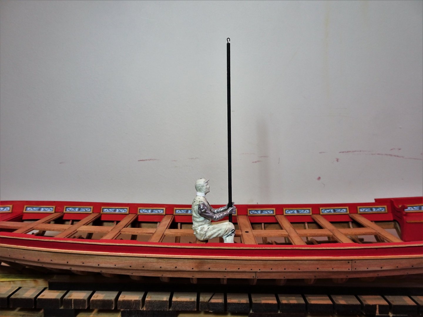
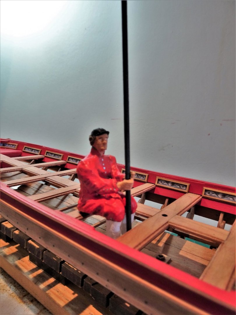
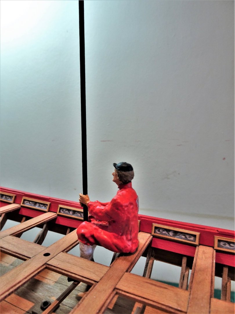
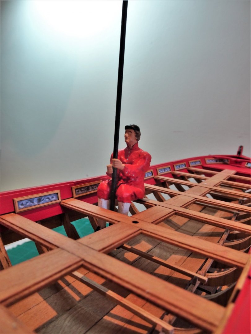
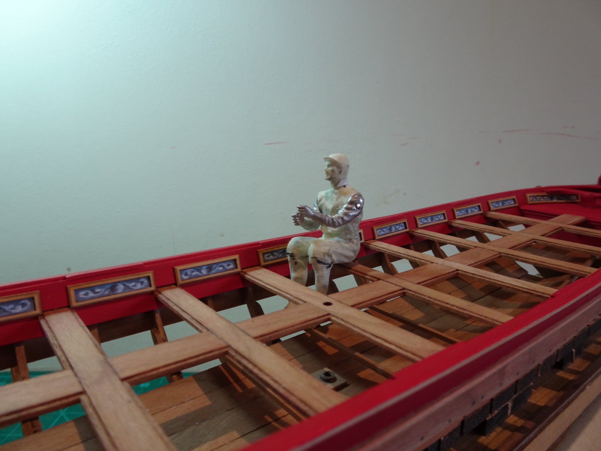
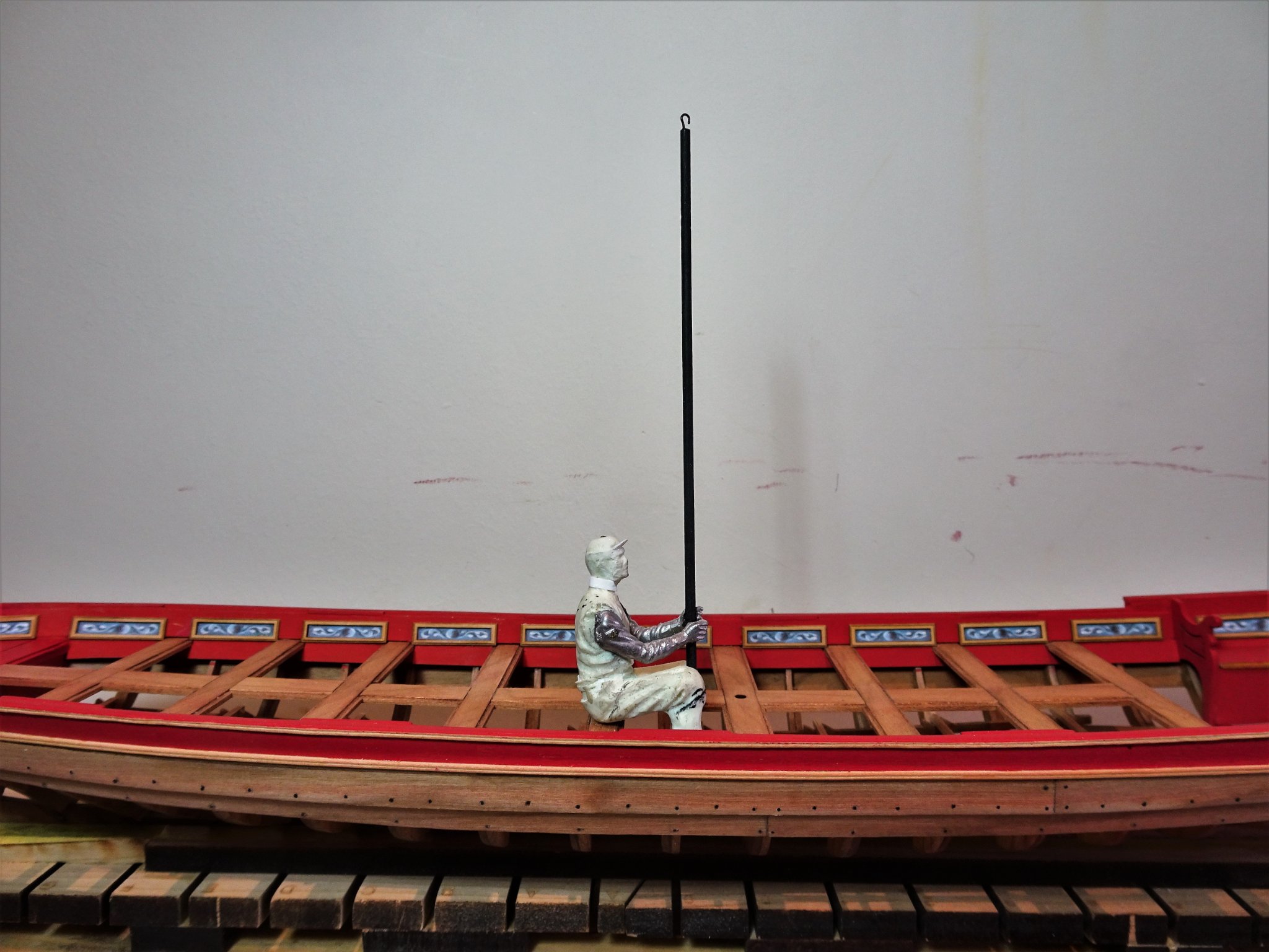
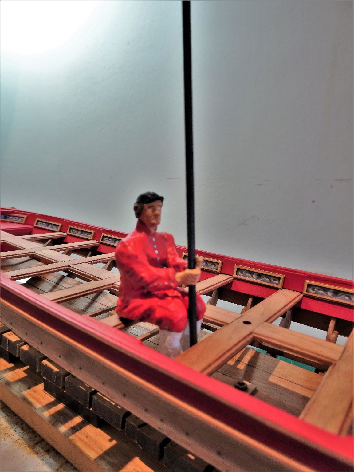
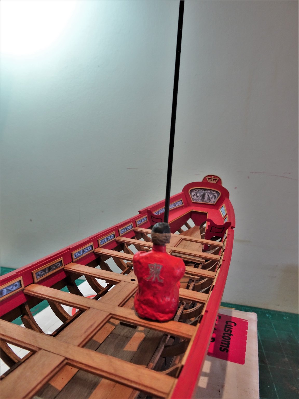
Post Forty The Royal Watermen Back from a break in Dorset and not yet ready to tackle the hull carving I decided to play around with a Waterman model. The doner piece is a 1:24 scale figure of an American Vietnam era soldier by Dean’s Marine. 0920 I used the same (modified) figure to represent a rower for my 1:24 scale Pinnace build. This time the dress would be different and I wanted to model the figure holding the oars in the vertical position. 2472 Early stage modification; the first action is to remove unwanted clothing and turn trousers into knee breeches. The figure is made of hard plastic and the Dremel was necessary to achieve this. 2479 The arms with this model are separate so it was not too problematic to position them correctly. It is then down to using modelling paste to create the uniform of the Royal Company of Watermen. A little research revealed that The Company of Watermen dates back to the 16thc and details of the uniform are available. It is from the ranks of this company that the Royal Watermen were chosen. A skirted scarlet tunic, coupled with breeches, and a navy/black cap. A prototype Royal Waterman is completed. 2533(2) 2521 I have reduced the Queen Ann monogram from the Barge kit to provide the plastrum on the back of the tunic. 2528 With the proper oars the arm/hand positions may need to be adjusted. 2526 I’m far from satisfied with the result but it does give me an idea of what is involved. 2519 Despite the antiquity of the uniform style, I’m not sure it looks right on the model, but at least he sits ok on the thwart. Time to stop messing about with this and get back to completing the model. B.E. 21/06/2021


.thumb.JPG.f32424c91ba92c124d47049a32dde0a8.JPG)
- 185 replies
-
- 16
-
-
- queen anne barge
- Syren Ship Model Company
- (and 1 more)
-
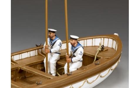
Ha, Ha, Ian, it turned out better than I thought it would, but I'm not expecting orders from any real women anytime soon. 😃 The oarsmen will be more problematic, and I will be discussing the issue with Modeldu. I want the figures dressed like this. but posed like this. I don't know how feasible it will be, or how expensive to produce them. ......... watch this space. 🙂 B.E.

- 185 replies
-
- 9
-
-
- queen anne barge
- Syren Ship Model Company
- (and 1 more)
-
Thank you Rusty and Jean-Paul, Chuck is a clever Guy, and I marvel at how he designed this kit, it is a great subject to work on. B.E.
- 185 replies
-
- 1
-
-
- queen anne barge
- Syren Ship Model Company
- (and 1 more)
-
Wishing you every success in this major step forward with Vanguard. Best Regards, Blue Ensign.
-
Nice sea base , perfect for a rolling Corvette. I liked this kit so much I built it twice, once as Bluebell, once as Snowberry, it was fun doing the modifications necessary for Snowberry. Great start. 👍 B.E.
-
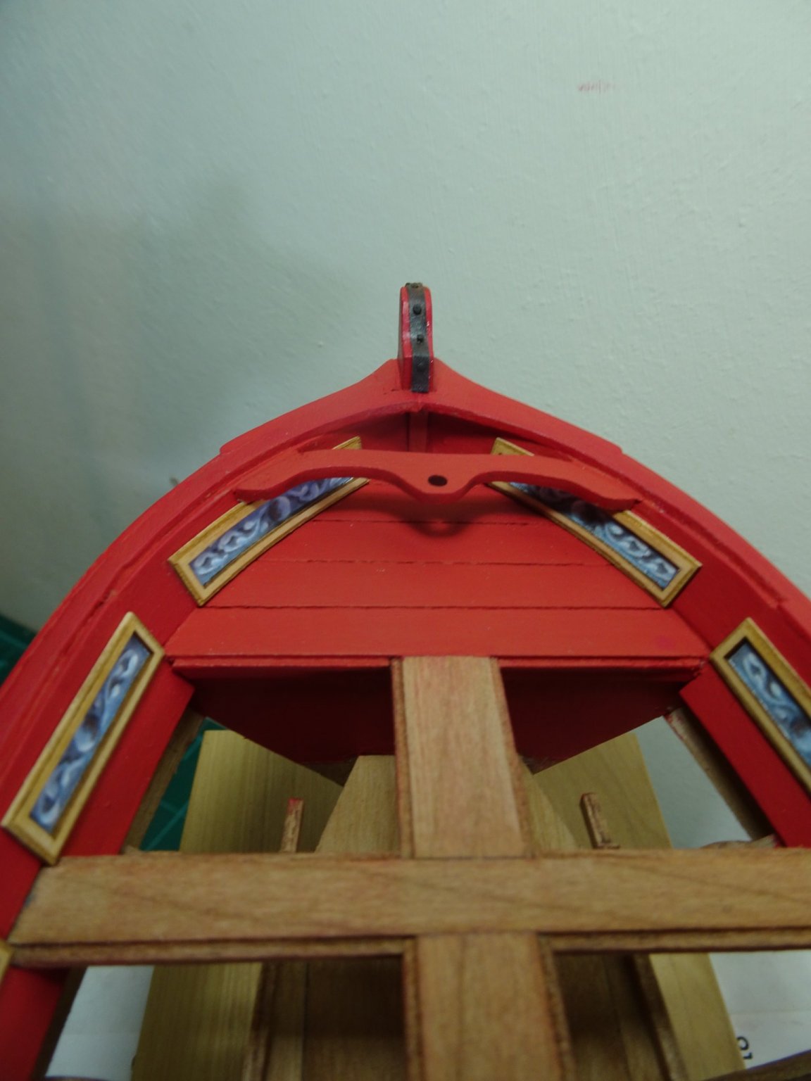
Thank you Chuck, better than I had imagined I could achieve, which is not necessarily saying much. 😉 Post Thirty-nine External decoration and the dark art of weathering powders. The first thing I add is the ‘iron’ strap that runs over the stem, rather than use wire to represent the bolts, I used fine pins. 2298(2) I rather like the resin impregnated fibre board that Chuck uses for the purpose, so much easier than the blackened brass strip, I would otherwise use. 2292 A light dusting of dark brown weathering powder and a realistic impression of iron is achieved. I next attended to the provided resin decorations using weathering powders, as suggested by Chuck. I am using a combination of Revell, and Vallejo powders, Light Yellow Ochre, Sand Yellow, Snow White, and Dark Brown. 2262(2) Once the coating had been applied the piece was lightly sprayed with fixative. 2264(2) 2280 The full set. 2303(2) The Queen Anne bust is glued into place on the Flying Transom. 2338 I found fixing the Bow decoration a little tricky, not least because of the marring of the paintwork once again, as I secured it into place. 2337(2) 2339(2) I will almost certainly continue to tweak the highlighting and shading of the resin decorations up to completion of the model. I will leave the remaining decorations until I have trialled the fit of the acanthus leaf friezing along the stern sheets, which I must now get back to whittling. B.E. 04/06/21
.thumb.JPG.be8edfdce93a30e5638d71588240b2d2.JPG)
.thumb.JPG.2b944512387f80d56f5a06bf9ca3fd93.JPG)


.thumb.JPG.b7969d6f387775b177f7a7a760cdc3f6.JPG)
.thumb.JPG.0e0a1bb0895ec1ba258c46ea8d49efca.JPG)
.thumb.JPG.6609df37bb3d977ba4762814bc6a4e5f.JPG)
.thumb.JPG.75321f841ccadafa3803143485de457d.JPG)
.thumb.JPG.0229e42e34cac46febf7cca839d42ed6.JPG)
- 185 replies
-
- 19
-
-
- queen anne barge
- Syren Ship Model Company
- (and 1 more)
-
Excellent work Richard, looks great. 👍 B.E.
-
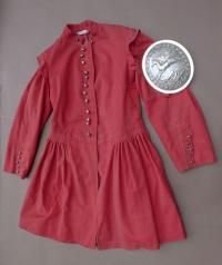
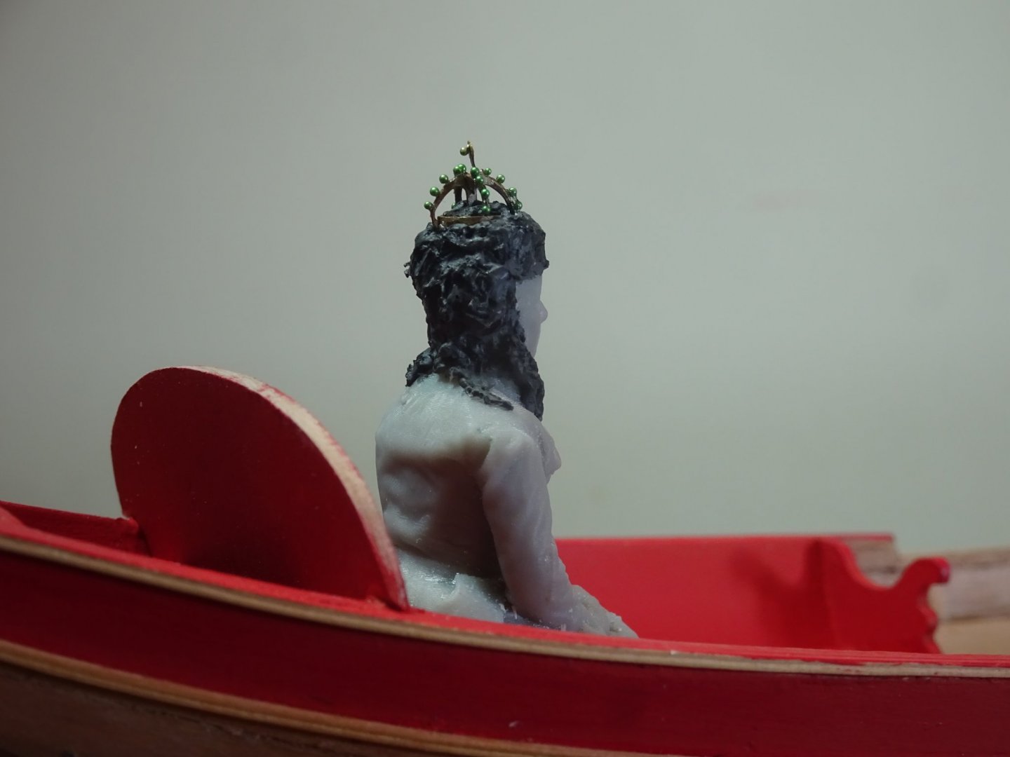
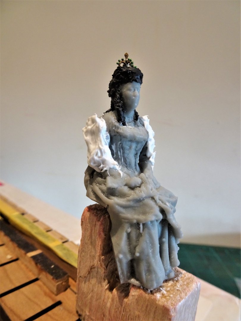
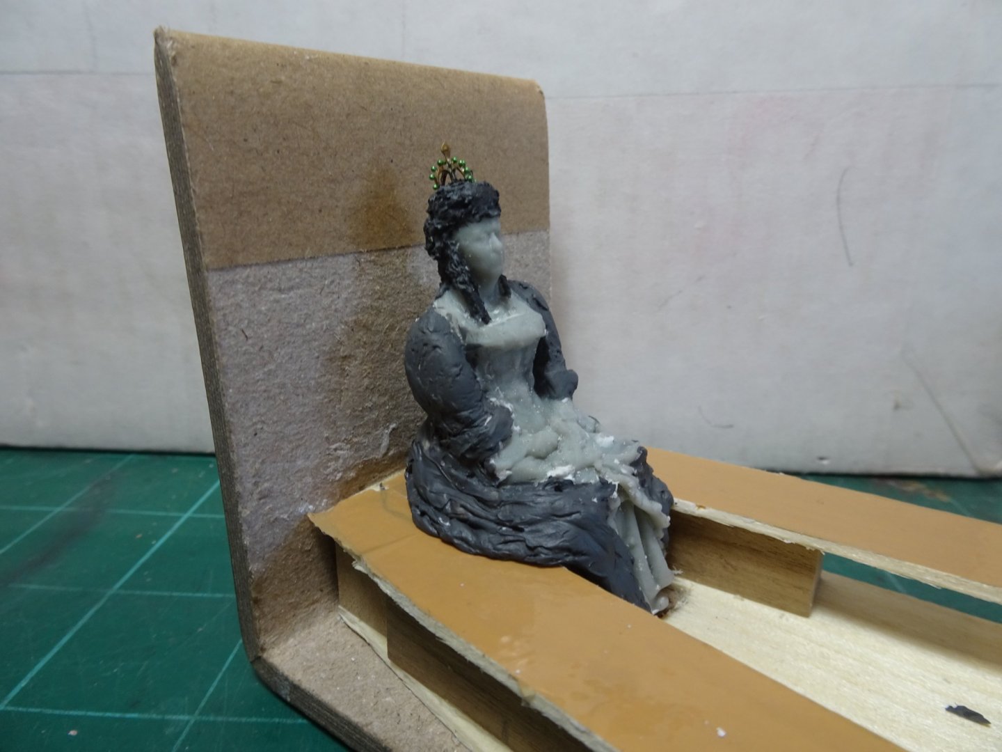
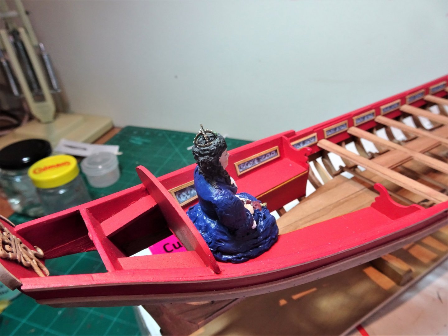
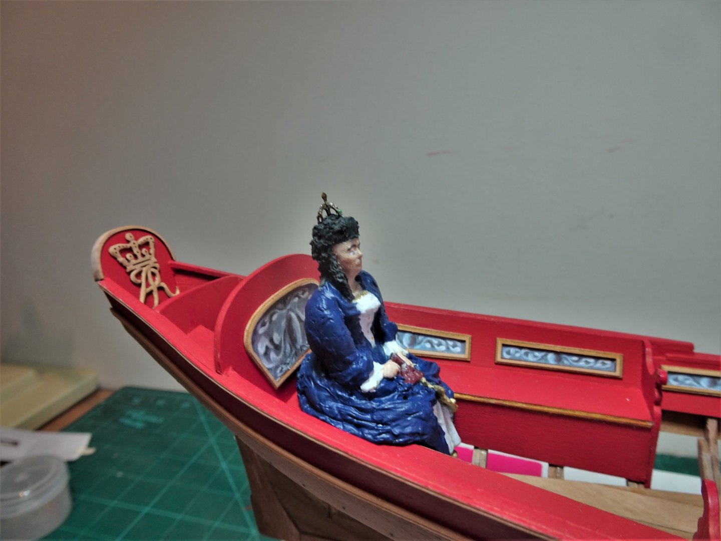
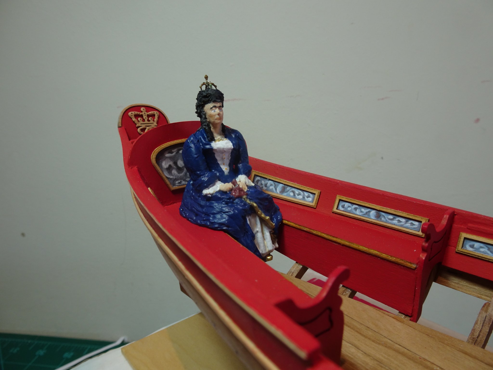
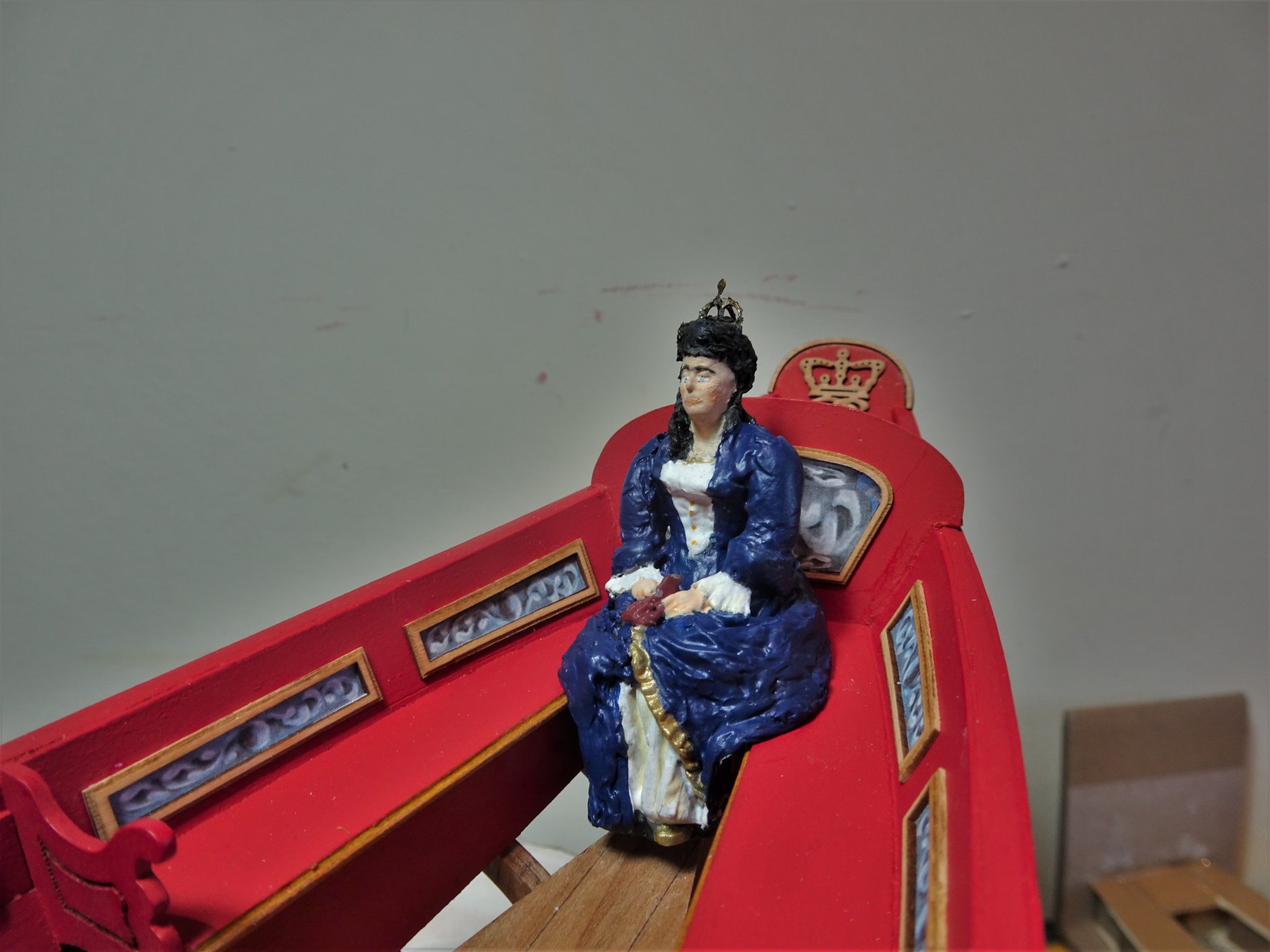
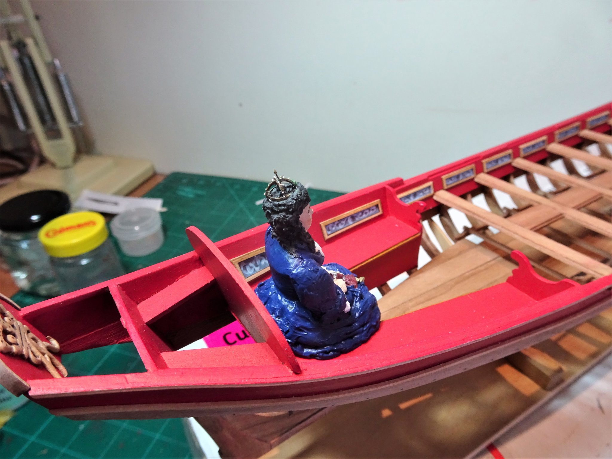
Post Thirty-Eight The making of a Queen. (Sort of) Before I continue with the Barge I re-visit Queen Anne. 1850 Previously I had modified the head to reflect an 18th century hairdo, added a coronet, and sculpted the skirt area to fit the barge seat. 2201 Primarily the sleeves need to be made looser, again using the modelling paste to build up the fullness. Layers are built up and as the paste starts to set it is shaped and smoothed. Early Eighteenth century dresses were close fitting at the waist but very full in the skirt and often hooped. The model as presented is quite good with the folds gathered around her but requires a little more fullness spread out over the seat. To achieve this, I needed to make a mock-up of the bench seating of the barge so I could form the folds around her. Parcel tape covers the benches to prevent the paste sticking. 2205(2) The idea is to get sufficient paste around her that can be shaped and smoothed, and the figure removed once the paste firms up a little. 2215 The built-up areas are primed. I have dressed her by reference to styles of the early 18th century. In my mind for a trip upriver to Hampton Court Palace, a favourite of the Queen. 2260 2248 Acrylic paints were used, and altho’ I belong to the Blind man on a galloping horse school of figure painting she looks ok from normal viewing distance, better than the macro would suggest. 2259(2) 2258(2) 2257 2252 2250 2261(2) I will leave the tricky question of the Bargemen until later. B.E. 01/06/21
.thumb.JPG.e0b862b678b2a3071a07b6de3fbb7be3.JPG)

.thumb.JPG.6faa4187e14e6462cd4e1ffaf214fa28.JPG)
.thumb.JPG.b250f21b8c4b15065274b9a3695fc443.JPG)


.thumb.JPG.77c99a479a7d7cc1a6543141d56338d6.JPG)
- 185 replies
-
- 19
-
-
- queen anne barge
- Syren Ship Model Company
- (and 1 more)
-
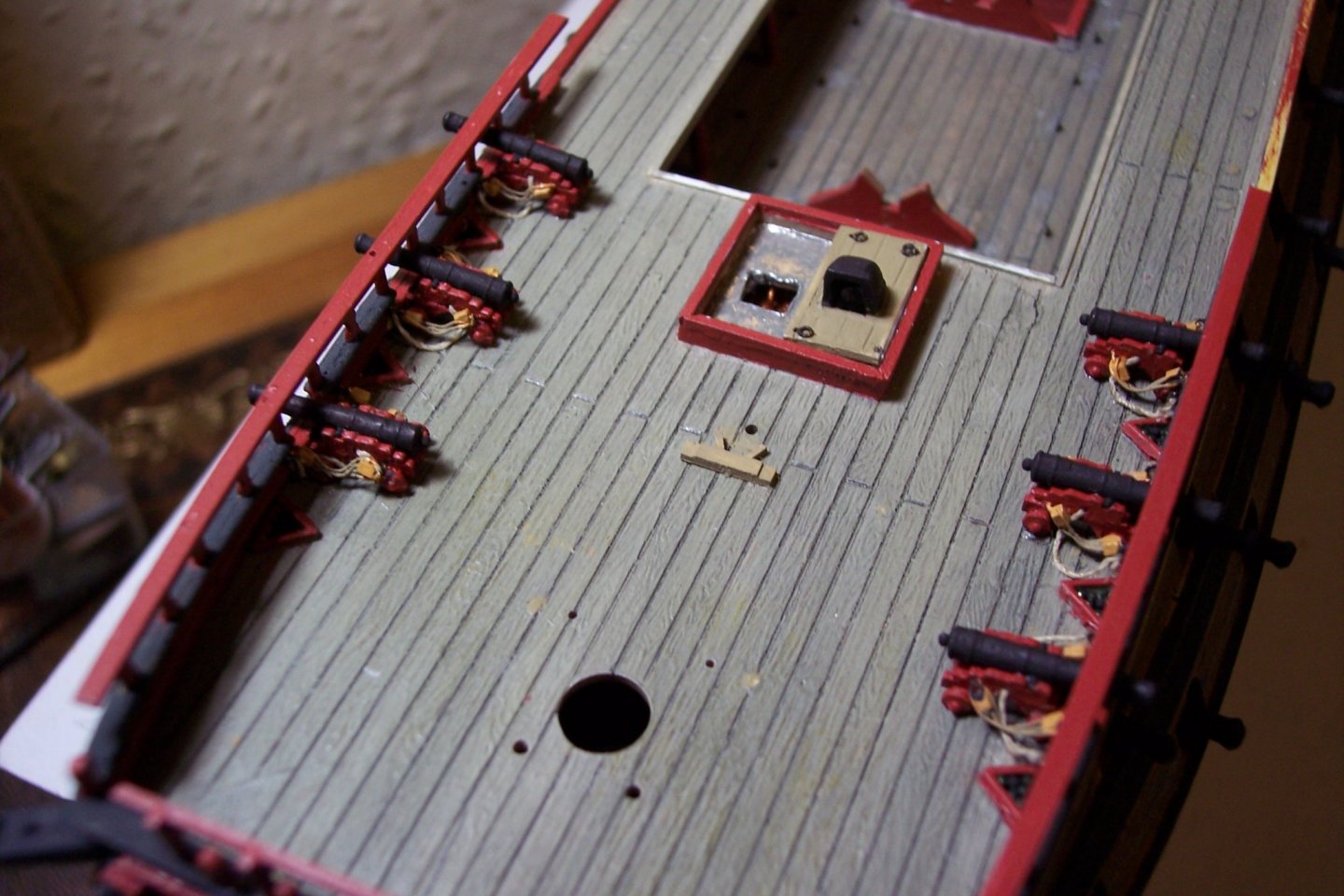
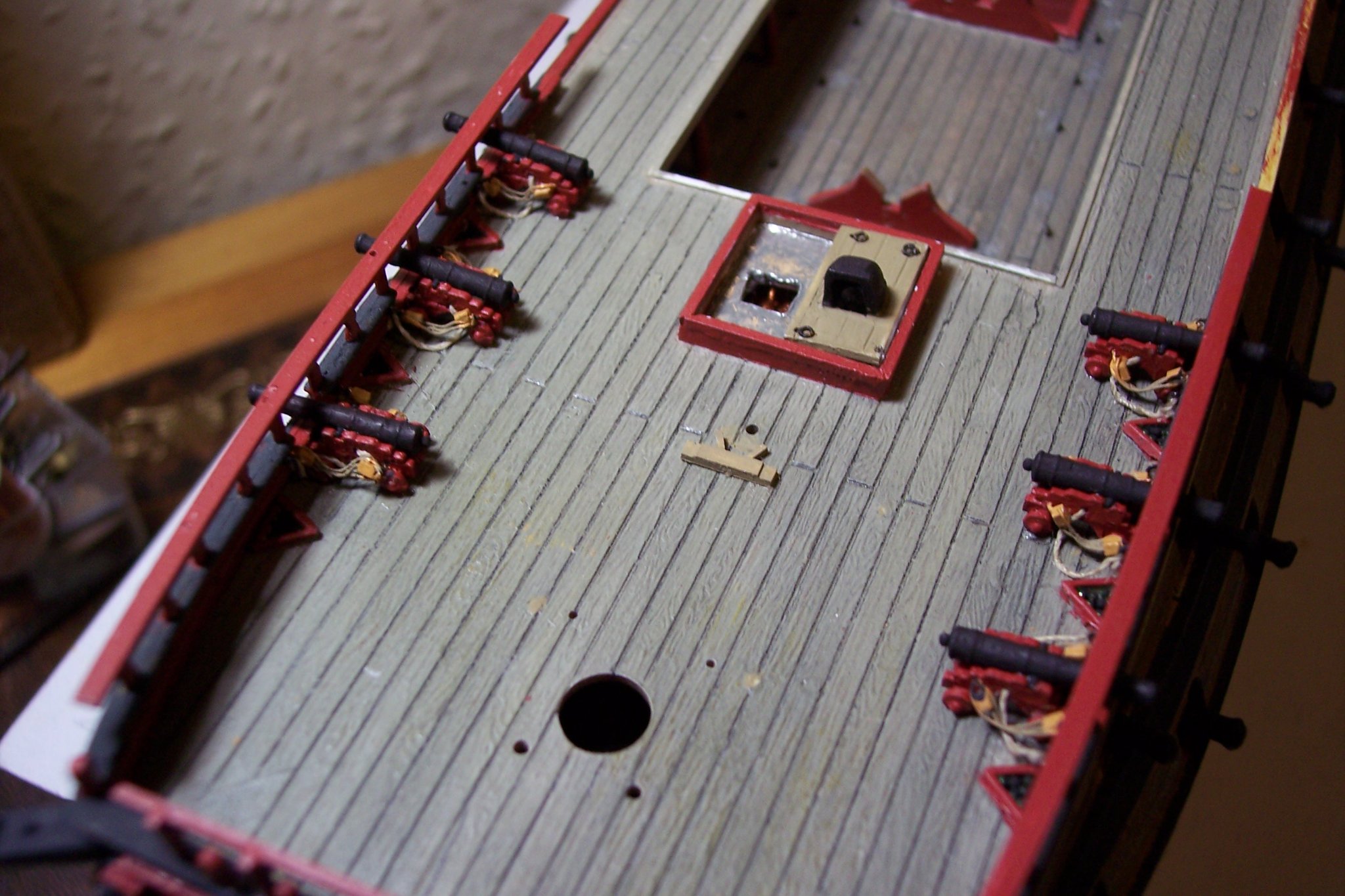
A fine looking model with great presence, the deck shots give a wonderful impression of how crowded these small vessels were. Very well done.👍 B.E.
- 950 replies
-
- 1
-
-
- syren
- model shipways
- (and 1 more)
-
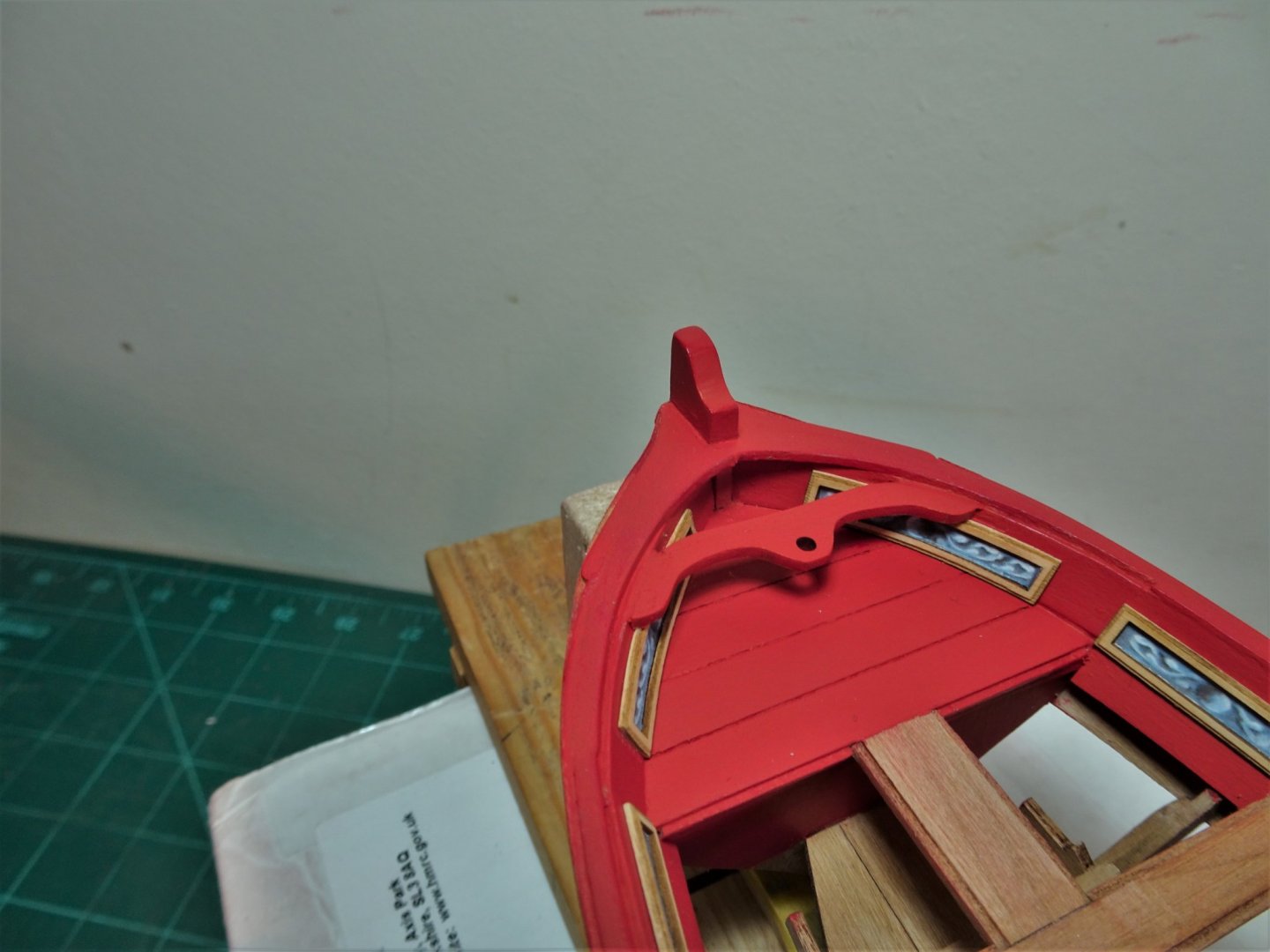
Thank you Hubac, I did scrap a couple of them, but fortunately Chuck had the foresight to provide a few spares for us finger fumblers.😀 Post Thirty-seven Completing the inboard works. The Bow bracket is completed. 2131 Still to drill the socket in the Fore deck to receive the Flagstaff heel. The final part to assemble is the step down into the stern sheets. 2179 A simple assembly job of four pieces. 2183(2) I added the Royal Monogram to the Flying transom, and the Boxwood moulding. The Monogram I whittled earlier, and a coat of wop was applied before I fixed it in place. Again, micro spots of ca were used for the purpose. I also applied a coat of wop to the Boxwood frieze panels using a fine brush. Three months work has brought me to completion of the internal work on the model, with the external decoration and fittings now to do. Some photos to mark this milestone in the build. 2159 2161(2) 2164(2) 2185(2) 2186(2) 2191(2) 2192(2) 2198(2) B.E. 29/05/21

.thumb.JPG.b6d22ce352c37467c35a0e55819ba088.JPG)
.thumb.JPG.8e918a303749b925d4b041aa9255c245.JPG)

.thumb.JPG.89cdf7e8f7774ab5866480bfd7518291.JPG)
.thumb.JPG.58ba10b88374beaaf66179f06bac8720.JPG)
.thumb.JPG.d7ed34bacbda7b897d18b6f4084d7351.JPG)
.thumb.JPG.ddb01fb80223a9d53e15cdbcc1890627.JPG)
.thumb.JPG.688b857168762069f876bd92a89023ae.JPG)
.thumb.JPG.8f7894bc804771780cd17fc926555fe5.JPG)
- 185 replies
-
- 13
-
-
- queen anne barge
- Syren Ship Model Company
- (and 1 more)
-
Thank you Chuck, I am impressed by the thought you have put into the design of this model, it is a joy to build. I can't imagine that new batch of kits will hang around long. 🙂 Regards, B.E.
-
Post Thirty-six Applying friezes. Before I started I re-sprayed the friezes using Windsor & Newton fixative. 2079(2) An improvised spray booth. 2077(2) A kit was put together to aid this rather tedious task. 2080 Diluted pva applied with fine brush was used to glue the friezes in place. A centre blank attached to a toothpick is used to press the friezes into place. 2091(2) The addition of the friezes transforms the look of the barge. At this point I add the support bracket for the bow Flagstaff. This probably also doubles up as a hull brace. 2085(2) Quite a tricky little beggar to fit, ensuring it is central and sits as best it can down on the bow frieze panels. Even so a touch of filler is required to smooth out the edge joins. 2083(2) I ran a bead of diluted pva along the joins. Once that has cured, I will complete the filling and paint the bracket. 2084 2089(2) Best part of a day to see this task completed, time to crack open the Merlot I think. 🍷 B.E. 26/05/21
.thumb.JPG.4c9b117a0694b91f89fc8e4411438b15.JPG)
.thumb.JPG.337a573d28dc642df606dbfb7a83a45d.JPG)

.thumb.JPG.cef02d4aa800f8c05237bbfc61b2e9ca.JPG)

.thumb.JPG.4f72826bfa0074c5cdc3c6b4191eb64b.JPG)
.thumb.JPG.d2b649343926dbf2e8b4a93b3c77d5aa.JPG)
.thumb.JPG.5b57ea007cbf225d31a33d6321fc3004.JPG)
- 185 replies
-
- 17
-
-
- queen anne barge
- Syren Ship Model Company
- (and 1 more)
-
Thank you Allan, the simple answer is I didn’t. I used two melt points on the brass elements, but the glass seed beads were ca’d onto the brass. I’m not sure they will remain as small as they are they still seem a tad over-scale. The crown was actually constructed from the two parts of a small brass etched grapnel trimmed to suit. Regards, B.E.
-
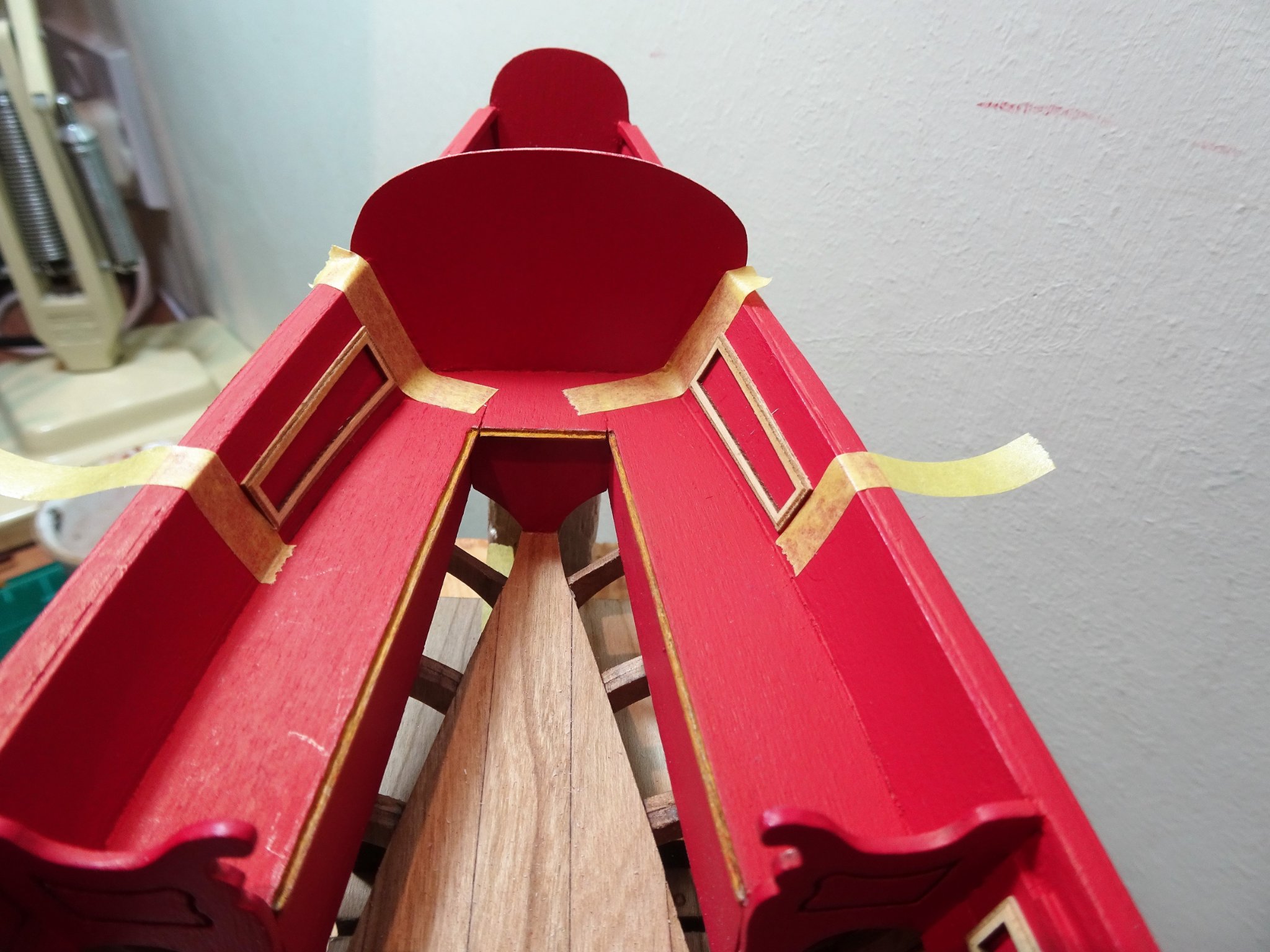
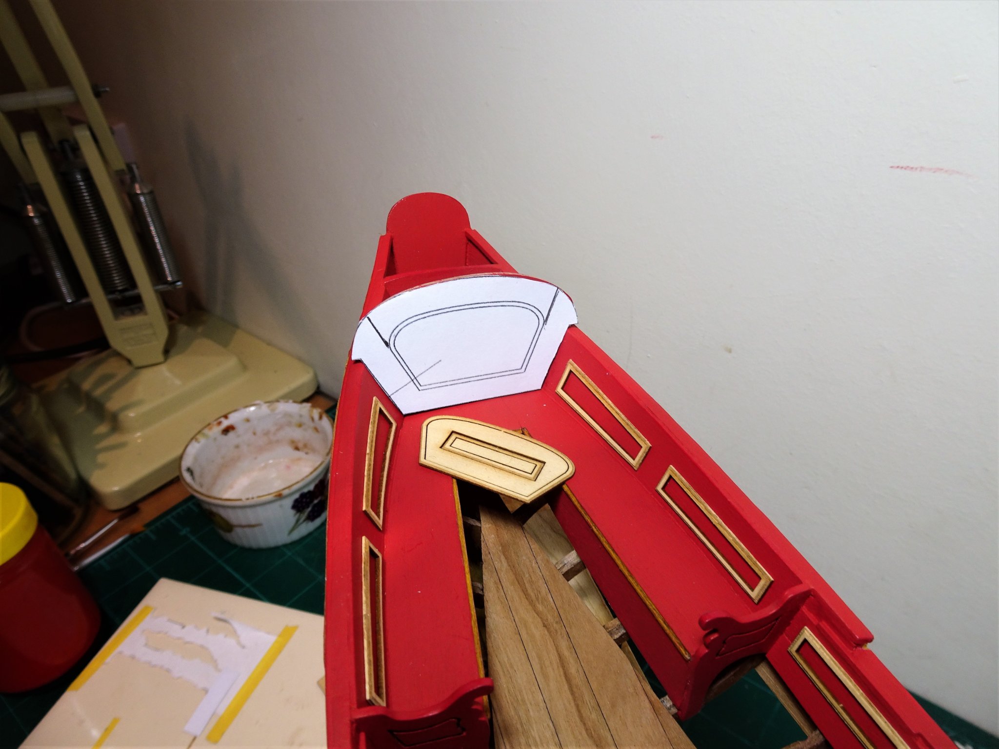
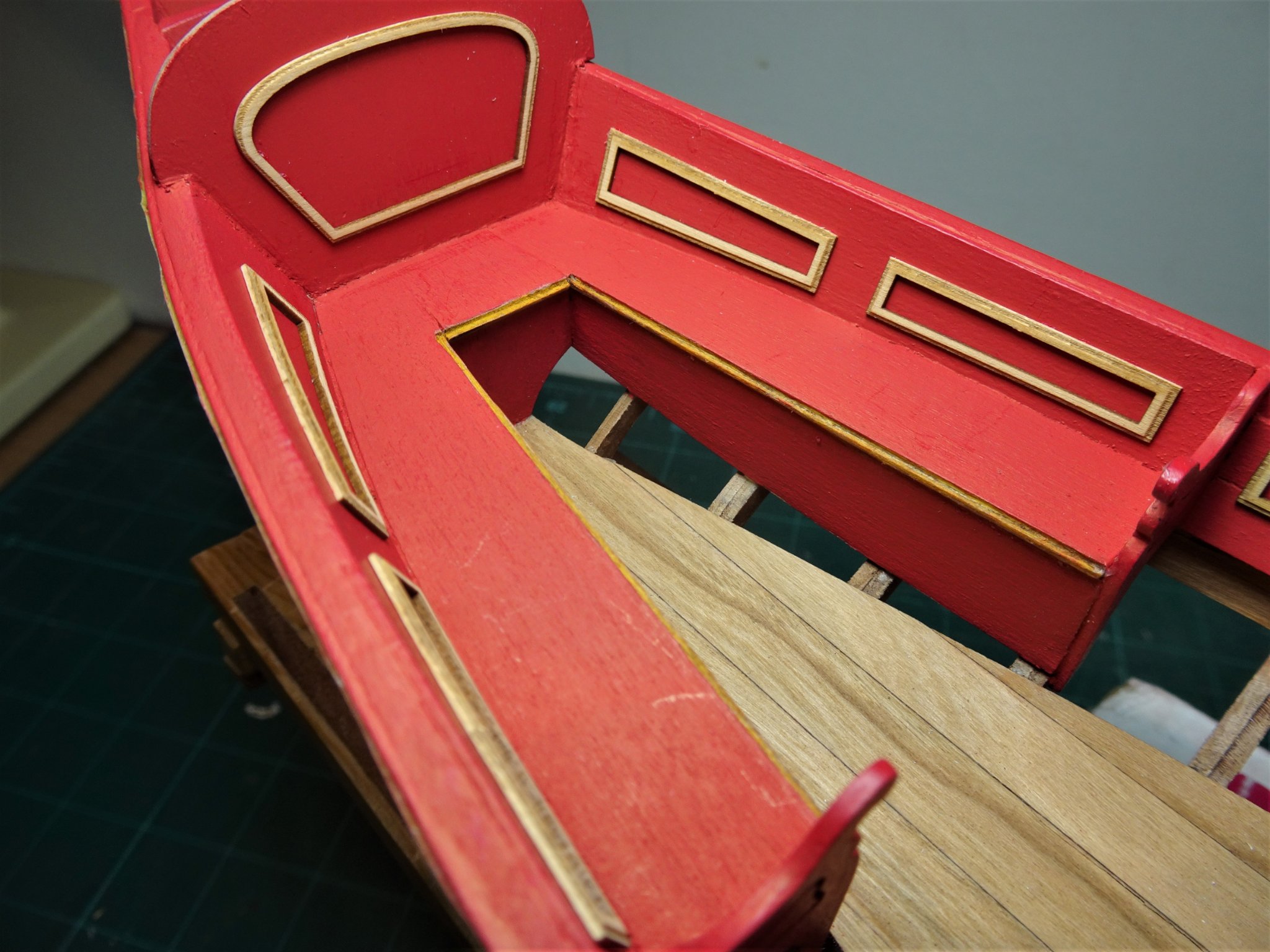
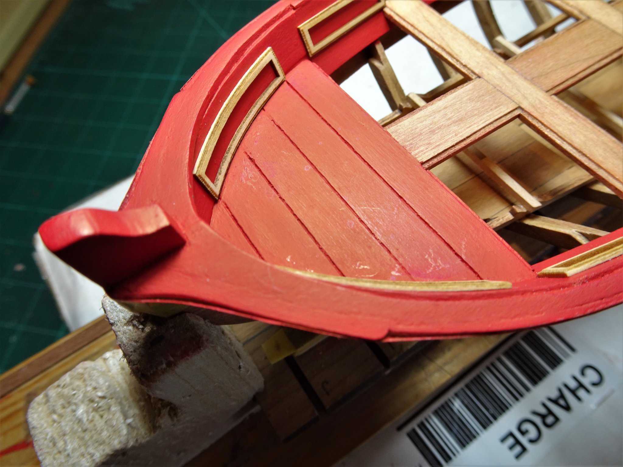
Post Thirty-five Adding the Decorative panels. Chuck emphasises the fragility of these fancy little frames, but at least had them laser cut saving a lot of time and effort. I well remember forming the mitres for the panels on the 1:48 scale Pinnace and have even less fond memories of doing the same for the 1:64 scale Pinnace I made for Pegasus. The first issue that comes to mind is how do I glue these frames to the inboard planking without marring the paintwork that I have just spent hours fiddling with. The majority of pieces fit simply enough guided by the thwart edges, but I can’t afford to have excess glue squeezing beneath the outer edges or be faced with any form of hard-edged clean-up. 2056 To fix the frames I decided on minute spots of ca applied to the back face. With the bottom edges sitting on the thwart the question of moving around to fix position does not arise. As advised by Chuck I did minimal cleaning up of the frame edges, using the centres to support the piece whilst light pressure was applied. 2058 I wet the curved bow pieces for a few minutes, clamped them into place, and applied heat for a few moments. This was sufficient to de-stress them before gluing into place. The panels that gave me the most trouble were those for the Sternsheets. There are no fixed points of reference for height and distance, and the shape and dimensions of the Boxwood patterns differed slightly from those shown on the plan. 2061 I used Tamiya tape to define the inboard position of the larger frame, (7mm) and the distance between the two frames, (6mm). 2059 A 1.5mm thick piece of scrap wood was used to get a uniform height above the benches. 2064 The final item is the Frame to fit on the Transom, to get this centred I used a cut-out from the plan. 2073 Careful as I was, the paintwork was marred a little as can be seen on the benches here, but I managed to get thro’ this exercise without any breakages. 2074 Further evidence of paint scuffing on the Fore deck. 2072(2) 2068(2) 2070(2) A small repair to the paintwork and then the panel friezes to fit. B.E. 25/05/21

.thumb.JPG.c9c82595b882b6042015f7692cc33cdd.JPG)
.thumb.JPG.e8b57d695f7997c515508b0a14d1cced.JPG)
.thumb.JPG.b34536eb6f3fd0e4262d488a606358ae.JPG)


- 185 replies
-
- 14
-
-
- queen anne barge
- Syren Ship Model Company
- (and 1 more)
-
Coming along nicely Paul, a fine job on the hull planking. 👍 B.E.
- 28 replies
-
- 1
-
-
- Amati
- Lady Nelson
- (and 2 more)
-
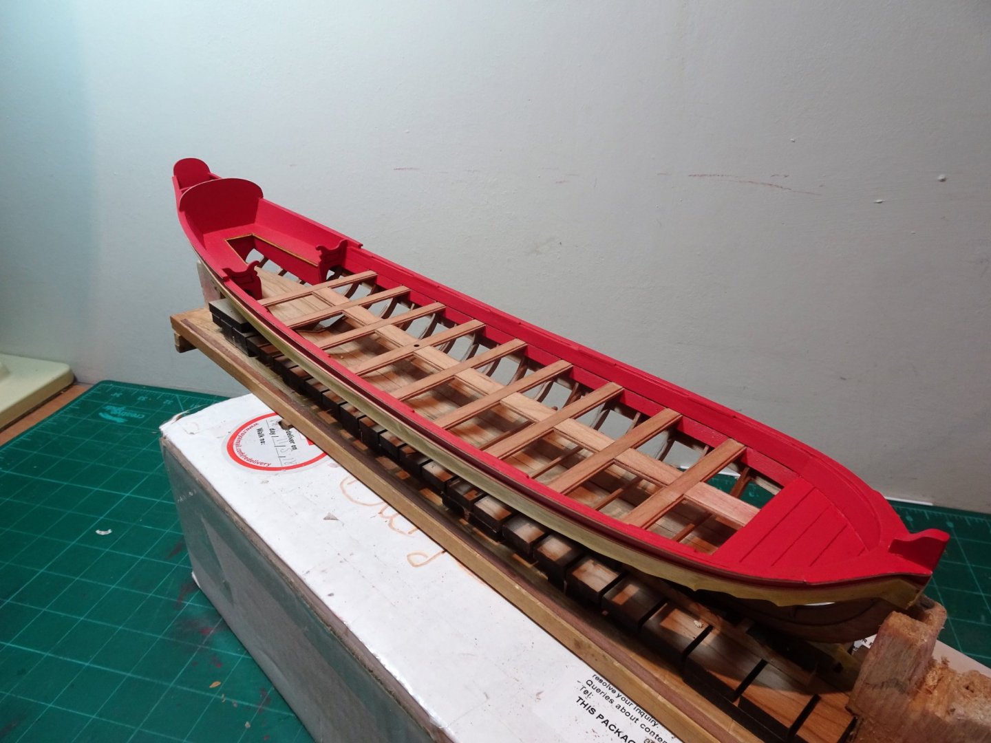
Post Thirty-four Paint, sand, fill, and repeat. Any obvious areas needing filling are attended to and a first paint layer applied. This has the effect of revealing multiple deficiencies, not entirely unexpected, so it’s a case of sand, fill, and repeat. The result, better, but not there yet. The following control photos are the result after two further sand and fill sessions. 2055(2) 2054(2) 2053 2051 2049(2) One thing I should have realised is that the paint dust on my fingers has a tendency to mar the bare Cherry wood hull so it was necessary to tape over the woodwork. I should have done this at the outset. 2050 Painting the inboard panels and capping rails has given me a chance to get a better appreciation of how leaving the thwarts as varnished wood will look in the overall scheme. 2048 Time to repeat the sanding process, but this time I am using a light touch and fine grade paper. B.E. 24/05/21
.thumb.JPG.619cf13bd9d09cccf4cff902321afcfa.JPG)


.thumb.JPG.59193793aabf2452bb4d702b338a3695.JPG)
.thumb.JPG.af5cfb40cf93f058cb285c199009e2f3.JPG)
- 185 replies
-
- 11
-
-
- queen anne barge
- Syren Ship Model Company
- (and 1 more)
-
That looks wonderful Chris, a serious temptation.👍 B.E.
-
Thanks Glenn, I went into a little more detail on fitting the bow section internal planking, as I thought it may help those following on. Chuck didn't have any photo's of this part of the build to include in the Instructions. Regards, B.E.
-
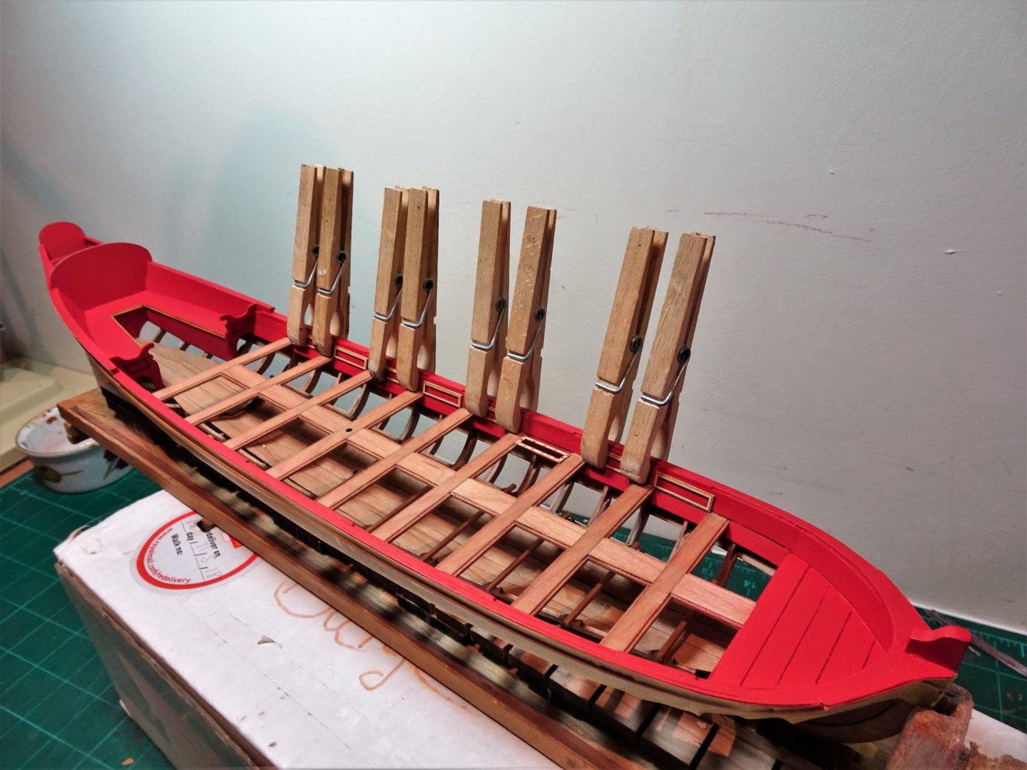
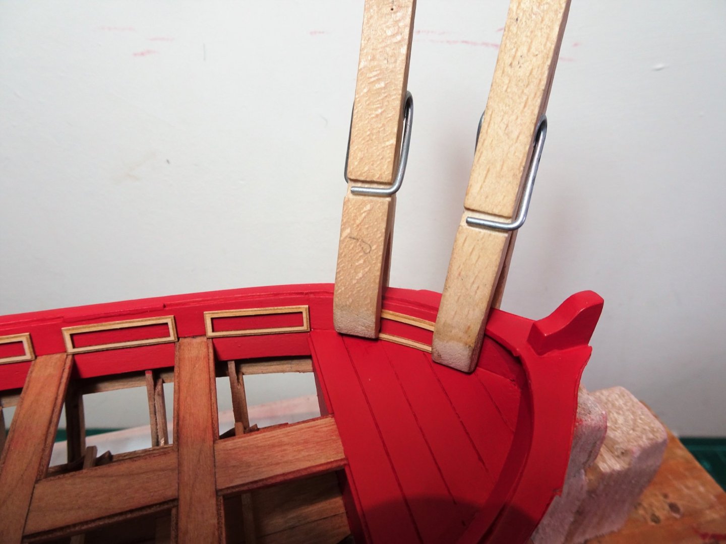
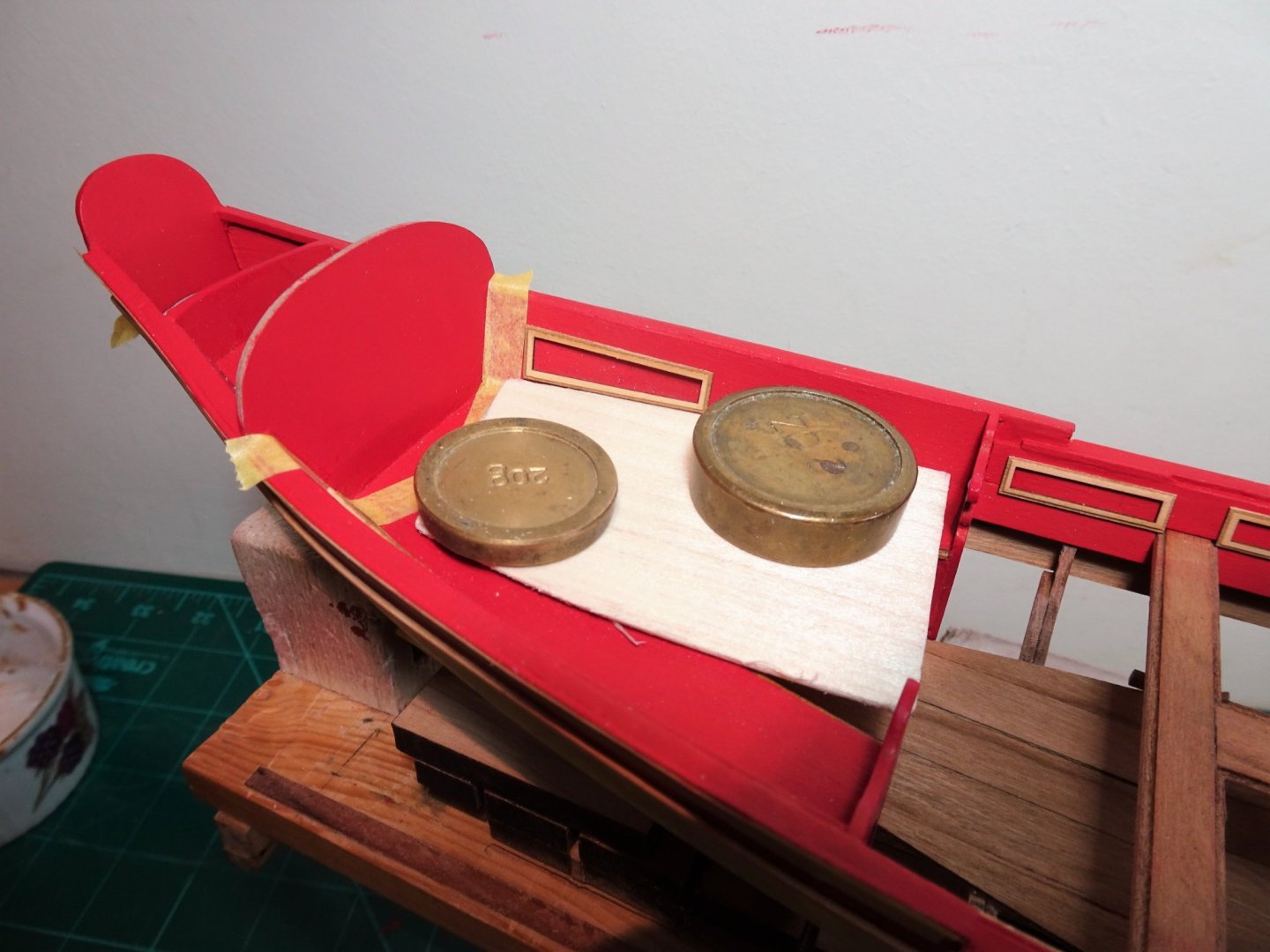
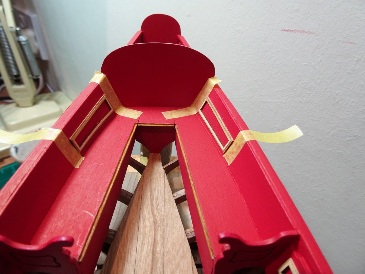
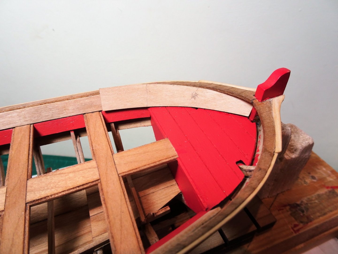
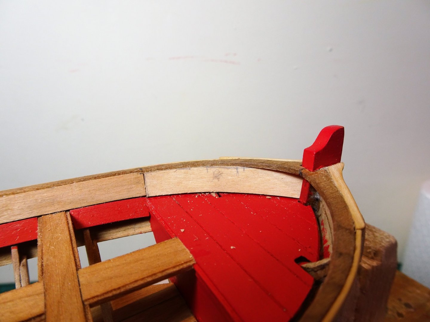
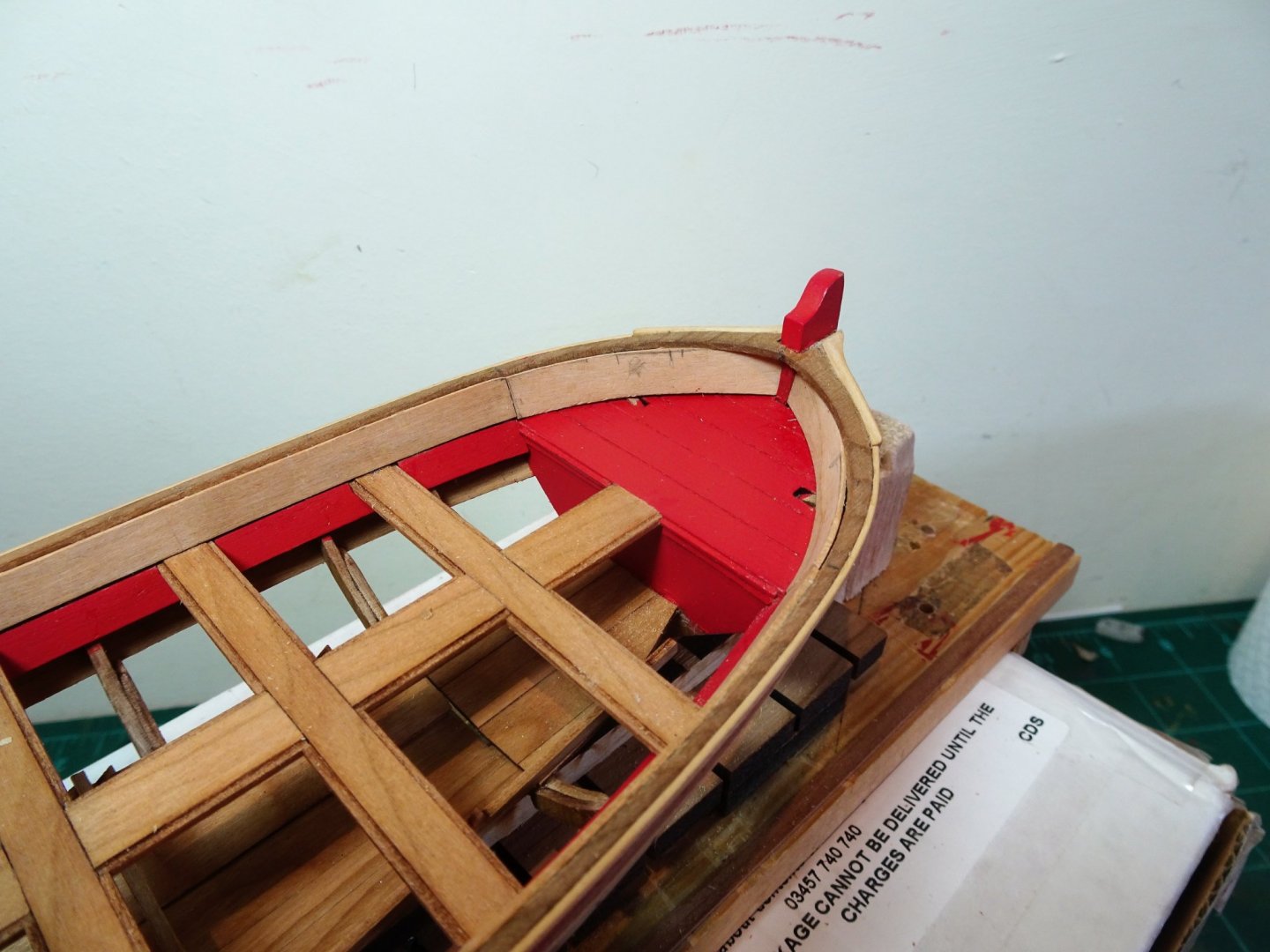
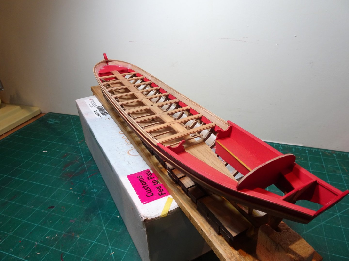
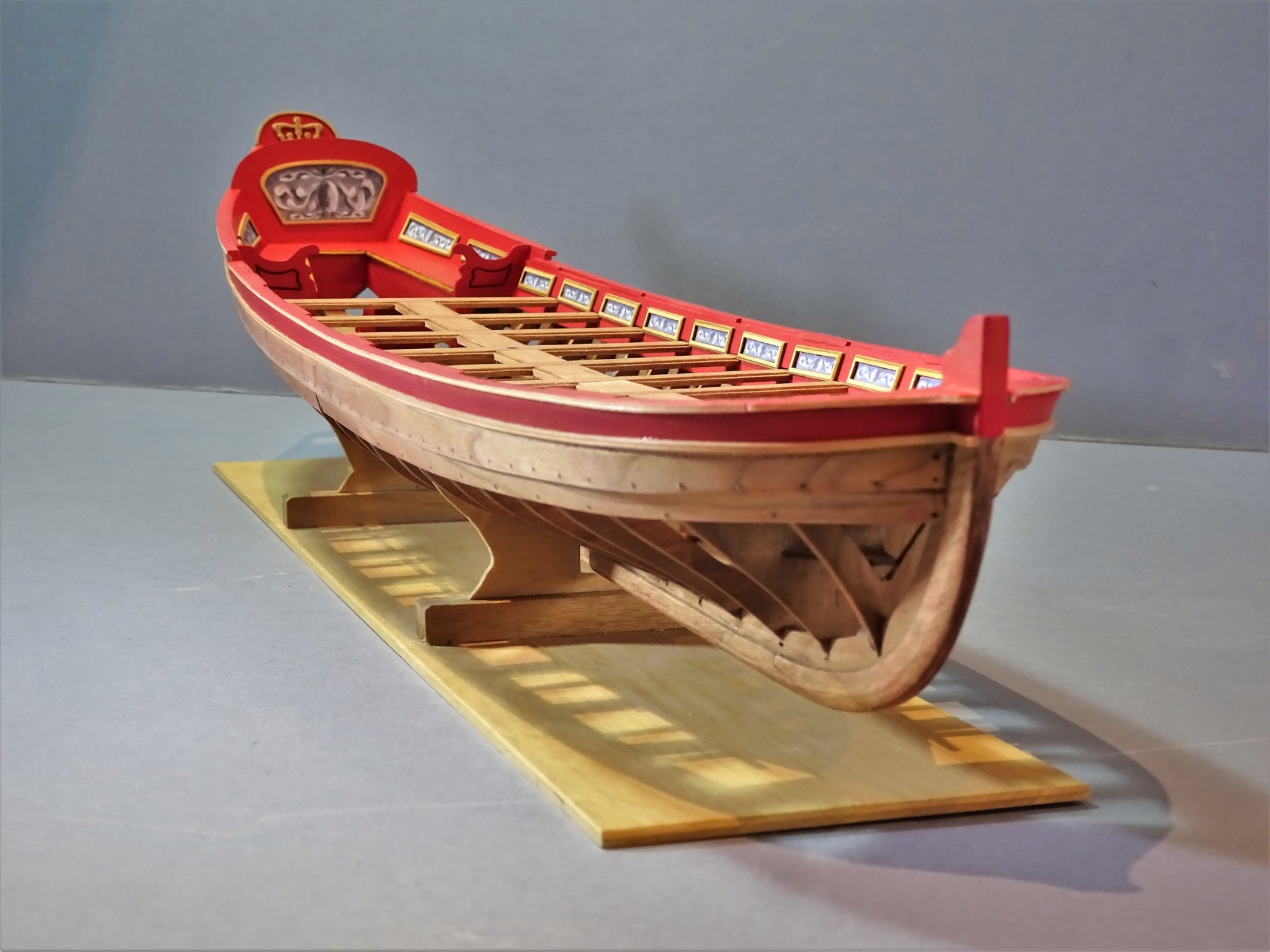
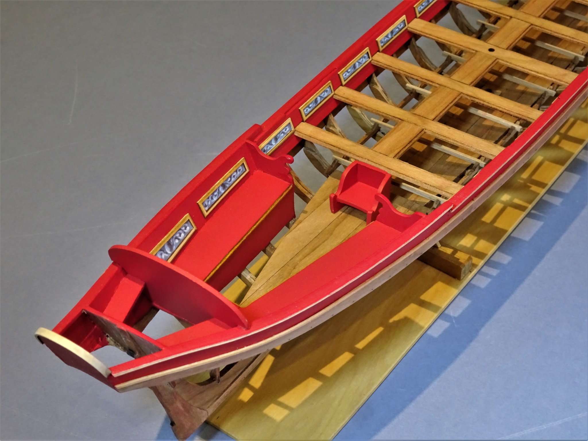
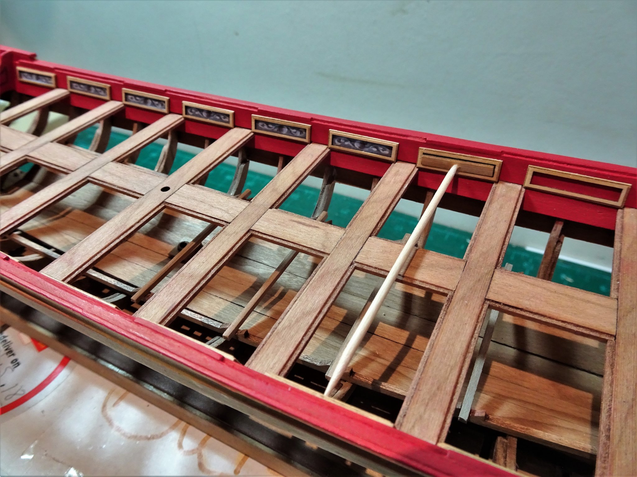
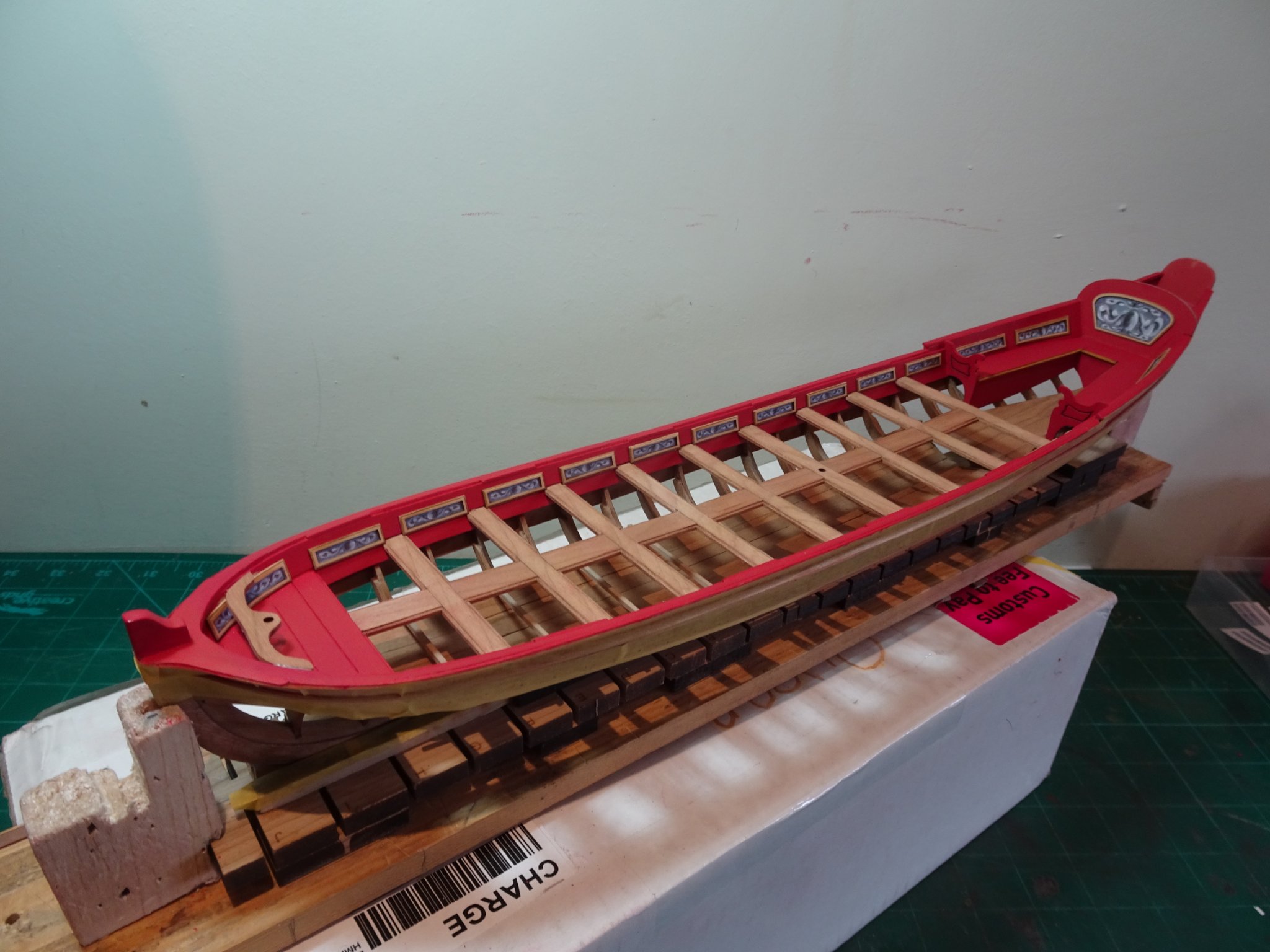
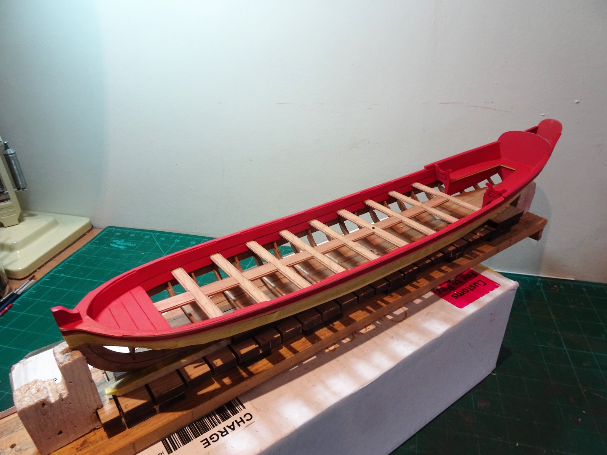
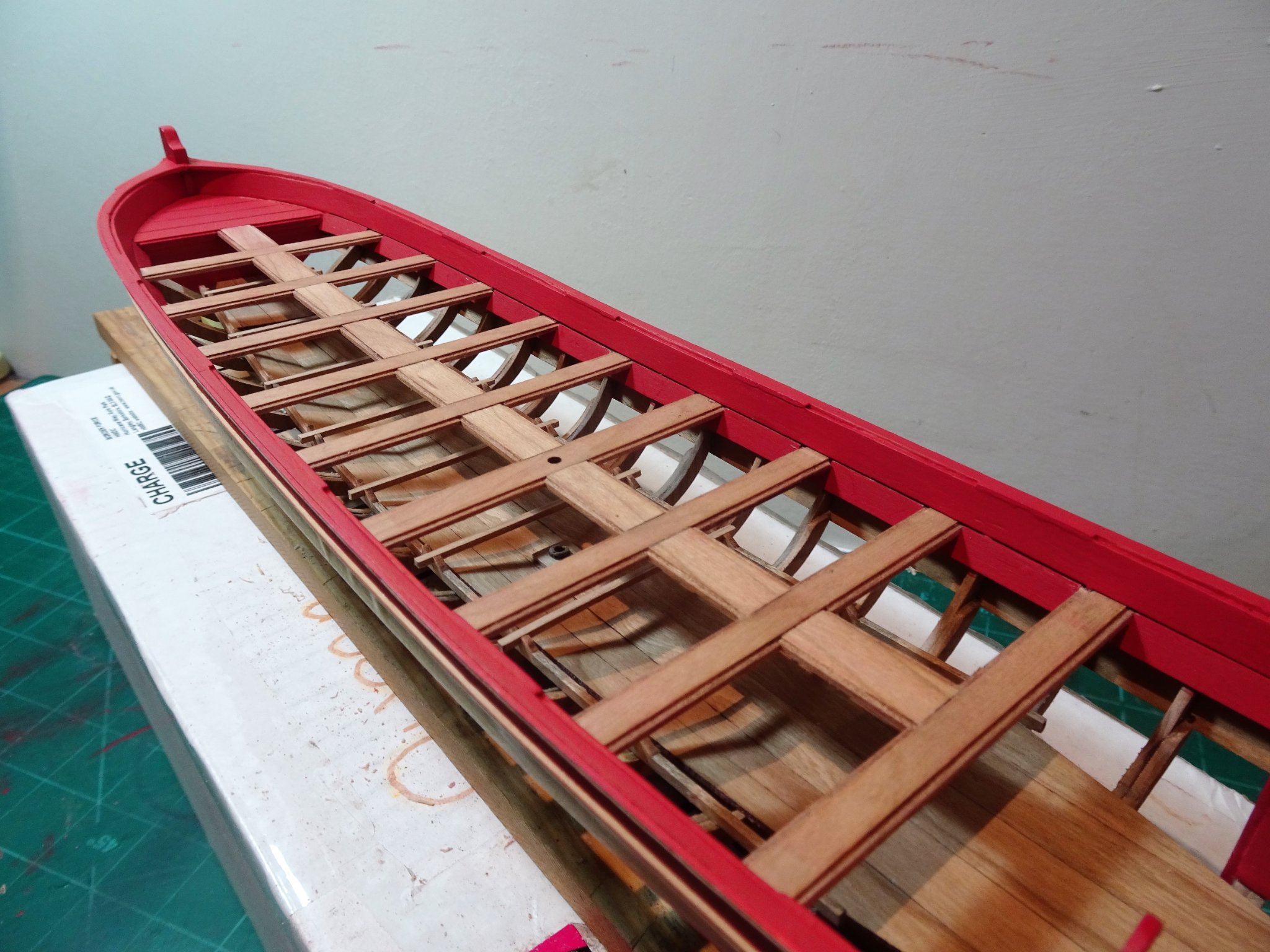
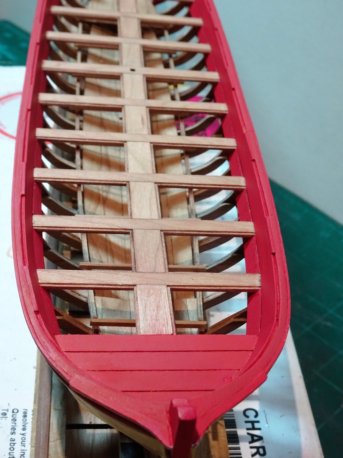
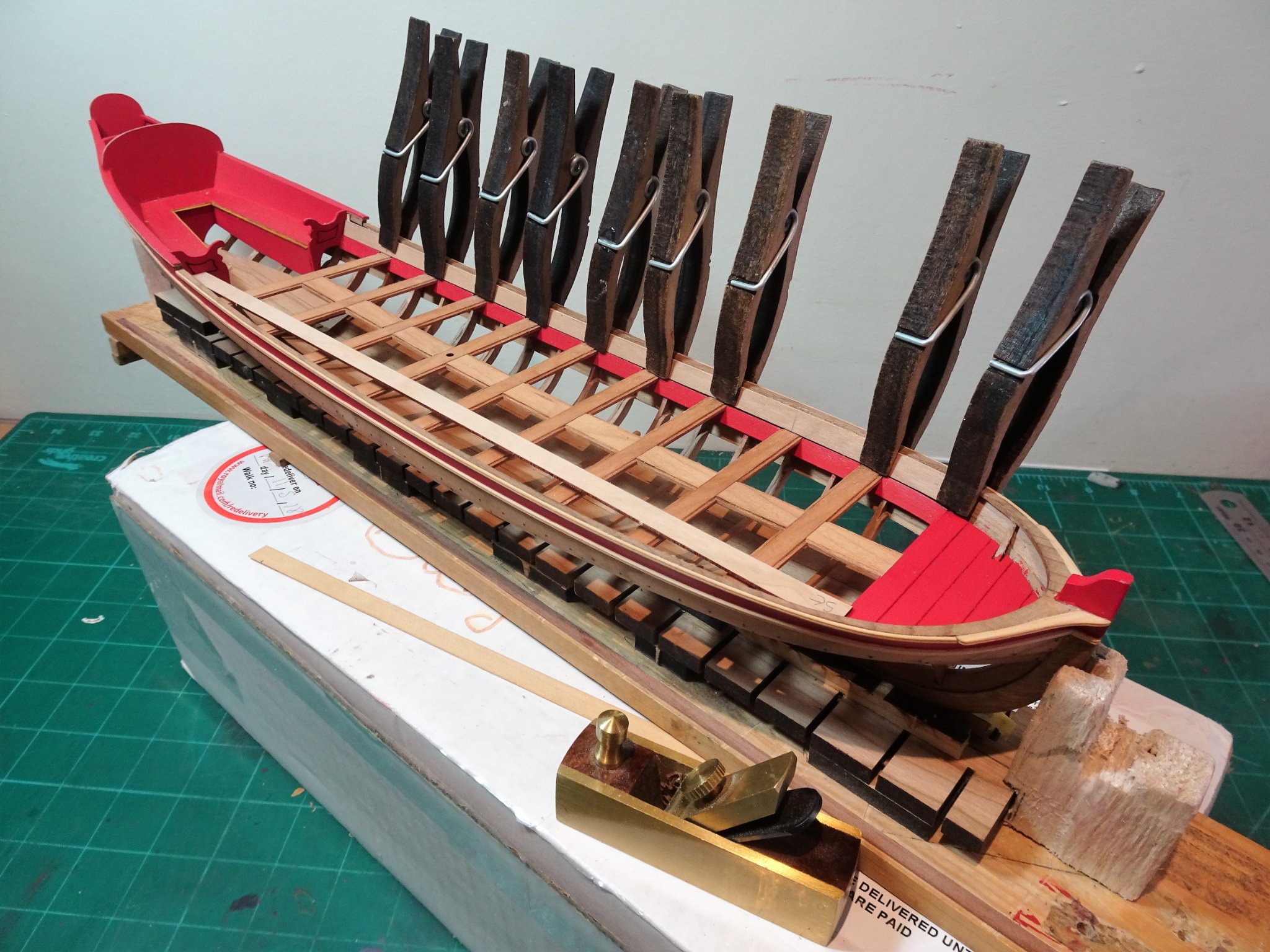
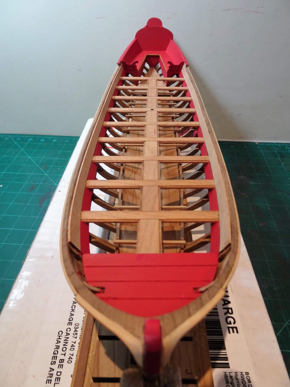
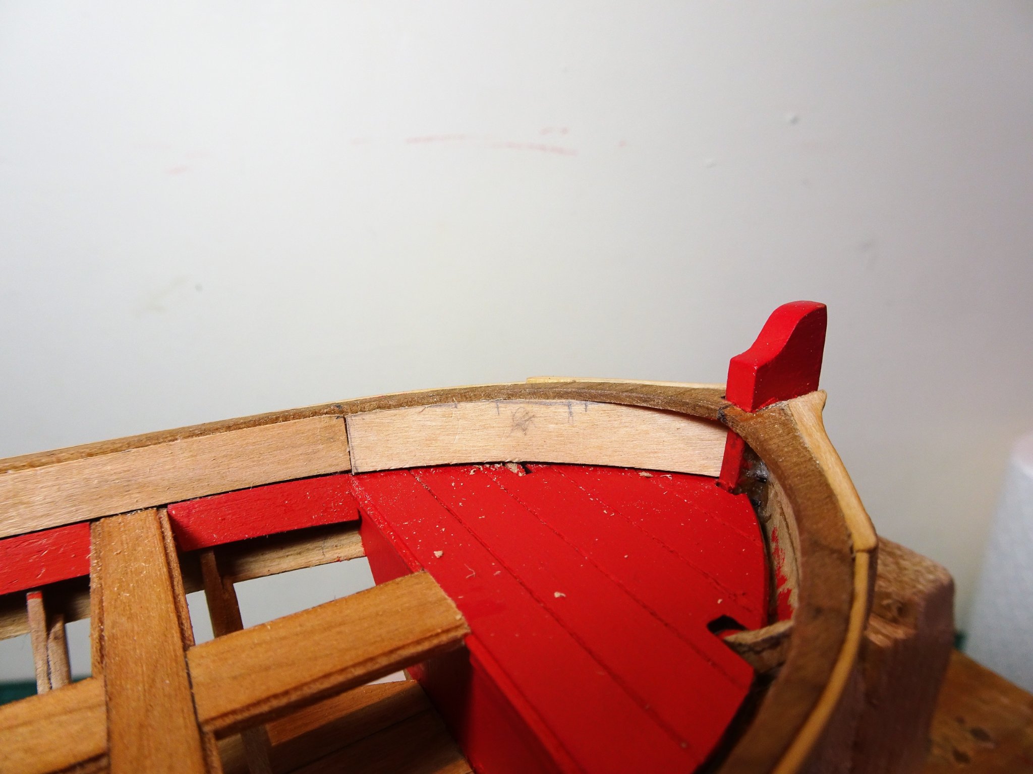
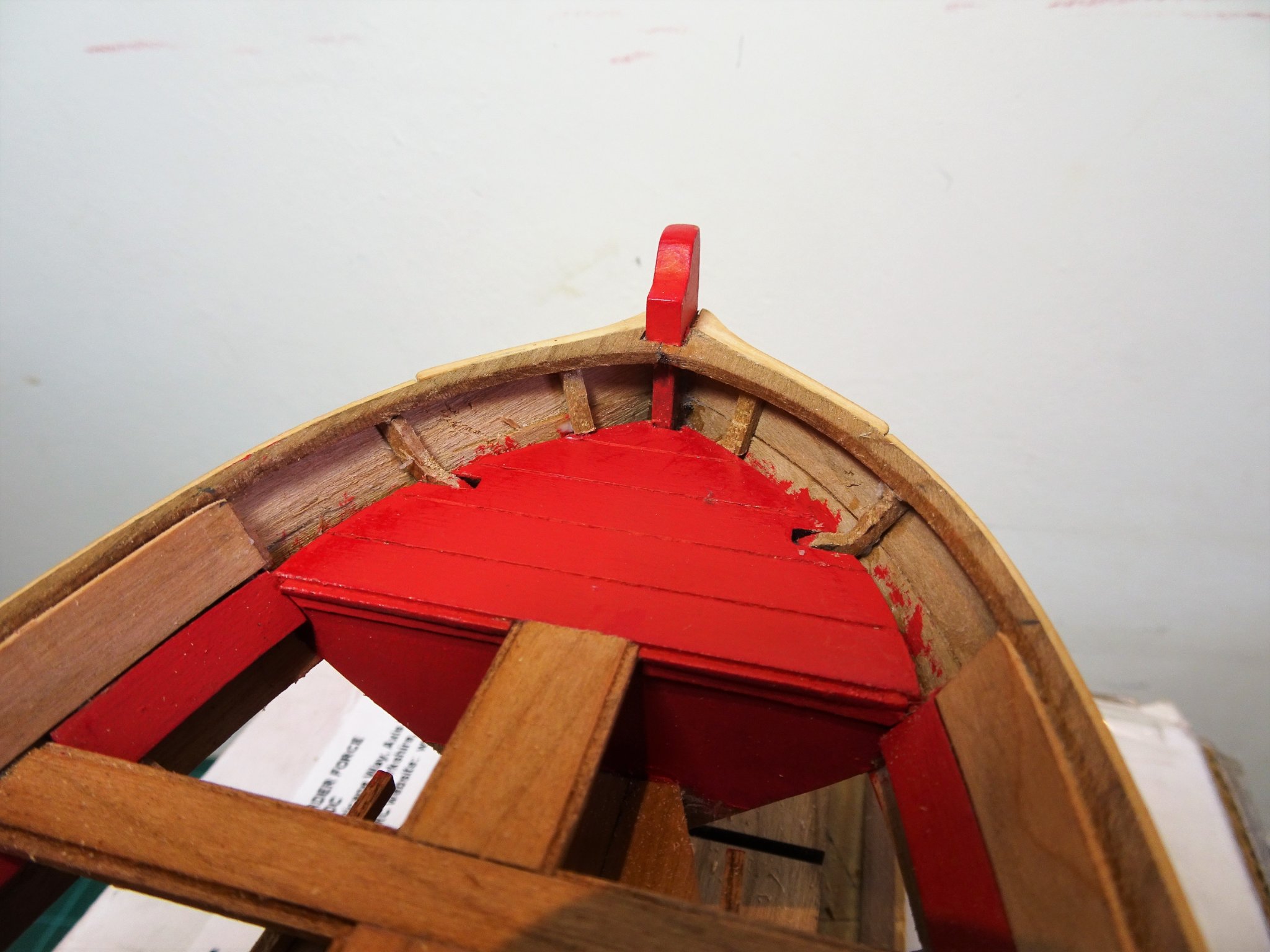
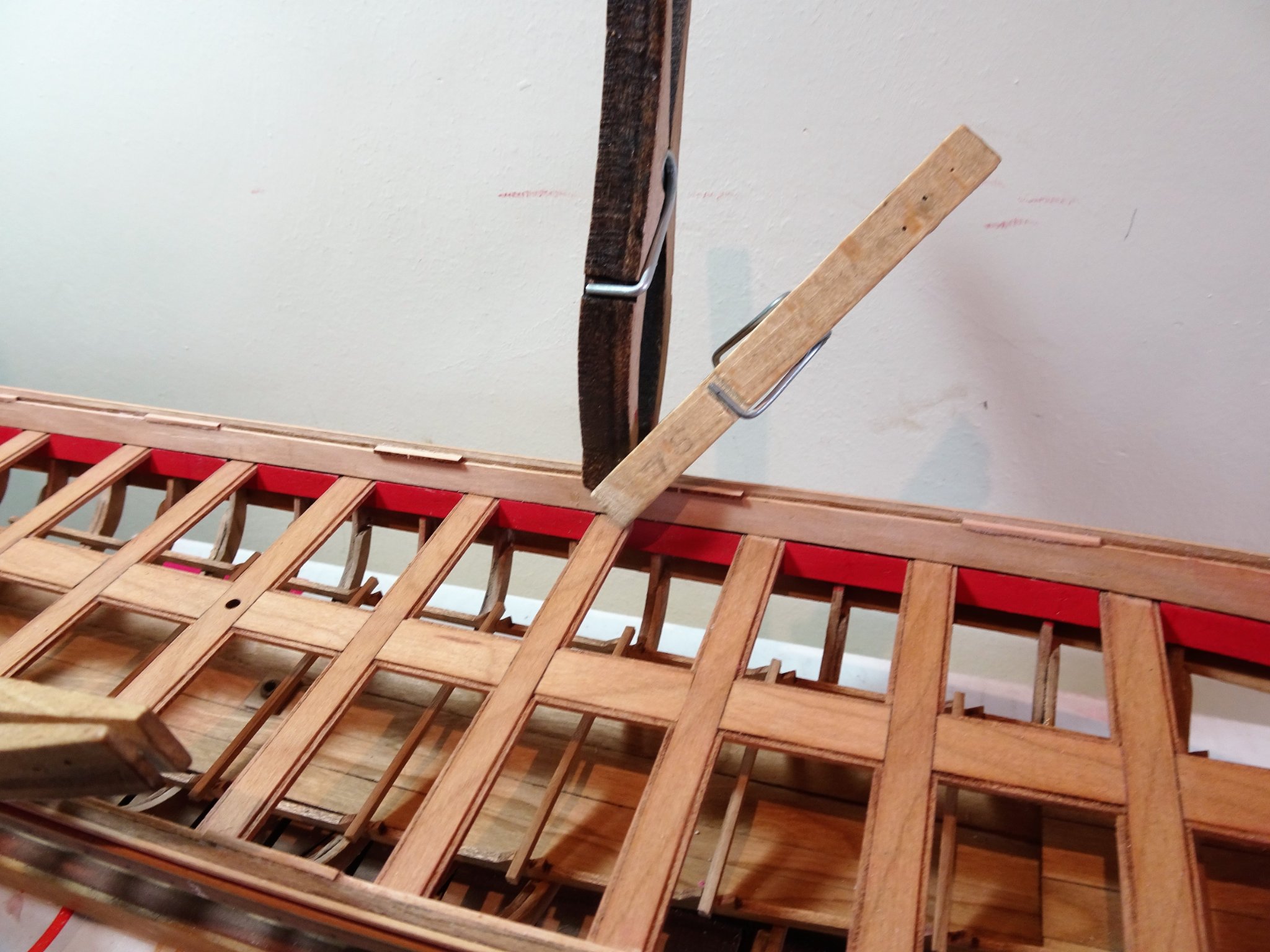
Post Thirty-three Inboard Planking. Spiled Laser cut strips are provided for the purpose, but these still need tweaking to fit properly. The bottom edge sits tight against the riser top and across the thwarts, the top edge is required to run up to the lower edge of the capping rail. In the case of my build the strip simply requires sanding of the top edge to reduce its width a tad. I marked the position of the thwarts on the strip and measured the distance between riser and capping rail using a tick strip method. The marks were transferred to the strip and the sanding line marked. It was then simply down to sanding and test checking. 1966 Once satisfied, the strip was clamped into place and given the hairdryer heat treatment to take the tension out of it before final gluing into place. 1972(2) Note the rabbet formed with the Capping rail. 1971 Both strips fixed into place. The trickier element of the inboard planking is a shorter section that runs forward around the curve of the bow. These are also pre- spiled but will need some fettlin’ to fit. 1976 The first task is to water/heat bend to fit the curve. 1977 The forward end is firstly trimmed to fit beneath the rail. 1987 By degrees the top edge is sanded and the length cut to meet the long strip. 1988 To support the panel I added an additional ‘false’ frame each side beneath the rail. This something Chuck mentions in his pdf Instructions and is worth doing to properly secure the panels. 1993 Sections glued into place. 1995 The final assembly of this part is to add small sections to provide a wider surface for the thole pins to sit. These sections are laser cut, and simply require sanding flush with the capping rail. 2002(2) 1998 A little filling and smoothing and she’s ready to lay some paint down. I suspect there will be several sessions of paint, fill and sand, before she is ready for a final coat. B.E. 23/05/21


.thumb.JPG.be64e0acaae09c3befe13be8aab798e9.JPG)


.thumb.JPG.c2dc0d9e73b4936376f73703059635f8.JPG)
- 185 replies
-
- 15
-
-
- queen anne barge
- Syren Ship Model Company
- (and 1 more)
.JPG.e0c8dca096fd4a4dedc75abf85038d84.JPG)
.JPG.7d8950dd850a987c379cdc71c5701b11.JPG)
.JPG.f236c11aa52f550b0c3d067b69a485ee.JPG)


.JPG.f61e4da4c0f46a4f64b8ffe0dc026e69.JPG)


.JPG.a2315cf0365de4508165f318daea839b.JPG)
.JPG.fe5c5f282f40de2f696df2209a2f02db.JPG)
.JPG.5654028f4b78ac14635fe39a7d6d983a.JPG)
.JPG.88e50adbdb76978fb2669d0dd7a0aa33.JPG)
.JPG.3bfb89122acb386ea67cad67c73a689e.JPG)
.JPG.8fd261a8827776c83e1c30cbecc949d8.JPG)
.JPG.852f939a42ed2066b3289d85a7b978f7.JPG)
.JPG.a41ff5f6acc081b2489379844e1666a4.JPG)


.JPG.0ae62b7107f8b669cd359c94e324bfc6.JPG)

.JPG.4d7aabc7f31155b76ef302b8624ea6cd.JPG)
.JPG.9169274290b64e7326d849a4c89aef26.JPG)


.JPG.71fdd440bb2d63f55d48b6a798741dad.JPG)

.JPG.9be7db995e7d7d82aed90596891f1931.JPG)
.JPG.bdd5bf071d8d61f11ec763f1dd379261.JPG)
.JPG.2a3f83ac5a80778eea9ba1641f860684.JPG)
.JPG.a9d6b8c9595d3292b9cab30983eb4001.JPG)
.JPG.65ab409c0bbf3bb112d6706015dac162.JPG)
.JPG.c7b65defe1c591cc80af01b126419682.JPG)
.JPG.a9bc51d11026969a940f0783c1f515e0.JPG)
.JPG.41fb6d6ca5afdce1114cfb902c3b9628.JPG)
.JPG.073de2622e4096d4a1d940940d3c4639.JPG)
.JPG.4ed2073bdb6fea6230122b31bb6bb1ee.JPG)
.JPG.20cd25d434e34b4134e563380c21f767.JPG)
.JPG.ce7c2030fec6c467e0349aac23e22763.JPG)
.JPG.94c09a252e34fed7bb0c8ece57c68ecb.JPG)
.JPG.daf47ff89f925312f3444970f2ca53c3.JPG)


.JPG.e57d27e2d155a28051db7a9b8d1c4909.JPG)
.JPG.052735c02f0f8a5ea32a4b7043907eef.JPG)
.JPG.dcac4e57475d4974eb1d0c455e51db81.JPG)

.JPG.596675a6f1b44f19bf15020ac4347d17.JPG)
.JPG.92b5a3a0547652d715de11d051fb2f21.JPG)
.JPG.fb7e436a9f452b2759c81a05e7e8b344.JPG)
.JPG.89396bb34327855d7bd3b486ec0e5f4b.JPG)


.JPG.b30ed6cefc273d92fd43fb5e2d8db260.JPG)