HOLIDAY DONATION DRIVE - SUPPORT MSW - DO YOUR PART TO KEEP THIS GREAT FORUM GOING! (Only 13 donations so far - C'mon guys!)
×

Moonbug
-
Posts
1,028 -
Joined
-
Last visited
Content Type
Profiles
Forums
Gallery
Events
Everything posted by Moonbug
-
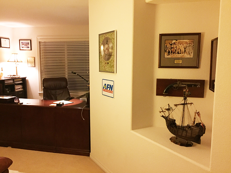
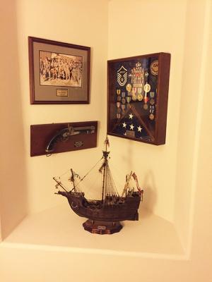
 Thanks very much gents! Indeed marktime. A tragedy in many ways. In the meantime - here's her temporary home in my office until after the new year, when the Admiral will allow her to be moved a place of more prominence. - Bug
- 274 replies
-
- 13
-

-
- Santa Maria
- Artesania Latina
- (and 2 more)
-
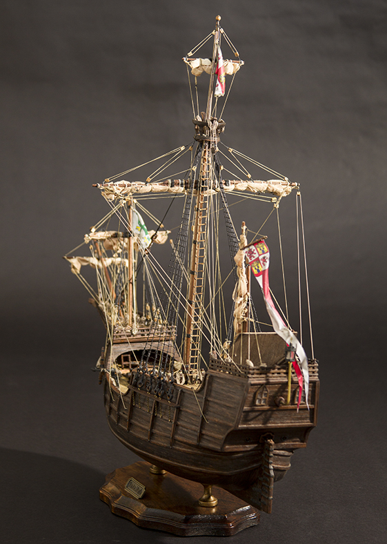
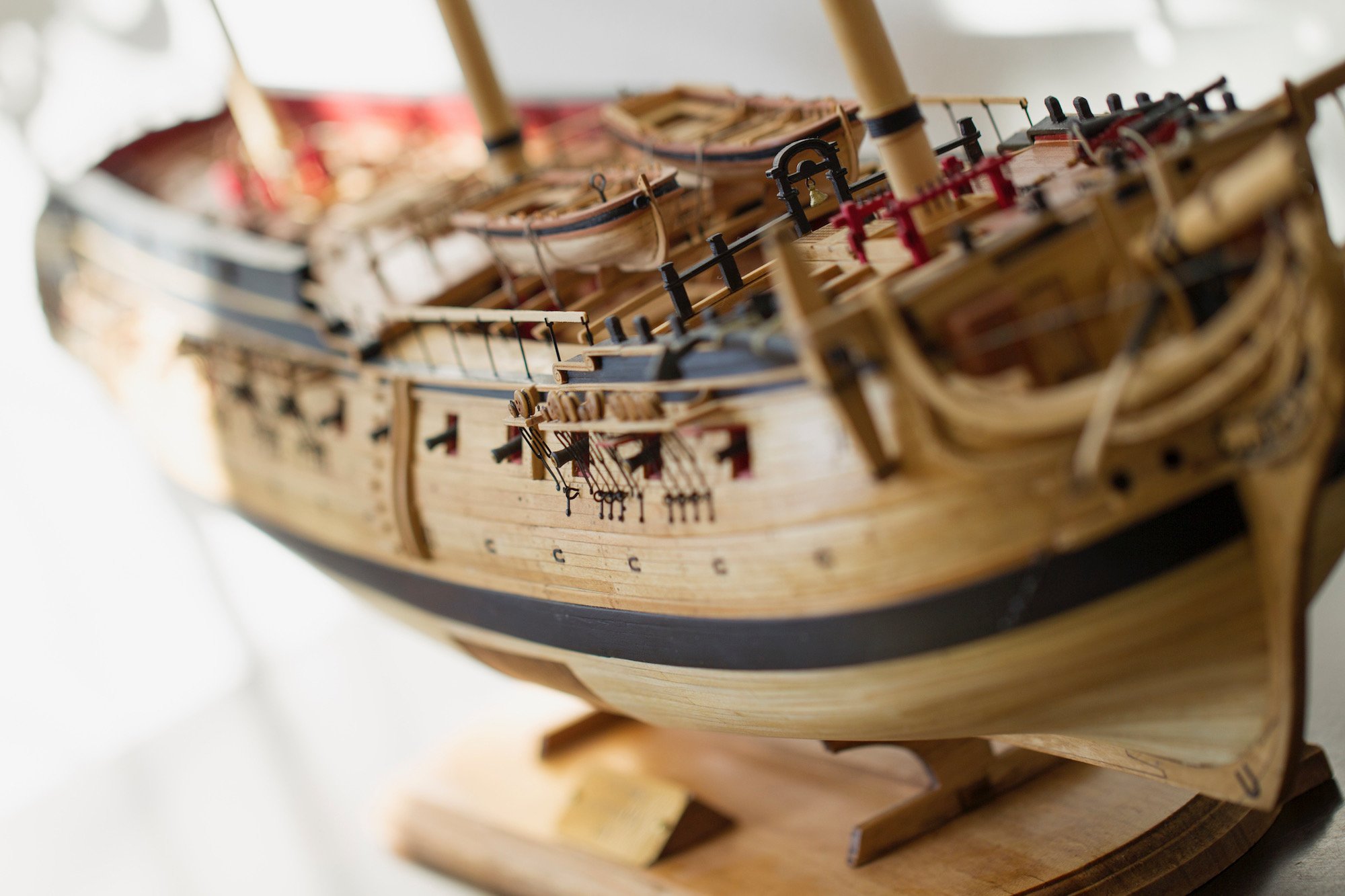
And a few more. I'll gather them and add to the completed gallery in a bit. - Bug


- 274 replies
-
- 20
-
-
- Santa Maria
- Artesania Latina
- (and 2 more)
-
Thanks Ian! I am indeed, turned out pretty well. Always a bit of mixed feelings when you finish a project. - Bug
- 274 replies
-
- 2
-
-
- Santa Maria
- Artesania Latina
- (and 2 more)
-
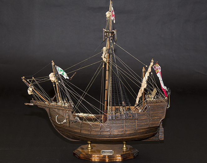
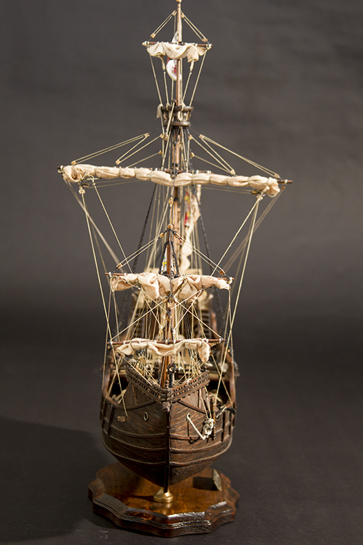
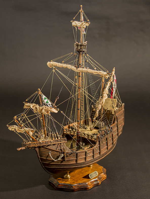
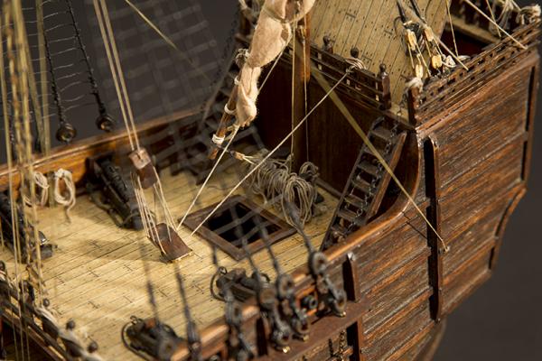
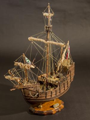
Well folks... looks like she's done. Here she is - the completed Santa Maria. I'll edit and post more of the finished photos, then eventually her final port of call - I have to wait for the Admiral to clear off the Christmas decorations after the new year before the Santa Maria can rest in her final spot. Thanks for all the likes and comments!
- 274 replies
-
- 17
-
-
- Santa Maria
- Artesania Latina
- (and 2 more)
-
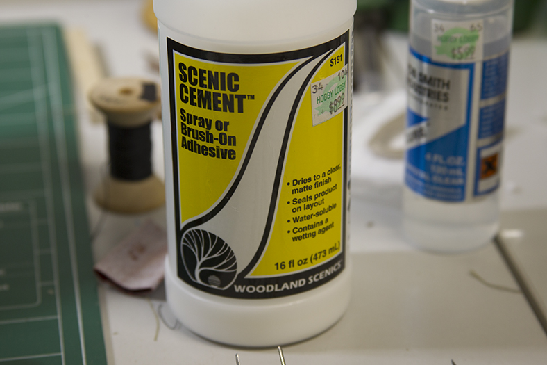
Thanks Ken! Just for clarity in case anyone wants to try it, the glue is hobby scenic glue typically used as a spray before placing shrubbery or other pieces for train sets or diaramas - which is why it's so watered down. -Bug
- 274 replies
-
- 2
-
-
- Santa Maria
- Artesania Latina
- (and 2 more)
-
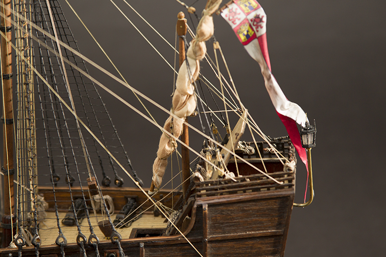
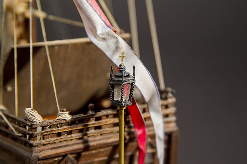
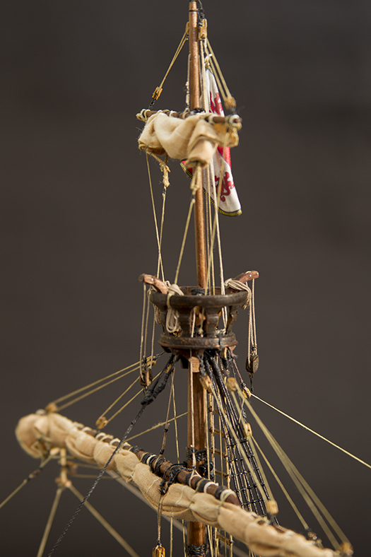
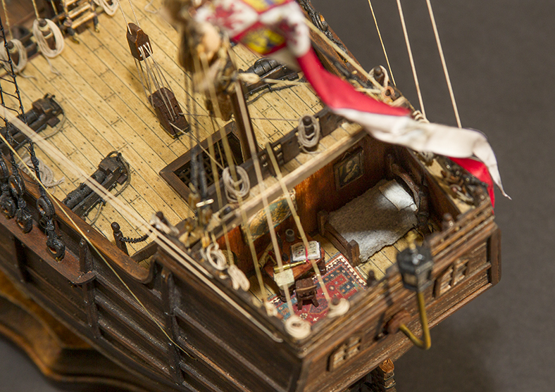
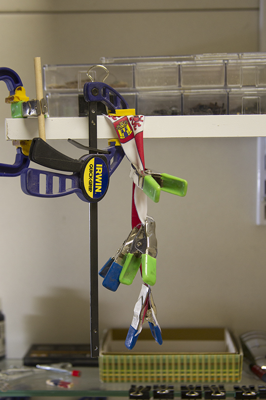
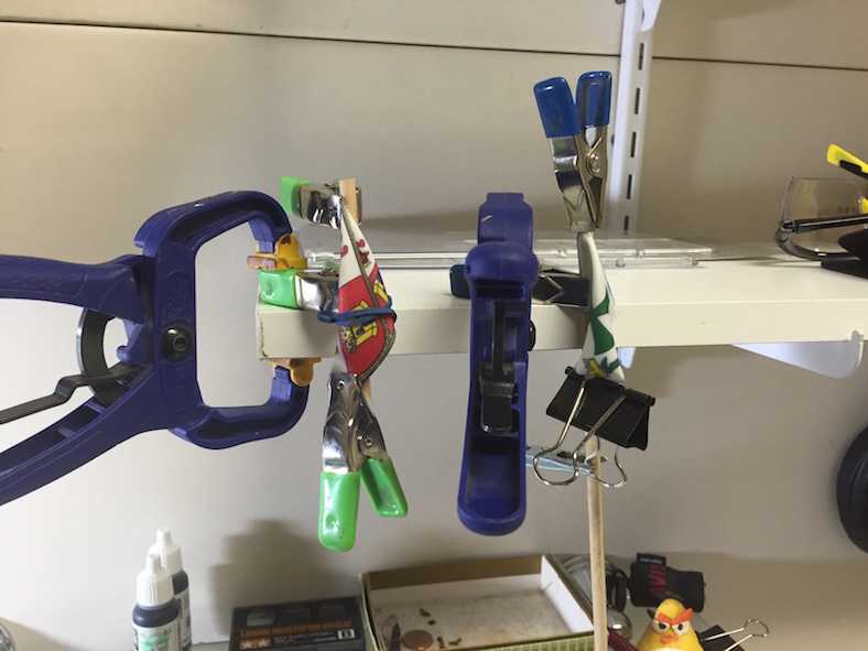
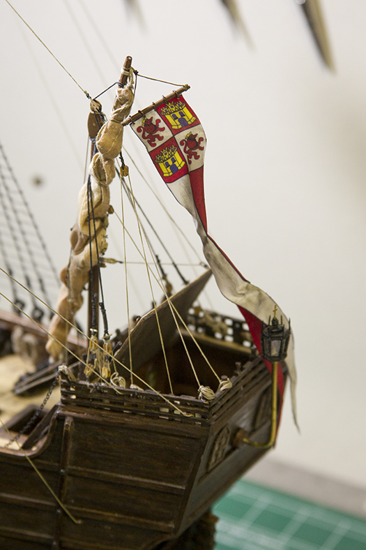
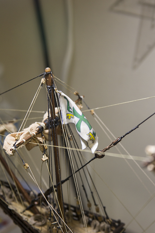
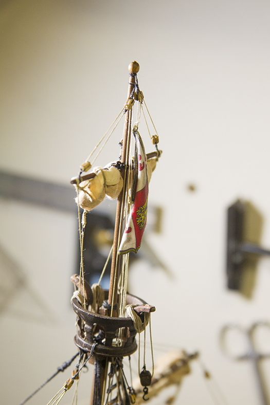
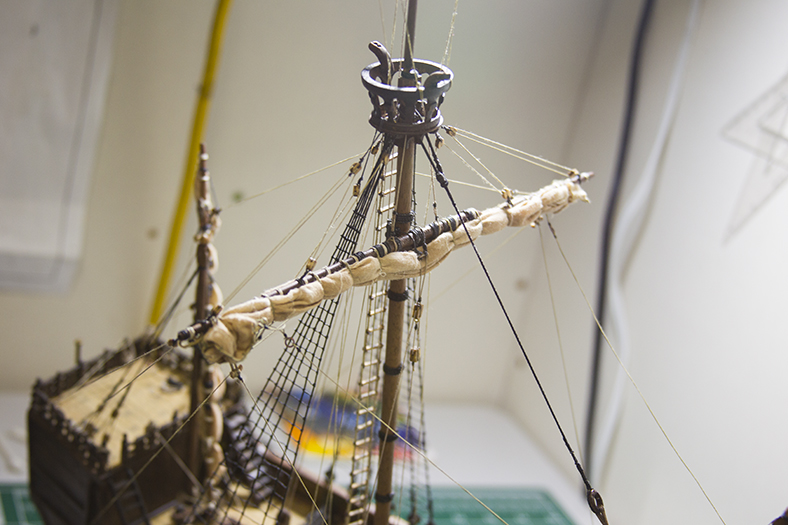
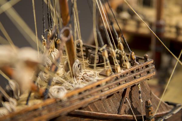
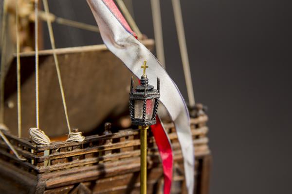
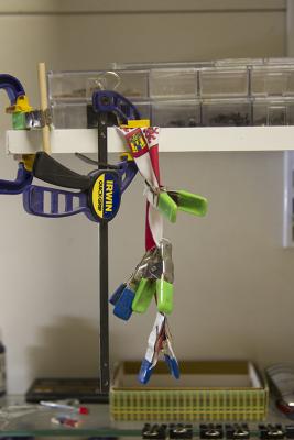
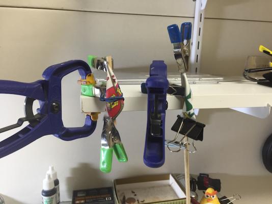
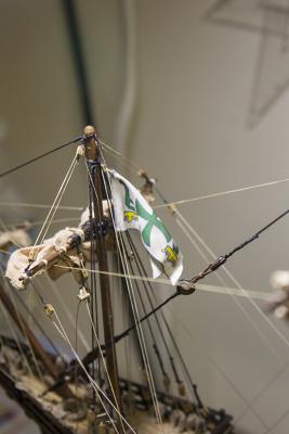
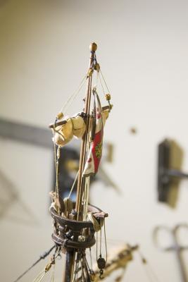
So, as I continue with many of the finishing details, I've been fretting how I'm going to handle the flags. As the sails are furled, I need to give the impression that the flags are hanging somewhat naturally. They also need to have some of the aging that the rest of the ship represents. After scouring my local fabric store, and trying a variety of different silks and satins - I ended up going back to the "flags" that are supplied in the AL kit. First, I soaked the flags in the same 'Scenic glue' that I was using for the rope coils. Then I hung the flags from my shelf, and shaped them with a variety of clips and gravity. To give them the shape I wanted that would imply hanging naturally. I then mounted each of the flags. The main and fore mast flags using blocks, and the mizzen using a mounting as illustrated in Pastor's book. I then aged them using some black and brown dusting. Overall, I'm pretty pleased with the outcome.

- 274 replies
-
- 17
-
-
- Santa Maria
- Artesania Latina
- (and 2 more)
-
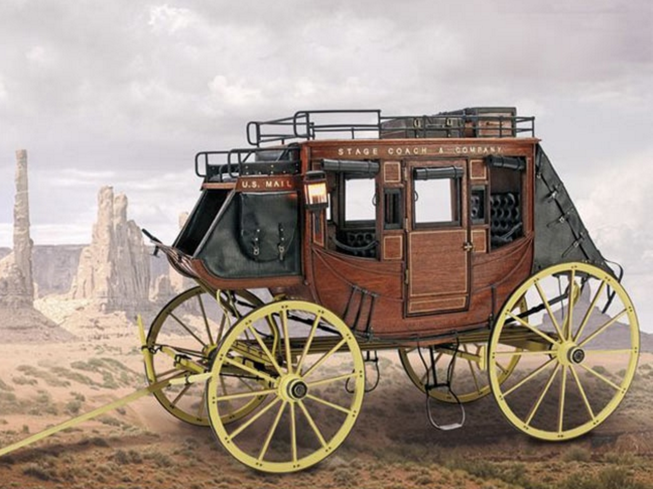
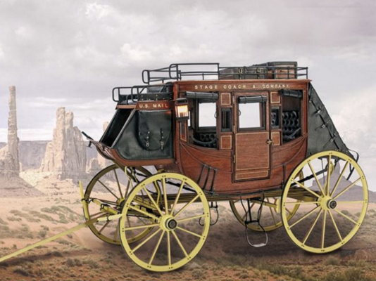
Fantastic Nils! I am almost positive the Pegasus is going to be my next build - following a brief hiatus to build the Artesania Latina Stage Coach. And I guarantee your build will be close on tap for reference! - Bug
-
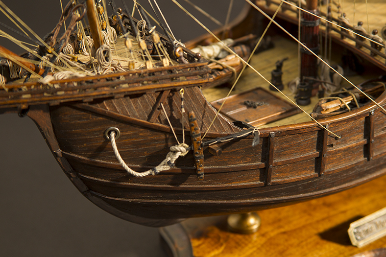
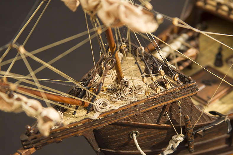
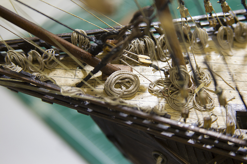
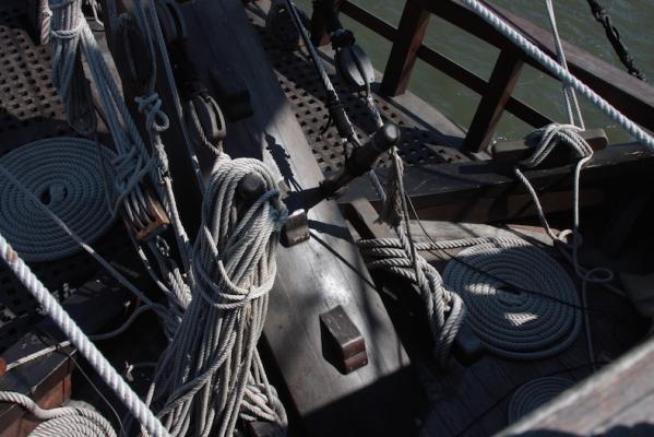
Thanks marktime and Frank! I appreciate the comments. Marktime - I remember those photos, I can't for the life of me find them again. Although that '92 replica was pretty far off in terms of accuracy (I think it was even a caravel instead of a nao), it had some great details to look at, for sure. I got that same vibe you're speaking of when I visited the El Galleon in St. Augustine, Florida last year. That said - I'm attributing the more chaotic look to my rope coils as a result of the crew dipping into the rum a little heavier than normal just as they pulled into port for a very long anticipated shore leave...
- 274 replies
-
- 5
-
-
- Santa Maria
- Artesania Latina
- (and 2 more)
-
Very cool idea, and nice execution. Well done Denis! - Bug
-
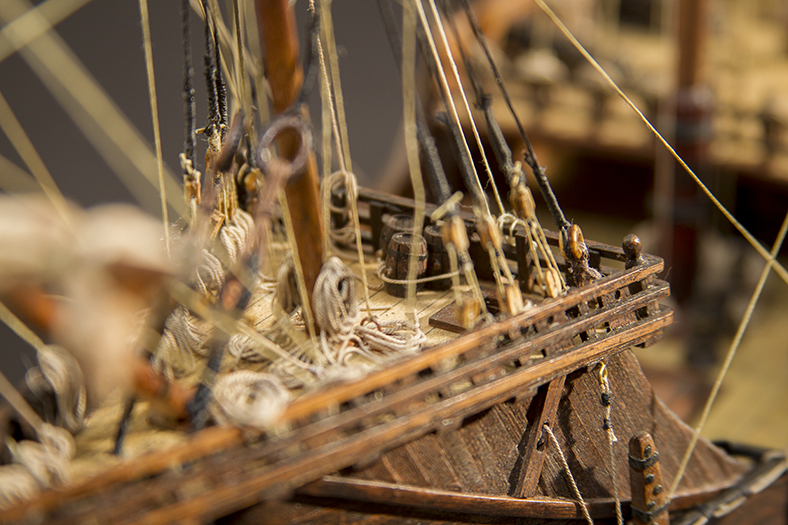
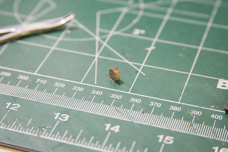
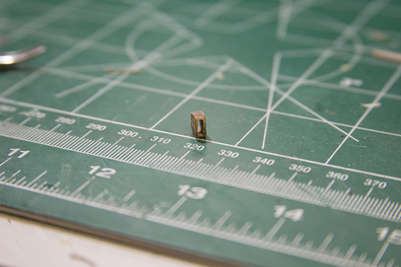
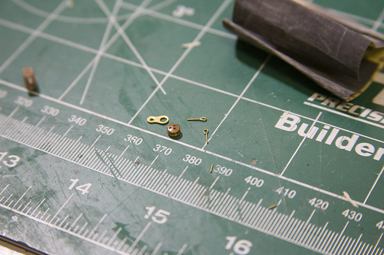
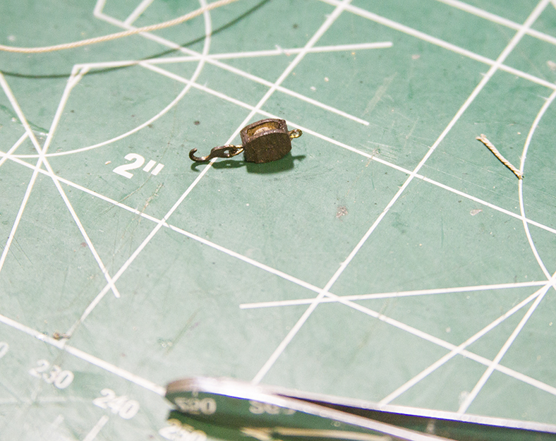
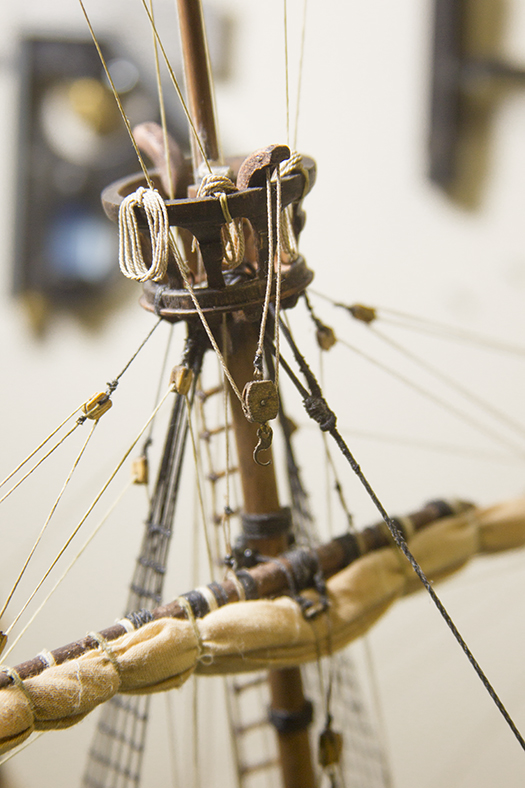
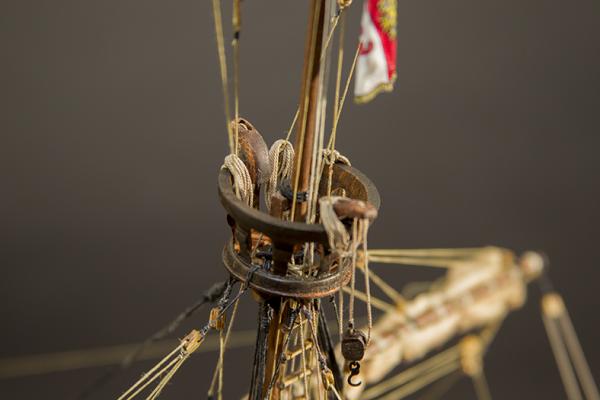
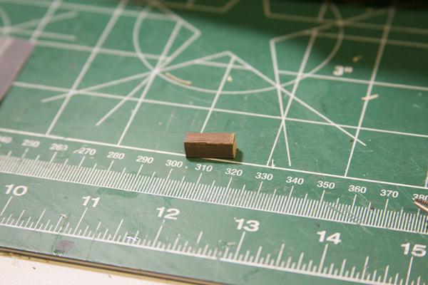
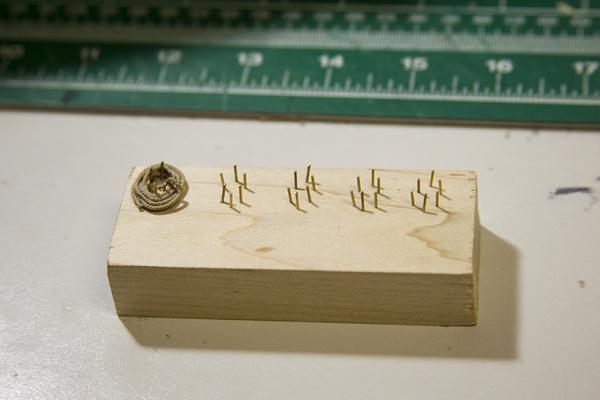
I'm at the stage where I'm working on details at this point, of course. So, along with coiling endless amounts of rope, I needed to create a pulley for the Crow's nest sheaves. I started with a square 5x5 piece of scrap and cut off about 3mm of it. I rounded the edges then drilled out the center. Then, I decided instead of cutting my own sheave to slide in, i could sand down the sides of a scrap deadeye instead. The tiny pins are scrap leftovers, and the other metal piece is a leftover scrap piece that AL loves to use for attaching shrouds. I don't use them, so I have a bunch of them lying around. That will eventually become the 'hook'. Finally, I assembled it all together and darkened the metal and wood. I then attached it to the ship and coiled the rope.


- 274 replies
-
- 7
-
-
- Santa Maria
- Artesania Latina
- (and 2 more)
-
Hey Chris, When I did the coils of the San Juan I glued them to a standard piece of computer paper, then peeled them off. I also just made a post about my rope coils for the Santa Maria. http://modelshipworld.com/index.php/topic/4923-santa-maria-by-moonbug-artesania-latina-bashed/page-12 -Bug
-
Beautiful stuff mark! That's really, really nice looking work. Something to envy for sure for those of us who struggle mightily with hull planking. And of course - particularly given my recent post regarding furling or unfurling the Santa Maria's main sail - I'm predisposed toward agreeing with the Admiral. :-) - Bug
-
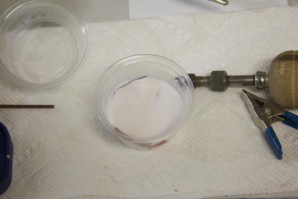
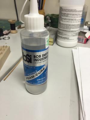
Here's a better picture of the styrofoam glue.
- 274 replies
-
- 4
-
-
- Santa Maria
- Artesania Latina
- (and 2 more)
-
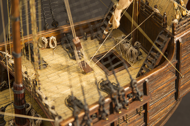
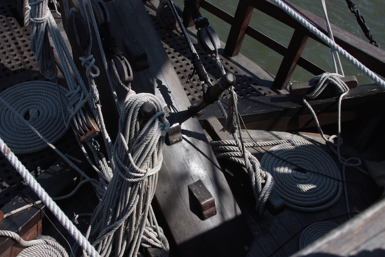
Good morning, Not a lot of photos to show just yet, but I've delved into the tedious job of coiling and tying off rope. I started out by building a jig, and going with that particular method - but it's only useful in a couple of places where the coils are essentially sitting on their own, or hanging off a cleat or rail. For most of the rope, that's attached to the end of a rigging line, I'm actually coiling by hand for each spot, so that it wraps around the end of the rigging properly and looks more natural. I am primarily using two types of glue. The Scenic glue that I mentioned before dries very clear and clean. As I said - it's NOT very tacky, so the coils need to be in place and how you want them laid out, then the glue is applied with a Q-tip, or sometimes small brush. The glue behind it - sorry it's kinda blurry - is actually a styrofoam glue that I came across at my local hobby store. It's VERY tacky - much like a rubber cement - so it's a bit messy, and quite honestly a pain in the butt. HOWEVER, it's also very effective if you brush it on the back of a coil because it allows you to immediately shape the coil and place it where you want it. It holds very nicely, but then takes several minutes to dry giving you plenty of flexibility to make changes. Once again, I'm growing more enamored with the somewhat haphazard way the rope coils are looking.


- 274 replies
-
- 13
-
-
- Santa Maria
- Artesania Latina
- (and 2 more)
-
Thanks gents! And thanks for the comments Frank - really appreciate it. That's what I love about MSW - so many great, unique builds, it's pretty easy to get lost for a while. And always a good call to go with the Admiralty. ;-) - Bug
- 274 replies
-
- 3
-
-
- Santa Maria
- Artesania Latina
- (and 2 more)
-
Just catching up - what a beautiful build Frank. Absolutely love the naming on the stern! - Bug
-
Ha Nils! I'm confusing a Pickle with a Pegasus! Nice work Peter! *laff* - Bug
- 293 replies
-
- 1
-
-
- pickle
- caldercraft
- (and 1 more)
-
Hey Nils, Been a while since I stopped in on the Pickle. That's my mistake - I'm going to have to stop by more often. Nicely done! Great idea with the hoops. - Bug
- 293 replies
-
- 1
-
-
- pickle
- caldercraft
- (and 1 more)
-
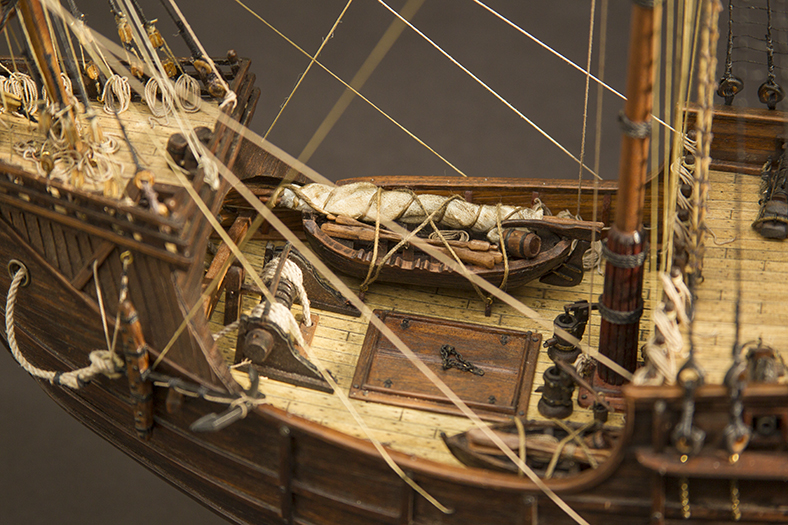
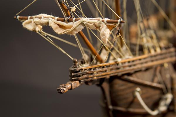
Hey Joe, thanks for the response. I can't argue with logic - so that was my task this weekend. I unfurled the sail, and took another look. Now, if I was going to go with unfurled, I'd also want to detach and re-sew the sail along with bonnets. I also considered whether or not I'd want to add one of the symbolic crosses on the sail as well. Turns out - I didn't really have to go to far to realize that I really liked the sails both ways. So, I did what any normal, red blooded man would do - I asked the Admiral. She liked the sail furled, and since I already have a couple around the house with sails down, she convinced me to go with the "just pulled into the bay" look. :-) The good news is - the entire exercise gave me the opportunity to re-furl the sail and little differently. This time, I wrapped the sail a bit differently, and the sheets and clews are a little further out on the yard. I am much happier with this look, and I think it's ultimately more accurate.

- 274 replies
-
- 14
-
-
- Santa Maria
- Artesania Latina
- (and 2 more)
-
Nice! Great to see you back at it Sjors! Well done! - Bug
- 1,616 replies
-
- 4
-
-
- caldercraft
- agamemnon
- (and 1 more)