Louie da fly
-
Posts
7,993 -
Joined
-
Last visited
Content Type
Profiles
Forums
Gallery
Events
Everything posted by Louie da fly
-
 Sounds like a plan, Arjan. My original question on that thread was because Renaissance galleys all seemed to have long straight sides, so all the oars would hit the water at the same distance from the side of the ship, whereas the dromon had a hull shape more like a longship, narrowing toward the ends. As Cap'n Atli had experience actually rowing a longship, I thought he, if anyone, would know whether oar length in a ship of that shape was a problem. As it turned out, it apparently isn't. Steven PS: Your model looks very elegant.
 -
You might be interested in this discussion regarding the relative length of oars in oar-driven ships - http://forums.armourarchive.org/phpBB3/viewtopic.php?f=16&t=179436&p=2733651&hilit=longship+oar+length#p2733651 I found the statement about inability to keep different length oars in synch enlightening - particularly as I've made the length of oars different for the upper and lower banks for my dromon. I wish I'd noticed this before . . . (I post as Egfroth on the Armour Archive) Steven
- 23 replies
-
- 1
-

-
- oseberg
- billing boats
- (and 2 more)
-
"Too small - throw him back!"
-
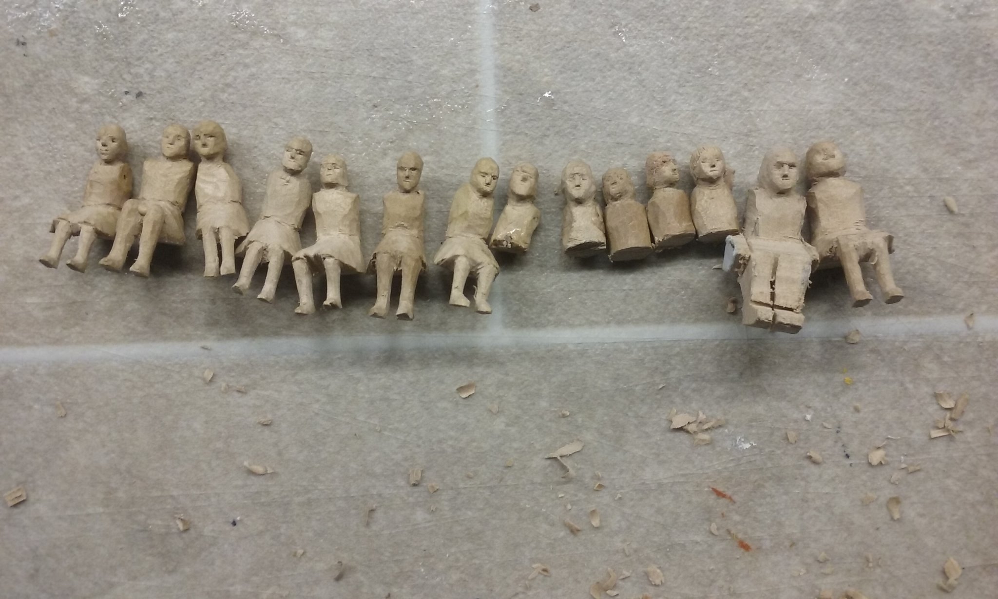
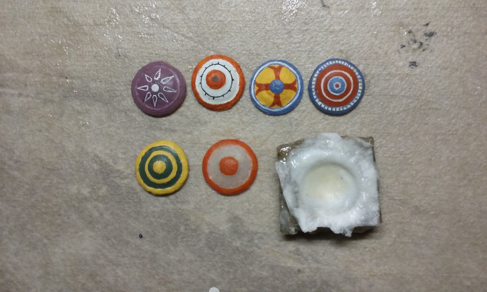
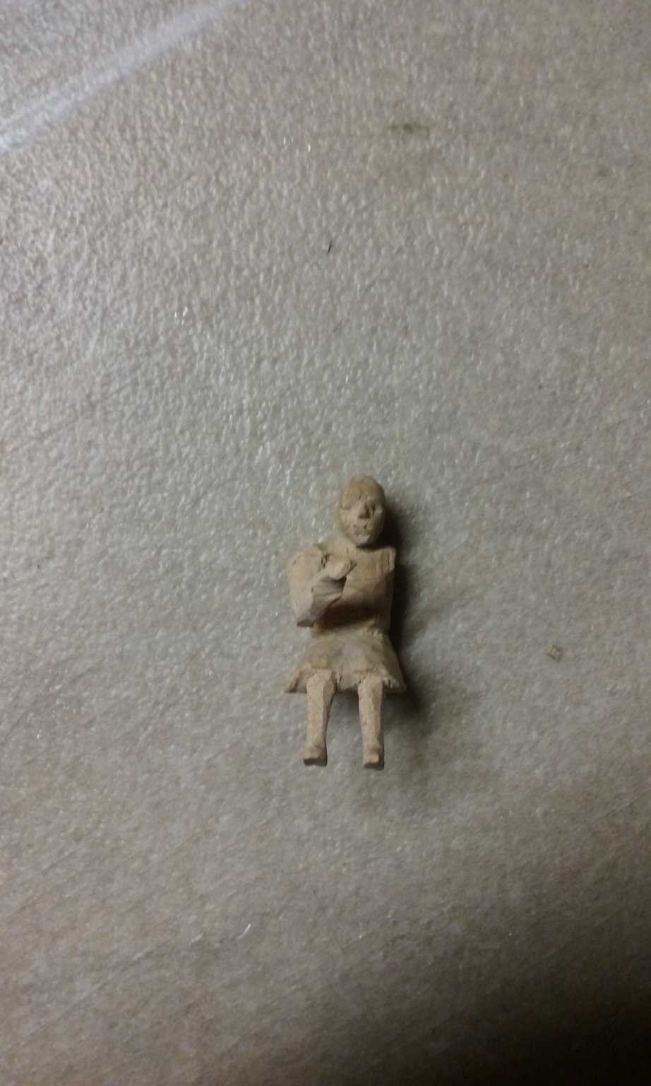
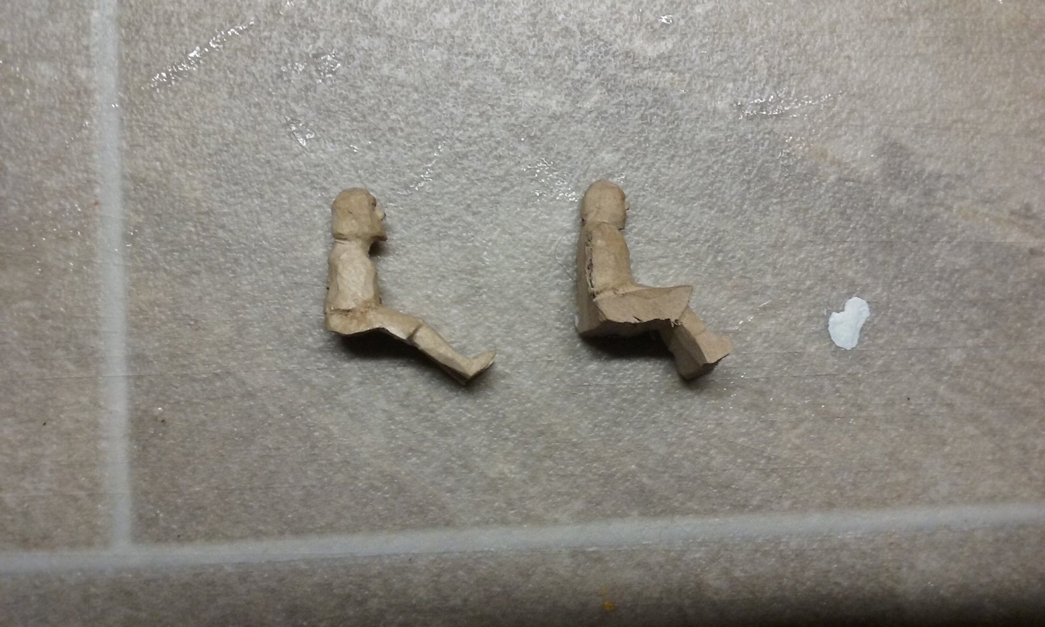
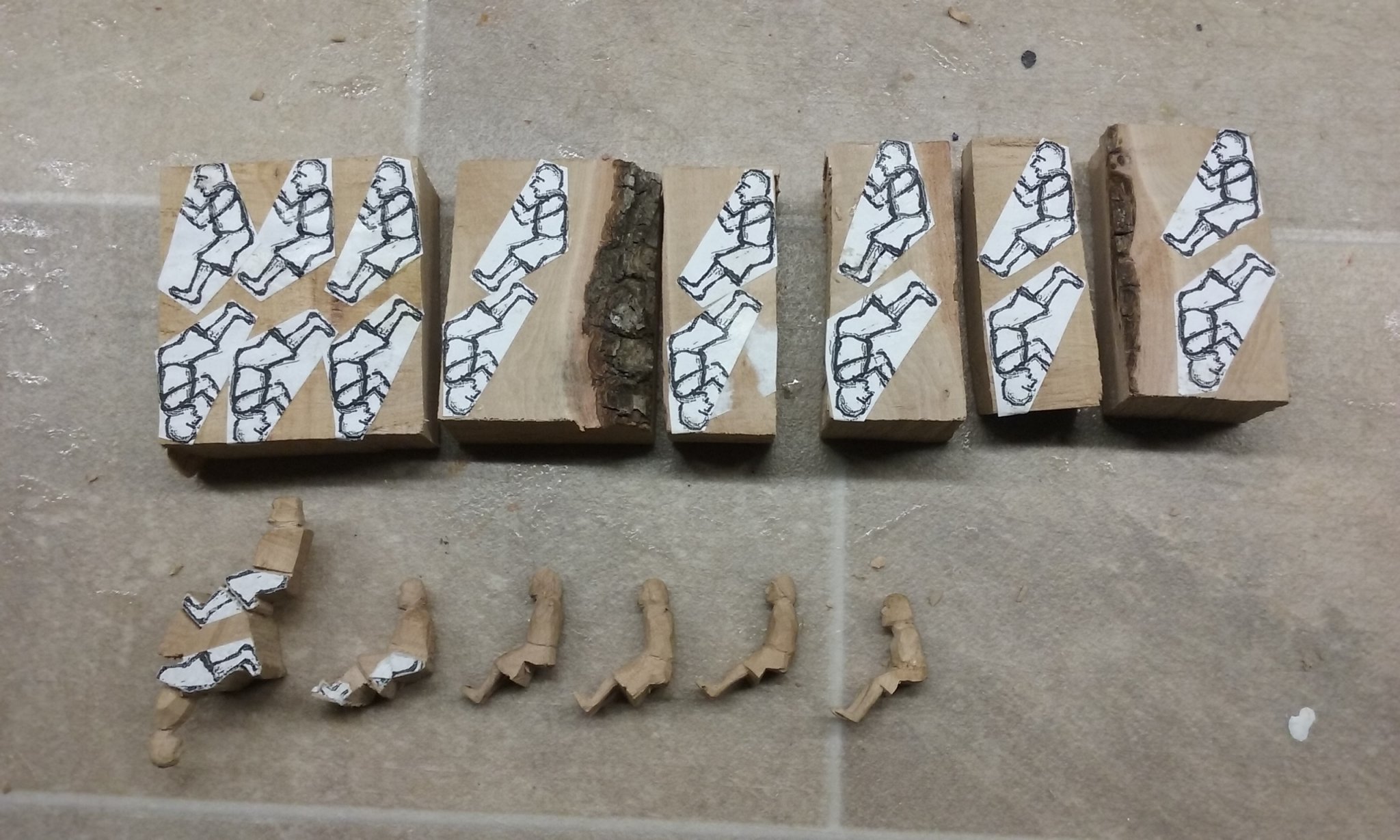
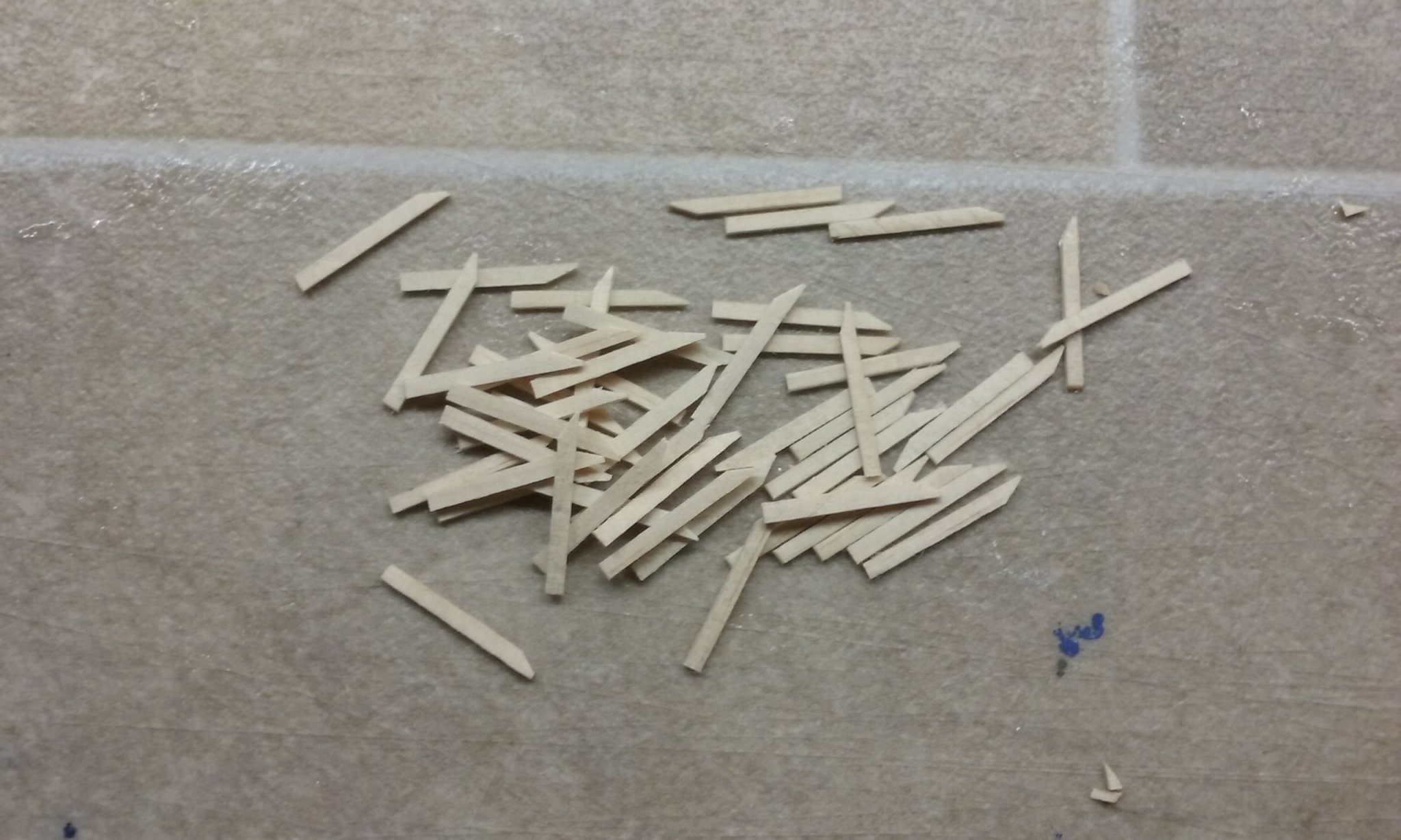
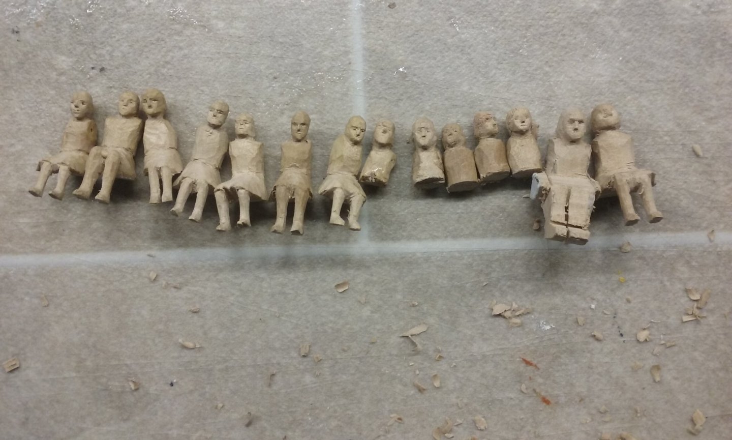
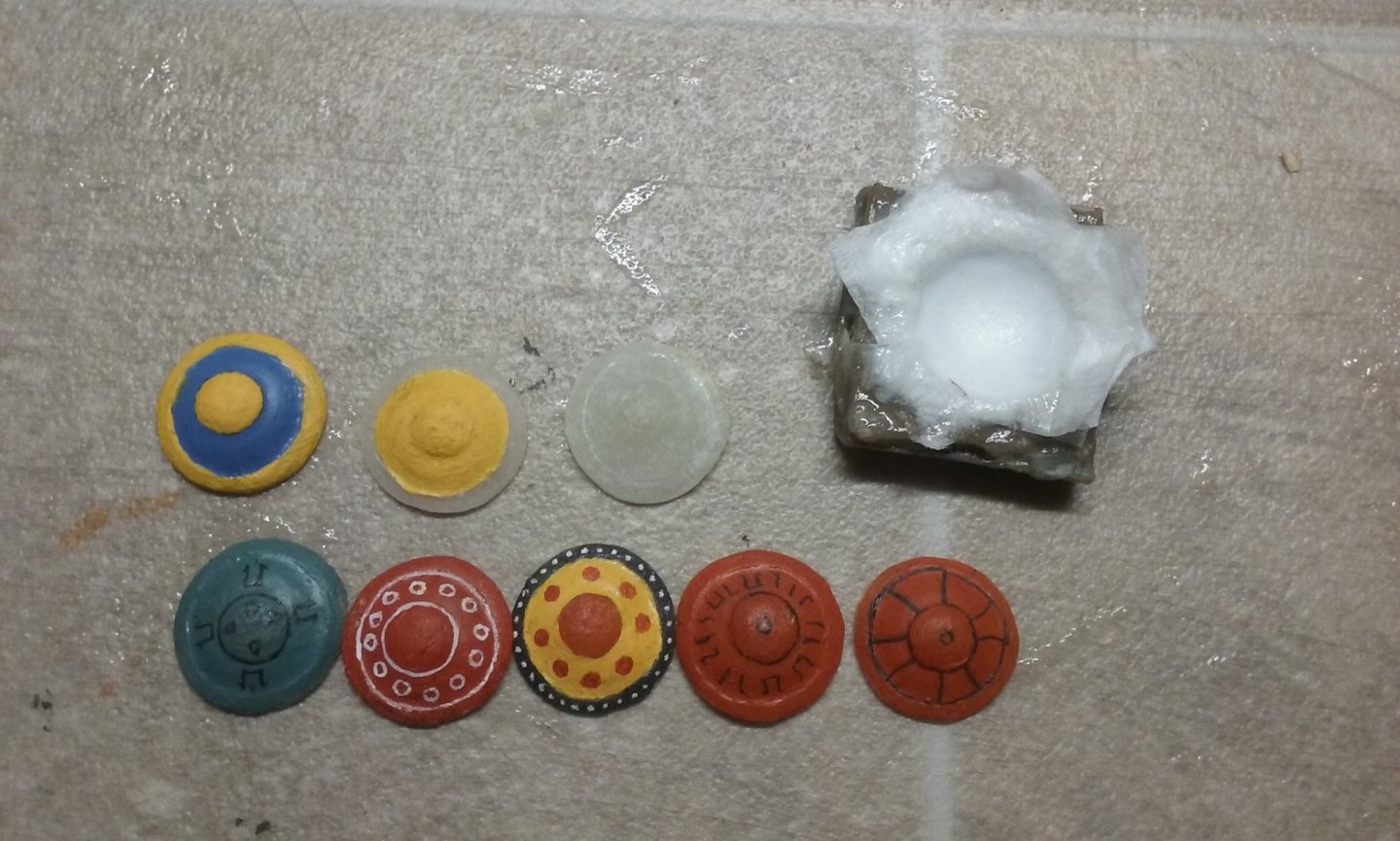
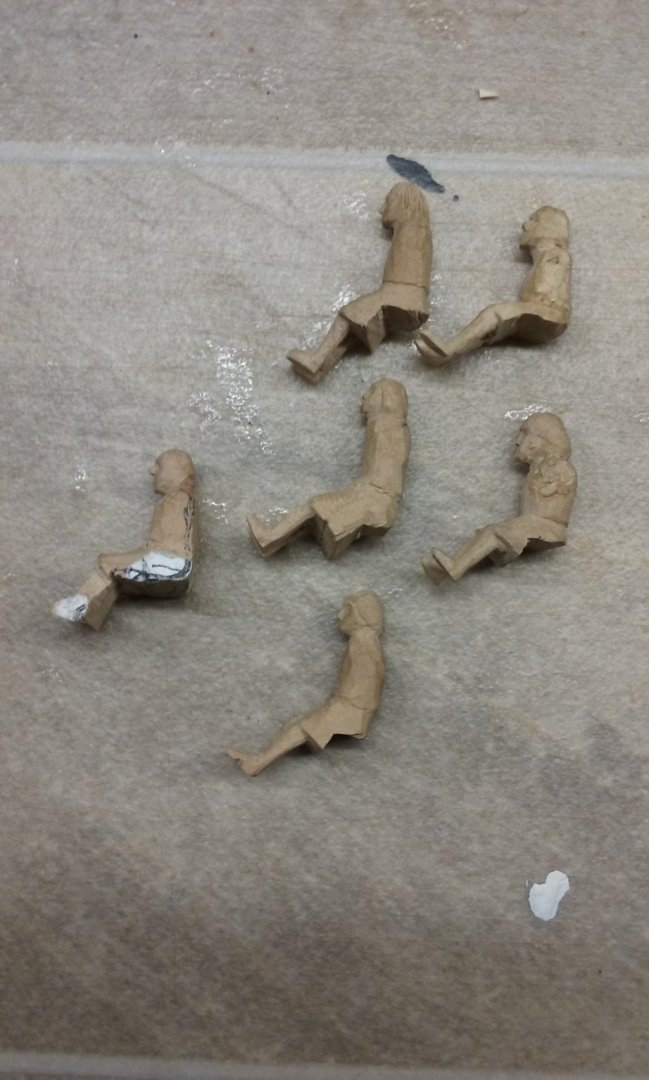
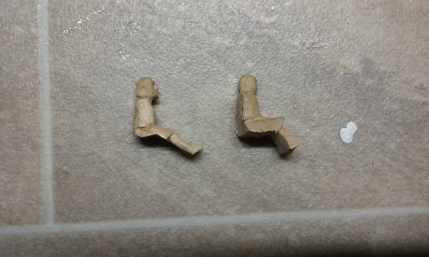
Here are the latest shields. Top row are complete, the lower row are part done. And here are "the boys" so far. I've been carving them roughly to shape and when they're all done I'll go back and do the arms for each one, then smooth them off and make them all pretty. Note the lack of social distancing. Also the 5 who have been cut off at the torso, because I realised I'd done the legs wrong for them to fit onto the benches. I'll have to go back and make lower bodies and legs for these guys, but not till I've got all the rest done. I thought about throwing them out and starting them again, but from the torso upward is ok. I have to say, though, that I'm getting pretty jack of all this wood carving. I have fourteen oarsmen at various stages of completion. I need a total of 48, so I'm not yet 1/4 the way through. There's almost nothing else I can get on with - everything else has to wait on these oarsmen. Add to that I've somehow wrenched my left thumb, so it's getting painful to hold them as I carve. I think I'll take a break from all this and do some work on the Great Harry, which has been languishing unloved for quite a while. Steven

-
HMCSS Victoria 1855 by BANYAN - 1:72
Louie da fly replied to BANYAN's topic in - Build logs for subjects built 1851 - 1900
Beautiful work, Pat. I'm a total klutz when it comes to this kind of work. I tips me lid, sir. Steven- 1,021 replies
-
- 5
-
-
- gun dispatch vessel
- victoria
- (and 2 more)
-
Siggi, I love your crew figures! Am I right in thinking that their clothes are made of paper, and that you rubbed the surface of the carpenter's apron and the painter's overcoat to make them look textured and scruffy? Steven
-
Hi Mike. There's a search function at the top right of this page. Type in the name of the ship, and perhaps the brand of kit, and it should give you a choice of build logs to look at, if anyone's previously made the model. If you go to the Home page, there's also a subsection called Ships Plans and project Research where you can put up questions about your specific ships - and also perhaps find information already posted about them - though the Search function would probably also find those. Good luck with it. Steven
-
What a beautiful model, Dick! Regarding the sails, perhaps if you have the wind abeam with bellying sails off to one side - you'd get the beauty of the sails without obscuring much at all of that wonderful rigging. It's been a while since your last update, but it's certainly been worth the wait! Steven PS: I see you've got the yards supported off-centre. This has been an issue I've been thinking about for quite a while for my own model. Do you have any reason for doing it this way - and do you think this would affect the performance and distribution of forces around the masts?
- 263 replies
-
- 2
-
-
- nave tonda
- round ship
- (and 2 more)
-
Hi from Azores and thank you all in advance
Louie da fly replied to Marco Silva's topic in New member Introductions
Great! Looking forward to following it. Steven -
Hi from Azores and thank you all in advance
Louie da fly replied to Marco Silva's topic in New member Introductions
Oh, and always "dry fit" pieces together before you even think of gluing! (It would be nice if kit pieces were all perfect, but sadly too often they are badly finished, ill-fitting, warped etc.). If something doesn't fit you'll know in advance and be able to fix it before you're committed. You'll save yourself a lot of grief and extra work ungluing and re-doing. Steven -
Hi from Azores and thank you all in advance
Louie da fly replied to Marco Silva's topic in New member Introductions
Hi Marco. Well you'r right - that's a pretty ambitious model for a first timer. But so long as you're prepared to be patient, expect to make mistakes but not be put off by them (or having to do things over), then you've got a good chance of achieving your goal. There have been other first-timers who've successfully completed complex builds, and there's no good reason why you shouldn't as well. But yes, start a build log - it's the best way to get feedback and encouragement, and good advice from other MSW members if you hit problems. Steven -
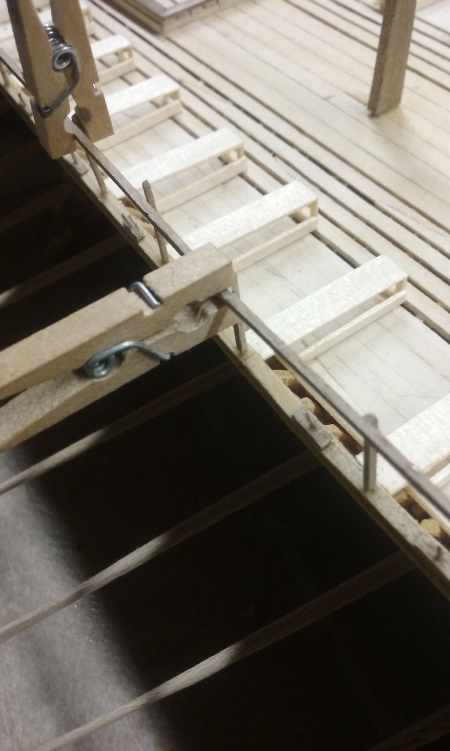
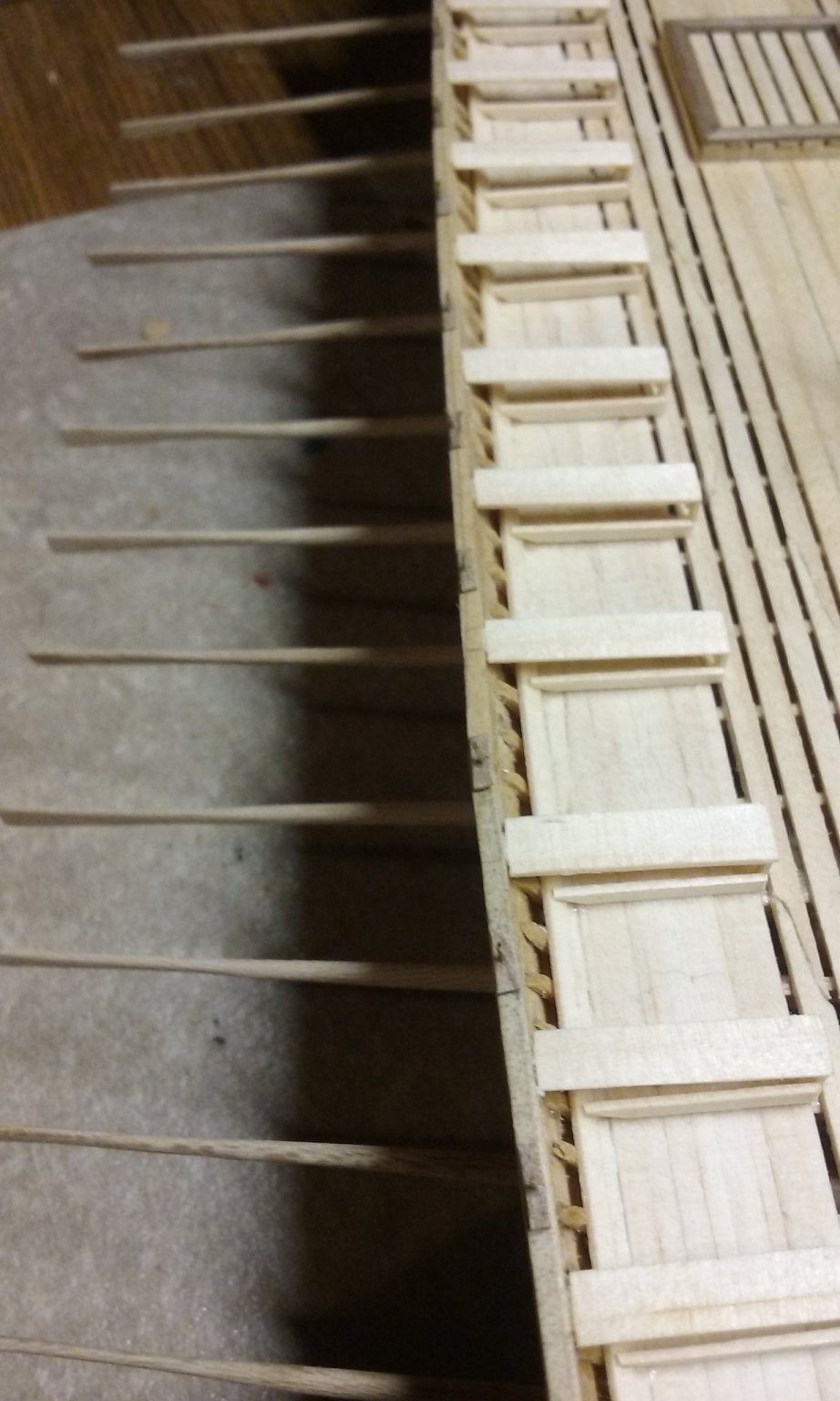
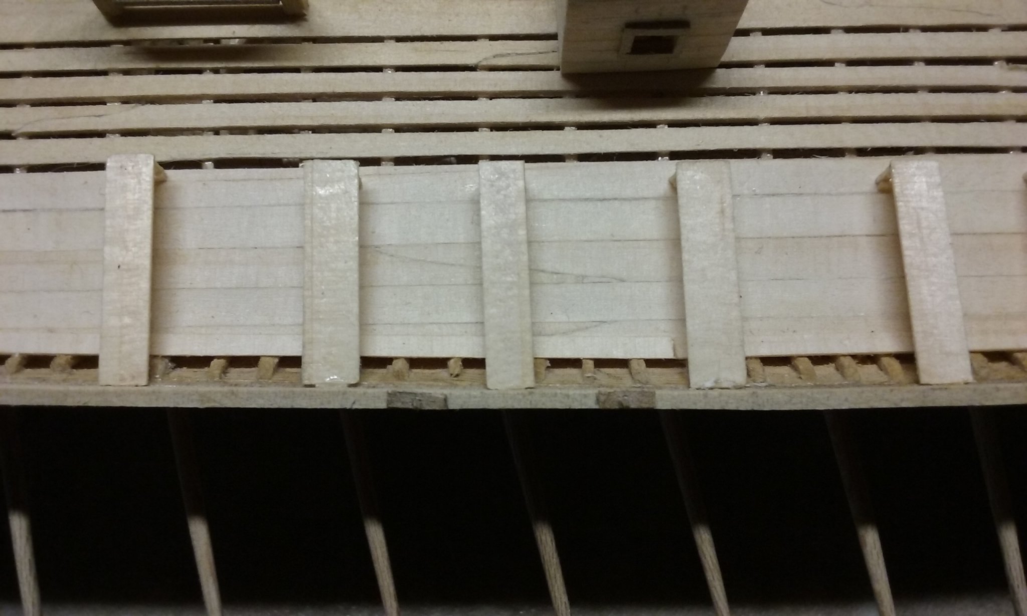
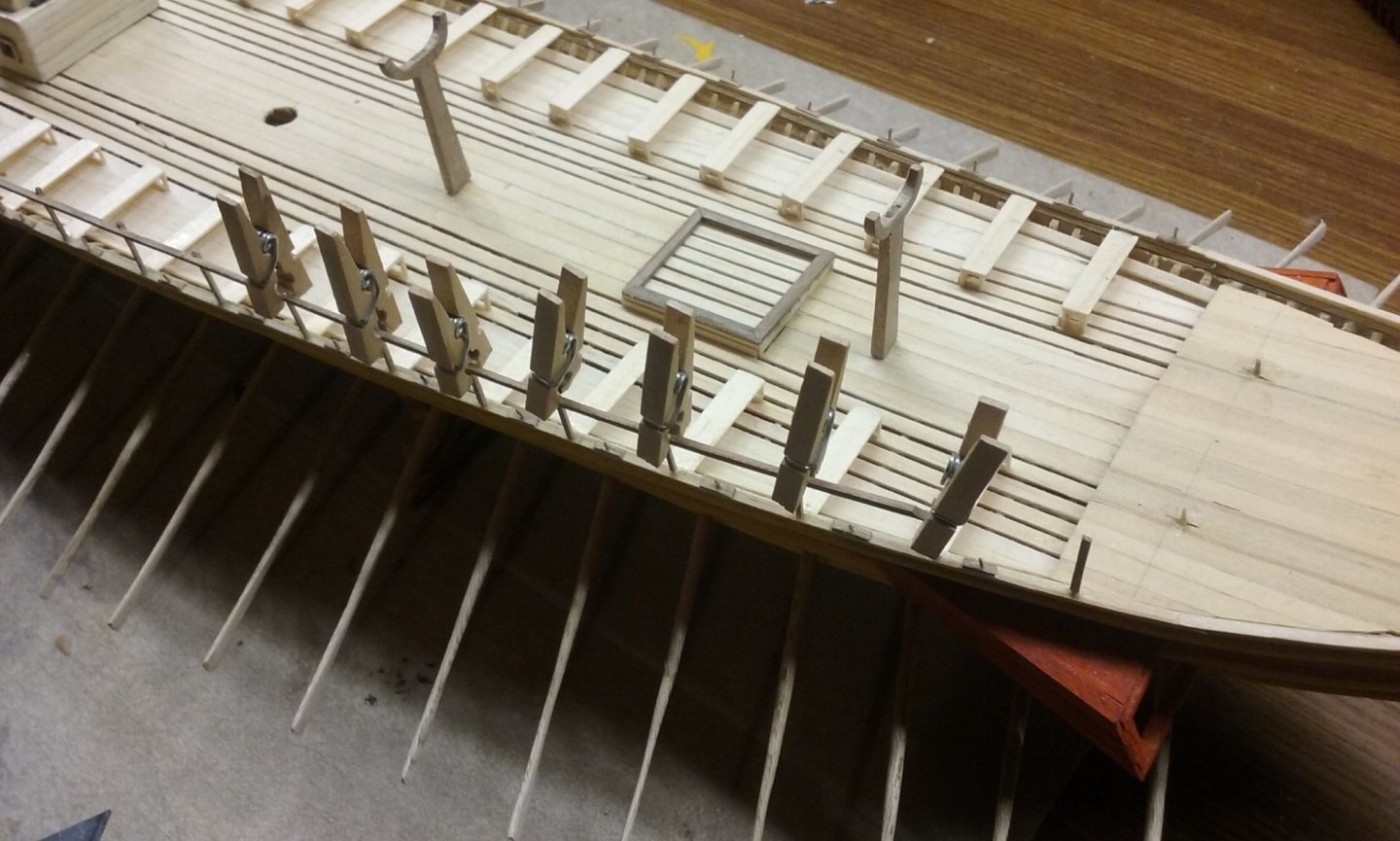
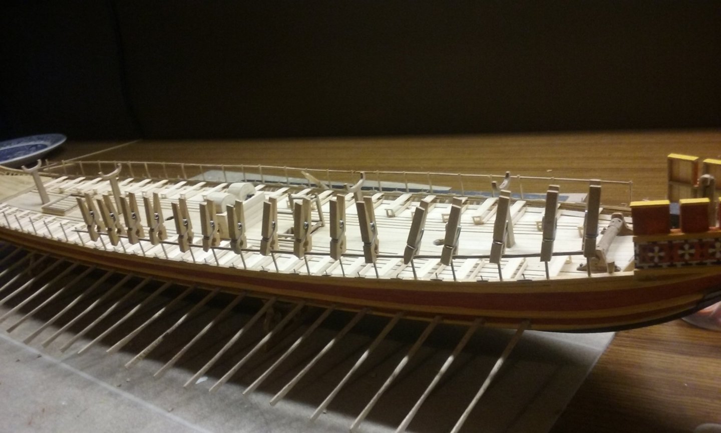
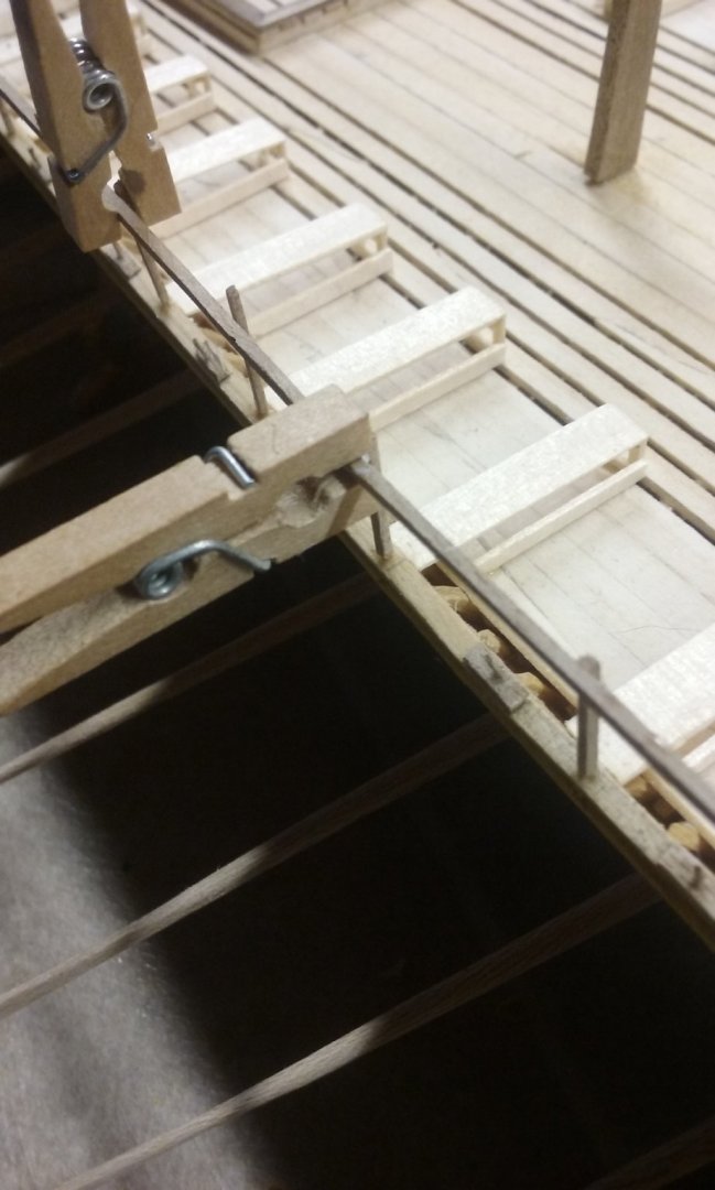
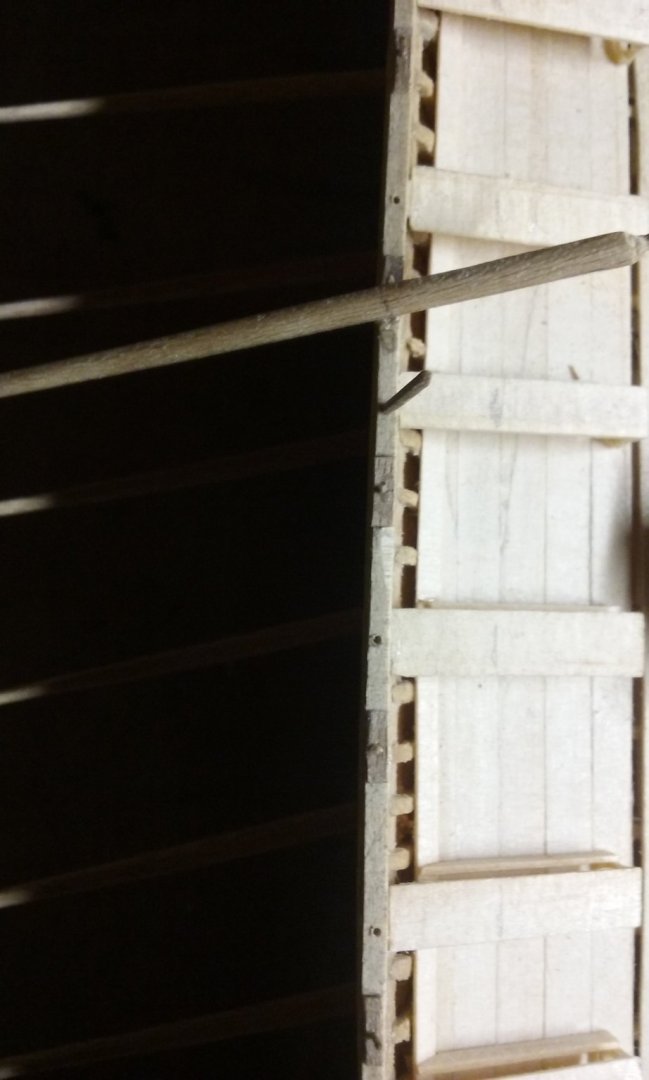
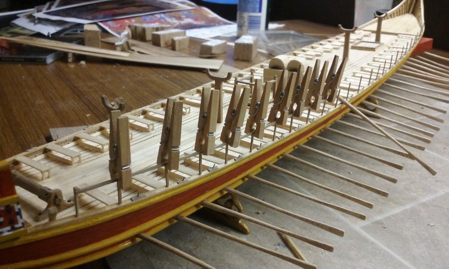
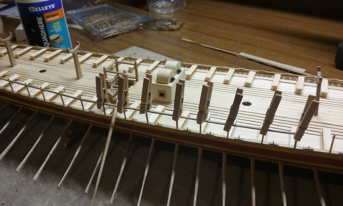
In between times I've been continuing on with making shields - due to the time it takes for the glue to dry, I can only make one a day. Here are the latest ones - five completed, two partly painted, one ready to paint and another in the mould. I now have 26 completed shields - more than half way! I got "on top of" making the oarsmen's arms. Here is the first one. I think I'll be making all the oarsmen with the arms carved separately - it gives me much more flexibility in placing them appropriate to the oarsman's position in relation to the oar handle. Port pavesade nearing completion. (I miscalculated a bit, so I'm going to need a very short bit of railing to finish off) Port pavesade complete and starboard pavesade under way: Uprights in place and the first length of railing glued and clamped. Clamps removed. Note the wood shavings in the foreground, from carving one of the oarsmen. And second length of railing scarphed to the first: So, by spreading my efforts between three different kinds of jobs (four if you count painting the shields as a separate job) I get a steady progress happening, and also don't get bored with the repetitive stuff. Steven
-
Not so sure it's alive. As far as I can see there are no mentions after the middle of the 20th century. The magazines were published in the UK, where the copyright status is "copyright in literary, dramatic, musical and artistic works currently expires 70 years from the end of the calendar year of the author's death. Where the work has more than one author, the copyright expires 70 years after the death of the last survivor of them." I don't know how (if at all) that applies to the publishing company, which I suppose would be the owner of the copyright, even though a lot of the content was written by private contributors. An interesting legal puzzle. Steven
-
Thanks everybody for the likes. md1400cs, much of the "history" is speculation - trying to reconstruct what a dromon must have been like based on very patchy evidence from 1000 years ago, in Greek (so you have the added problem of translation difficulty and alternative meanings in English for Greek words - what exactly did they mean when they wrote that? And some technical terms just no longer exist in Greek, so the "meaning" is based on educated guesswork). I'm very lucky the book Age of the Dromon exists - its my main source of information and guides me in many of my reconstructive choices. But there are many things even that source leaves open - just how do you construct a pavesade? Where exactly does it sit on the hull? Do the shields overlap the gunwale? A lot of educated guesswork needed when making the model. But to me that's a lot of the fun - working out how it must have been - or how it may have been, given the available evidence. As much of a detective story as a build log. And I find that very enjoyable. I'd rather try to figure out how a ship went together than have the plans handed to me on a plate. Others may feel very different, but that's how it is for me. Steven
-
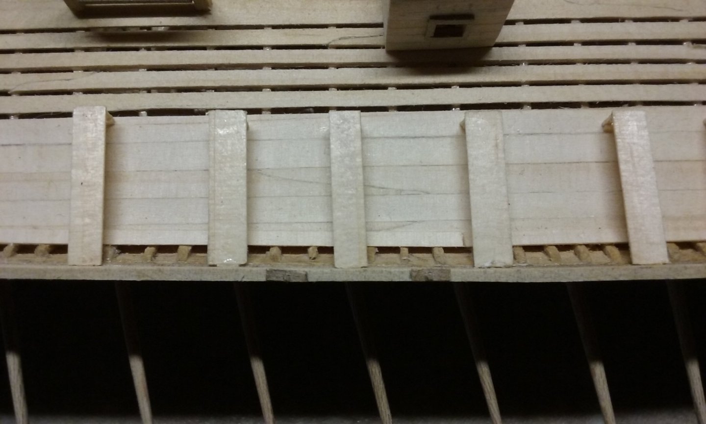
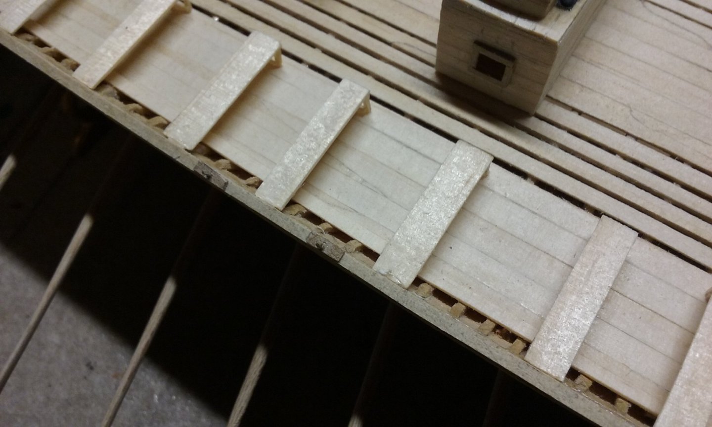
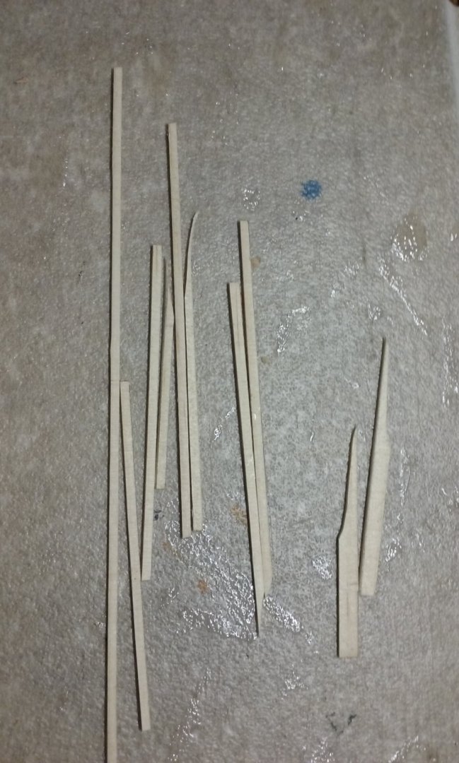
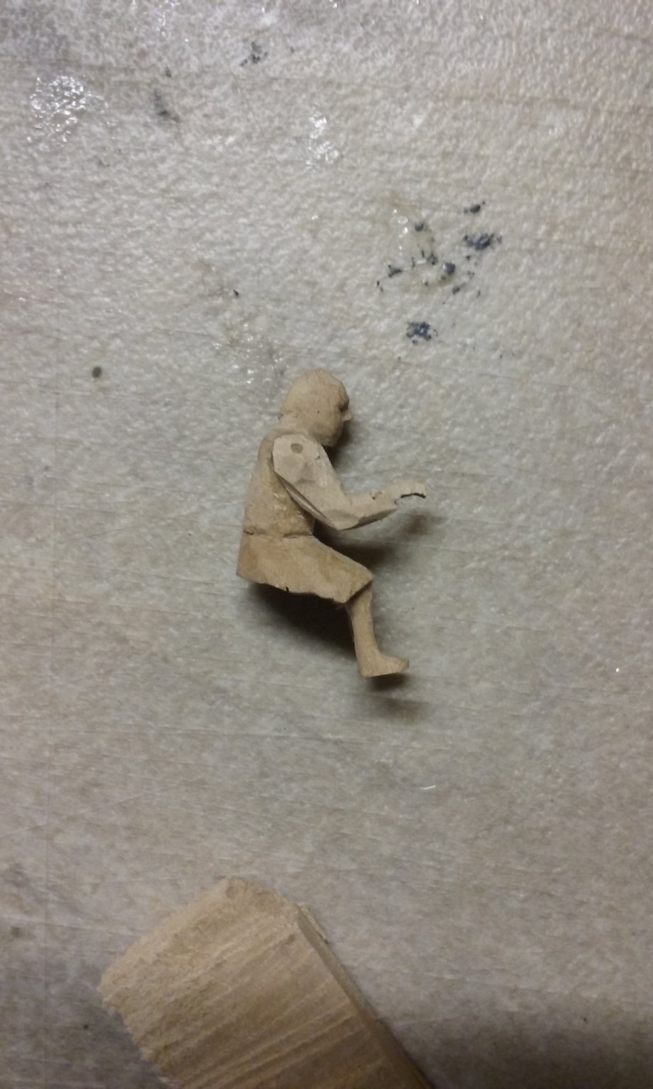
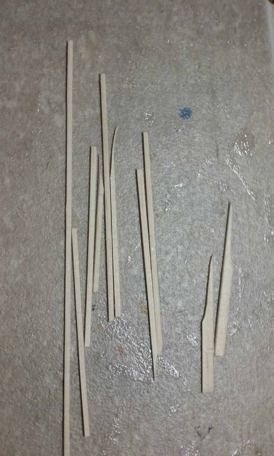
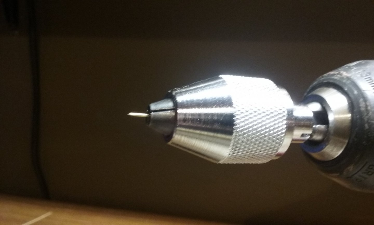
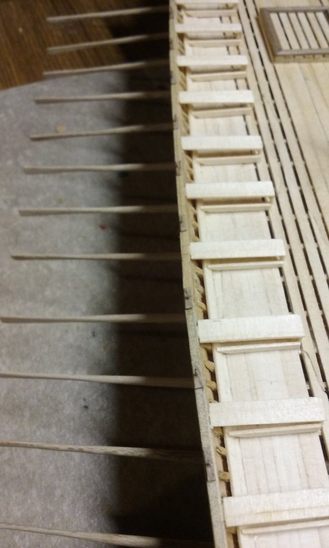
I've made all the uprights for the pavesade: Drilling holes in the port gunwale to take the uprights (using a brass pin about 0.5mm diameter as the drill-bit). First upright in place: And all done on the port side: And adding the railing. First section: Second section -joined to the first with a scarph joint. More to come on this. Now I'm working on the arms for the upper oarsmen. I've been dreading this - difficult to get exactly right. I worked up a couple of arms in plasticiene, then using that as a guide I cut out some very rough and oversize arms from pear wood. Shaved one down at the shoulder-end until it fitted to the body,then stuck it in place with a wooden peg joining the arm to the body. Sorry, I didn't take photos at this stage. Then started carving the arm till it fitted, holding the oar handle with the oar in place. Not a perfect job - I cut too much off the hand and the shoulder is too wide (unless he's Superman). I can't do anything about the shoulder without trimming off the wooden pin that holds the arm to the body, and the hand will have to be re-done as part of a new arm. But that was to be expected - this was the test piece, and will serve as a model to make the others from. Steven


-
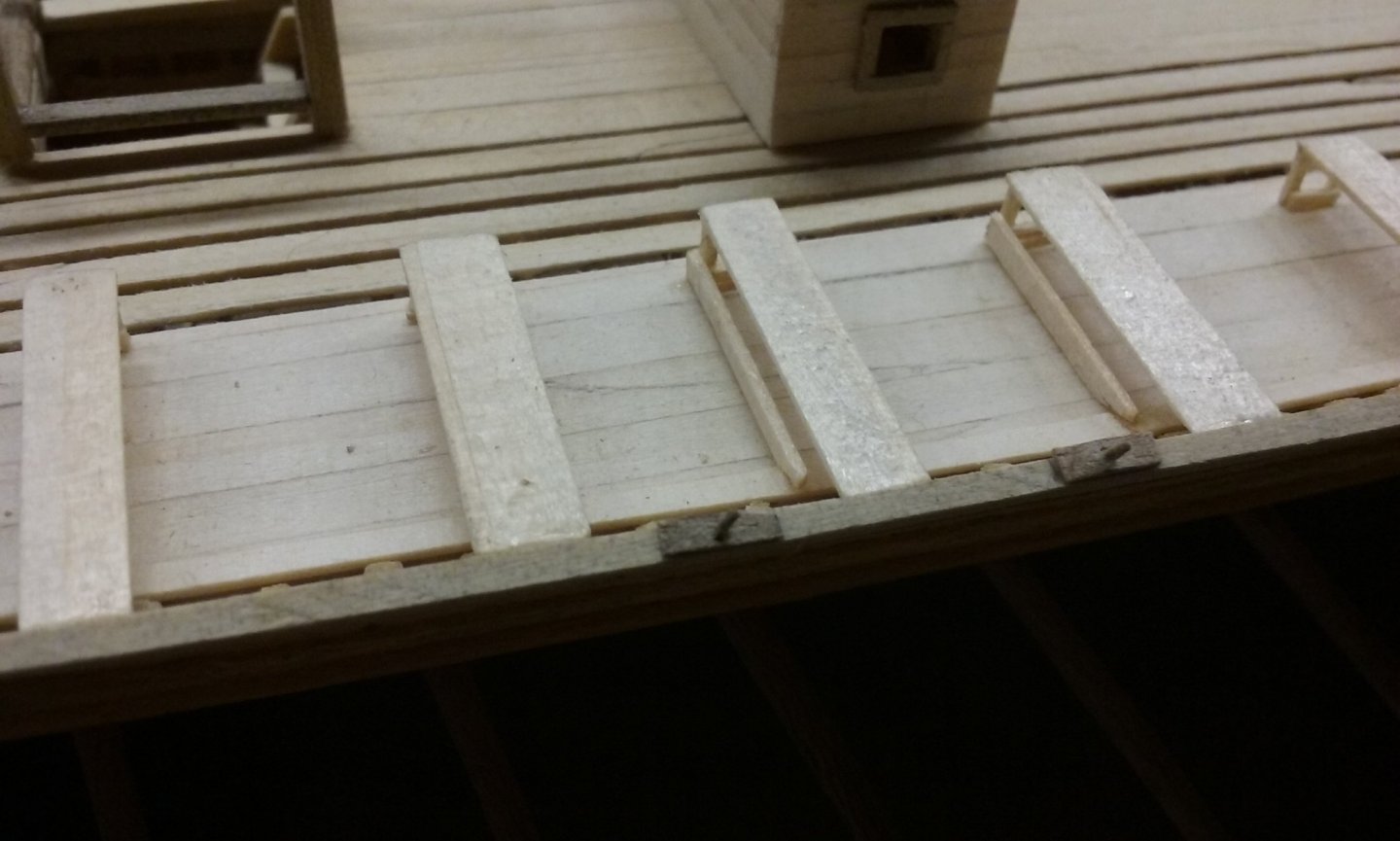
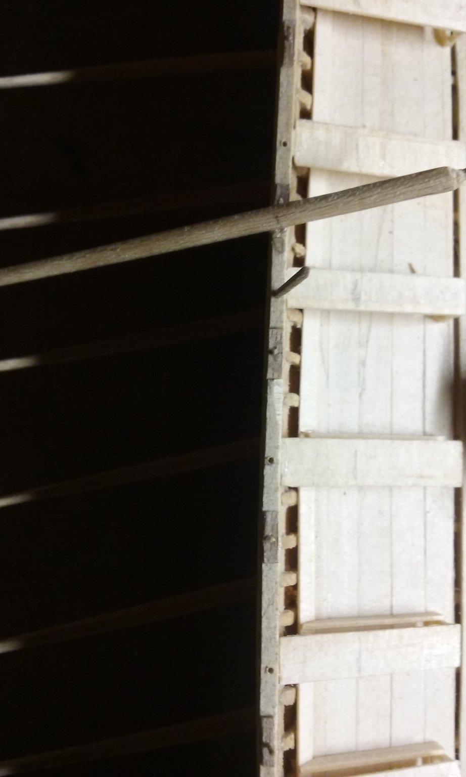
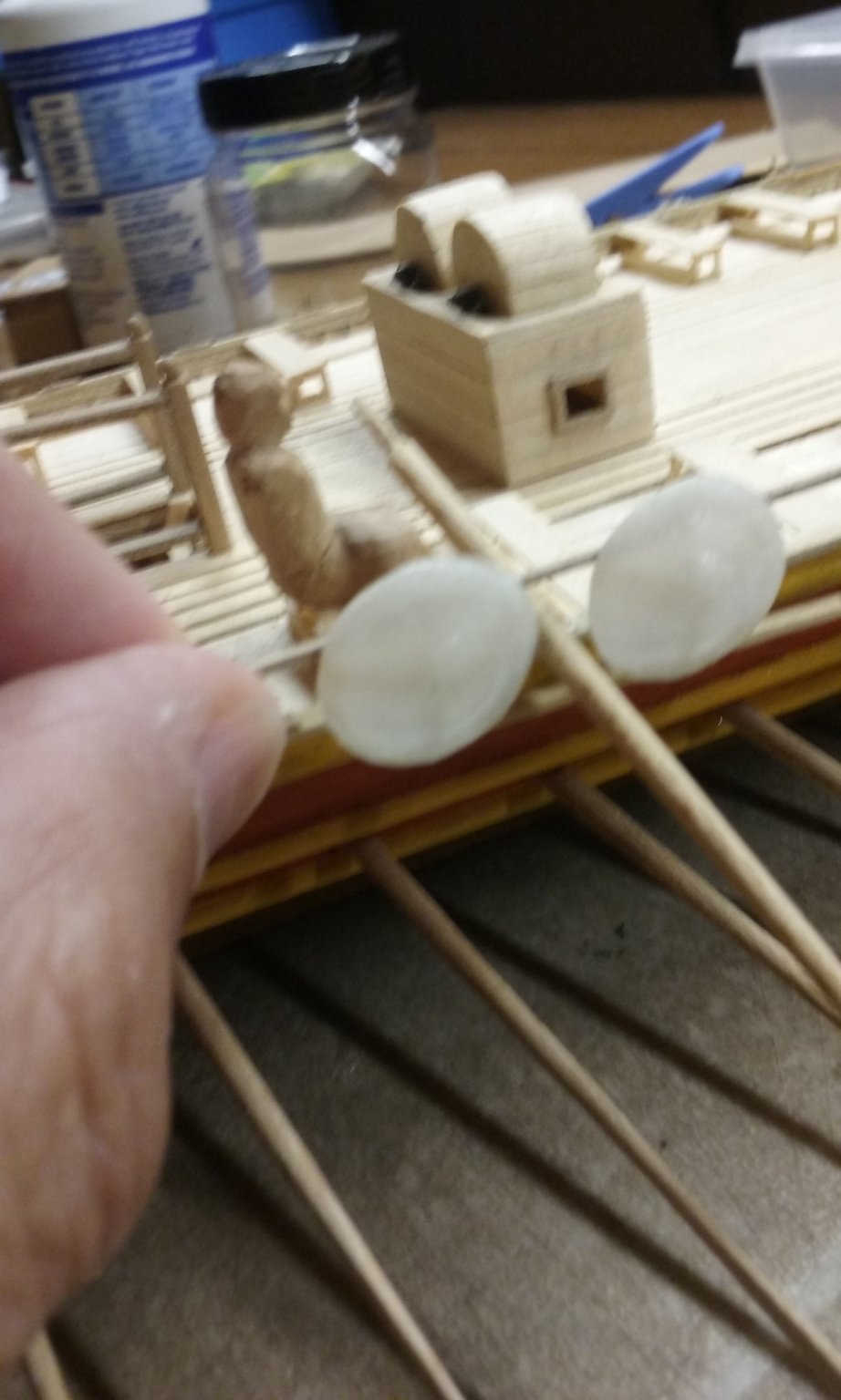
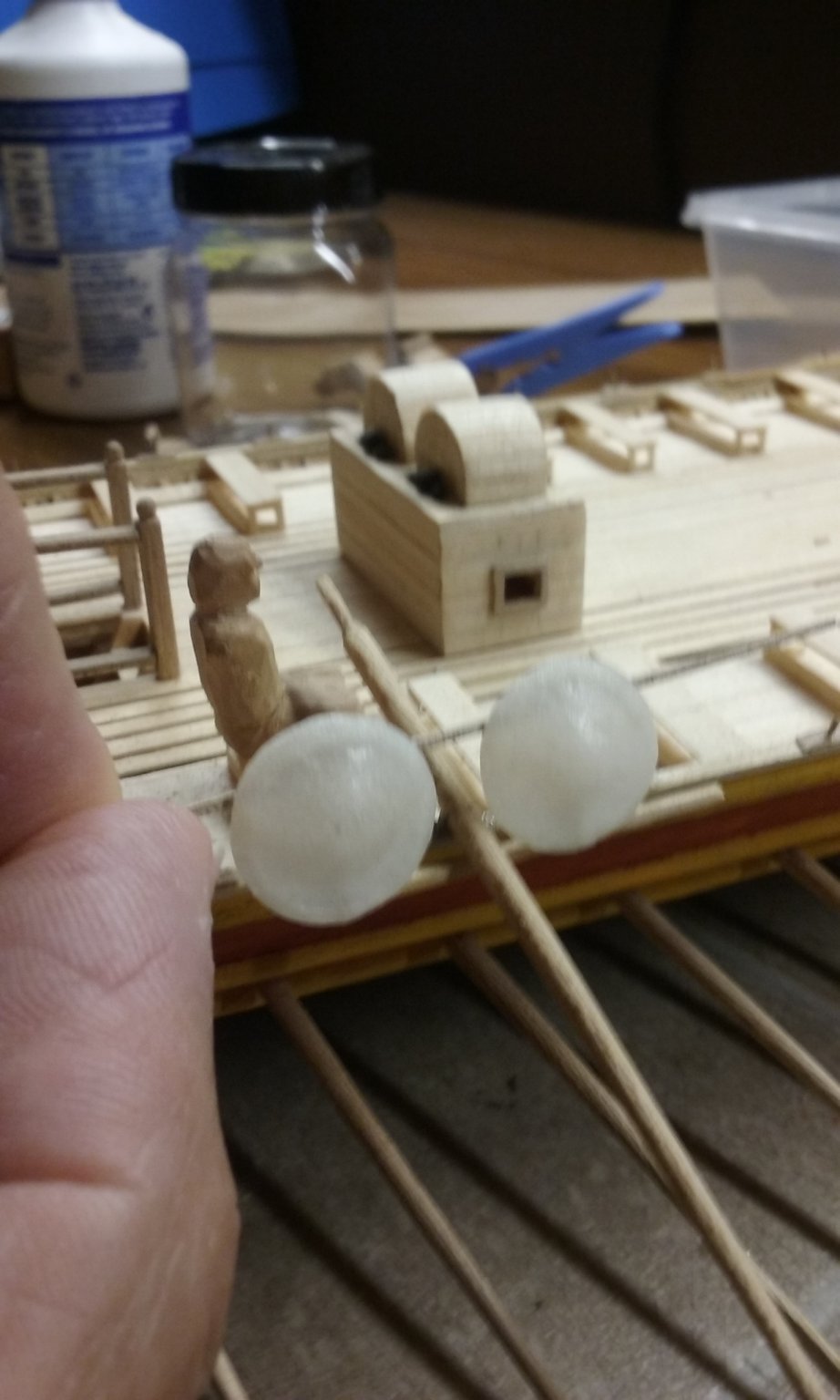
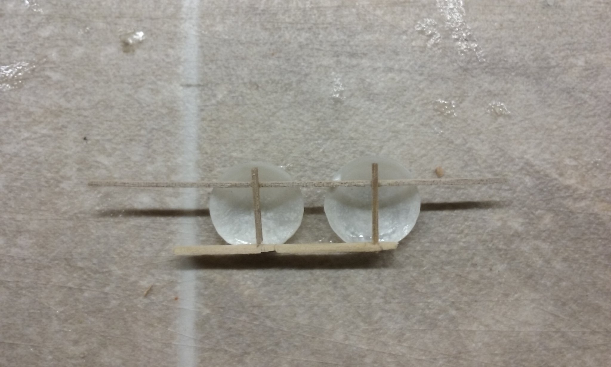
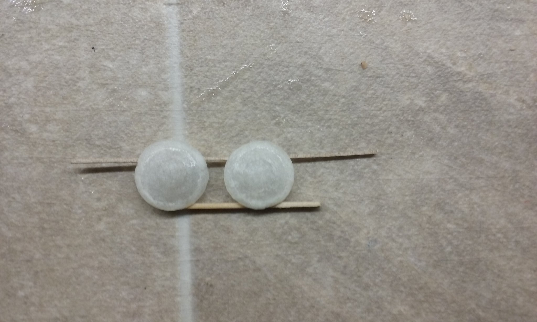
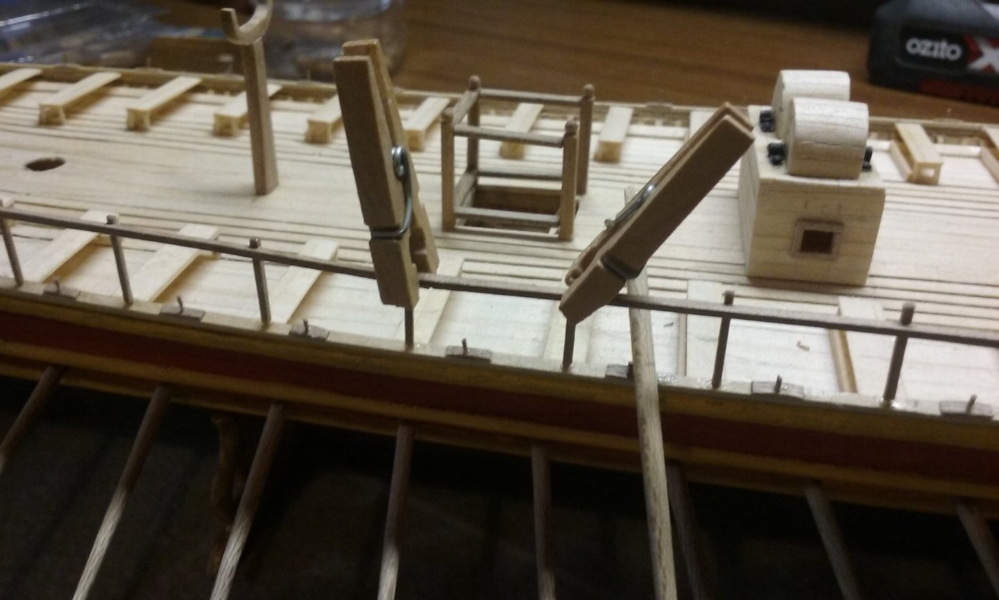
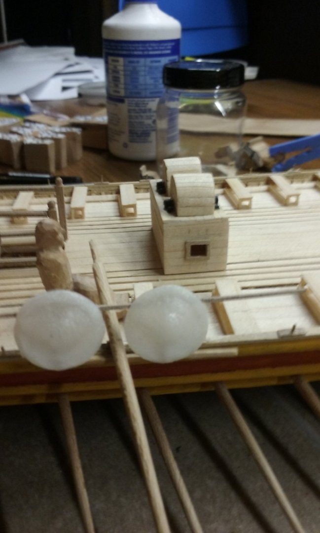
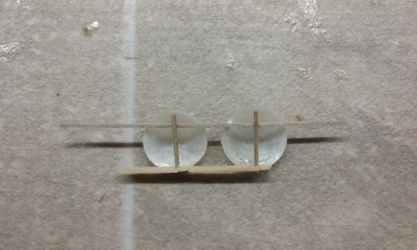
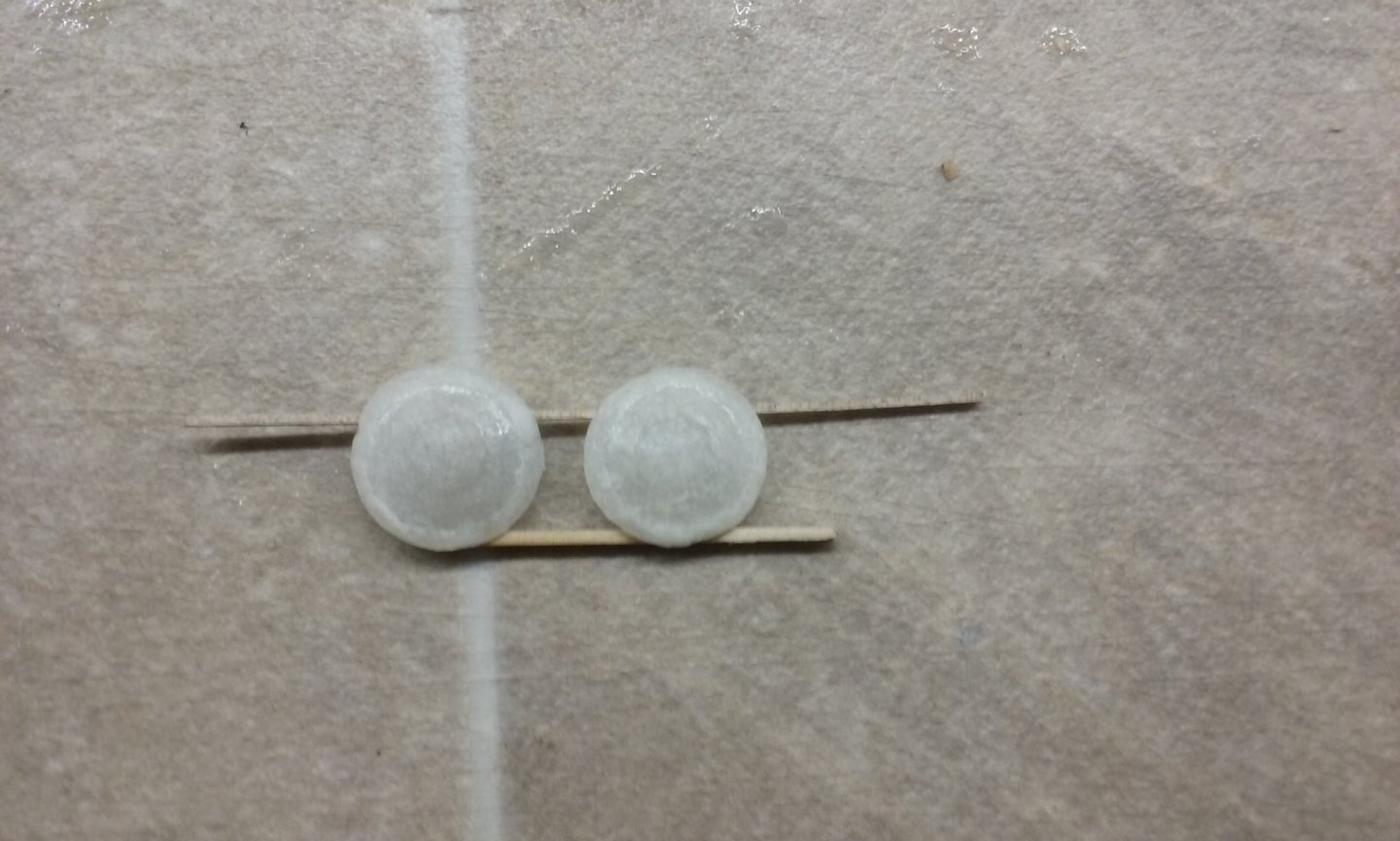
It just keeps on coming - I'm on a roll! Trying out the prototype for the pavesade. Front view: Back view: The lower beam represents the gunwale - the uprights will be stuck in holes in the gunwale, in line with the oarbenches. And held in place by hand, to line up with the oarbench and the thole: Looks like it'll work - just enough room between the shields for the oars to move unhindered. So I'm happy to go ahead with this arrangement on the ship itself. Steven


-
Hi to all from Tijuana MX.
Louie da fly replied to Sergio Camacho's topic in New member Introductions
Thanks for the photos. Looking forward to seeing your build log. When I was in Southampton UK about 11 years ago they had the whole upper floor of the Maritime museum there devoted to a Titanic display - it was the port she left from on her fatal voyage. I don't know if they'd still have the display, but the museum might be a useful source of information for your model, and perhaps could refer you to others. Just out of interest, is there anything in particular that drew you to make two models of the Titanic? Steven -
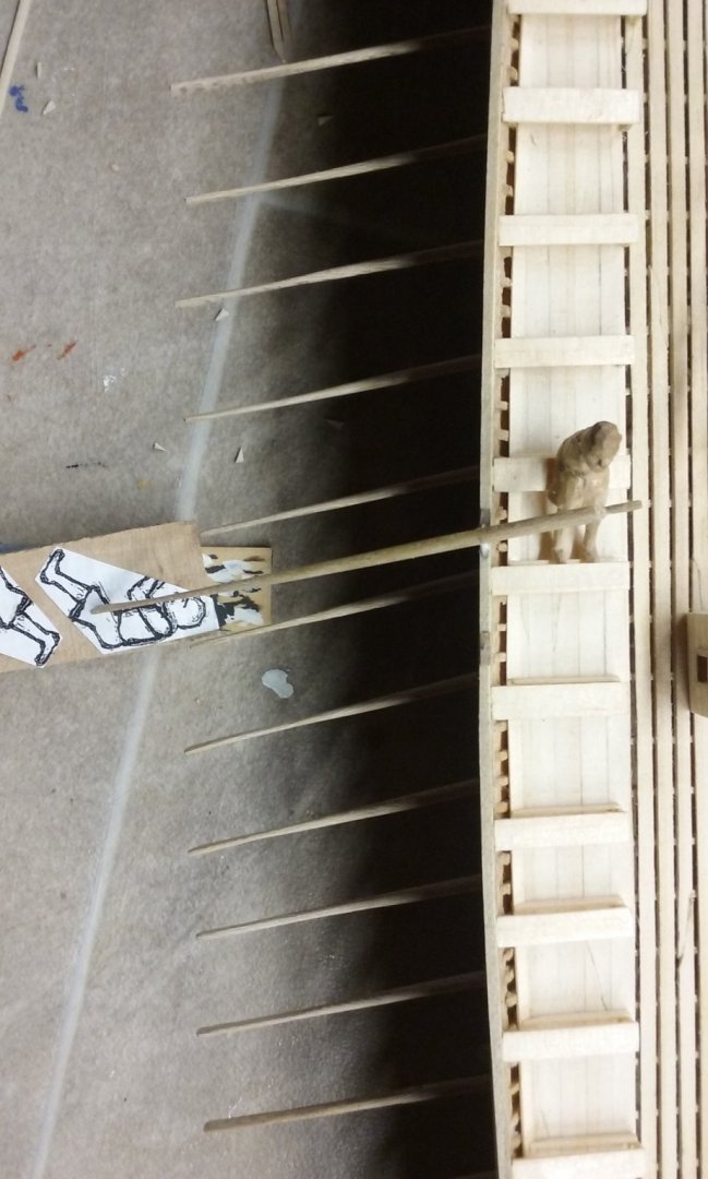
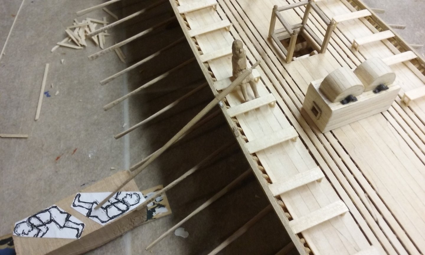
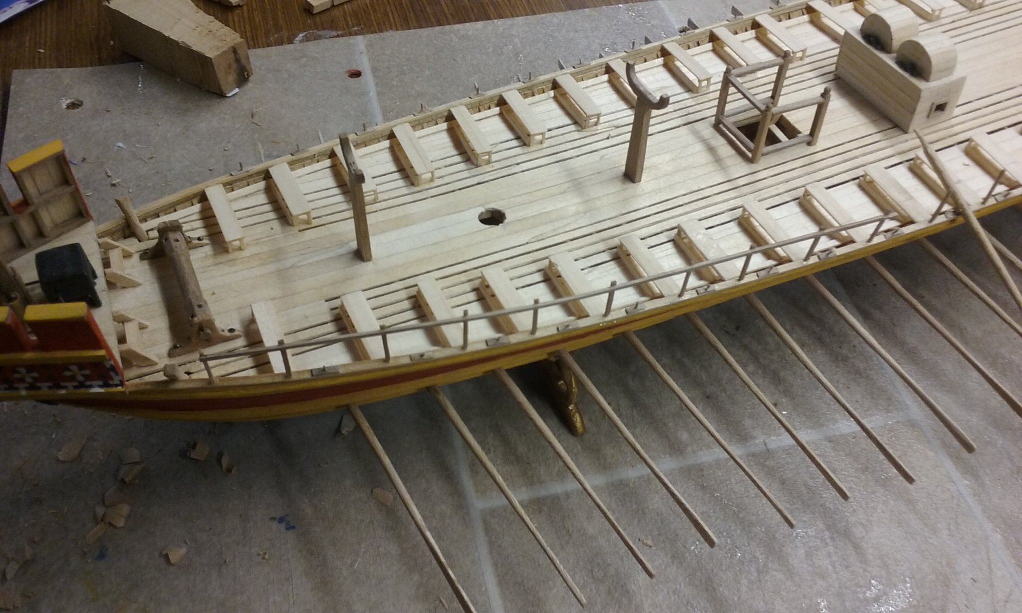
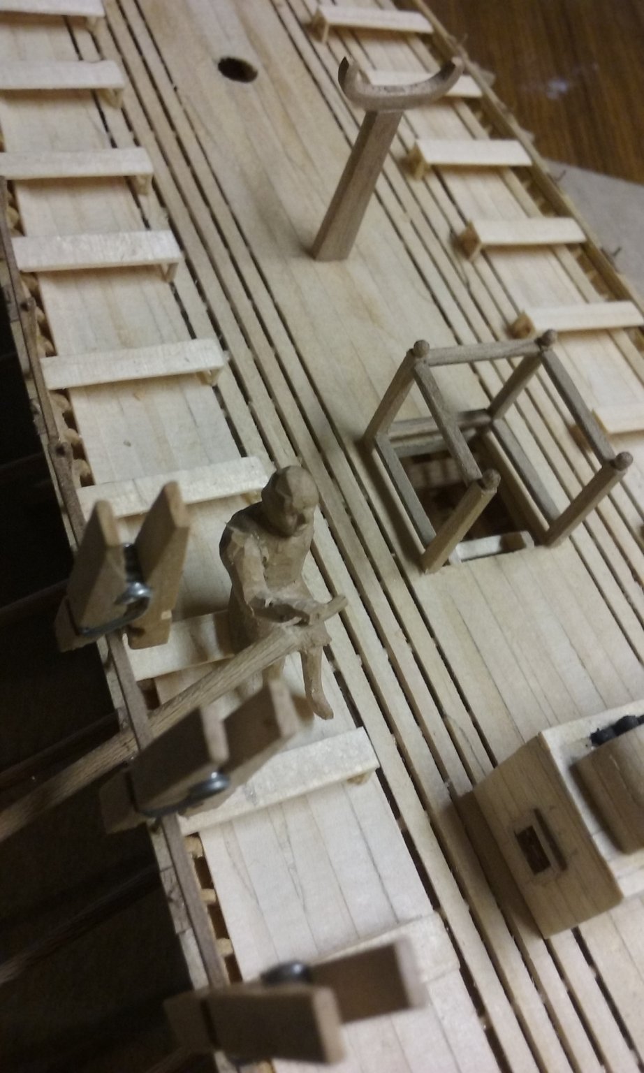
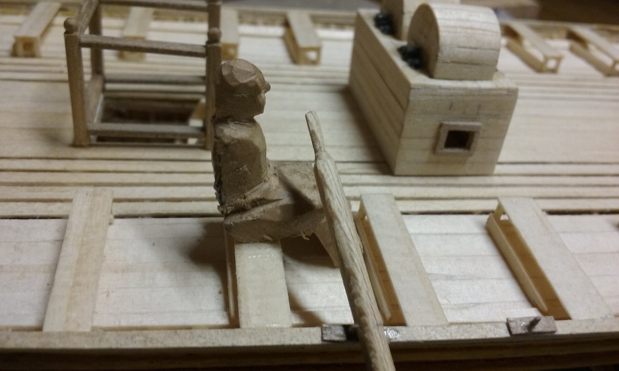
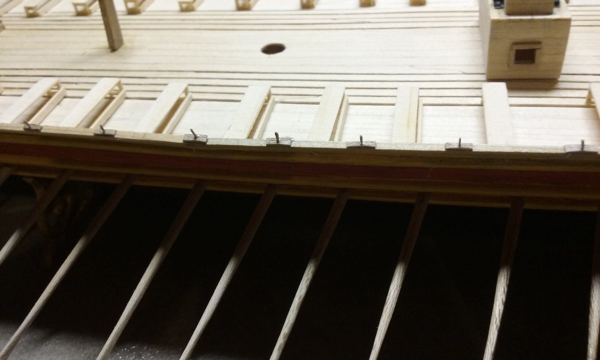
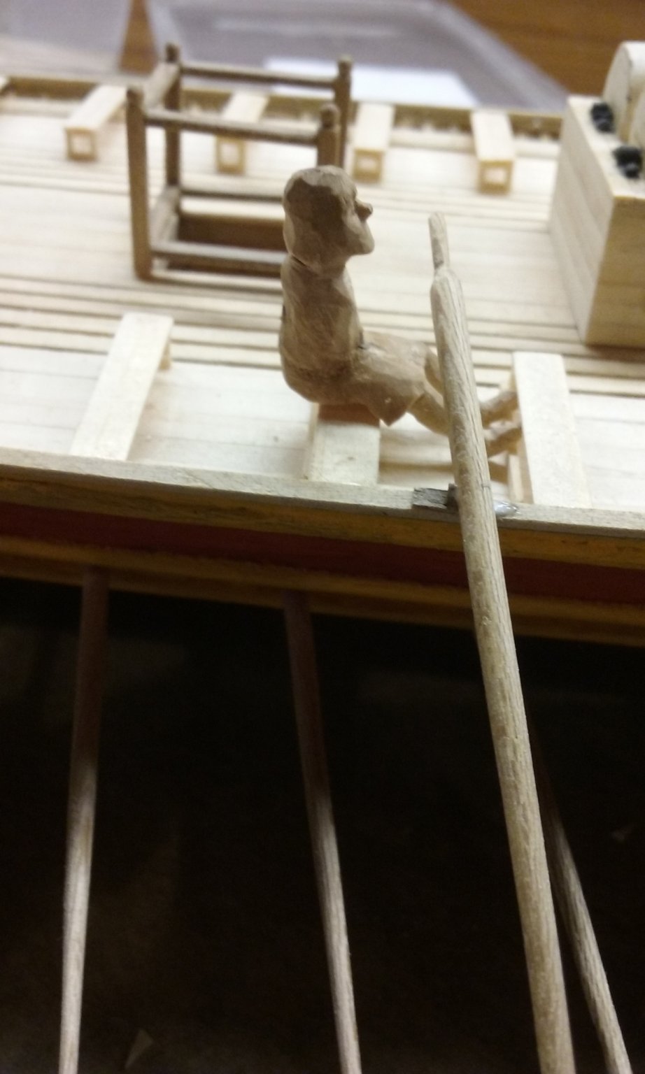
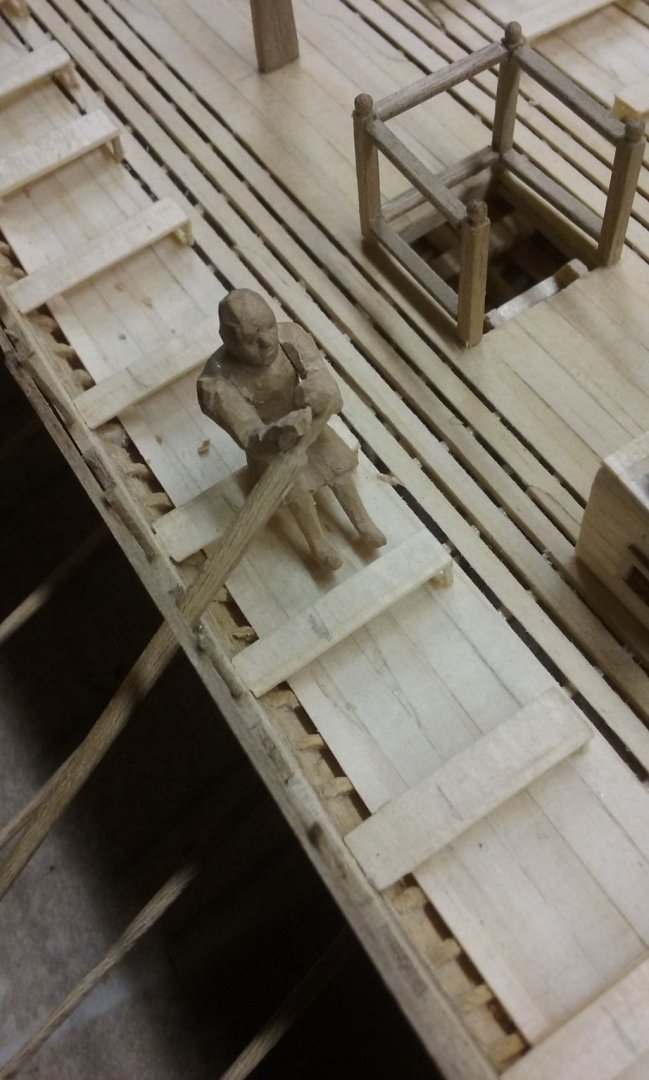
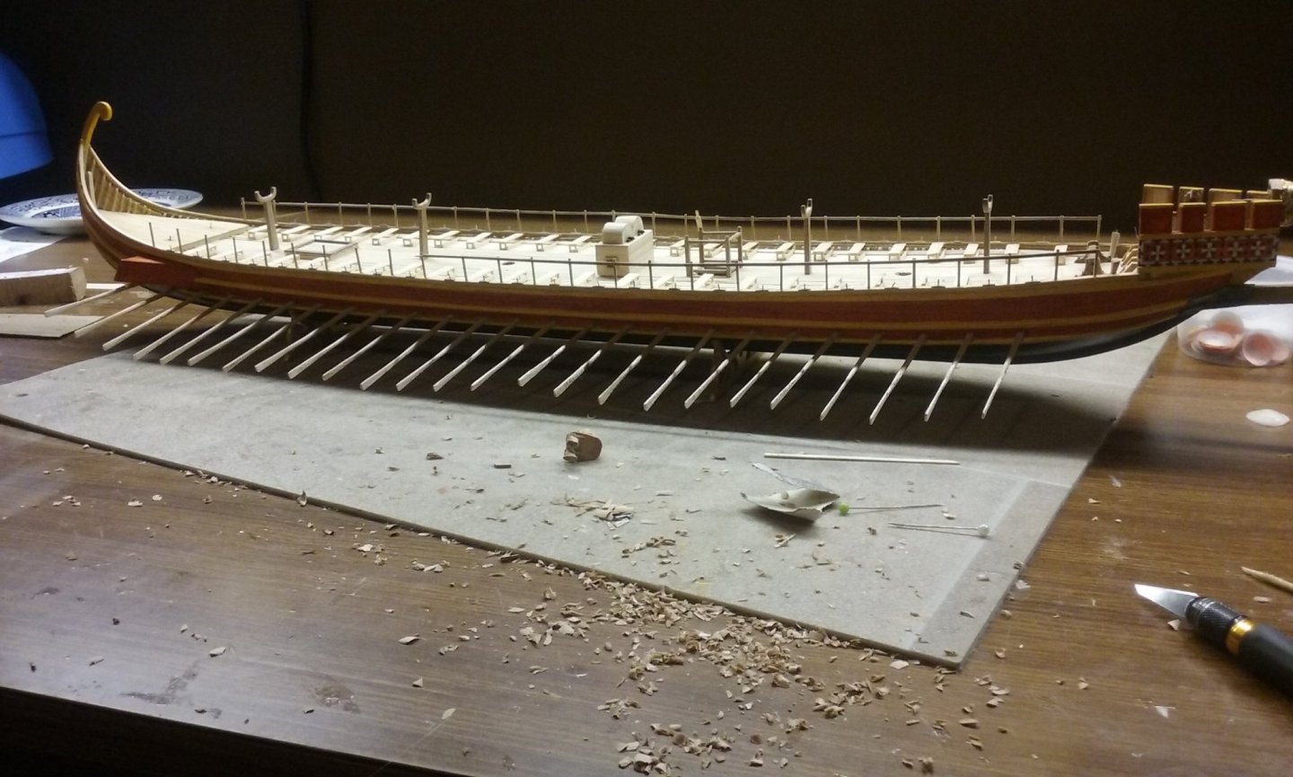
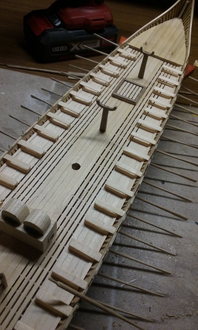
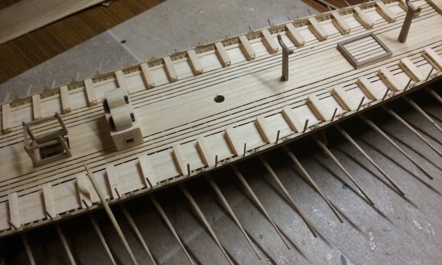
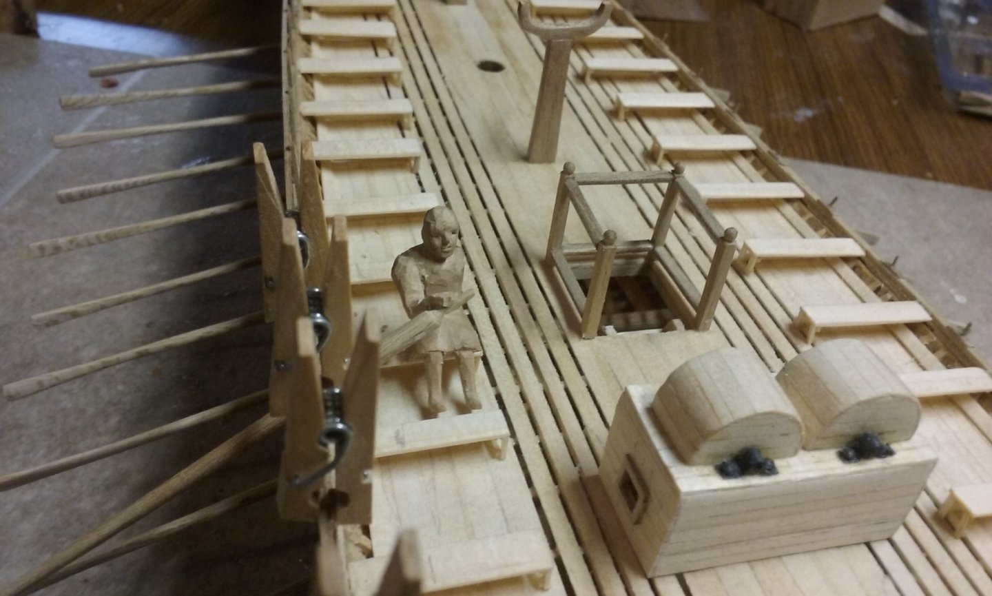
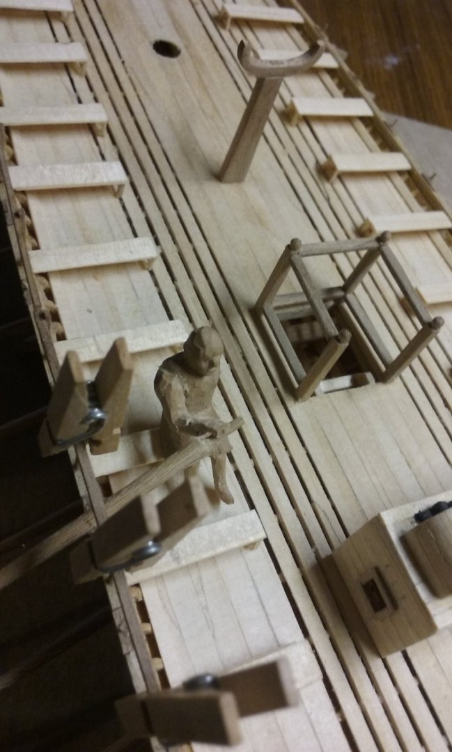
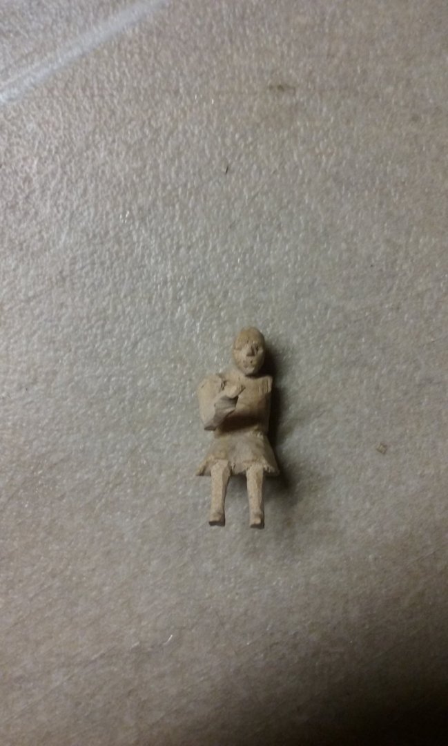
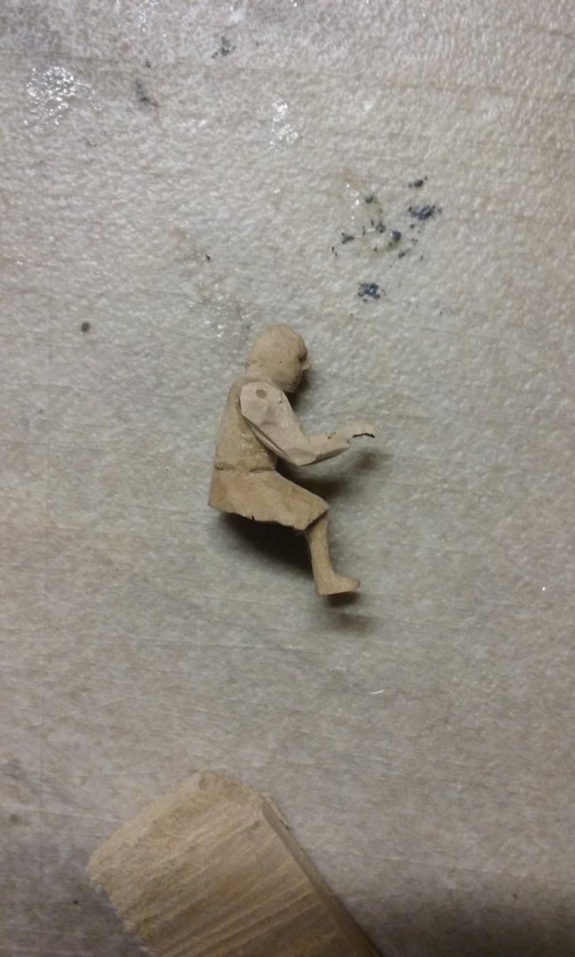
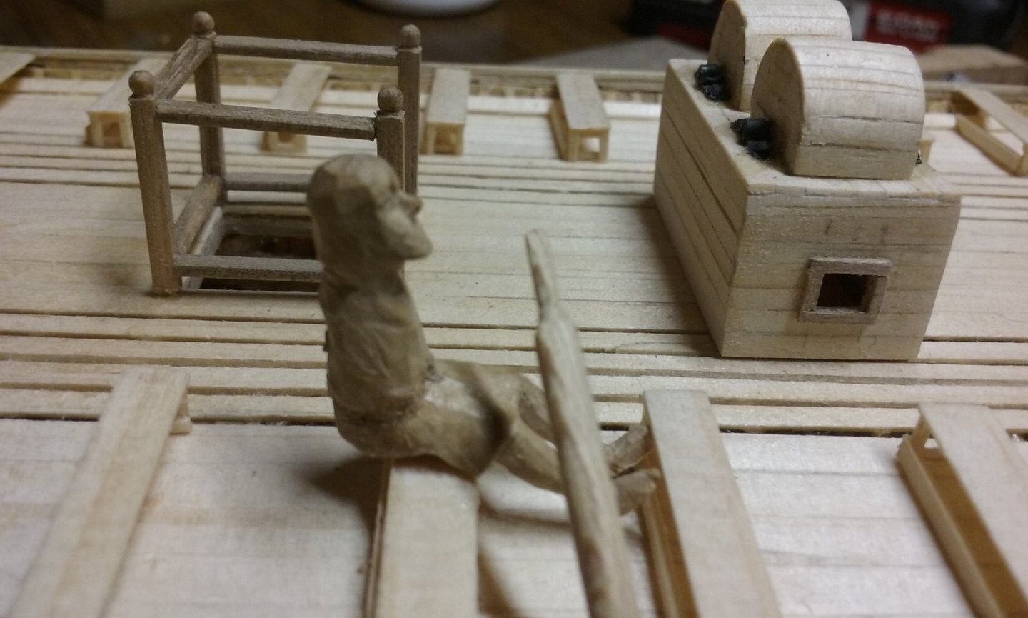
Thanks for the likes, people. Latest progress - stuck at home, so apart from the work needed around the house and garden I'm free to work on the model. Now I've got all the tholes glued in place: It certainly adds to the "look" of the model, but now I'm going to need to be more careful picking it up so I don't break anything. And now I've been able (finally) to get the relationship sorted out between the ship, the upper oars and the oarsmen, I've discovered that the first few oarsmen are the wrong shape - they have their legs extended too far, which means they can't fit properly between the oarbenches without their bottoms overhanging at the back: So I made another guy with his knees bent more (the one on the right - you can see the difference between him and the guy on the left): And he fits nicely: So I now have half a dozen oarsmen with the wrong legs: My first impulse was to toss them out and start again - but that would have wasted all the effort I put into modelling their heads, faces and torsos, which are totally ok. It's only from the waist down that they're wrong. So I'm going to cut each of them in two and make new "below-the-waist" bits for them. I can glue them together with a rod between them and everything should be hunky-dory. Next steps: 1. sort out how the oarsmen's arms are going to work - I'll use plasticiene (modelling clay) to get the shapes roughly correct, and then make some in wood and try them out. 2. Put in the oar-racks (vertical posts at each bench, between the side of the ship and the oarsman). 3. Make the pavesade (the support structure for the shields at the side of the ship). Not necessarily in the above order. 4. Once all that's done, I can get onto putting the upper oars in place. Each of these will take some practical experimentation, and quite a bit of work, so I won't be getting bored. Steven


-
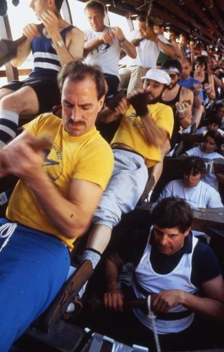
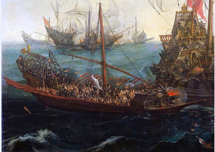
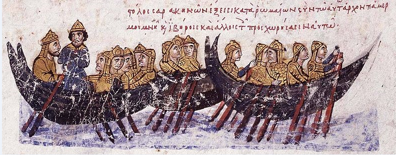
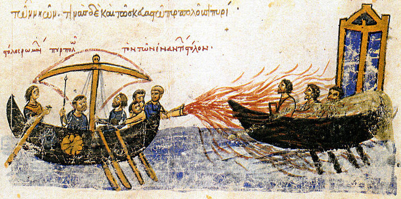
Mark, I'm very interested in the effects of oarblade shapes. I note that the blades of the Olympias were sort of leaf-shaped, (see 0.52 and onward at but ancient Greek representations of oarblades (usually on pottery) show them long and straight-sided: or short and straight-sided: many renaissance galleys seem to have had blades that tapered very gently and went quite a long way up the loom: similar to those shown in Byzantine representations: I'm very interested in the mechanics of all this - I wonder if there are any publications relating to it. [Edit: Silly me. Of course there are - a quick google search turned up this: https://www.researchgate.net/publication/245524939_A_review_of_propulsive_mechanisms_in_rowing - very good for those of a scientific/engineering mind-set; not so much for people like me. The thing I'd really like to see is a a follow-up to this research, giving a scientific analysis comparing the performance of different-shaped oar-blades Steven

-
I agree with Backer. Contact cement is very unforgiving, not to mention having really nasty fumes. Once you put your plank down you're committed, with no chance of fixing mistakes. White (poly vinyl acetate) glue allows you time to adjust things a bit, and believe me, you'll need it every now and then. As this is your first build, give yourself as much leeway as possible. You'll still make mistakes - we all do. But they needn't be disasters. Use the smallest amount of glue you can get away with but still be able to do the job. And wipe off excess immediately (a wet rag or wet paintbrush is good). A lot of people use a half and half white (PVA) glue/water mix - the thinner glue still works but doesn't make as much mess. And planking should be taken bit by bit - hurry is your enemy. Take the time to get it right and it won't sneer at you (as some of my own mistakes do to me) down the track. Good luck with the planking. I think the 4mm will look better, and 'jogging' will add to the "realness" of your model. And always ask questions if there's anything you're not sure about. There are plenty of people on this forum who'll be very happy to give you the benefit of their experience. Steven
-
Hi to all from Tijuana MX.
Louie da fly replied to Sergio Camacho's topic in New member Introductions
I hope you do start a build log and I look forward to seeing the progress on your Titanic. I'd expect a 1:400 model to have a lot more detail than the 1:700 - It would be interesting to see how much extra. Steven -
I just googled it. That's a seriously attractive vessel. And yes, certainly start a build log. You'll find a lot of help from members, as well as a lot of encouragement. You'll still make mistakes - we all do - but you'll also be able to get help in correcting them from people with lot of experience, who've probably made the same mistakes themselves as they learnt the ropes. Looking forward to seeing Katy's progress! Steven
-
No Mark, it's based on contemporary pictures. See my post #91 on page 4 of the build log. I started out with blades copied from the book Age of the Dromon, but decided to change them all to mirror more closely the picture in post #91. A lot of work, too, but I think worth it. Even then, perhaps I haven't got it exactly right as the taper in the picture seems to go a long way up the loom. Steven
-
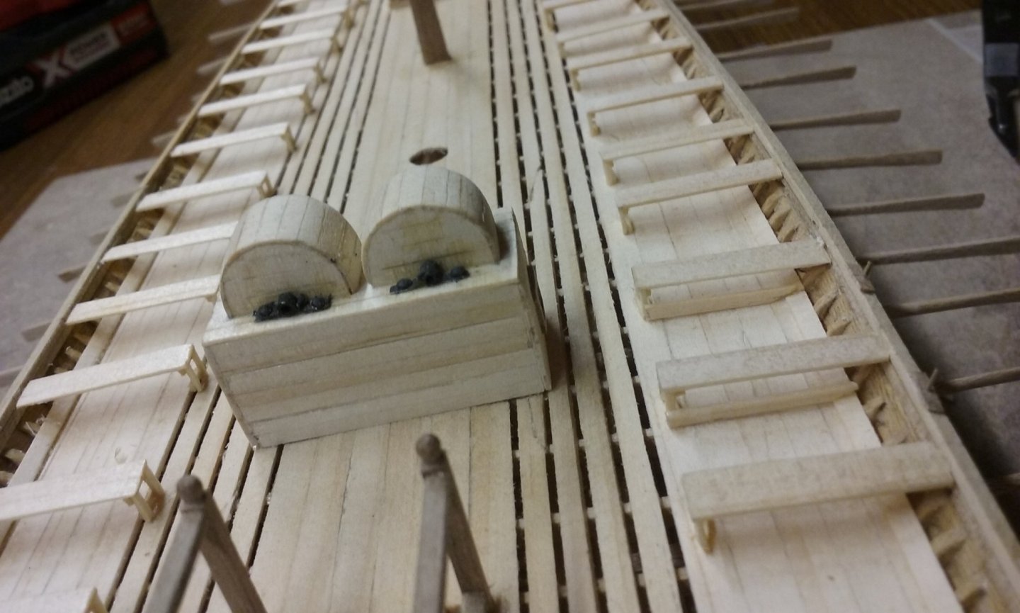
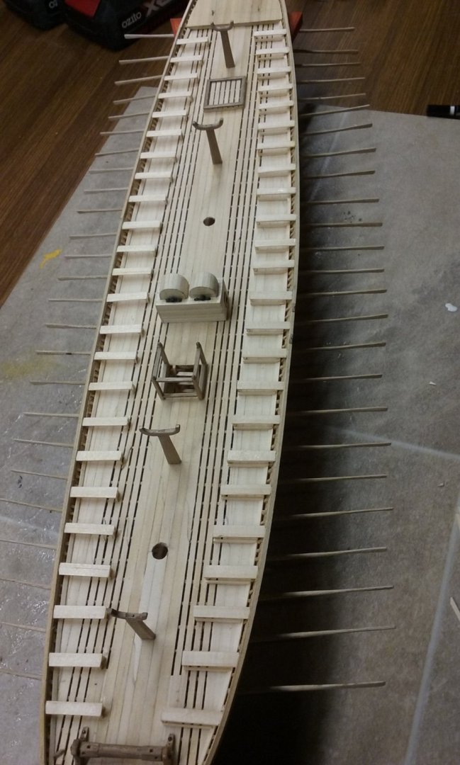
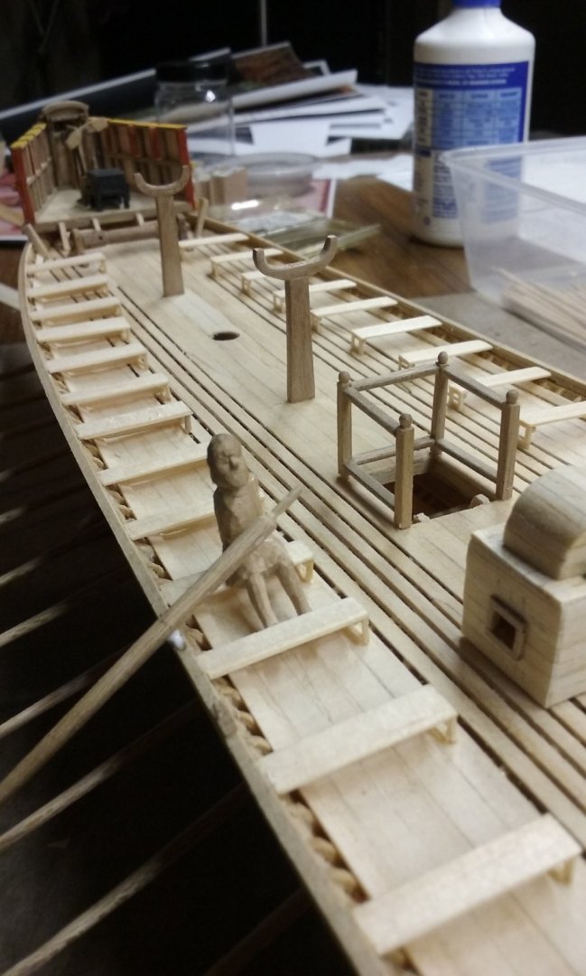
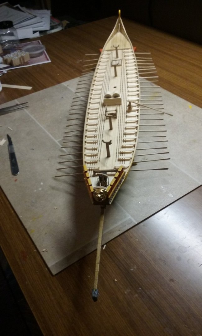
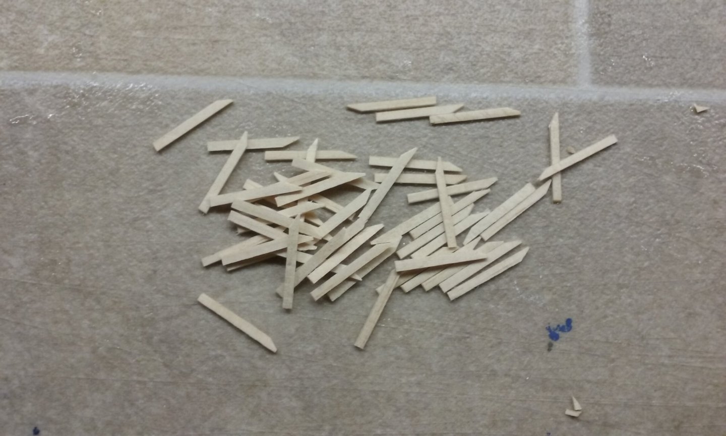
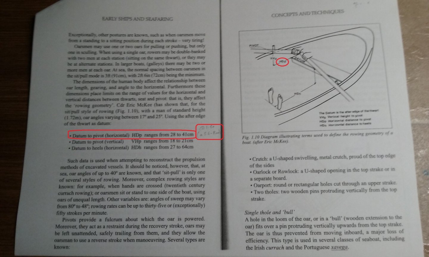
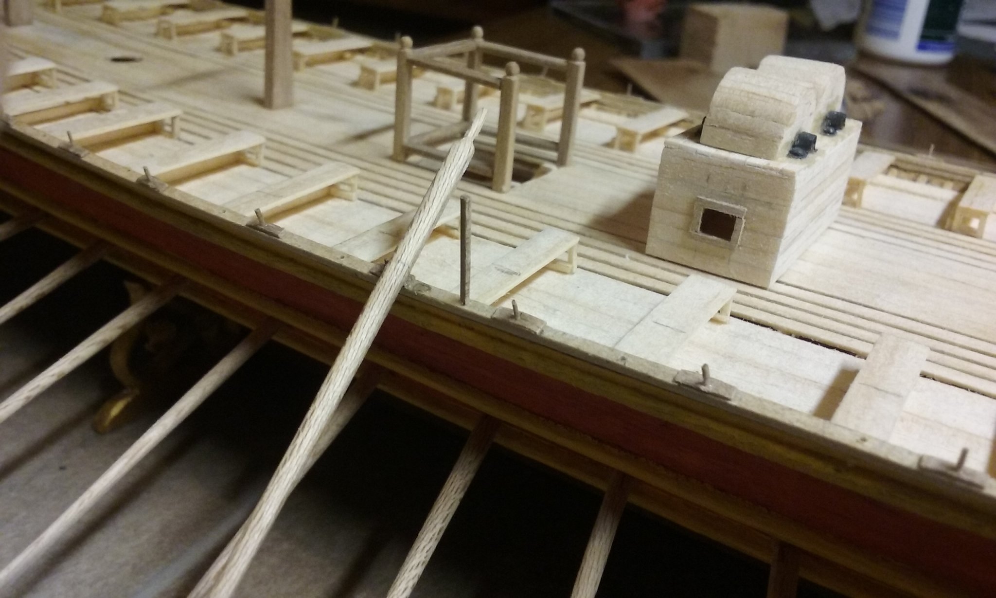
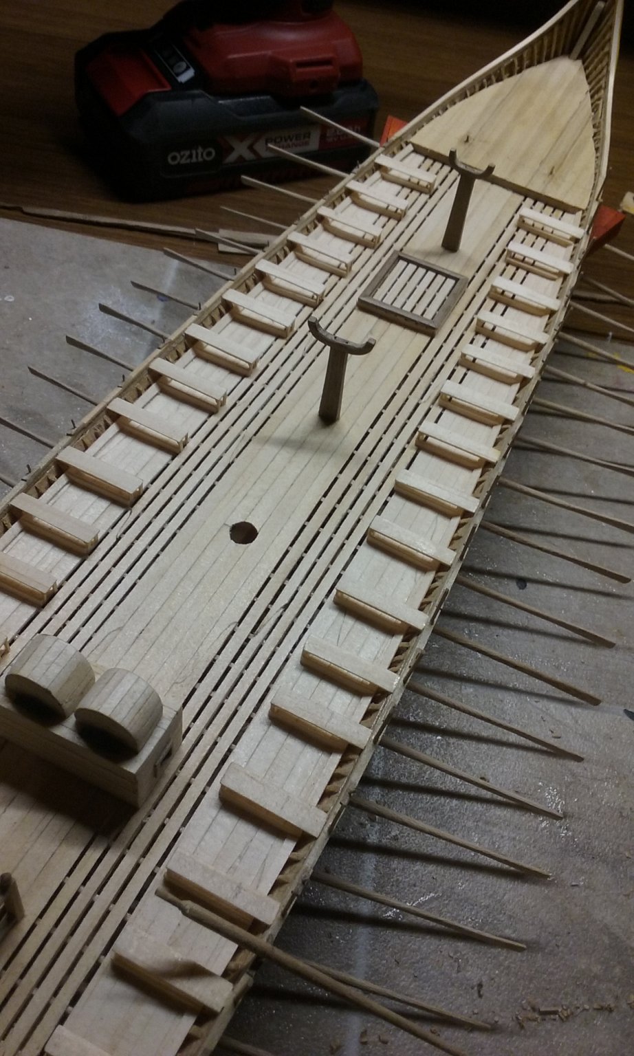
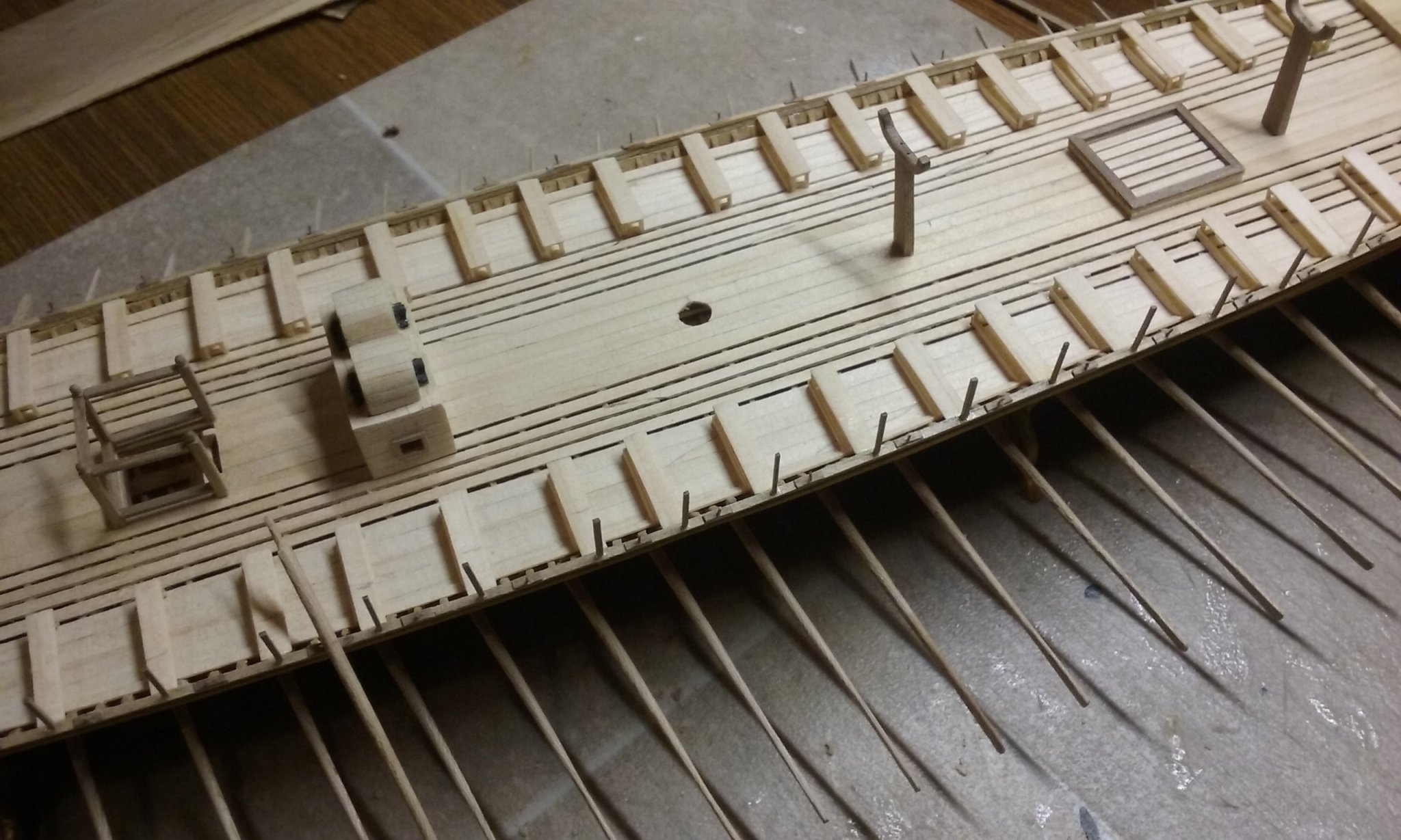
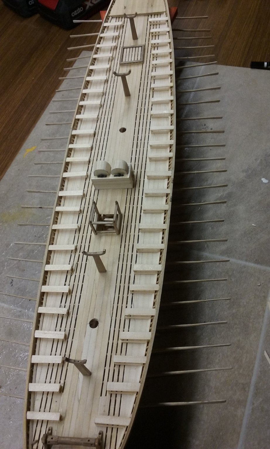
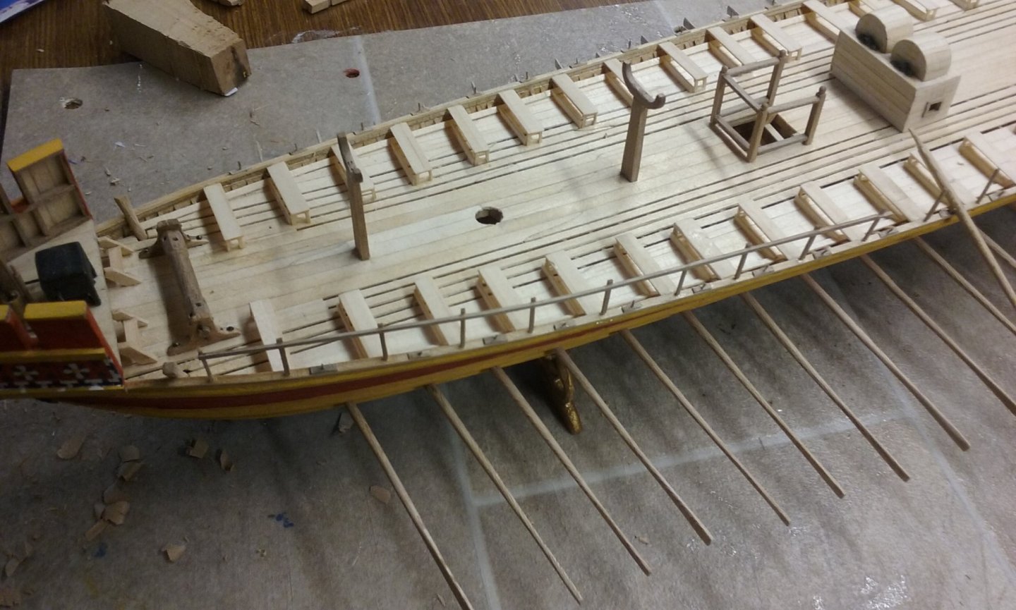
I've been busy. Here are the first steps in mass producing my oarsmen. This lot makes up just under half the number needed for the ship. Now I just have to carve them all . . . The book "Early Ships and Seafaring" by Sean McGrail contains a lot of interesting information, including the maximum and minimum distance for oared vessels (from archaeological finds) between the thole and the front of the oarbench. I tried one thole at the minimum distance (5.6 mm at 1:50 scale) and one at the maximum (8 mm ) to see how it all worked I've added the footrests at the back of each oarbench, for the oarsmen to push their feet against as they row. I cut strips from offcuts from deck planking etc. then cut them to length, trimmed the outboard end to follow the angle of the waterway and started gluing them in place. Here's one side complete (a bit hard to see - in the picture they're on the right hand side) I've put the first upper oar in (temporarily) to test which thole distance to use (turned out the minimum distance was best). Also to determine whether I've got the oarsmen right, and the correct configuration for their arms. Getting the upper oar at the same angle (from above) as the lower oars, (I used a block of wood as a spacer to get the oarblade at the right height) - as well as in a straight line between the oarsman's hands, the thole and the surface of the water. Looks like I still have some adjusting to do on the oarsmen's sitting position so their arms will be correct (compared to the photos I have of upper oarsmen on the trireme reconstruction Olympias). And here are the benches with all the footrests in place. Slow but steady progress. Steven