Louie da fly
-
Posts
7,990 -
Joined
-
Last visited
Content Type
Profiles
Forums
Gallery
Events
Everything posted by Louie da fly
-
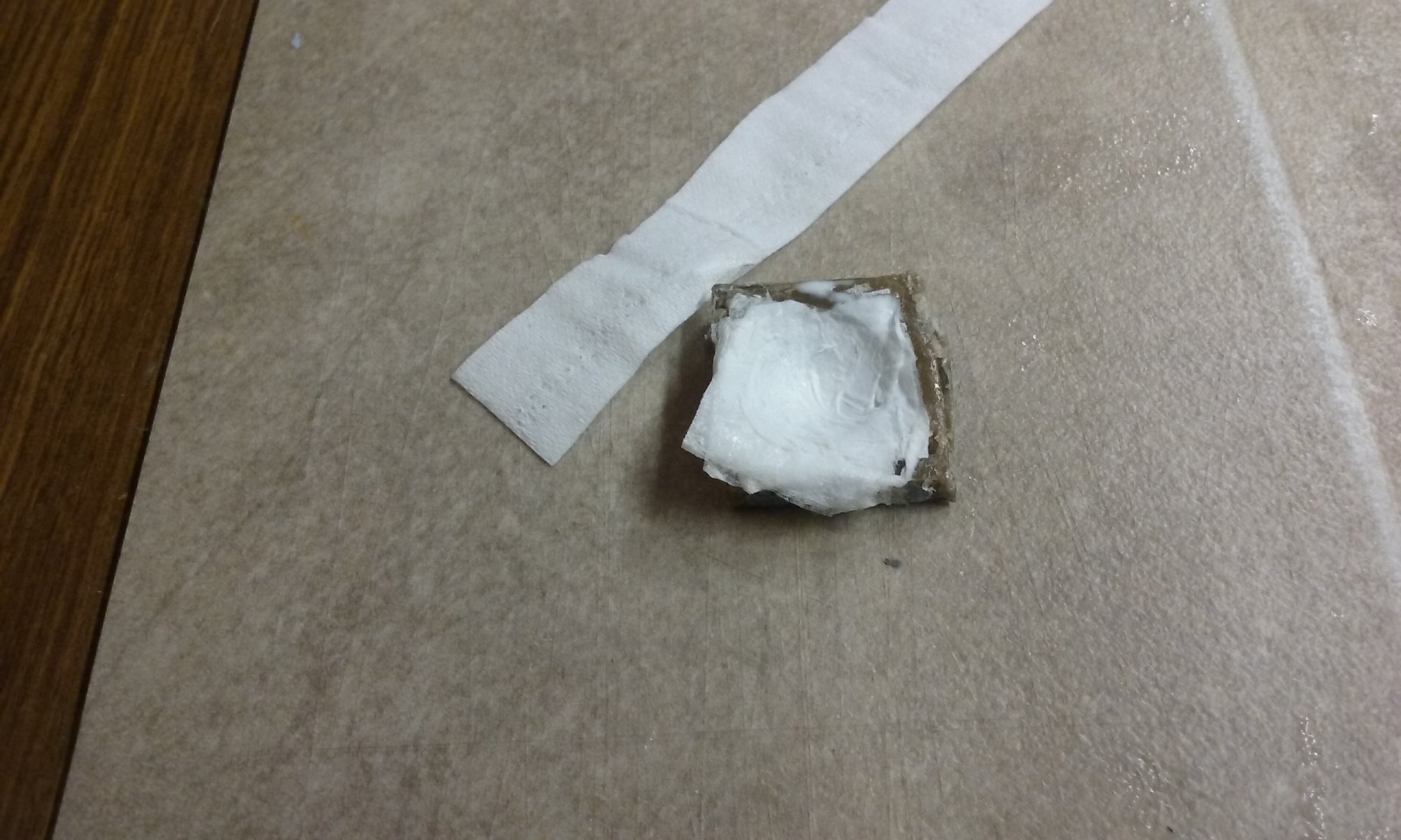
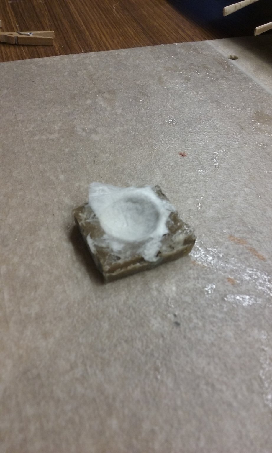
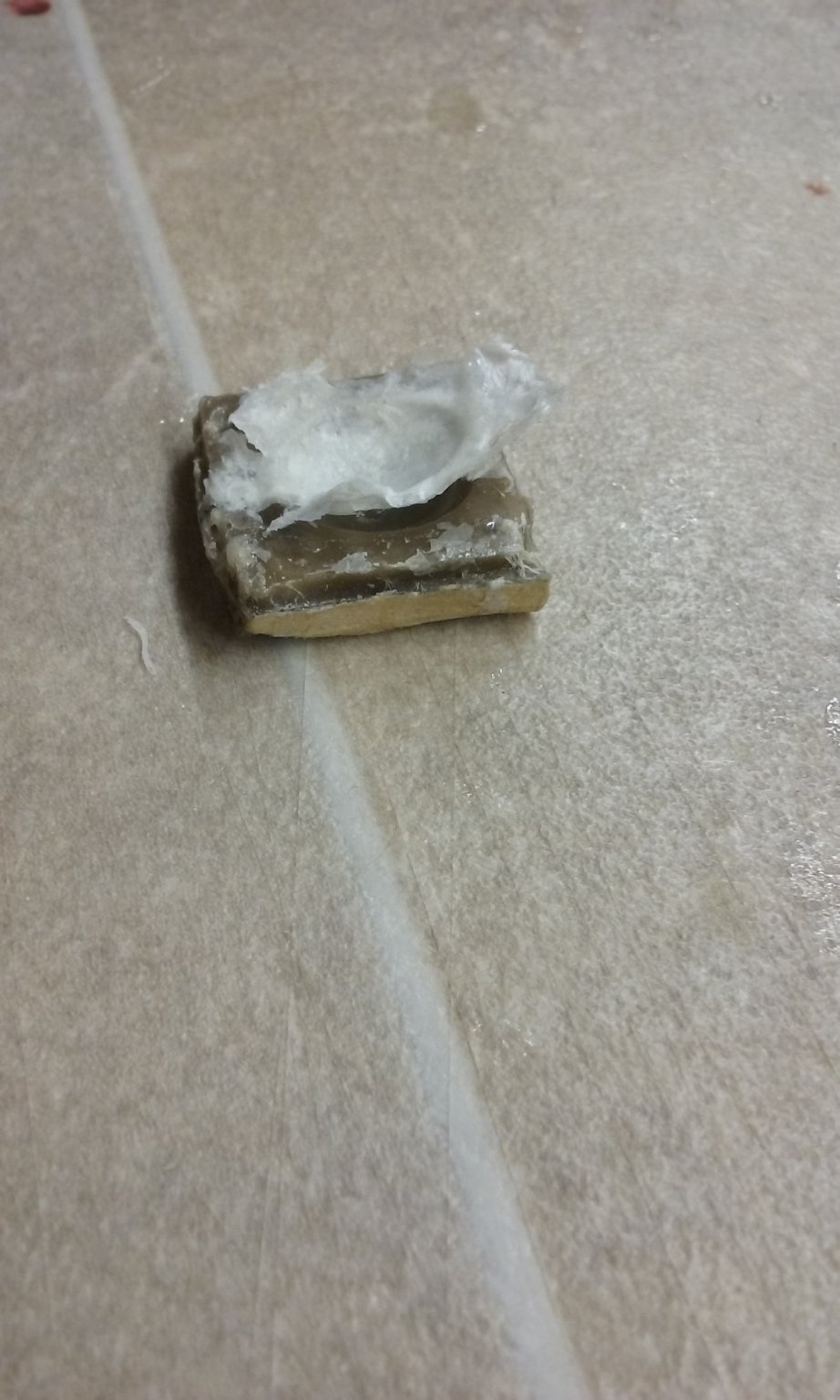
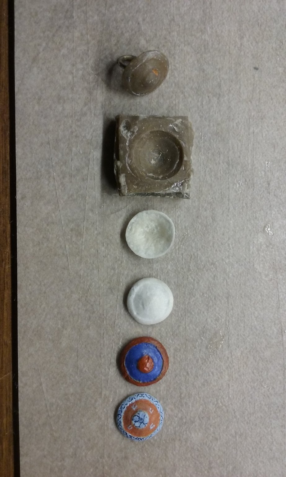
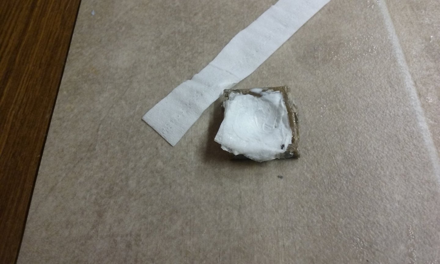
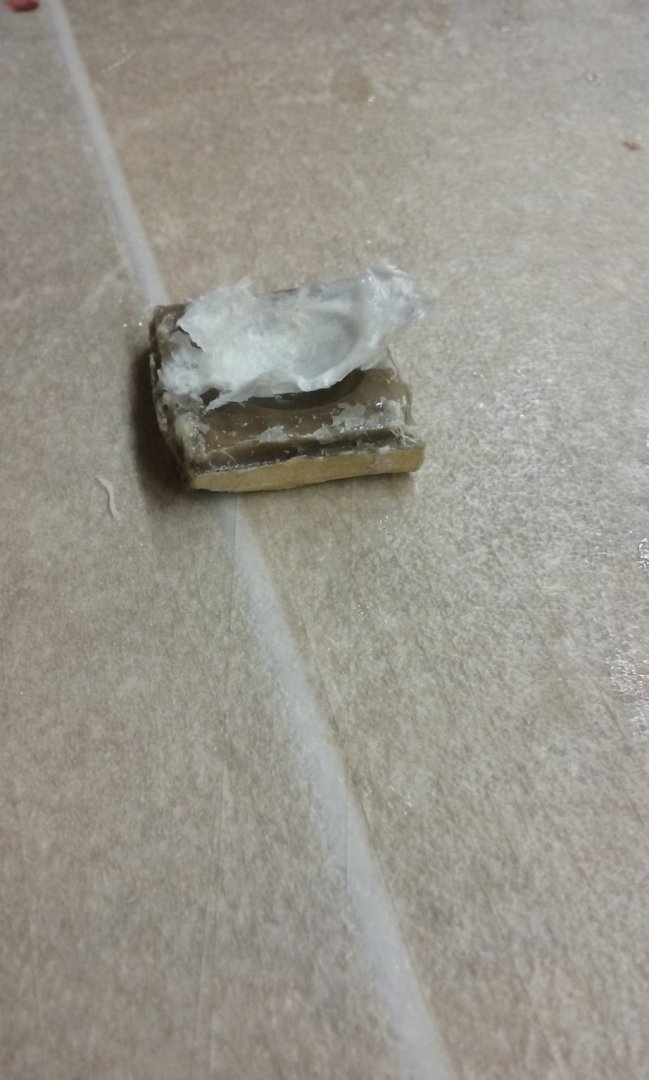
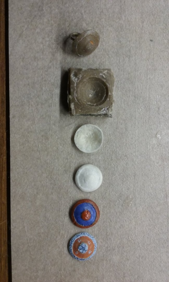
 Thanks for the likes and the comments. Mark, I started out with a "blank" (you know the original thing the mould is cast from -don't know the technical term) made of plasticiene (modeller's clay to those of you who led sheltered lives), then cast it in a little box filled with builder's bog (car filler) - brand name Plasti-bond. When it had set I coated the inside with something greasy so it wouldn't stick and cast the "male" part into it with more of the same stuff. I found you have to be careful to make sure you don't get little bubbles in the mould - though it can be repaired. Now I'm making the shields I find that smoothing with a finger is better than using the male half - it's more reliable and gets the detail better. I've always had a bit of a thing about the thickness of shields in model ships, having (in a previous life as a mediaeval re-enactor, prior to ship modelling) used a shield myself. Too thick and they get very heavy after a while - not a good thing when you're "fighting for your life". So I spent a lot of time and research trying to figure out how to make them really thin for the model. I tried wood, tinfoil pushed into the mould with a resin backing etc etc. The tissue/PVA technique seems to work best. Steven
 -
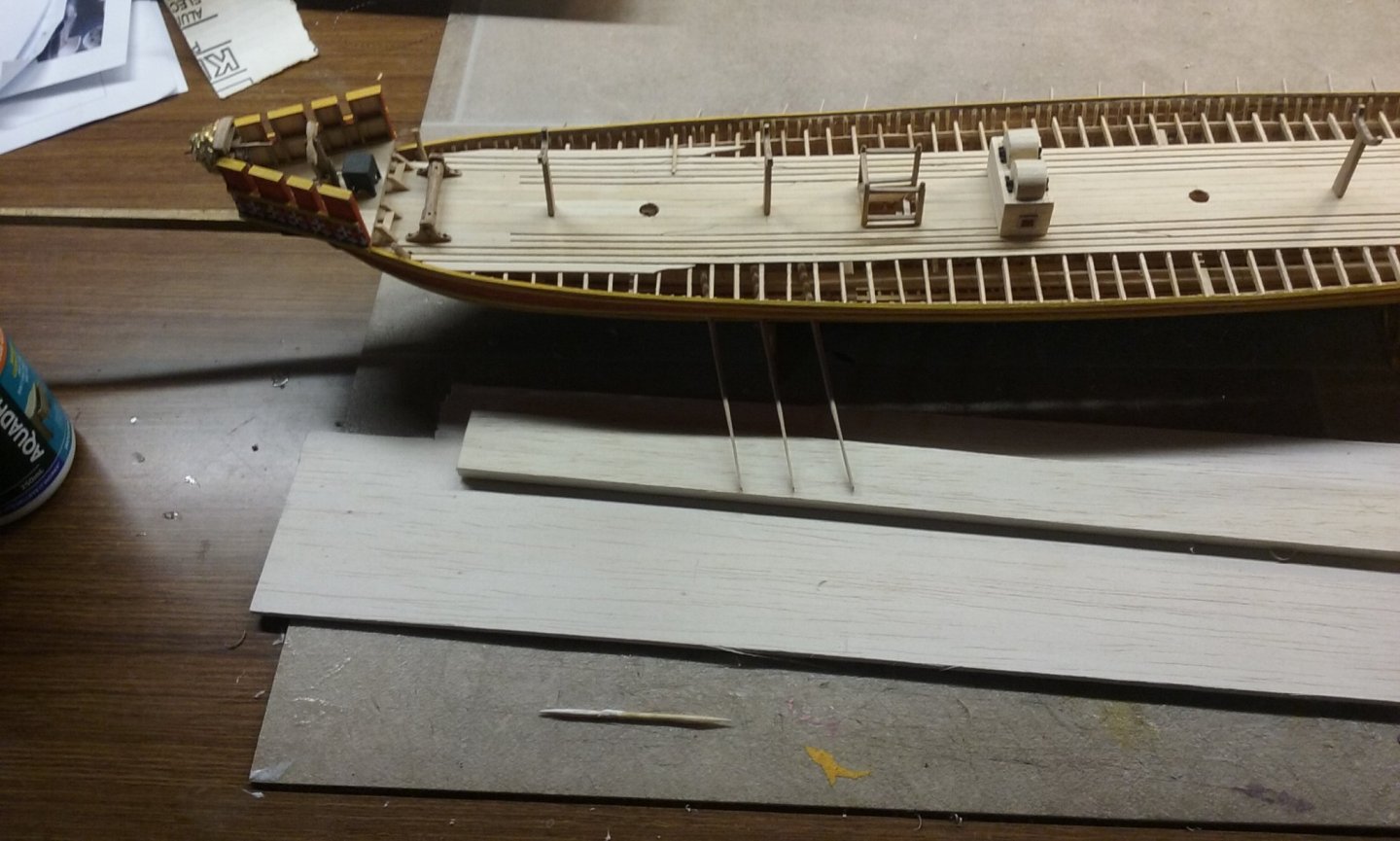
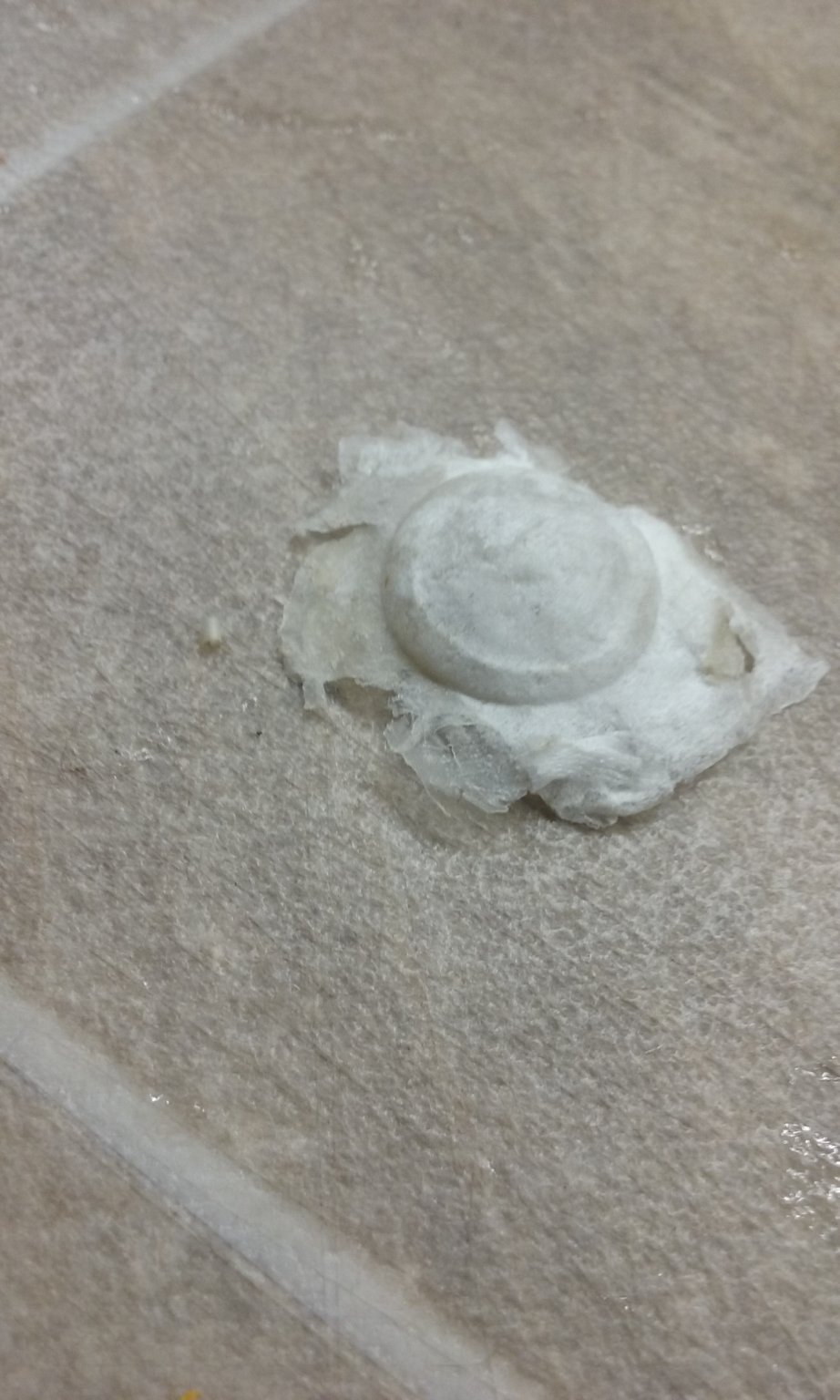
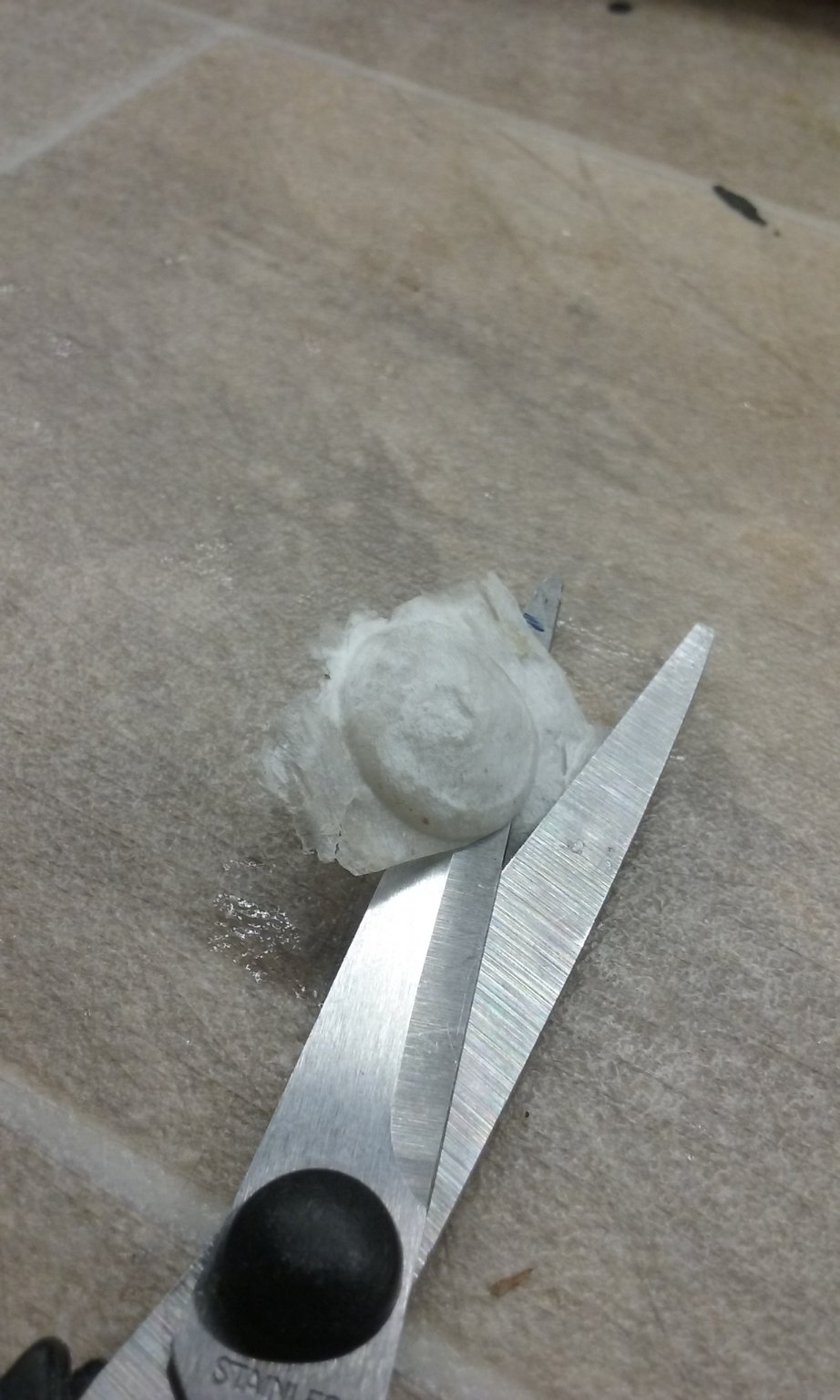
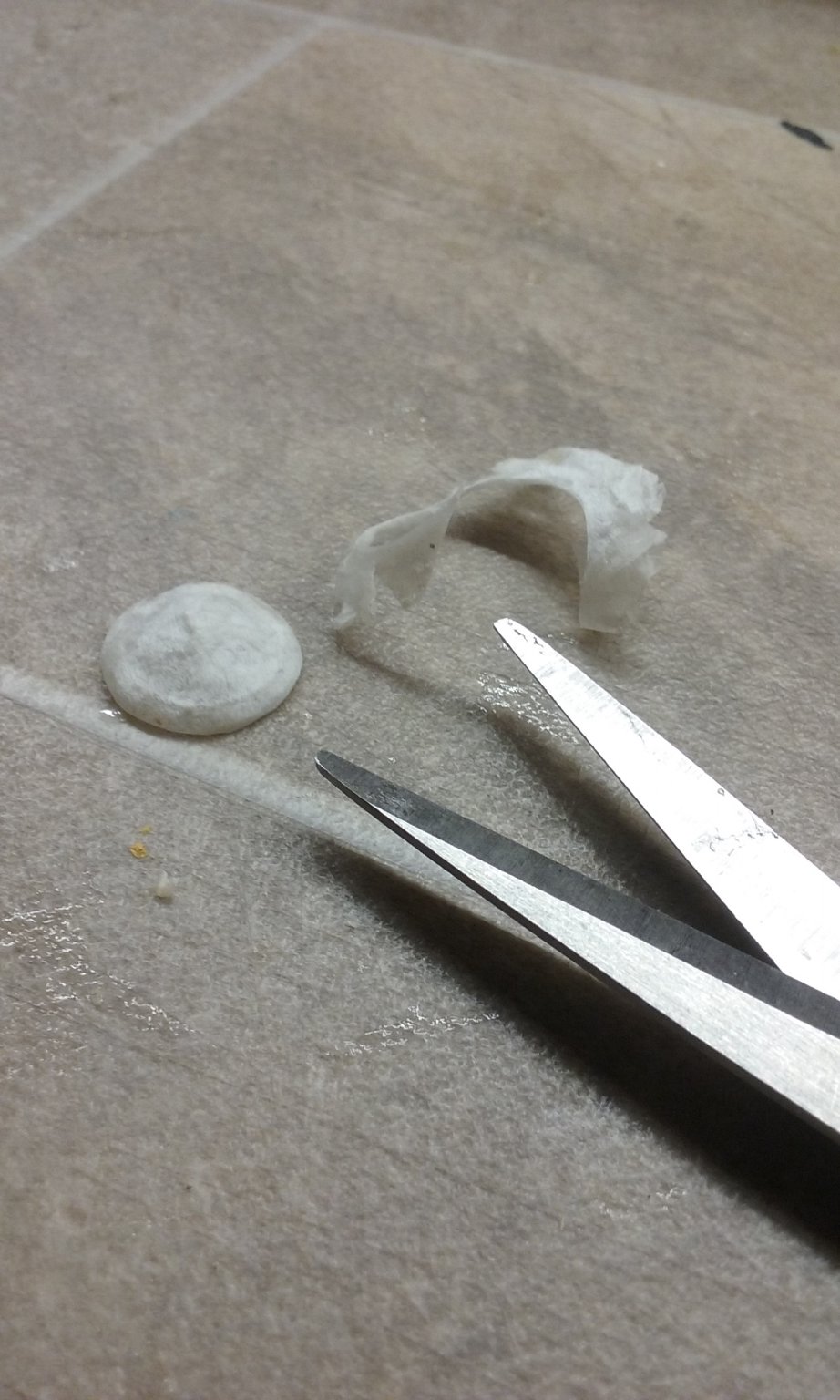
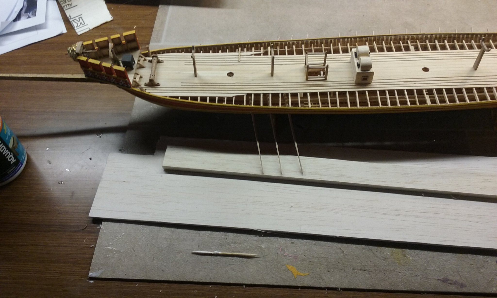
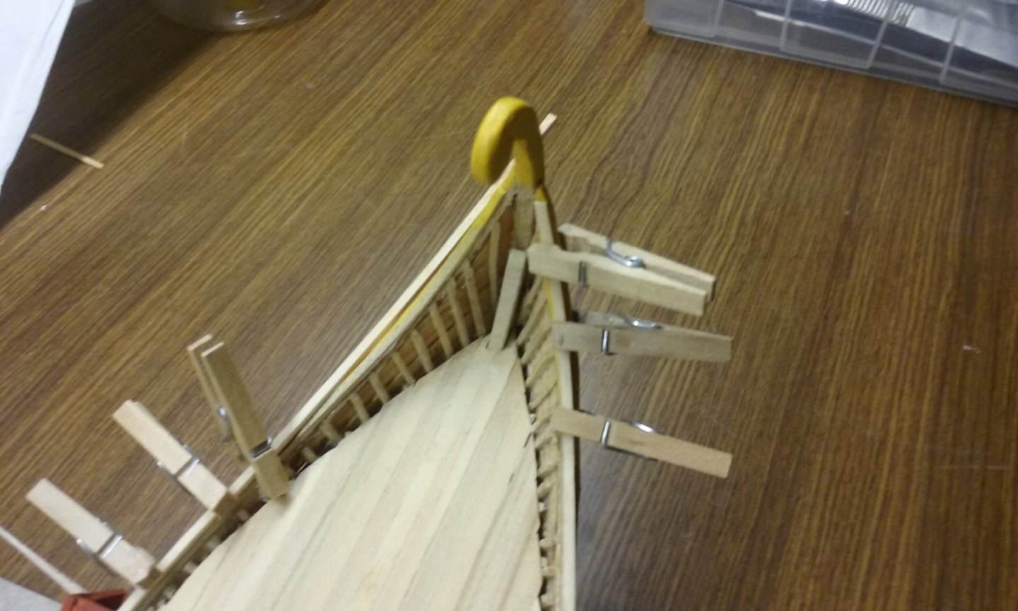
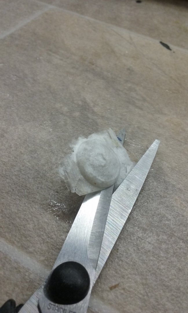
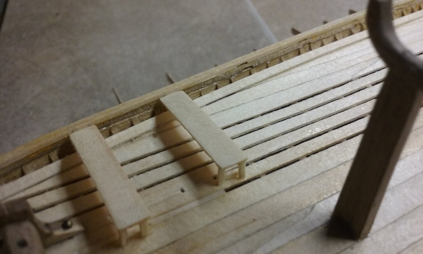
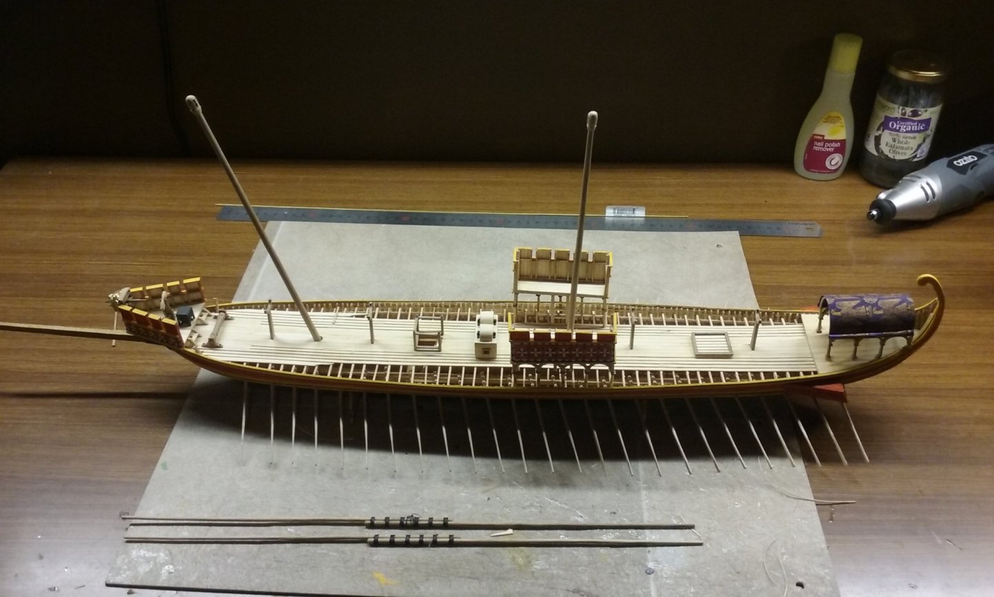
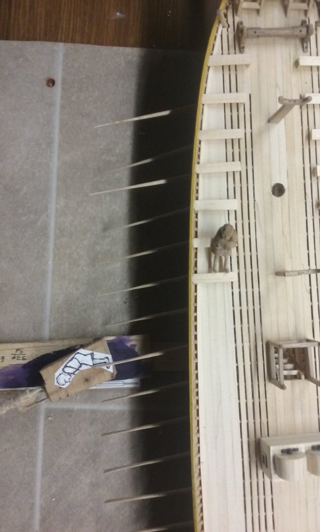
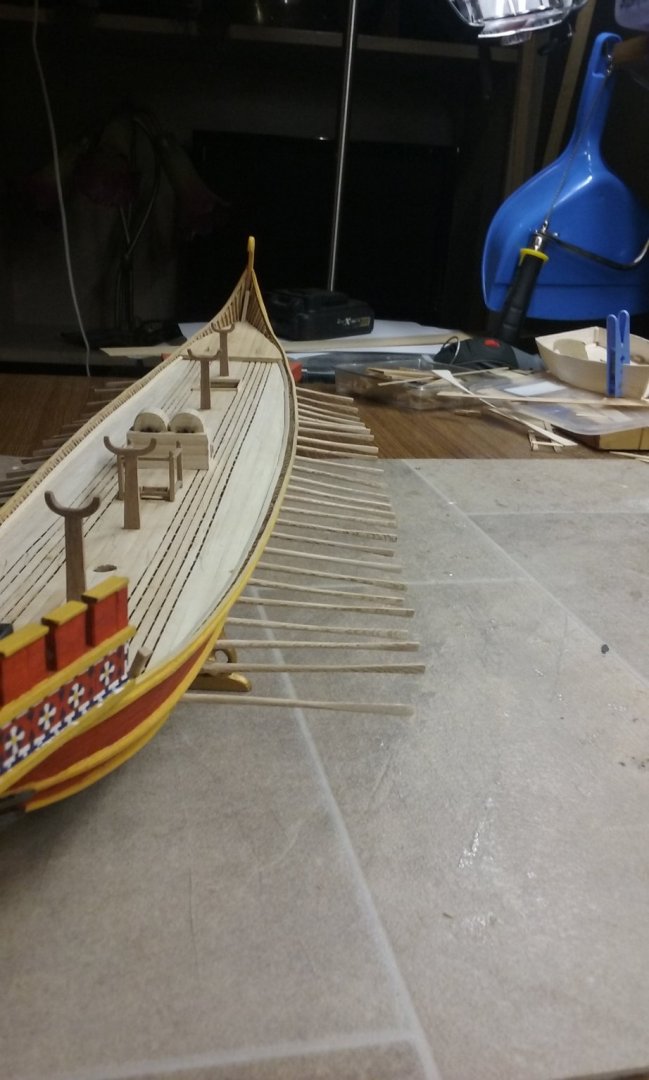
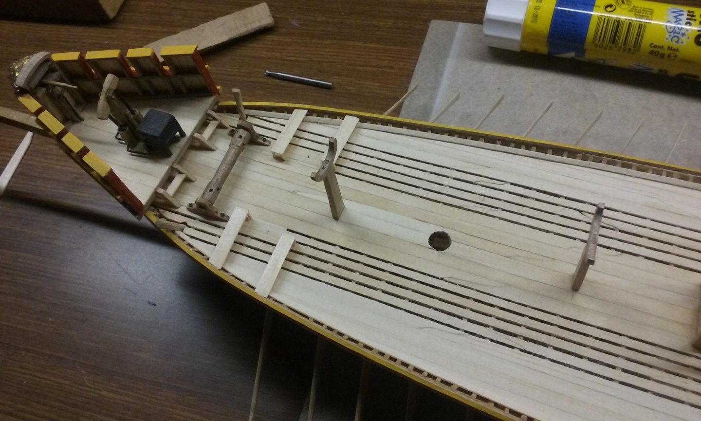
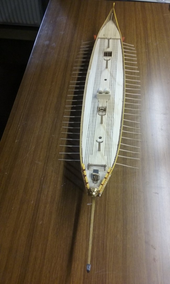
I've finished the "tail" stringer. And started on the oarbenches on the port side (note the cunning weight I'm using to hold them down). Just a little outline of how I make the shields from facial tissue. I first smear the inside of the mould with something greasy (I've been using butter - it's cheap and easily available) so the paper doesn't get stuck to the mould. I use a square piece cut from the tissue a little larger than the shield so it overlaps the mould, then put in a blob of PVA glue, then another square of tissue, another blob of PVA, until there are four layers in there (note each tissue is usually "4-ply" i.e. 4 layers of very thin paper, so I end up with probably 16 layers in all). One final blob of PVA, then I push it all down with a fingertip and smooth it around the inside of the mould. The more glue I have on my finger the less likely the paper is to follow my fingertip when I remove it. Leave it for several hours till the glue is almost set, the push down again with a fingertip, pushing the paper/glue matrix into all the corners of the mould so it takes up as much detail as possible. Leave to dry and then lift it carefully from the mould, then cut around the outside to get rid of the excess. Smear another blob of PVA onto the face of the completed shield - I find this improves the surface and gets rid of some of the smaller faults. Sand smooth with fine paper. Repeat 49 times. I use matt enamel paint (Revell or Humbrol) - I find it gives better results than acrylic - and a very fine watercolour brush. Steven


-
Never heard this one - I love it! English is so full of irregular words that don't follow the rules you'd expect them to. I'd hate to have to learn it as a second language. And if we say "I write, I wrote, I have written" - shouldn't we say "I bite, I bote, I have bitten"? And we have "one horse, two horses" and "one duck, two ducks" but "goose" becomes "geese" and the plural of "sheep" and "fish" is "sheep" and "fish" But even among native English speakers there are regional variations. It still pulls me up sharply to see someone from the US (I don't know if this applies to Canada as well) write "If I would have thought ahead I would have done a better job" - where I come from it's "If I had thought ahead I would have done a better job". English is such a mish-mash of other languages it's full of confusion and special cases. Digression welcome! Steven
-
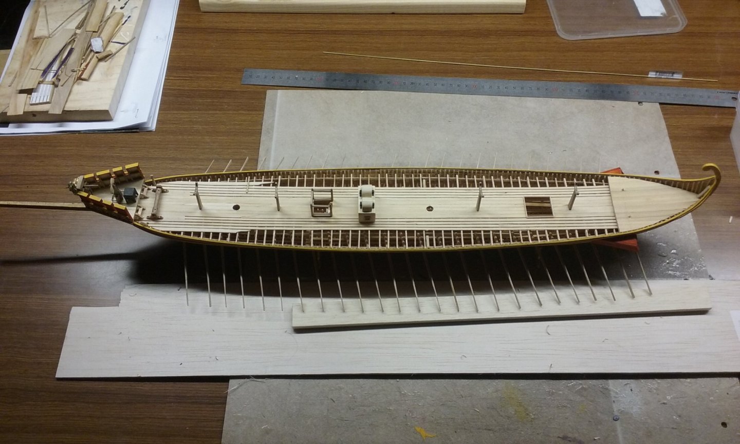
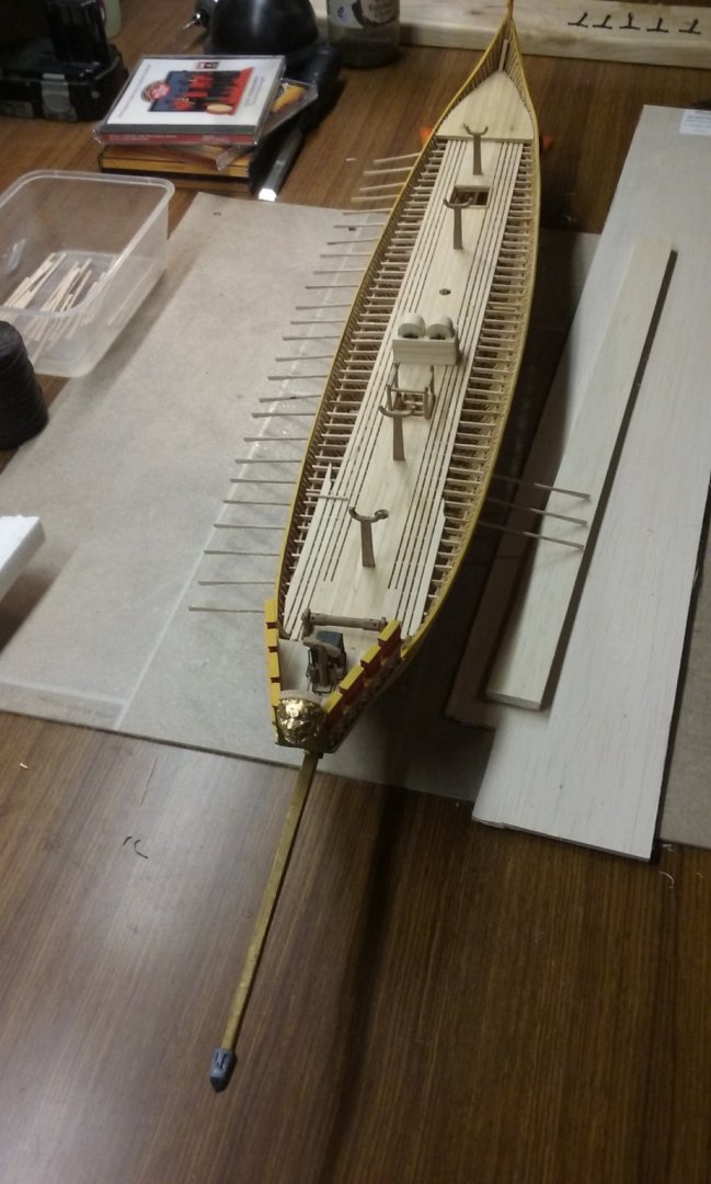
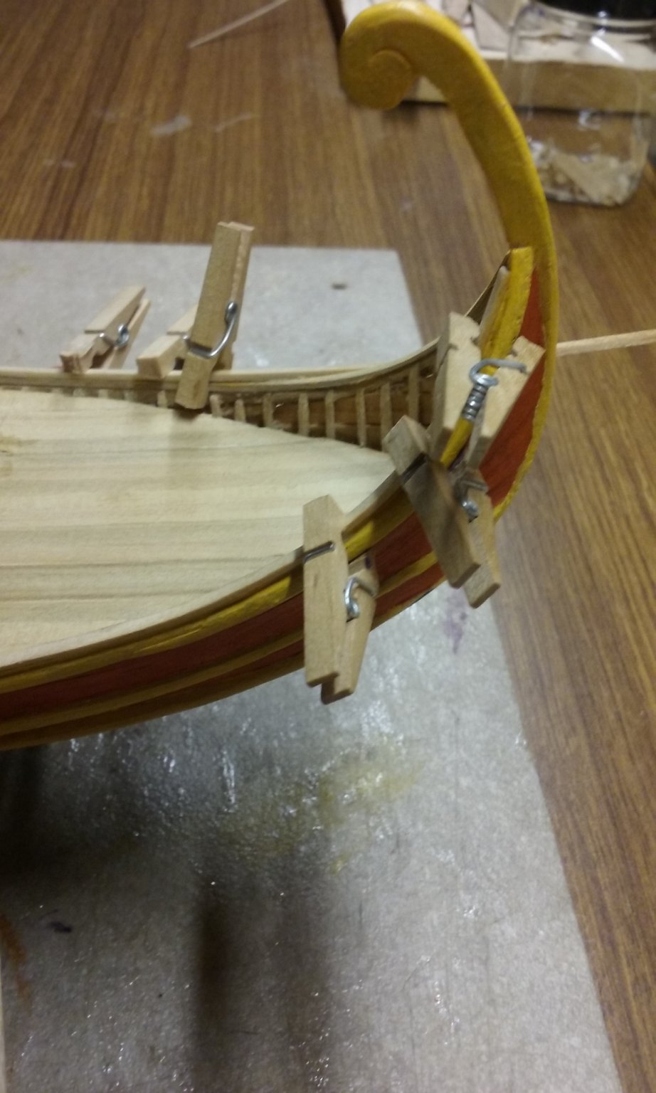
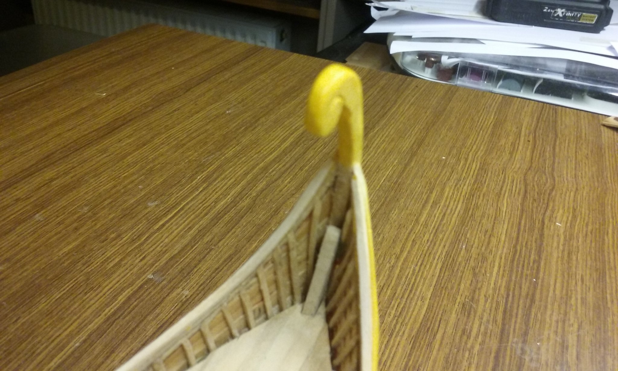
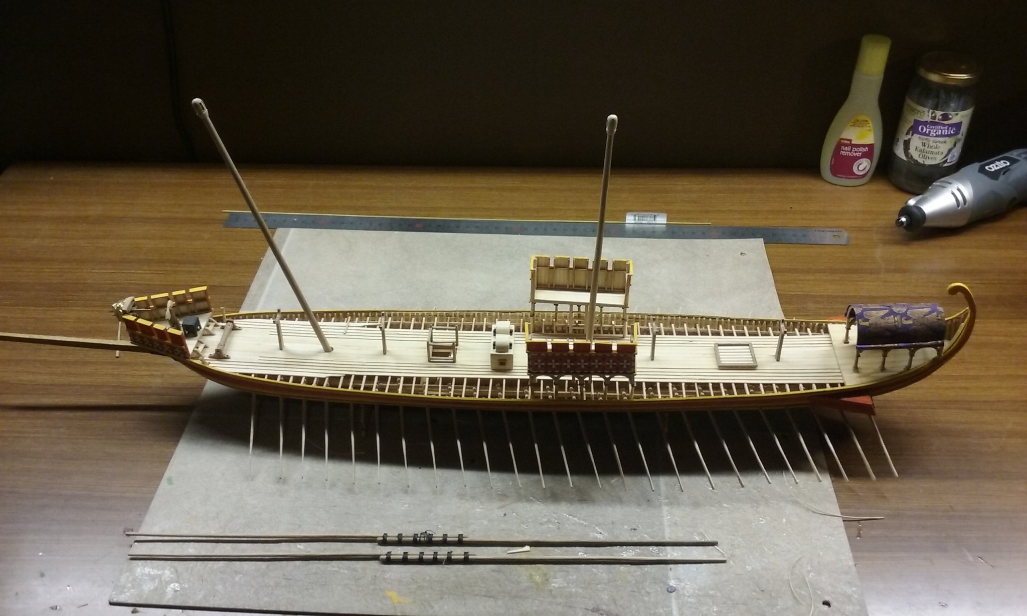
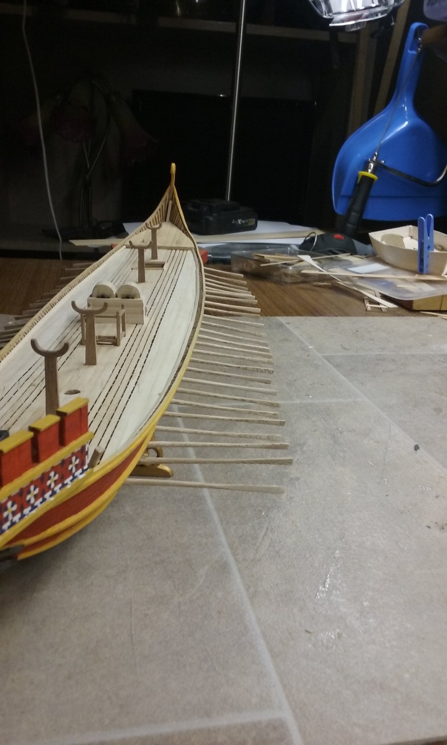
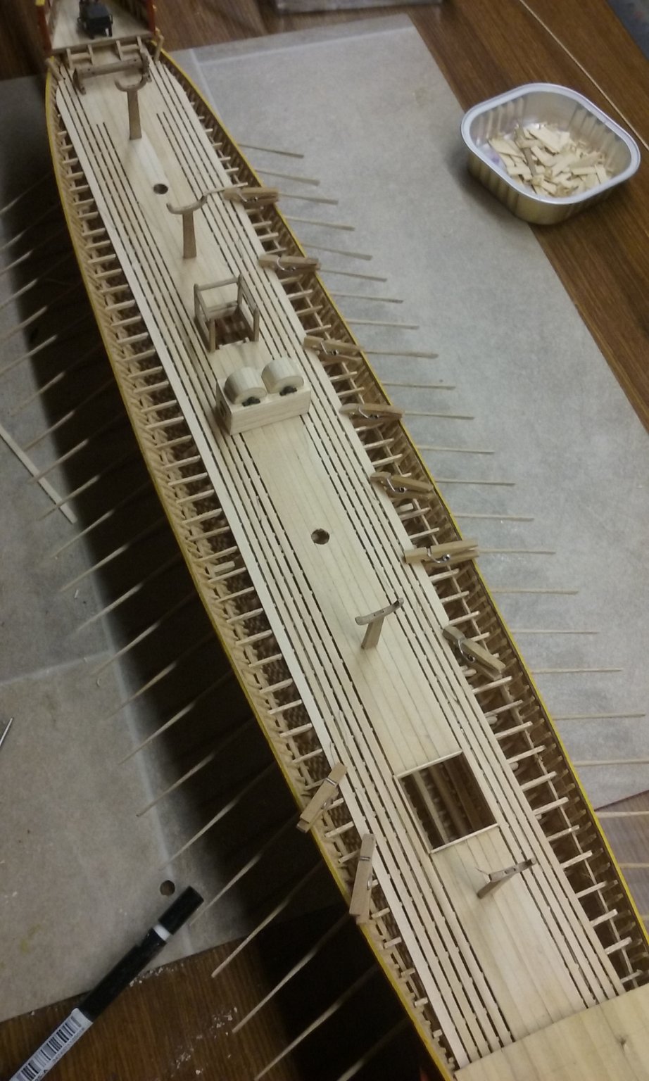
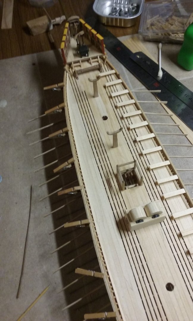
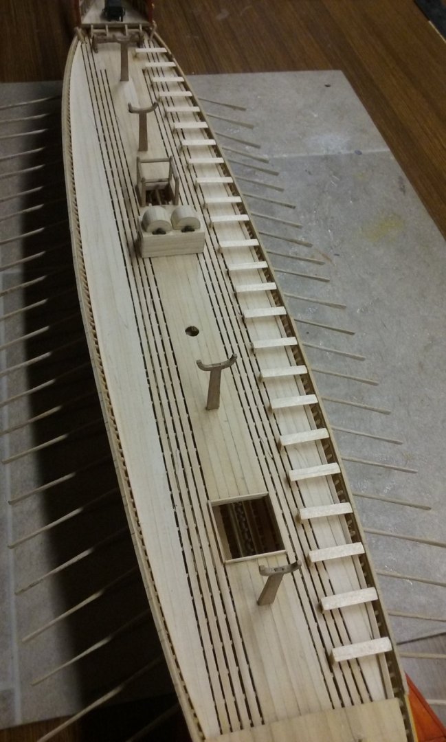
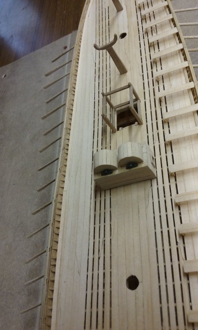
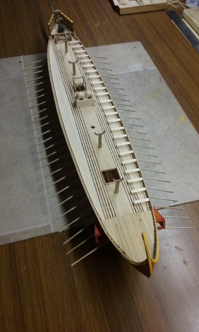
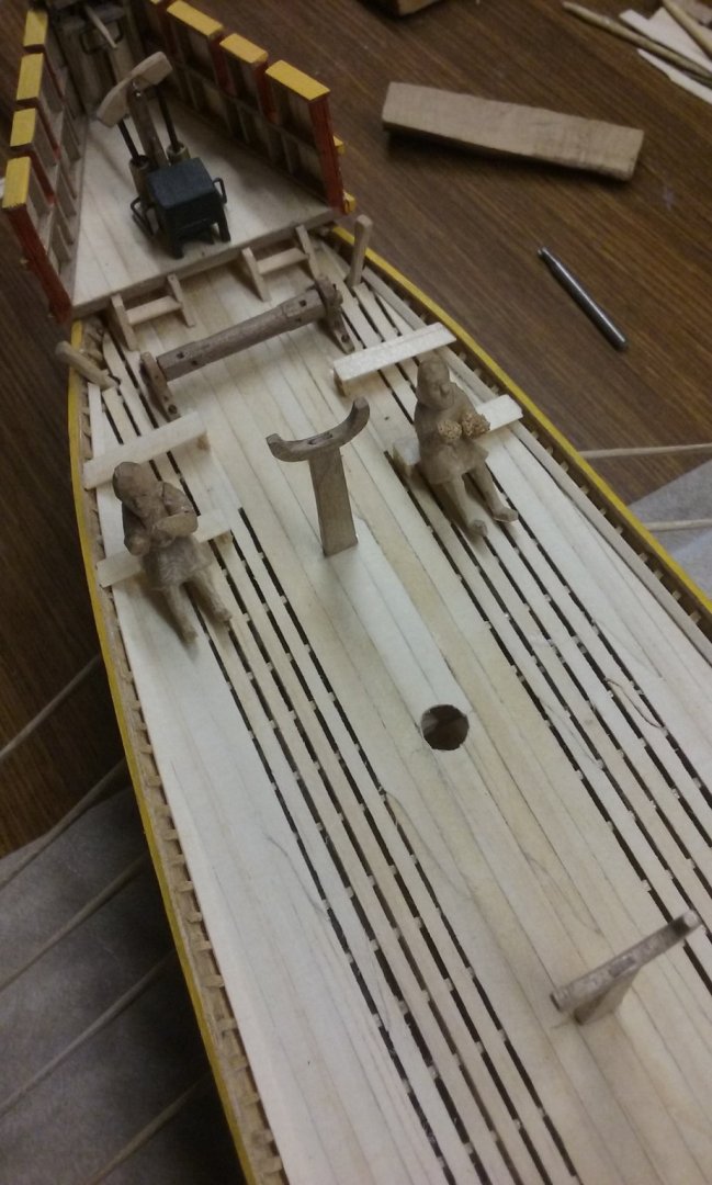
Thanks everybody for all the likes. I've added all the benches for the starboard side and lined up the slots for the benches in the port stringer and glued it on Here are the benches for the port side ready for gluing into place. And I've scarphed on the "tail" extensions for the stringers. Once the glue is dry I'll start curving them to fit the curve of the tail. Quiet awhile ago I did a lot of experimenting on how best to make the shields for the pavesade - the row of shields along the side of the ship to protect the upper oarsmen, bearing in mind that real shields were pretty darned thin (usually between 7 and 10mm = about quarter to half an inch), which scales at 1/7 to 1/5 of a millimeter (= about 6 to 10 thousandths of an inch if my maths is correct) Turns out tissues (as in blowing your nose!) are the best material for this job. I made a mould out of builder's bog, put in layers of tissue glued together with (quite a lot of) PVA (white) glue and squoze (is that a word?) the resultant paper/glue gunge between the male and female halves of the mould. Once dry I had to trim each shield to shape, then sand to get a reasonably smooth surface for painting. I've done about 5 so far - another 45 or so to go. I've put a lot of research into the shield "devices" (decoration) used by the Byzantines, and once I've made the rest of the shields I'll be able to paint them with accurate designs, though I'm mixing and matching the colours to a certain extent (within the colour palette I know the Byzantines to have used). Steven


-
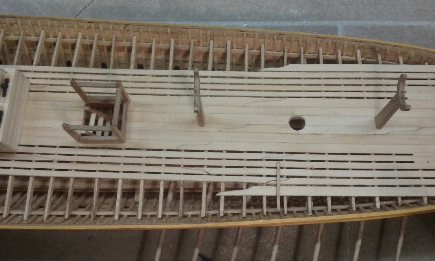
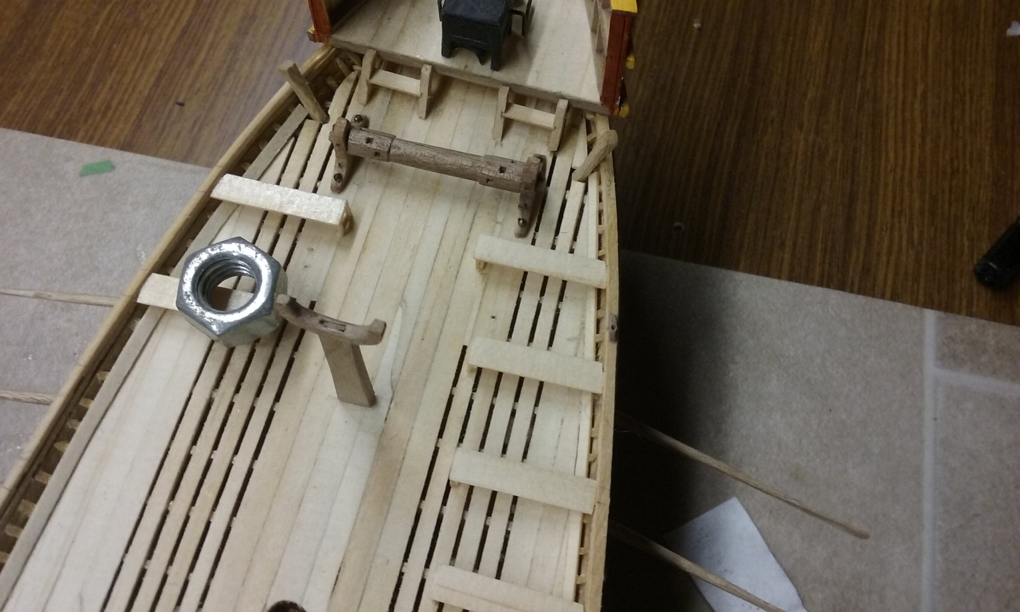
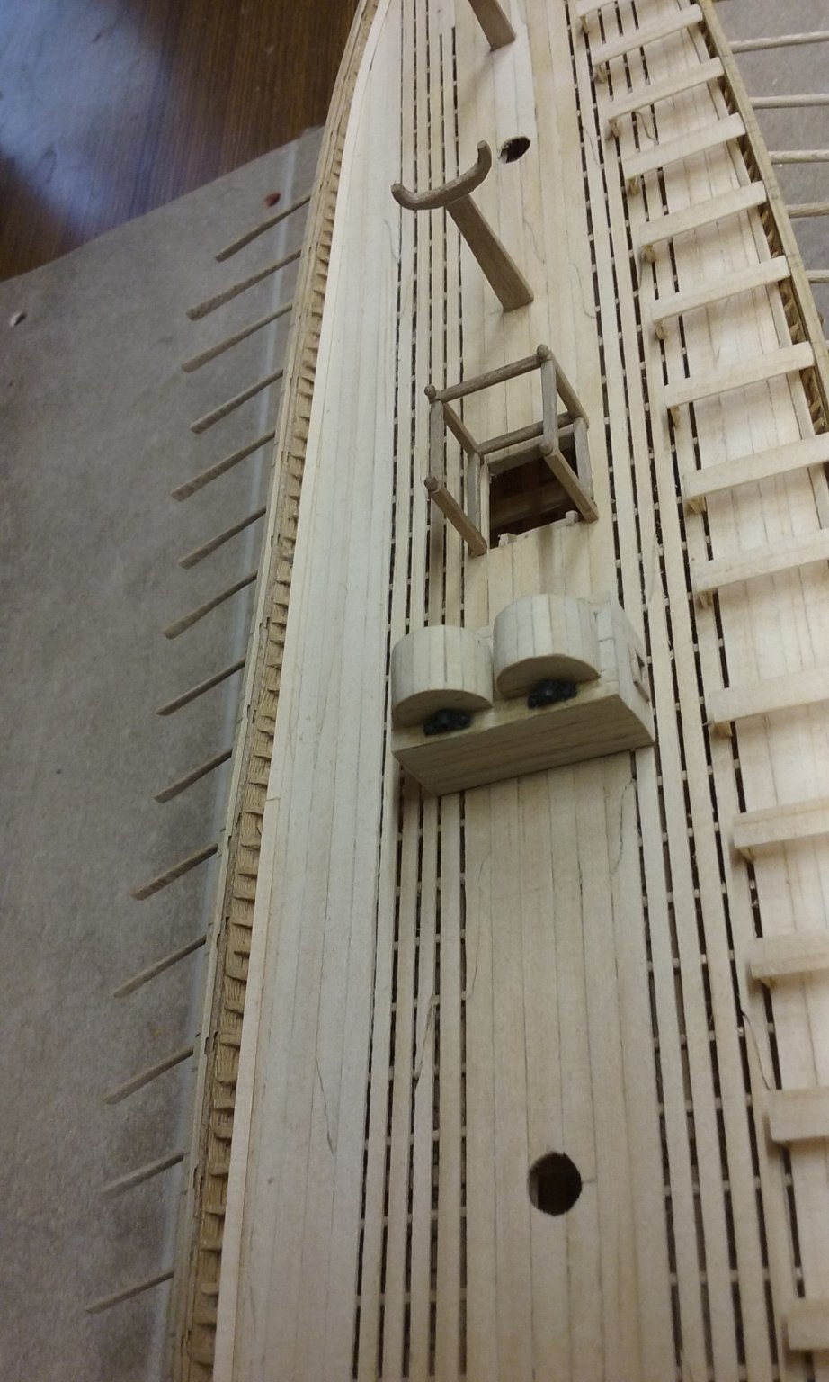
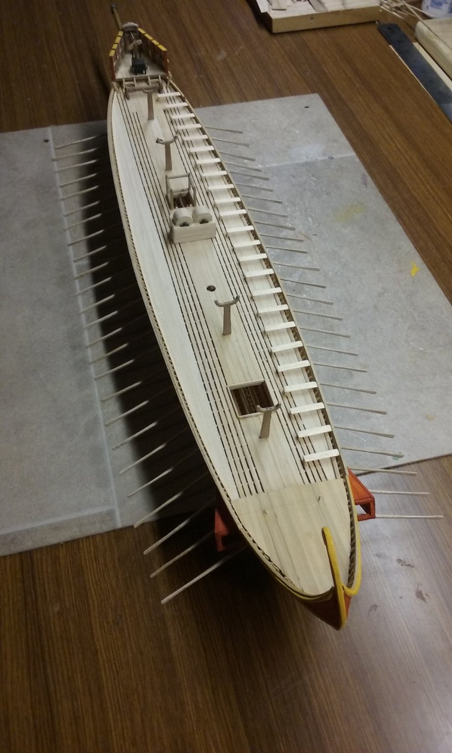
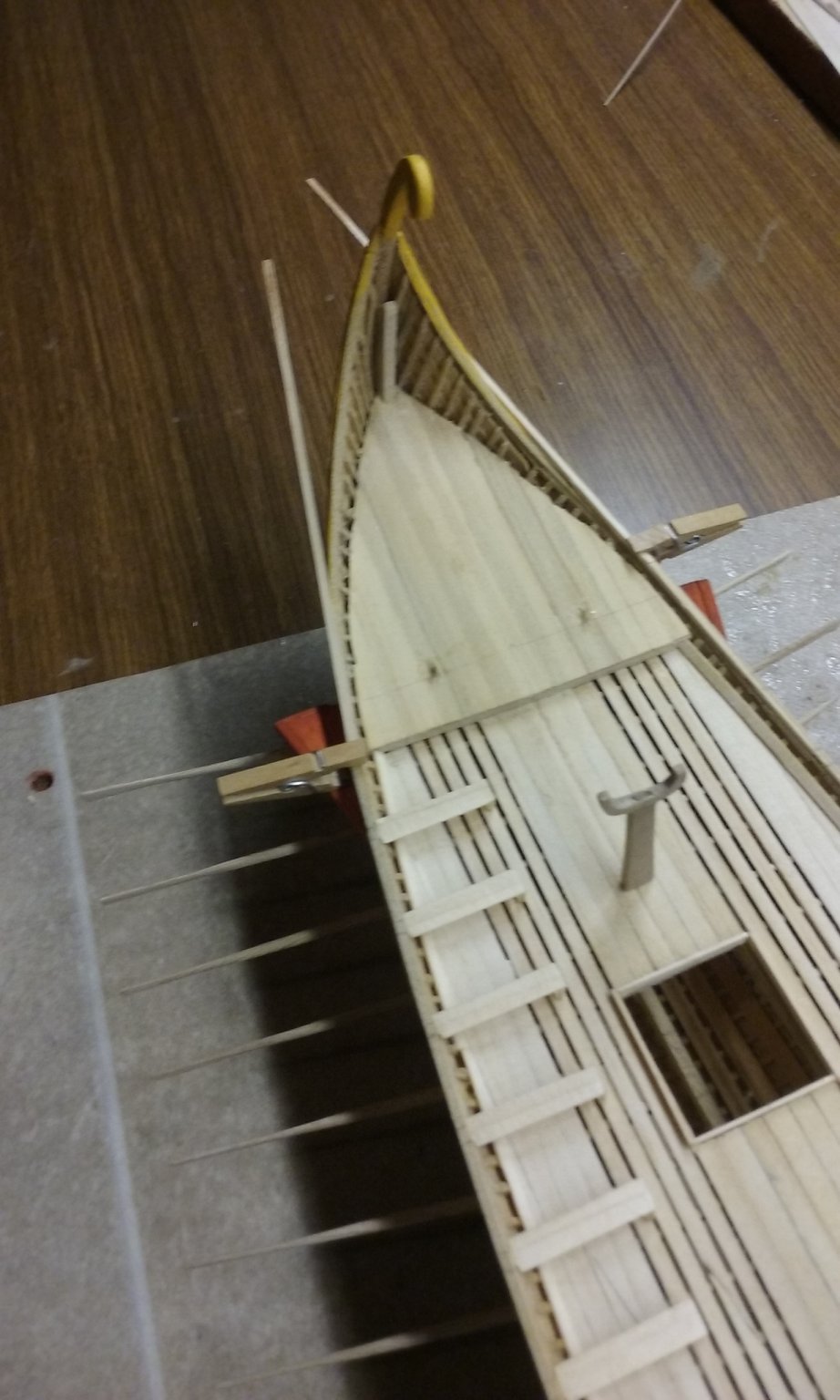
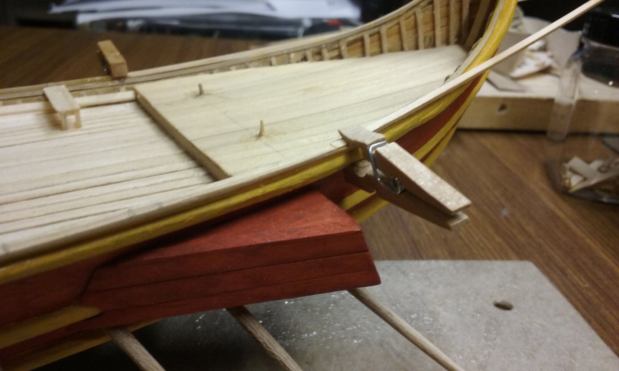
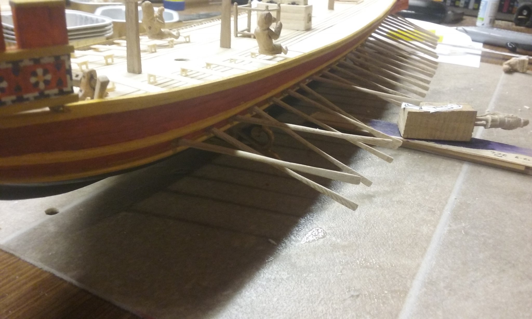
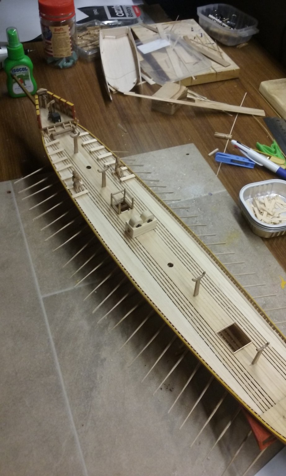
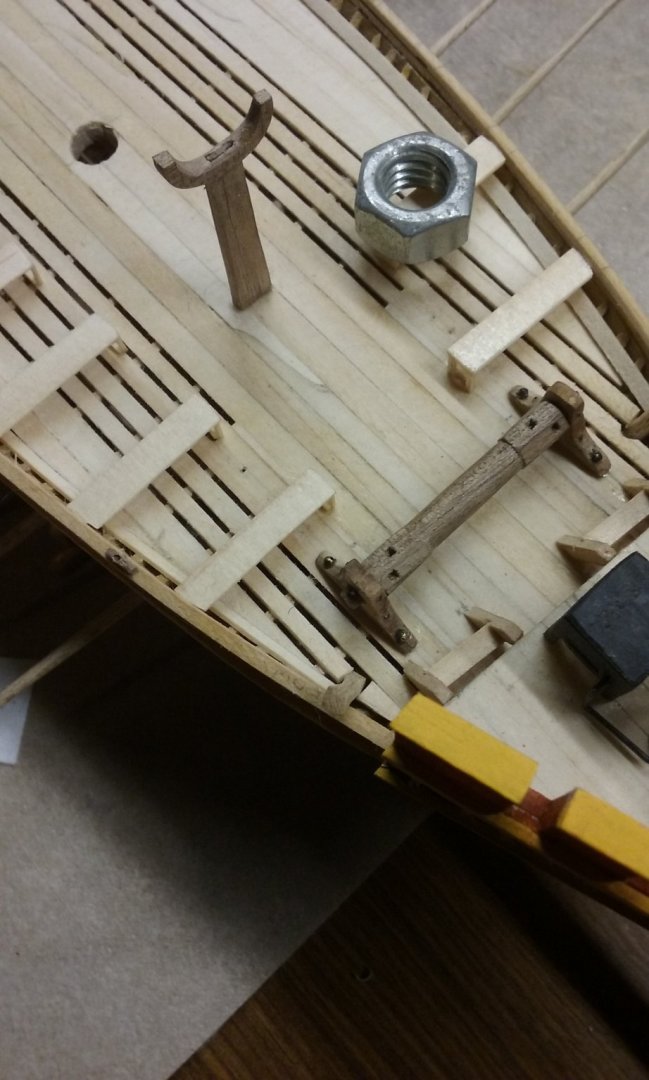
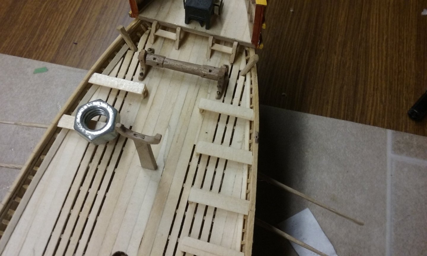
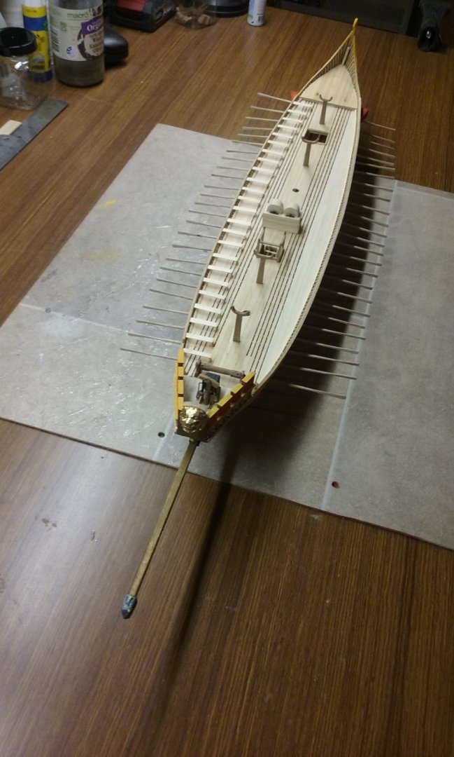
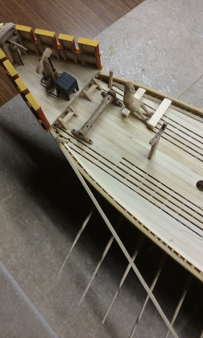
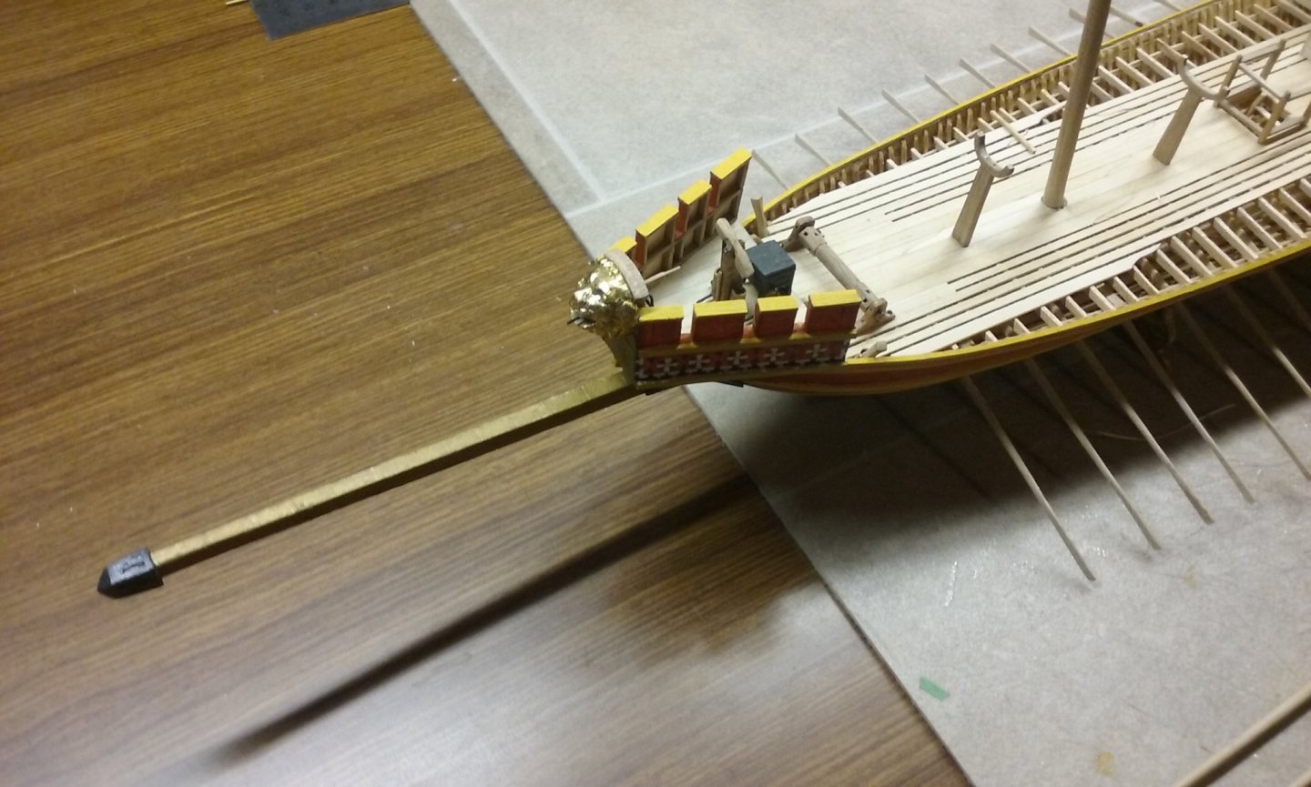
Hmm, dunno. I hadn't thought about it, but certainly a nice rectangular hole like that doesn't seem suited to a round bit of rope. Next step in construction: One of the Yenikapi galley finds had slots in the wale to take the ends of the oarbenches. In line with that I'd made similar slots for the upper oarsmen's benches, but as I'd already discovered the upper wale was too low for them I added a stringer on top of it to take the slots. While making the oarsmen it was necessary to get the correct relationship between the gunwale (the pivot point of the oars) and the water level (where the oarblades reach to) and the level of the oarsmen's hands; they all have to be in a straight line. Unfortunately, I discovered that even with the new stringer the slots were too low, so either the oarblades would be too low or the oars wouldn't sit on the gunwale or the oarsman's hands would be too high. And anyway as it was the benches would be only about 200mm (10") above the deck - Though an oarbench doesn't need to be as high as a normal chair - and in fact shouldn't be, because it makes the centre of gravity too high - they shouldn't be that low. So I had to raise the notches so the benches would be higher. I decided to add yet another stringer on top of the first one, smoothed off to look like it's part of it, with new slots to get the benches high enough up for the oarsmen to sit properly. Here's the starboard one under way. I just carved the slots in the underside of the stringer, as the lower stringer would act as the underside of the slot (the photo below shows the stringer from underneath - the diagonal beams are the oars). Here is the port side stringer with one end glued in place, ready to bend round on top of the lower stringer. And the first two starboard benches in place with an oarsman sitting on one. 'E looks 'armless . . . (I'm still working on the exact configuration of the oarsmen's arms to get everything to line up). After I'd added the starboard stringer I found that some of the slots didn't line up with the ones below them, and I was in the process of ungluing the rotten thing and starting again, when I realised the two slots nearest the bow actually did line up, and the ones on the new stringer were actually better located than the lower ones. So I left it. Then I had the problem of what to do with the lower slots. Fill them up so they couldn't be seen? But as it turns out the oarbenches conceal the lower slots so I don't really have to do anything to them at all. My next step is to get all the starboard benches in place, then I can draw lines across the breadth of the ship at each bench to make sure the port benches line up with the starboard ones - something I hadn't thought of when I started putting the benches in place last time. Steven


-
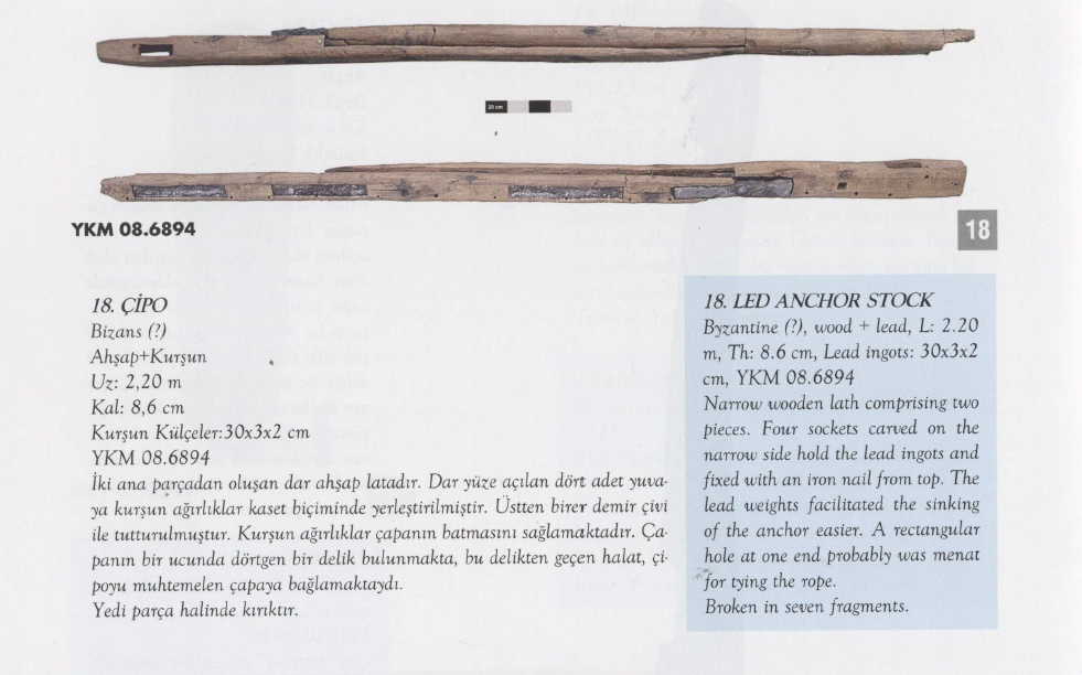
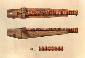
Returning for a moment to the discussion of using an anchor chain to weigh down the head of the anchor so it would "bite" better, I'd forgotten I had this: It's from the Proceedings of the First Symposium on the Marmaray-Metro (Istanbul) excavations May 2008. Obviously from this the Byzantines were awake to the problem, but had their own solution to it - lead weights inserted into the anchor stock! Steven
-
Hmm, you're right. Even the best rowers show a certain amount of variation. Look at 3.57 and 11.00 at On close inspection, I do see a certain amount of variation; even a suggestion of the occasional crab being caught. 8.19 doesn't count - they're just getting back into their stroke after not rowing on one side, to allow the ship to turn. (I wonder how tightly she could turn if one side backwatered!) Thanks everybody for all the likes and the encouraging comments. Steven
-
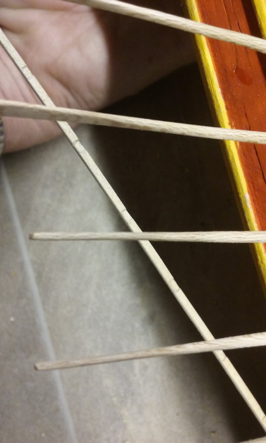
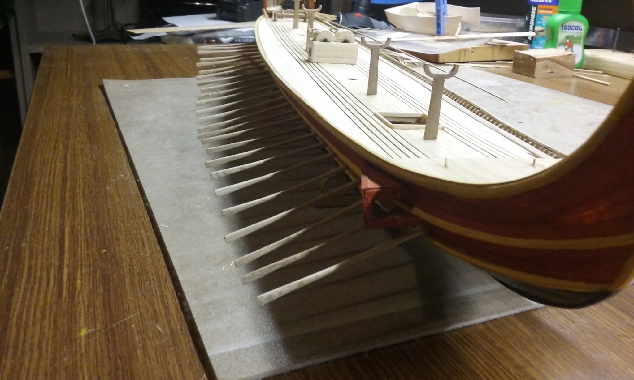
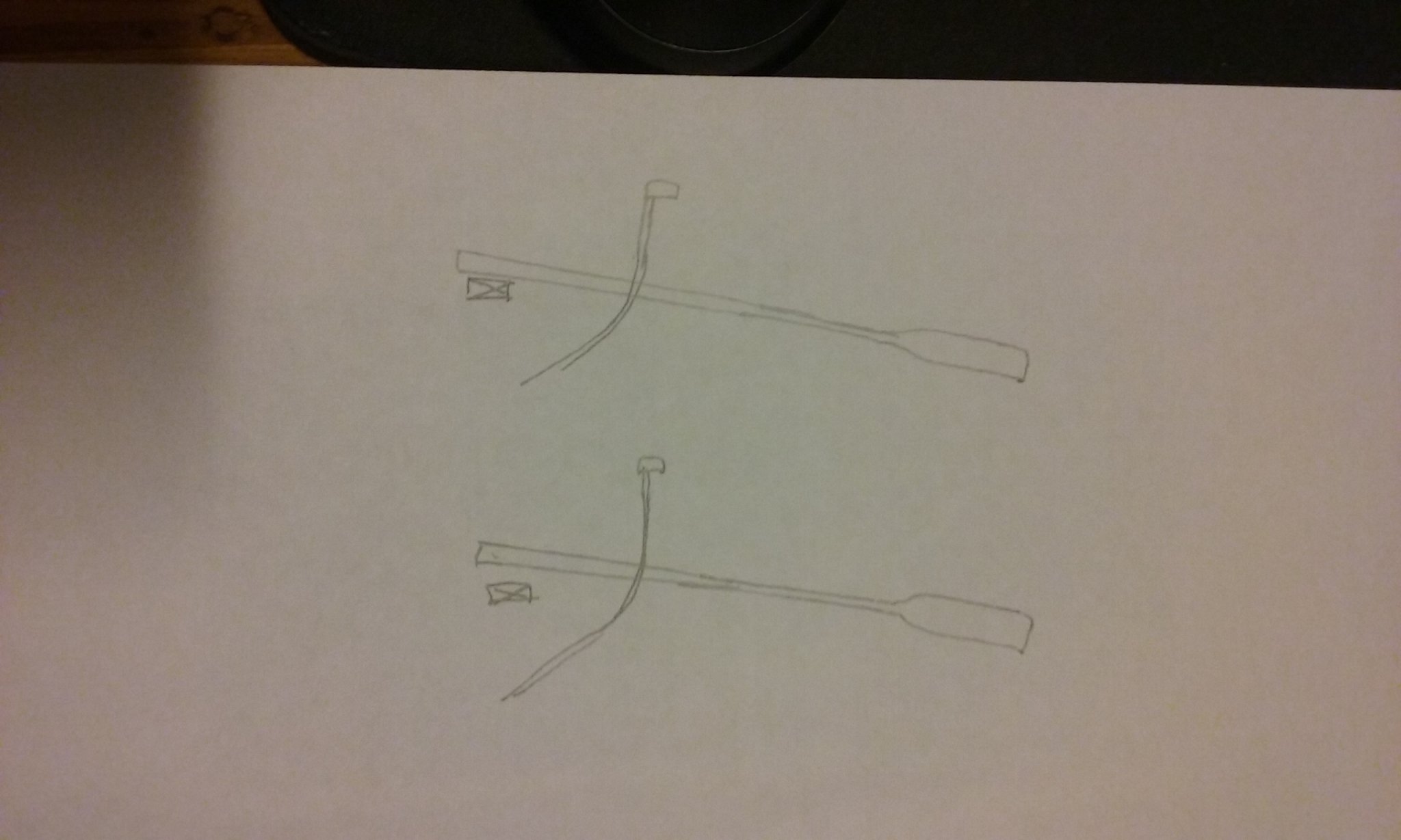
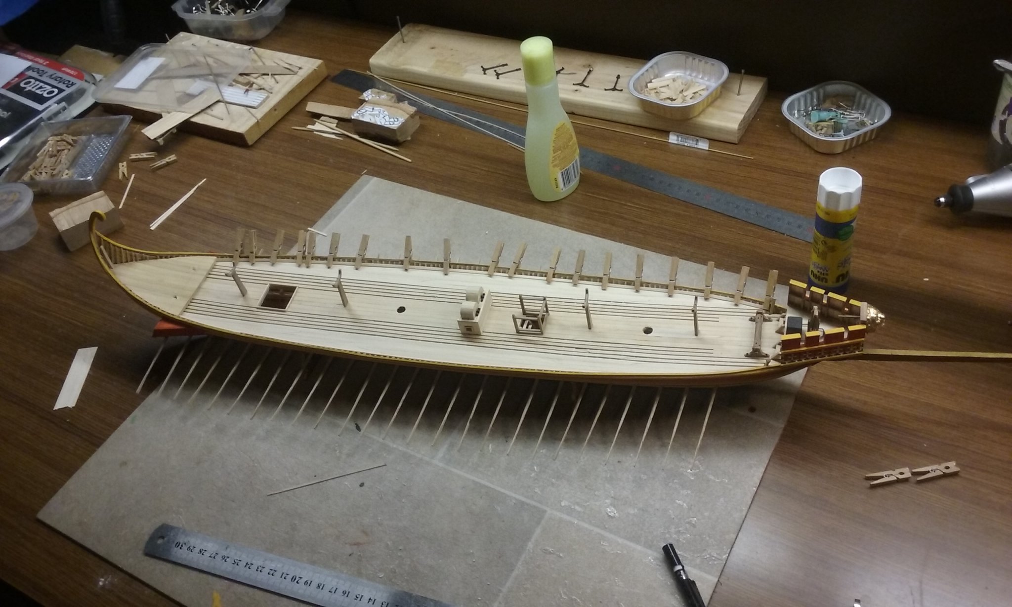
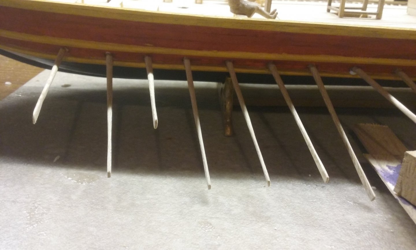
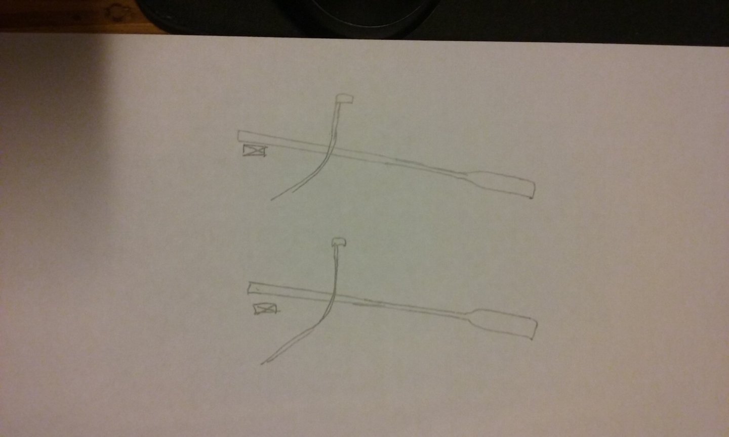
I glued all the oars into place. Looked good. A lovely line of oars, all at the same angle, with the blades all at the same height. I'd had a cunning plan, as seen in the top diagram below. Each oar was to be glued as it passed through the oarport and the inner end glued to a beam running the length of the ship, making it all very secure. But I'd made a mistake. I don't quite know how I came to do it. The first indication was when Pat (Banyan) asked me something on the lines of how I was going to make sure the oars were going to be kept in place when the ship was transported. I thought "no worries - I have already developed a cunning plan to deal with that". Unfortunately for reasons I don't recall (something to do with the angle of the bow-most oar) I only glued the oars at the oarport and not at the beam (as in the lower diagram), thinking "she'll be right" (Australian term for "I can't be fussed doing it properly - but what could possibly go wrong?"). Then AAARRRGGGHHH! The oars started to droop, and many of them were easy to push out of alignment. After considerable angst (in which I considered pulling off all the decking above the oars, replacing the oars and re-gluing the decking, which I'm sure would have turned it into a dog's breakfast) I decided the best thing to do was to pull each oar out of the hull and re-glue it to the inner beam the way I'd originally planned. Very labour intensive. Here it is with only a few oars re-done (note the base of a carved figure being used to push the oarblade up as far as it will go, to push the inner end down against the beam). I made sure that looking from directly above, the oars are all at the same horizontal angle (the one exception is an oar I haven't yet fixed). I've just finished doing them all, and for some reason despite the internal beam being nicely aligned, several of the oars are now a little too high or too low compared with the rest. Well, I've decided I just have to suck it up - the glue has set belowdecks and there's nothing I can do about it. And you do have to look pretty carefully to see it - as usual, the photos exaggerate the fault. And the alternative would have been much worse. Sigh. Steven


-
Ekis, I wasn't sure when the castle was due to be finished - I was quoting from memory. I agree - the castle itself is very modest- it doesn't even have a drawbridge - but it is nonetheless something that would have existed at the time - built by a minor lord on a limited budget. They also explain on the website what the revenues of a castle in such a place would have been and where they would have come from. My wife and I would dearly love to go to Guédelon some time in the future and work for a week or so as volunteer labourers (they actually let you do that!). Unfortunately it's almost impossible to get there unless you drive your own car (we've looked up the transport options) and we live in a country where cars drive on the left side of the road - not sure I'd be happy driving on the other side! Steven
-
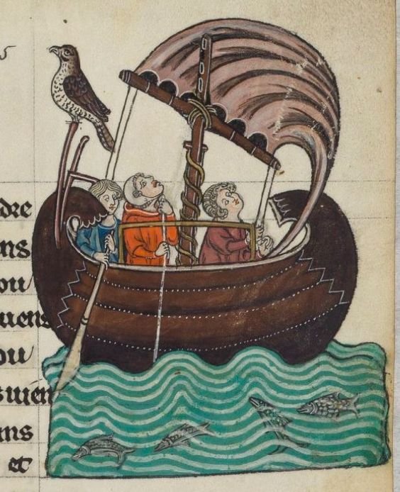
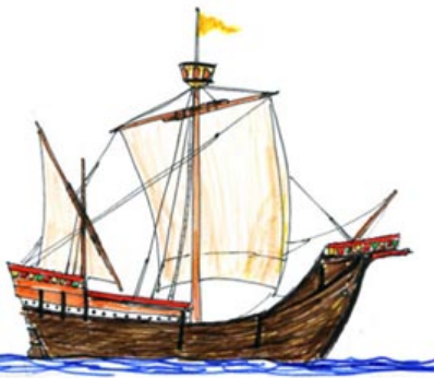
Beautiful work, Ekis. Judging by the architectural style, I'd place this in the Mediterranean region - southern France or Spain or perhaps Italy, and time-wise in the 14th century (mainly because of the form of the turrets and a few other military innovations that happened about then), though the church is Romanesque - presumably it was built centuries before and the fortifications either added later or updated as the centuries went past. If, later on you do build a little harbour, the ship(s) should also be from the 14th century. Though the picture below is from the 13th century a lot of smaller Mediterranean ships didn't change much over time, looking (allowing for artistic license) pretty much like this : By the way, for a bit of inspiration, have you seen the full size castle they're building at Guédelon using only mediaeval techniques at https://www.guedelon.fr/fr/. They've been building now for something like 20 years and don't expect to be finished for another decade or two. Steven
-
That's looking good, Peter. Nice and crisp. As I've already been in touch privately about your dad I won't add anything here, but our best wishes to you and Bernie. Steven
-
That's a very nice shape. Making good progress. Steven
-
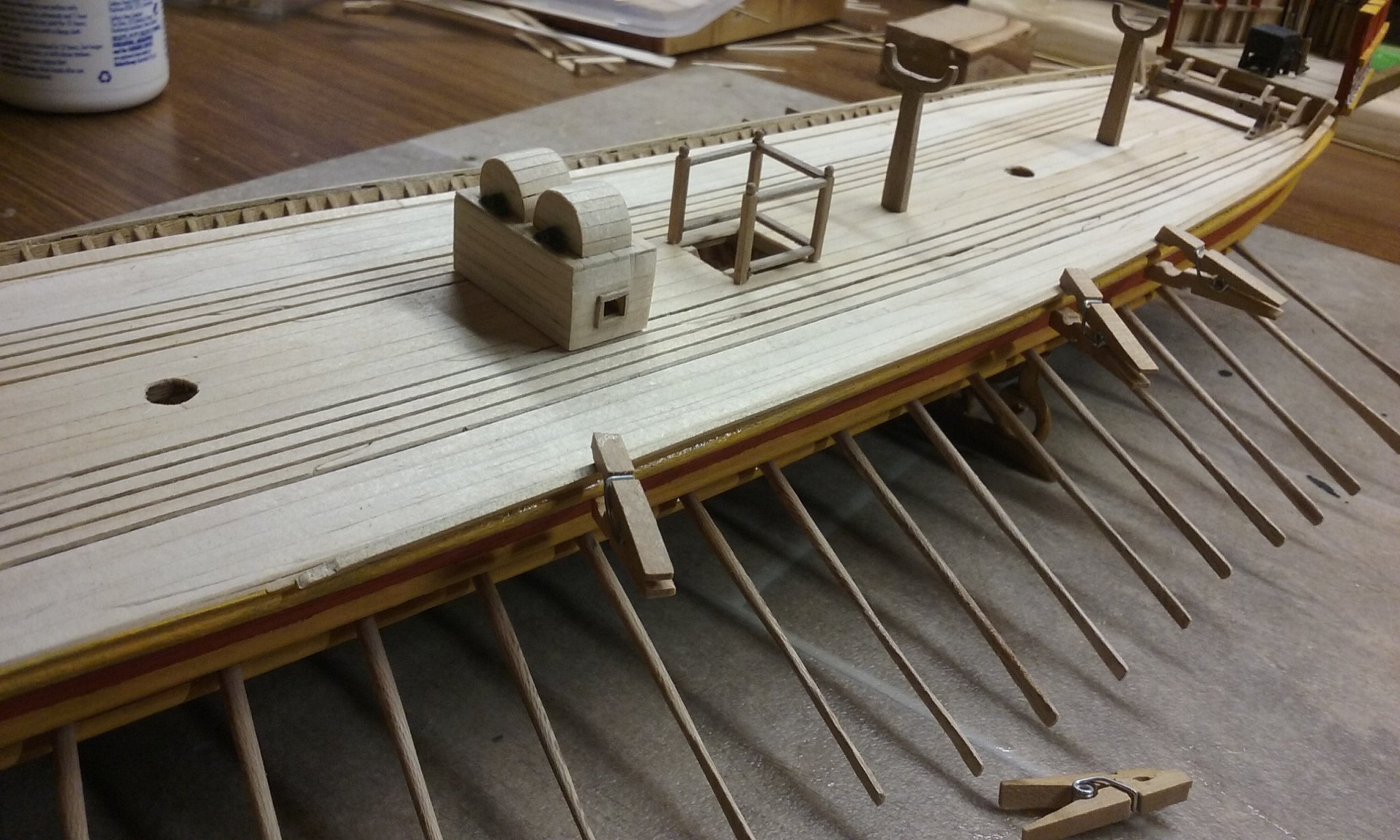
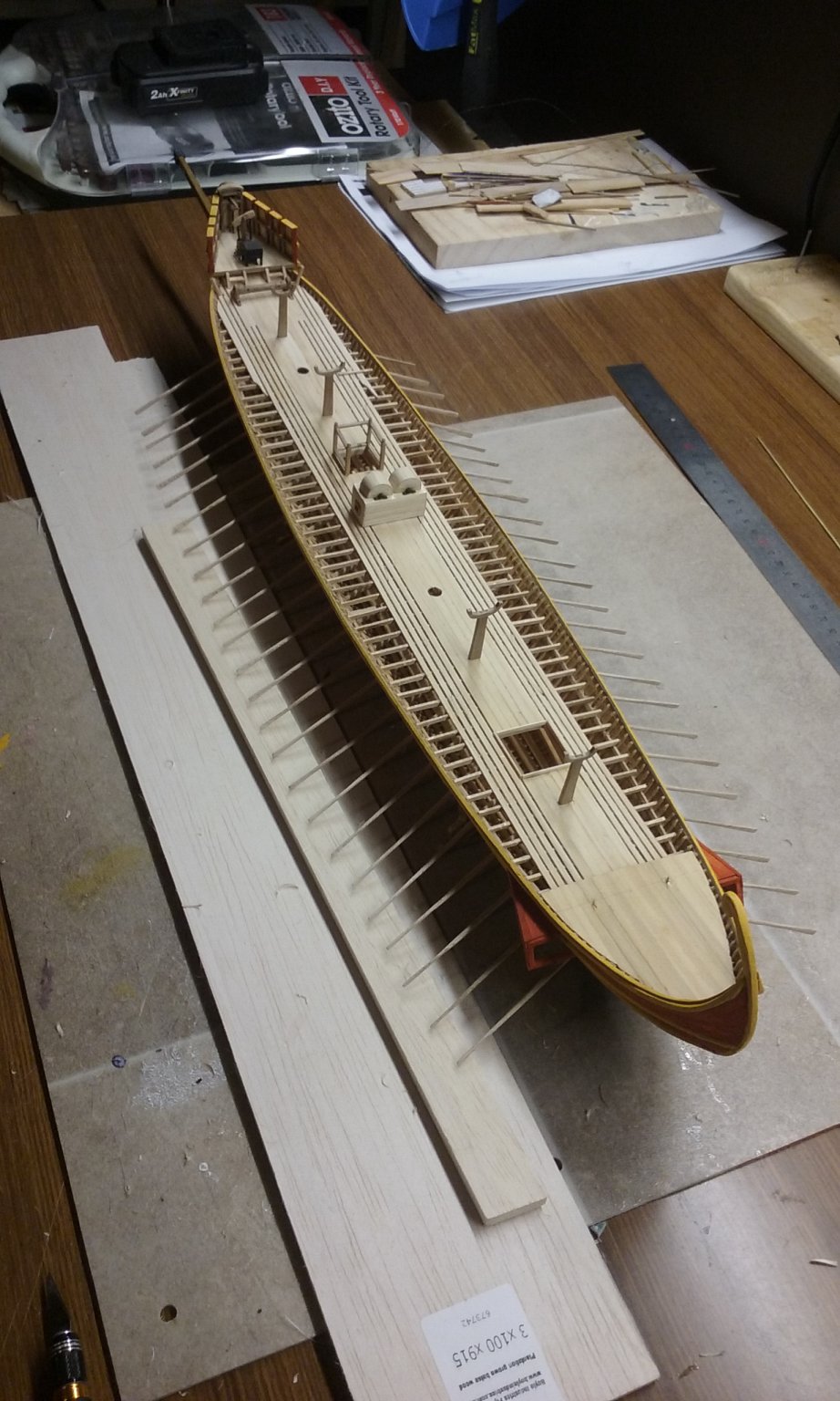
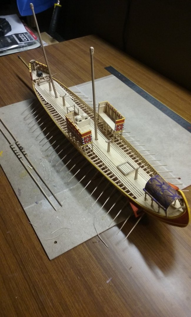
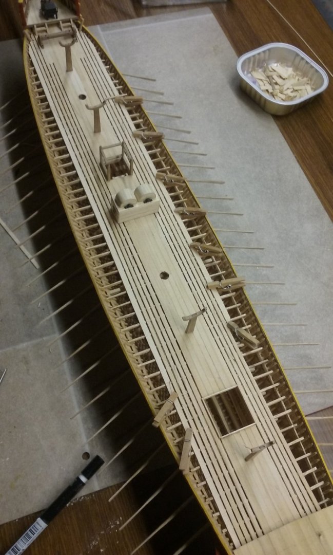
Thanks, GrandpaPhil. Pat, yes I'd thought of that and it is still a consideration, but it seems to me that if there was a heavy rain or big waves (though rough seas would be strenuously avoided as endangering a ship so inherently unseaworthy - lots of incidents of whole fleets of galleys being sunk by storms) the "gratings" in the centre (my solution to the lower oarsmen's need for lots of air if they were to function efficiently) could be covered with tarpaulins. As they tried to beach the ships every night if at all possible, to renew their water (oarsmen sweat a lot and need to drink a lot of water), they could pull out the bung and drain what water had accumulated in the hull. But they'd still want to avoid having to pump out more than absolutely necessary in between times, so they'd try to keep water from running down between the deck and the sides of the ship from the effects of spray. This is all highly theoretical of course, based purely on speculation on my part and I've no idea if that's what they really did. But till some archaeologist finds a dromon (maybe in the Black Sea?) who's to tell me I'm wrong? Anyhow, I've put in the waterways and they look pretty good. And now I've finally been able to start putting in the benches for the upper oarsmen. Steven


-
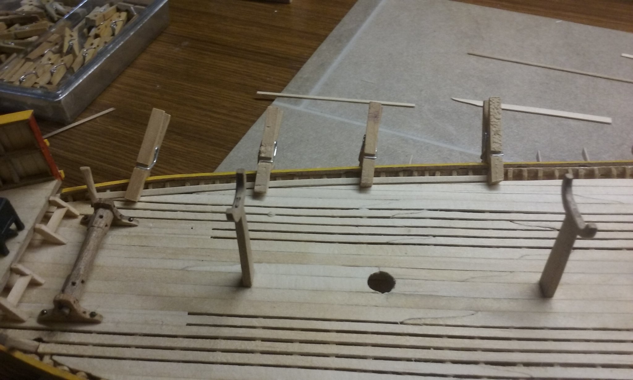
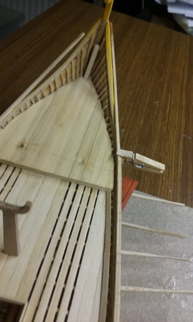
Thanks, Michael. Mark, I thought of doing that and it still might be what ends up happening. But that involves a lot of fiddly work (there's over 180 gaps to be filled). If instead I add inner planking, it would overlap the gunwale from underneath so I could extend the gunwale sideways (inwards) with another stringer which should (if I do it right) merge with the gunwale so they look like the same piece of wood. Here's hoping. Steven
-
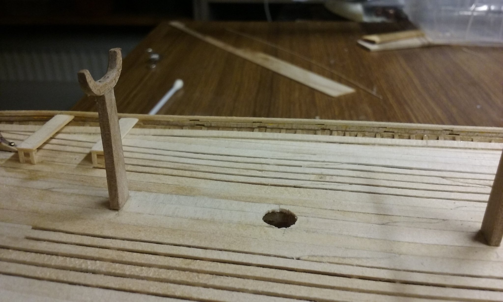
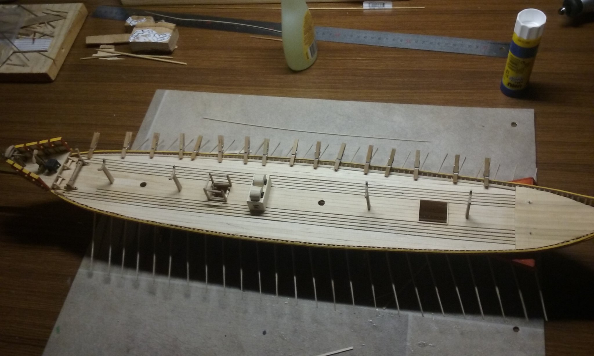
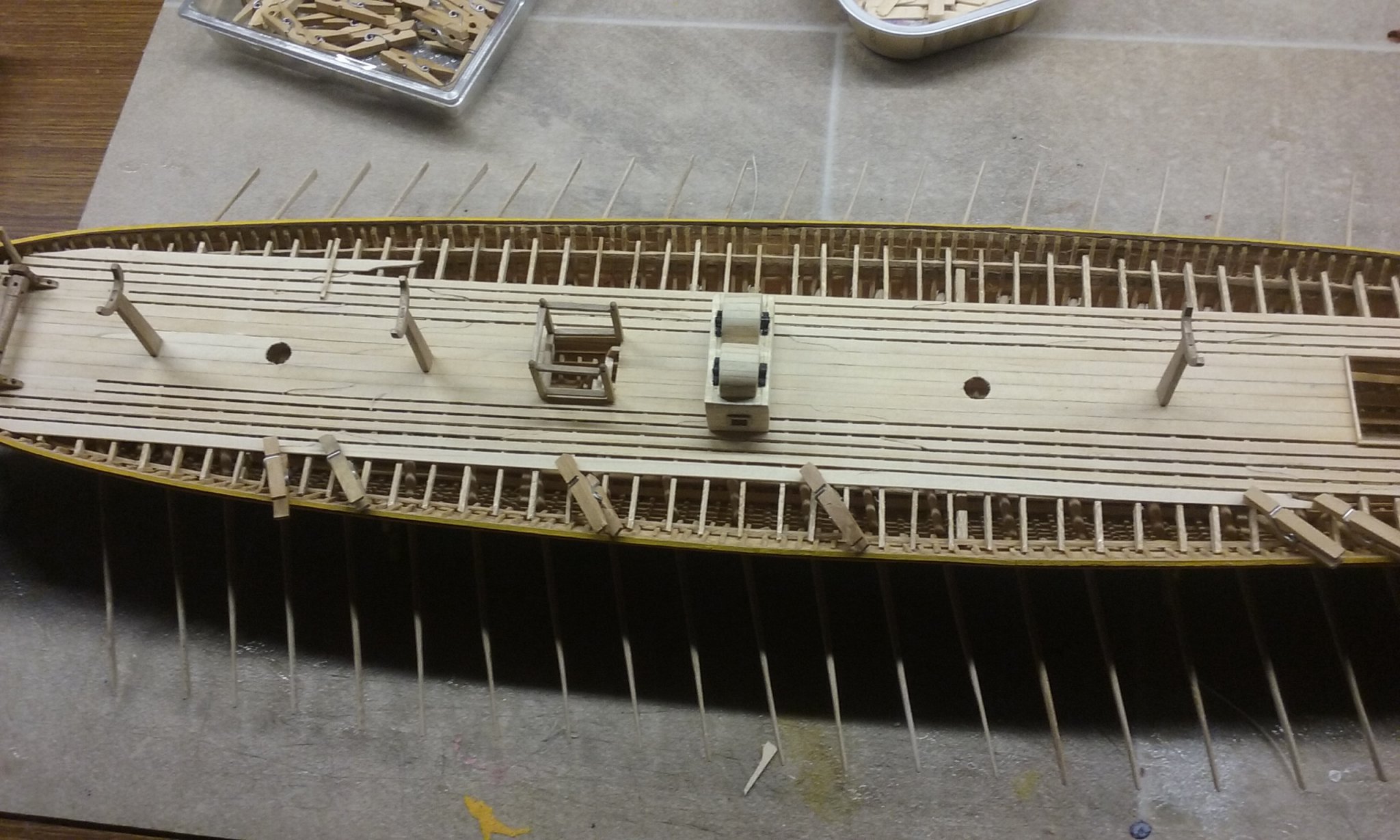
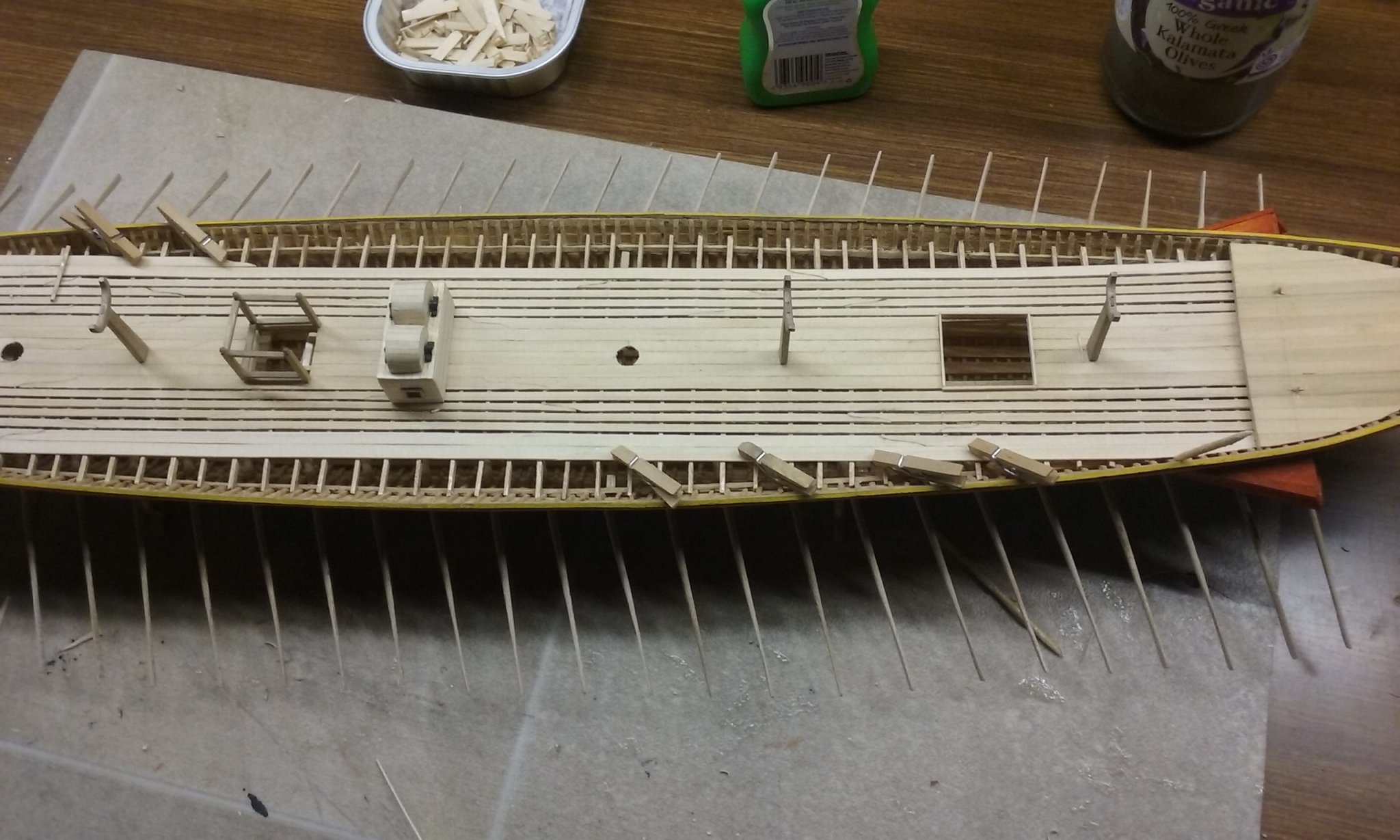
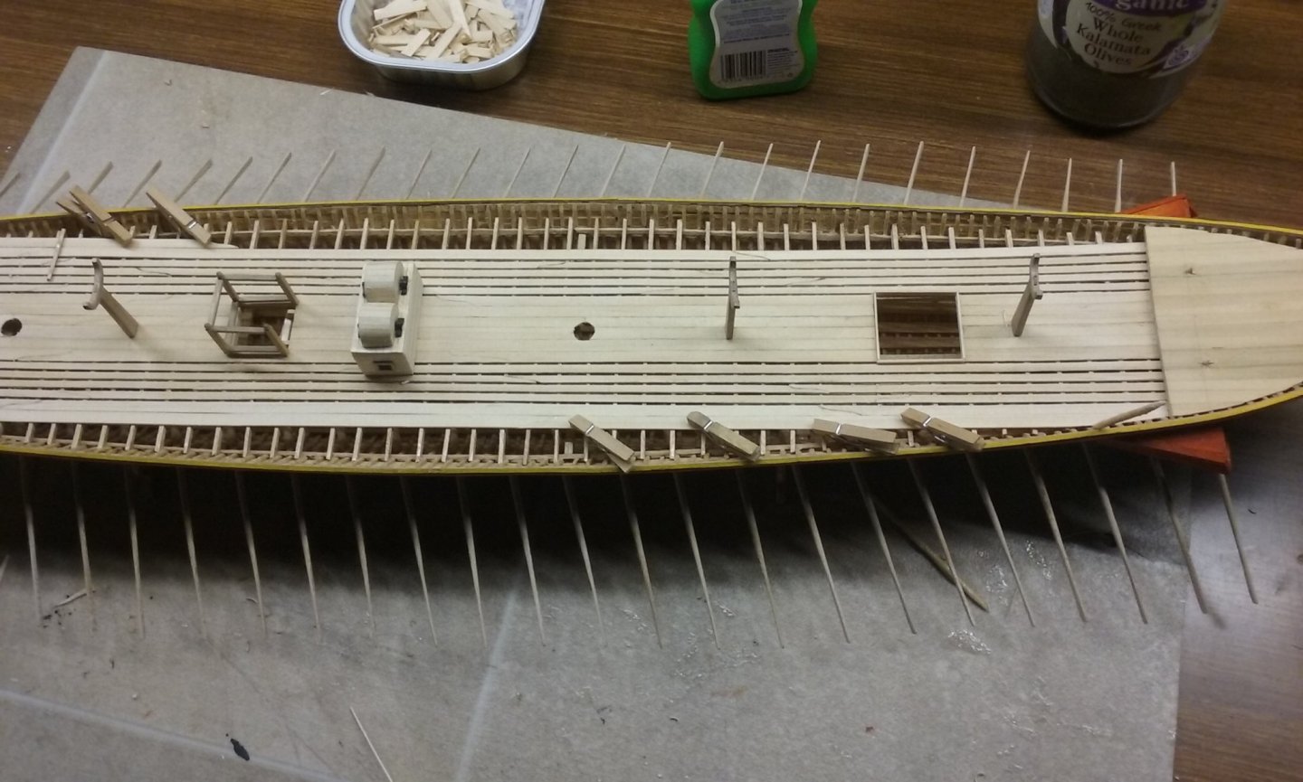
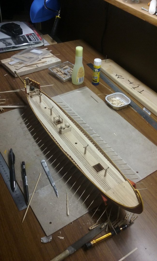
Thanks for all the comments and likes. Mark, thanks for your comment, but I am very aware this model isn't "museum quality". With an undetermined number of years of extra experience I might one day aspire to that kind of level - if I ever do - but it's certainly not now. Having glued in the lower bank of oars, I've now been free to complete the deck. Those little clothespegs are very useful, but of course towards the edges there's no longer any room for them, so I had to weigh the last few planks down with whatever came to hand. It seems to have worked. Now to sand down the deck to make all smooth. Then I have to face a problem I've been avoiding up till now. The original galley wrecks found at Yenikapi in Istanbul were single-banked and didn't have a deck. Accordingly they didn't have an inner planking - the inner sides of the frames were left open. There wasn't any need for an inner planking or a waterway to keep water from seeping down between the outer edge of the (non-existent) deck and belowdecks. Unfortunately this is not the case with the dromon, and I've been debating with myself whether to install inner planking at least above deck level, so there isn't a gap in the decking between the frames and the side of the ship. But if I do, the "wall" of the hull will be thicker than the gunwale is wide. So - do I add another stringer at the inner edge of the gunwale, so the planking doesn't overlap (or is that underlap) the gunwale? I think I have to. Decisions, decisions . . . Steven

-
Not at all, Safetman. In fact I agree with you that the forecastle on the Mary Rose was probably a hangover from the era of high forecastles designed as archery platforms, but among the last of them - soon to be superseded by the lower forecastles of the galleons which were already in use by the time she sank. And who knows? Perhaps they will find the remains of the forecastle after all. As I understand it, it's a matter more of finding the necessary funds to keep searching than anything else. I live in hope. By the way, given that nothing of the upper hull survives, the Time Team (or is Timewatch a separate programme?) statement of the Grace Dieu's forecastle height above waterline is probably based on a report of the time by the Florentine captain of galleys Luca di Masa degli Albizzi who I believe (if I could find my records) stated that her "prow rose more than 50 feet". Modern reconstructions that try to marry up this enormous forecastle with the length of the ship (admittedly 218 feet - about as long as the Victory!) end up looking quite bizarre and out of proportion: But as Albizzi also stated (if I recall correctly) the mast was 200 feet high, I do wonder how reliable his description is - did he take out a tape measure and check the dimensions? Or do "50 feet" and "200 feet" just mean "a helluva lot"? Steven
-
Not even a whipstaff - they don't seem to have come in until the 17th century. Which makes it a bit baffling - did they really just yell down to the helmsman which way to steer (because he couldn't see from where he was)? Chidokan, be a bit cautious with how far past the front of the carriage those "built-up" guns stick out - the watercolour from the 19th century recoveries shows the barrel only sticking out a short way - which is understandable - the barrel wouldn't have had all that much structural integrity and cantilevering it too far out without support would have imposed unnecessary forces on it. I envy you having your built-up barrels ready made; I had to make all mine by hand - not an easy job. It's a bit of a shame your pic of the fighting top didn't come out too well, but I found some good ones by doing a Google image search, which I hope are of use to you: Safetman, the Grace Dieu was from Henry V's time not Henry VI, launched in 1418, so over 100 years before the Mary Rose and the Henry Grace a Dieu (unfortunately the names are a bit confusing). However, your comments are still valid regarding the forecastle being a high platform for archers - that still hadn't changed by Henry VIII's time, though his two ships were probably among the last to be built that way, as firearms were in the process of making longbows obsolete. Steven

-
"I've had worse . . . "
-
Keep in mind also that the Mayflower wasn't a new ship in 1620 - the first mention of her is in 1609 - she was what the pilgrims could afford - the main (deck?) beam broke in a storm on the trip over and had to be supported by a "great scrue" - (several accounts interpret this as the screw of a printing press, while others claim it was a "jackscrew" intended for use in the construction of houses). Steven
-
Actually, the people he upset were the corrupt officials and landowners and members of the New South Wales Corps - the so-called Rum Corps, supposedly tasked with maintaining order in the penal colony but effectively gathering all power to themselves and their friends - "under the command of Major George Johnston, working closely with John Macarthur, deposed the Governor of New South Wales, William Bligh. Afterwards, the military ruled the colony, with the senior military officer stationed in Sydney acting as the lieutenant-governor of New South Wales until the arrival from Britain of Major-General Lachlan Macquarie as the new governor at the beginning of 1810." (https://en.wikipedia.org/wiki/Rum_Rebellion) The Rum corps and its ex-officers (such as Macarthur) had a very cushy position, having pretty much monopolised all the good land, kept the population in subjection, and bribery and corruption were rife. In the absence of a proper currency, rum (the production of which was under their control) was used as a medium of exchange. Bligh tried to stop the corruption but was was overthrown by a conspiracy of the Rum Corps. When Macquarie came out from England he brought in his own Scottish regiment, disbanded the Rum corps, introduced a silver currency taken from Spanish coinage (a disc was cut from the centre of each coin - the central disc being one value and the remainder, called a "holey dollar" was a different value. It was in his term of office that the colony really got properly established on a firm footing. Steven
-
Thanks everybody for the kind comments and the likes. Very much a learning experience, but I'm pretty happy with the way it's going. Steven
-
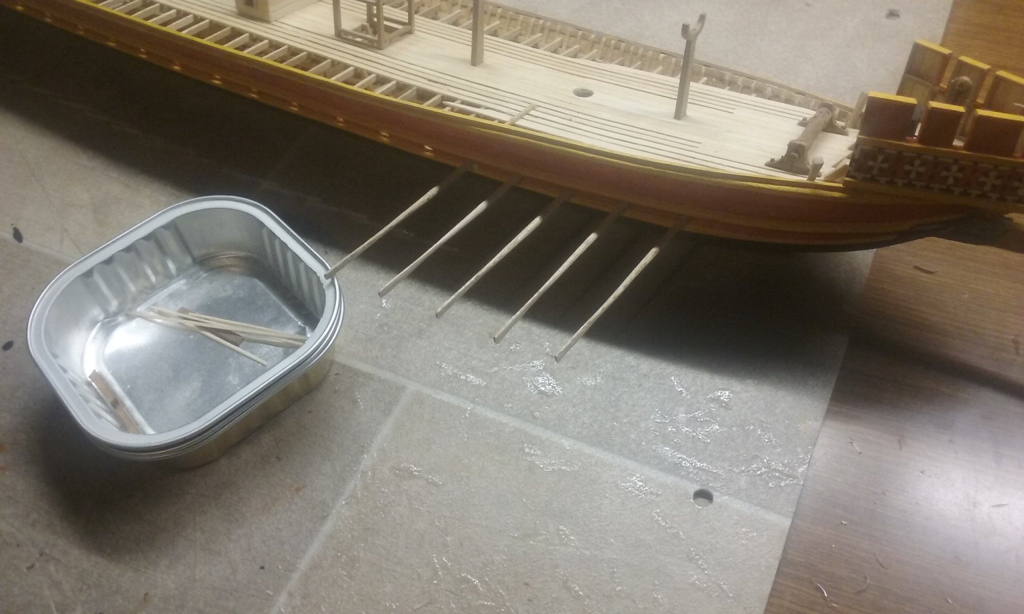
Been adding the lower bank of oars, one at a time - I had to wait till the glue dried on each before I moved onto the next, because a whole lot of oars with wet glue would be too hard to keep aligned without messing each other up. So here we go: To get all the oars at the same angle, I'd previously drawn parallel pencil lines on a long piece of wood below decks and aligned the oars to the lines. Note that the faithful cat-food container has again proved its worth: But I couldn't do it that way on the other side, so I came up with what turned out to be a better way. Steven