HOLIDAY DONATION DRIVE - SUPPORT MSW - DO YOUR PART TO KEEP THIS GREAT FORUM GOING! (89 donations so far out of 49,000 members - C'mon guys!)
×


Louie da fly
-
Posts
7,989 -
Joined
-
Last visited
Content Type
Profiles
Forums
Gallery
Events
Everything posted by Louie da fly
-
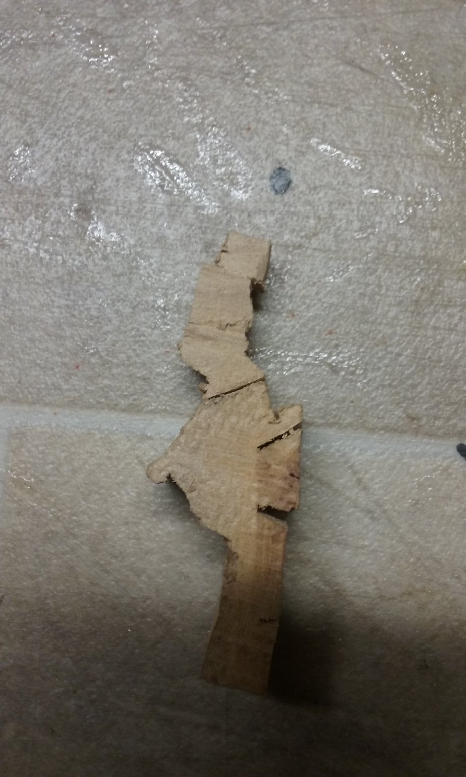
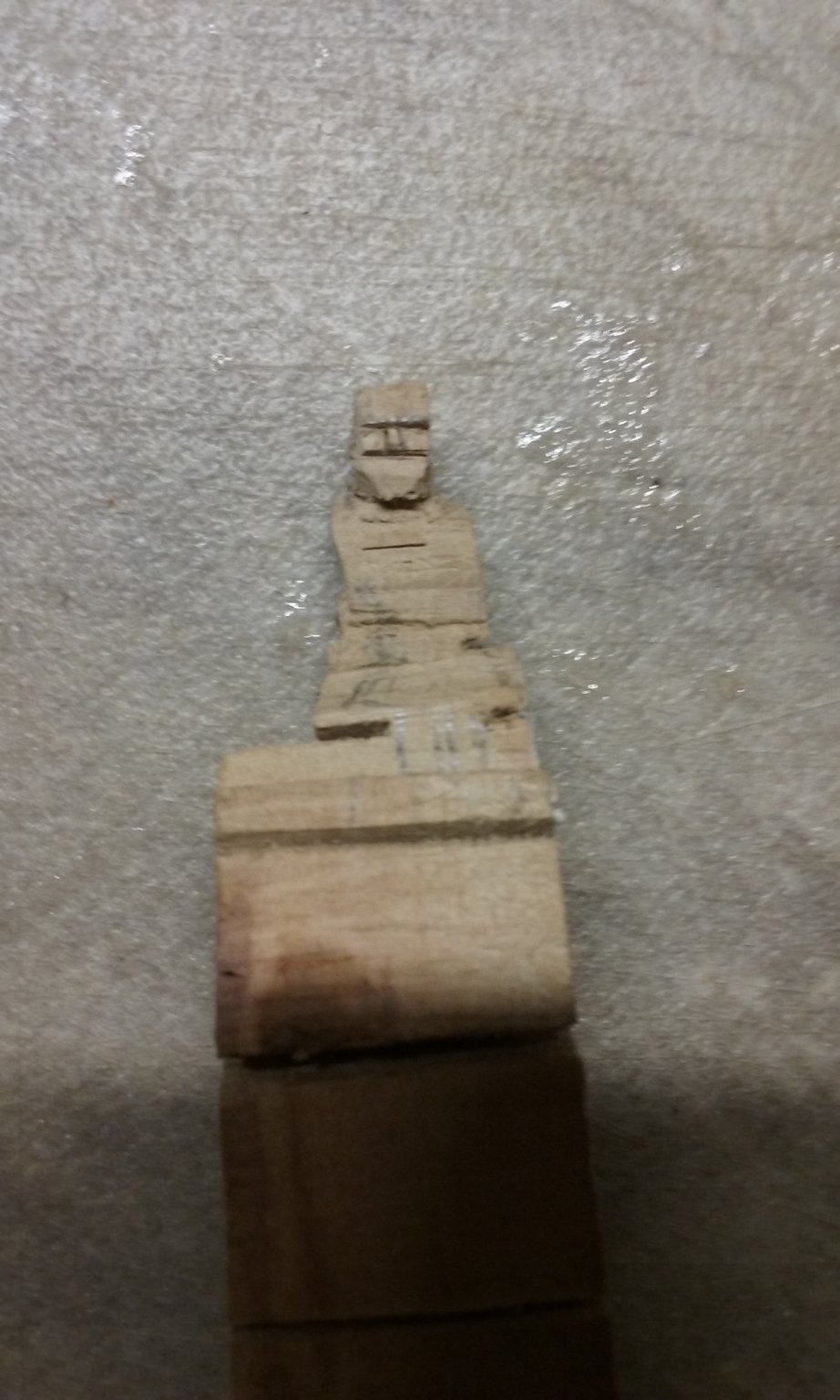
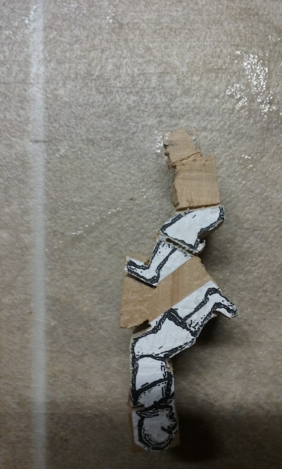
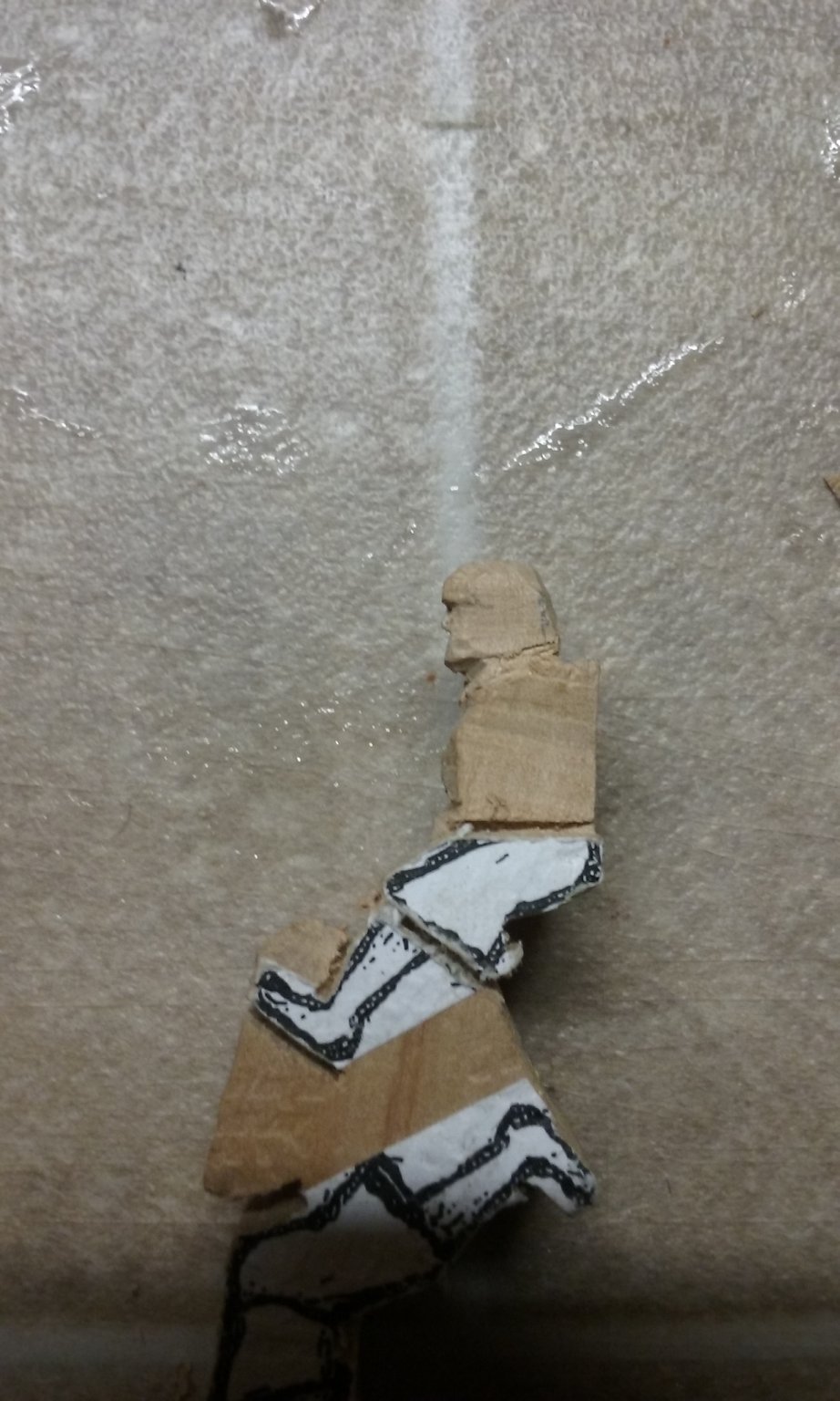
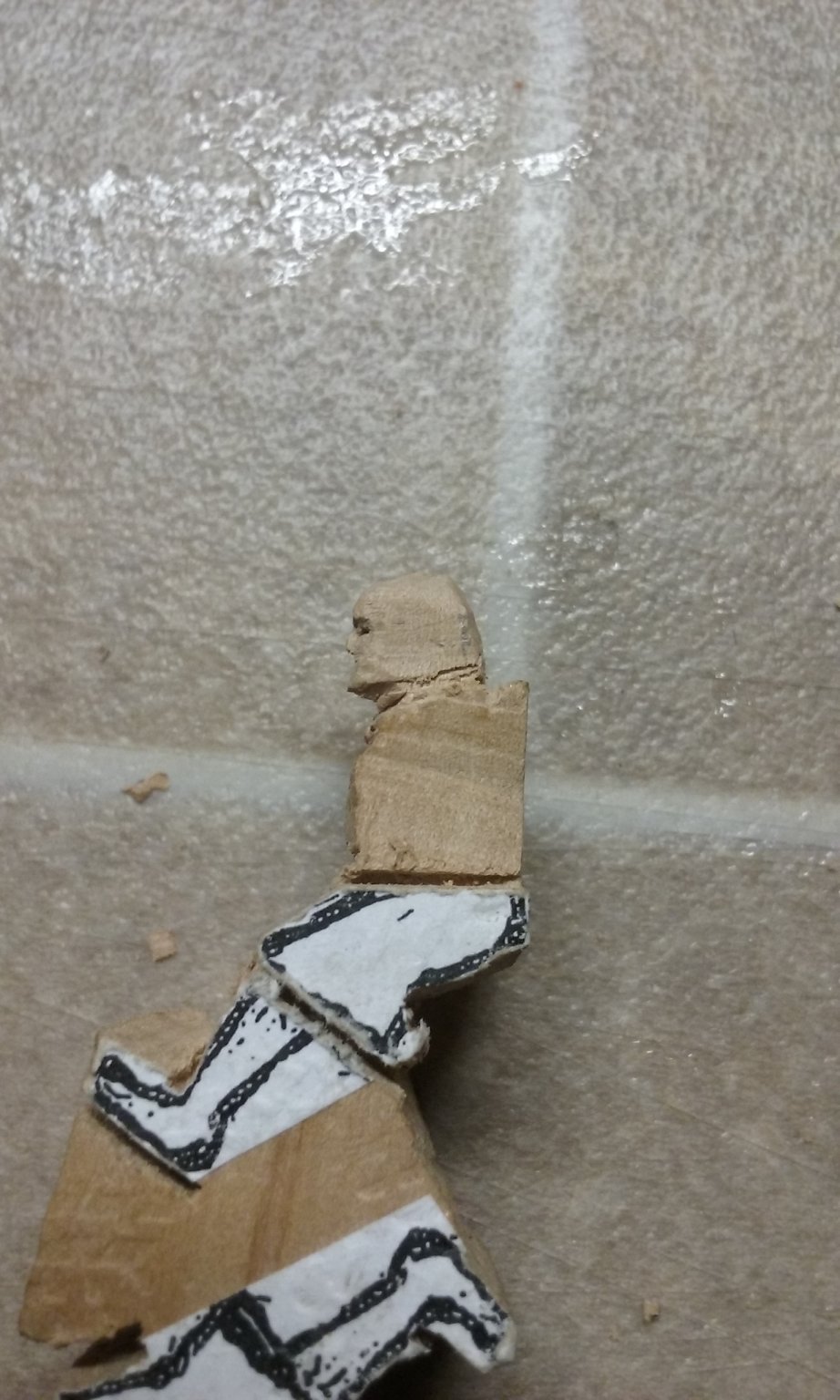
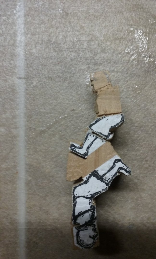
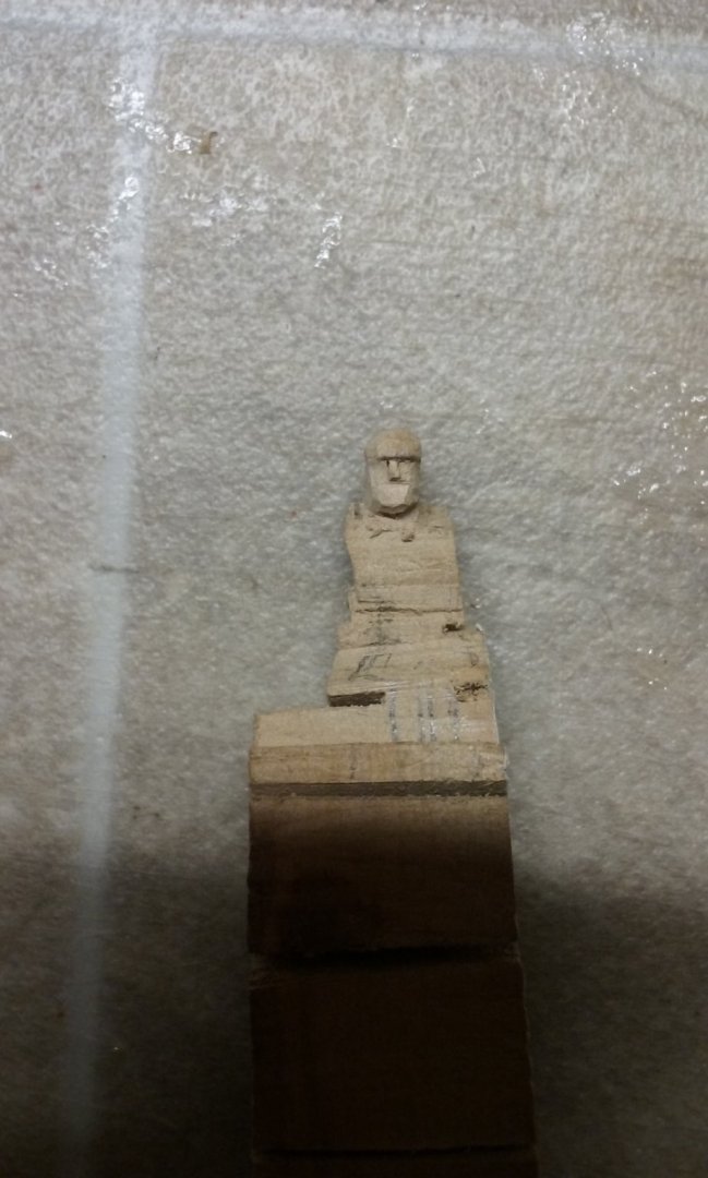
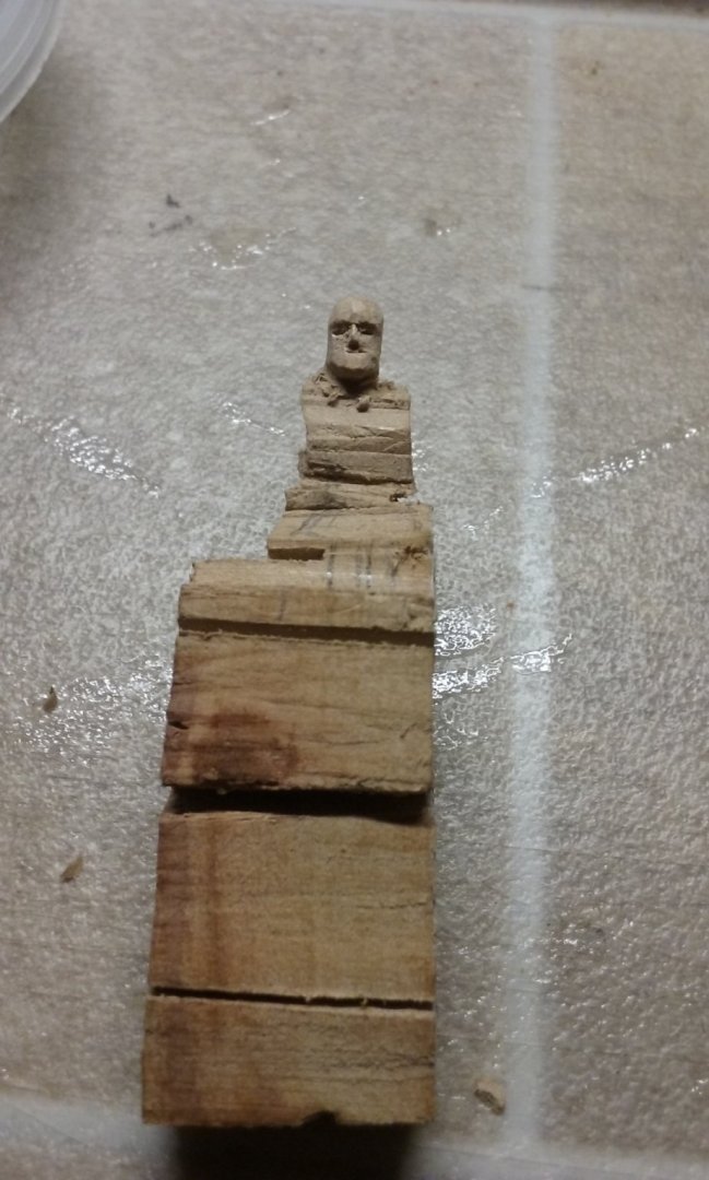
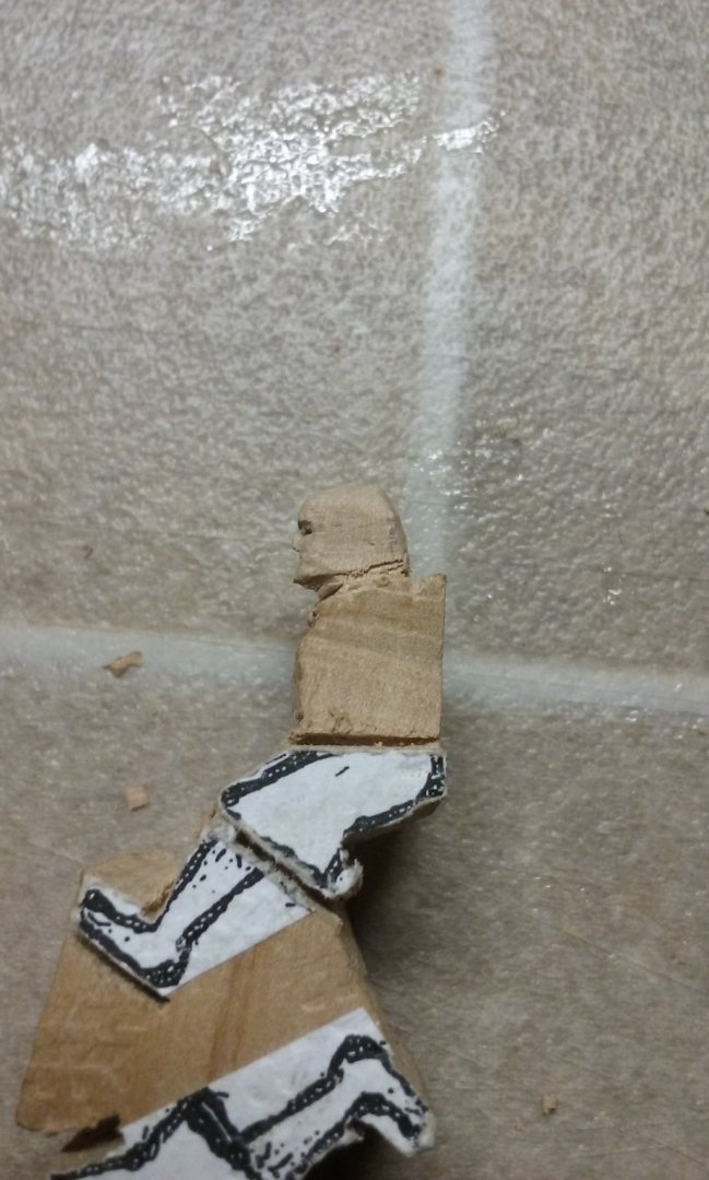
 I'm starting to work out the best way to make these oarsmen with least unnecessary actions - reducing the sawcuts to the absolute minimum needed, but even more to reduce the carving I need to do to a minimum. Here's the results of my first attempt. Having drawn a side view of the oarsman I made multiple photocopies and glued them to billets of pear wood, two to each piece, each with the head at the outside (top) edge - if I mess the head up, I might as well throw that figure away - it's impossible to fix it up - so I do that first. The reason for two to a piece is that it gives me a "handle" to hold while I work on the other figure. I found this out from grim experience. I sawed straight cuts approximating the outline of the side view. Then I turned the figure at right angles and marked the outline of the front/back view, and sawed straight cuts around that outline. Side: front: other side: Back: Next, carving the head with a No. 11 scalpel. Megatron: A bit of shaping: And yet more - perhaps a young Robert Redford? well, maybe not. I don't think Robert Redford has a nose quite like that: More later. But the system I've worked out seems to work pretty well with a good balance between sawcuts and carving. Steven


-
Thanks very much for the offer, Pat. I'd dearly love to take advantage of it, but we've decided to limit our travel and contacts to the absolute minimum for the time being - at least until the situation is clearer. We've even cancelled (or at least postponed) the grandkid's 3rd birthday party. So until further notice I'm restricted to using a coping saw to cut the figures out. What with that and the work still to be done in the garden (we're going to put in a concrete path with decorative stone inserts) I won't have a chance to get bored. Steven
-
Hi Borden and welcome to MSW. From your introduction it seems you've already decided on a model to make. Do you have any type of ship or time period you're particularly interested in? There's lots of choice available, from steel battleships to ships of the line to rowing boats. All good fun, all interesting. Sometimes too much choice available - like a kid in a candy shop. Don't forget to begin a build log when you get started - you'll get lots of encouragement and helpful tips from fellow members. And have a look at other people's build logs. Often problems that you encounter in your build have already been solved in someone else's log. Anyhow, welcome again. I look forward to seeing your progress. Steven
-
Thanks for all the likes, everyone. Pat, after a fair bit of trial and error, once I'd figured out how to do a mass-production run it turned out to be pretty easy and fast. The main problem was drilling accurately enough. And then I had to go through and widen each hole with a dressmaking pin - I don't have any drill bits between 1mm (much too big) and 0.38mm (somewhat too small). Making the crew, on the other hand - that's going to take quite awhile. A lot of woodcarving ahead, I'm afraid. Still, if I pace myself (and let's face it, I won't be leaving the house much from now on) I should be able to make steady progress. One thing I need to do is work out a way to reduce wasted effort in shaping the figures - sawing each figure roughly from a block of wood and then carving off large bits that are just in the way - so I can get down to the serious stuff of making the figure itself. I'm sure I'll be able to work something out to make the process more efficient in terms to labour and time. Steven
-
Dammit! I've always loved pre-dreadnoughts and this one is a beauty. Almost makes me want to go over to the Dark Side - but the bar is far too high for a duffer like me. I think I'll just have to stick to wood and early ships (plenty of choice there to keep me busy for a lifetime!) Steven
-
HMCSS Victoria 1855 by BANYAN - 1:72
Louie da fly replied to BANYAN's topic in - Build logs for subjects built 1851 - 1900
Lovely work, Pat. I'm very hamfisted with soldering. Your work leaves me awestruck. Steven- 1,013 replies
-
- 5
-

-
- gun dispatch vessel
- victoria
- (and 2 more)
-
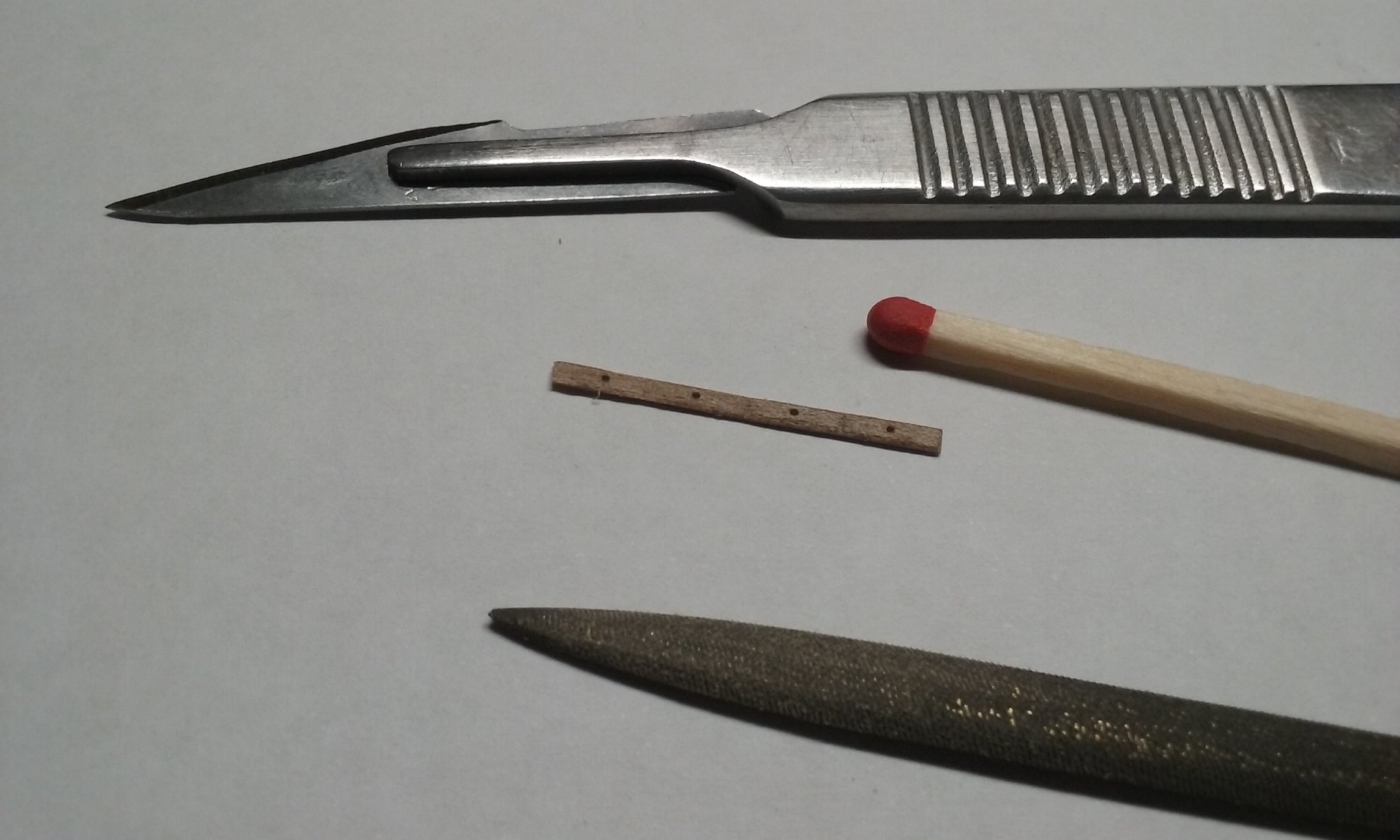
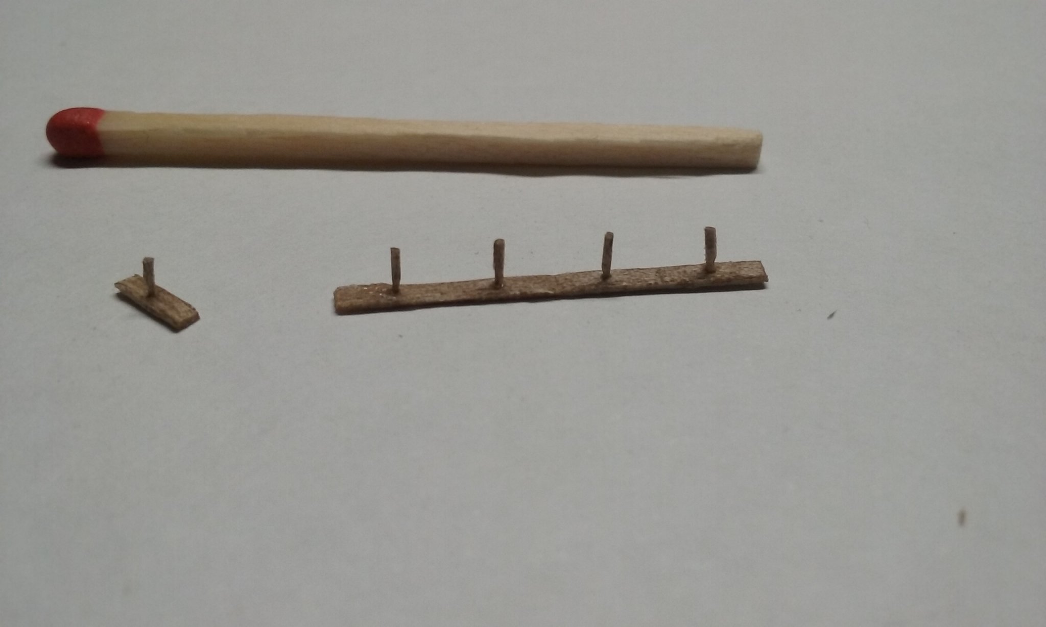
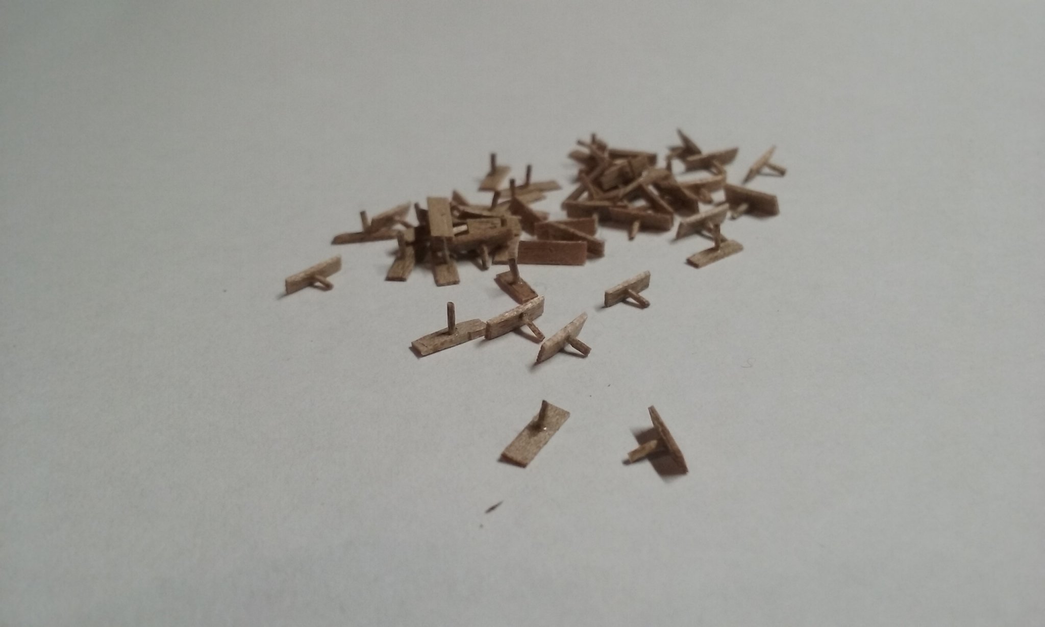
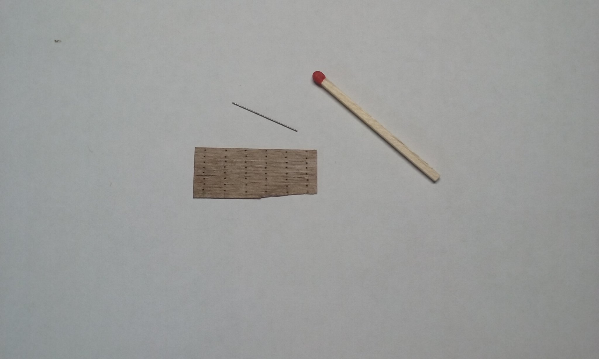
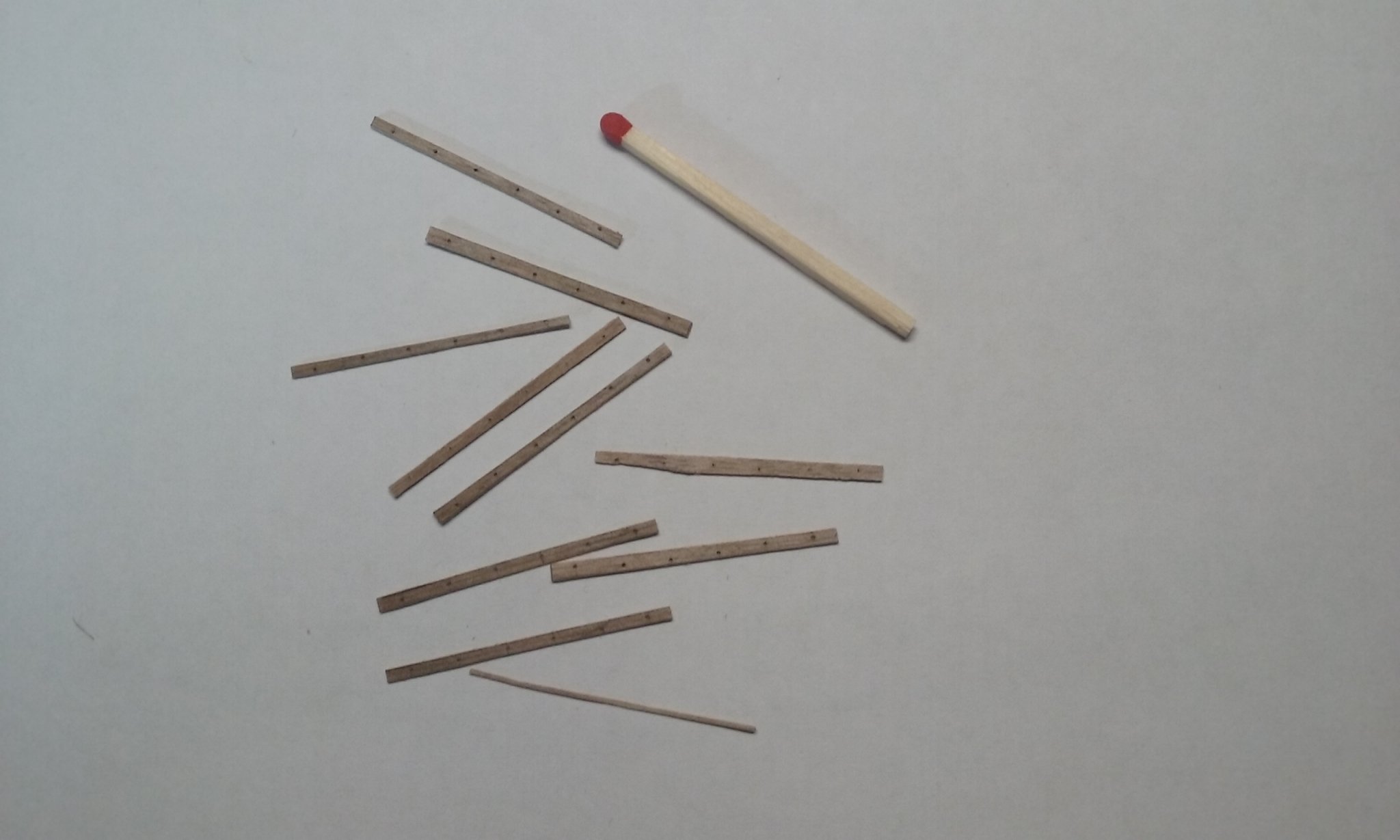
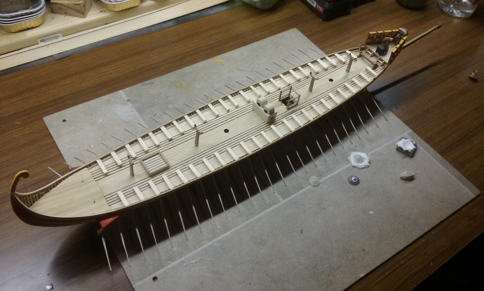
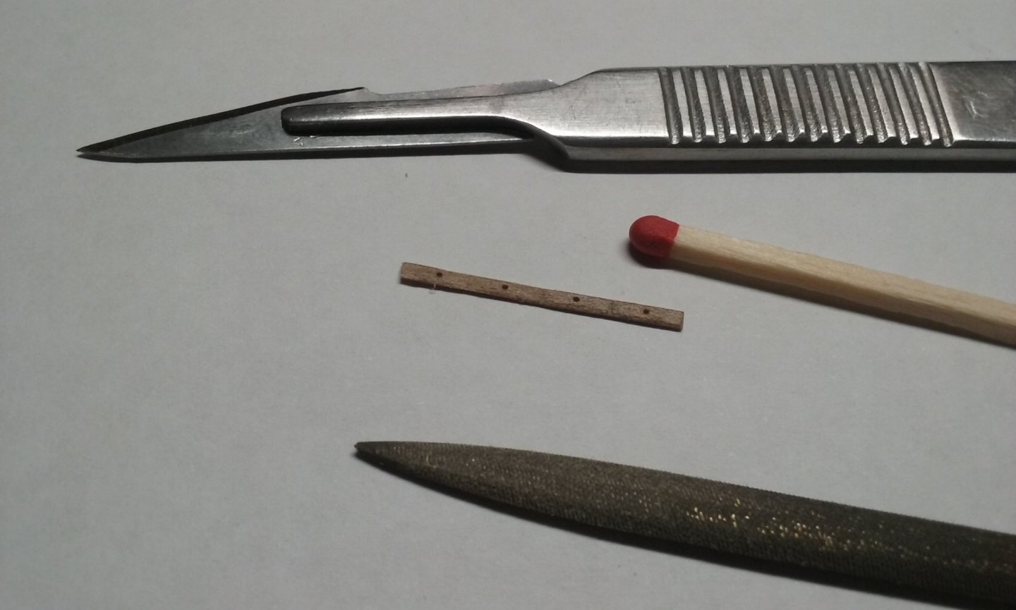
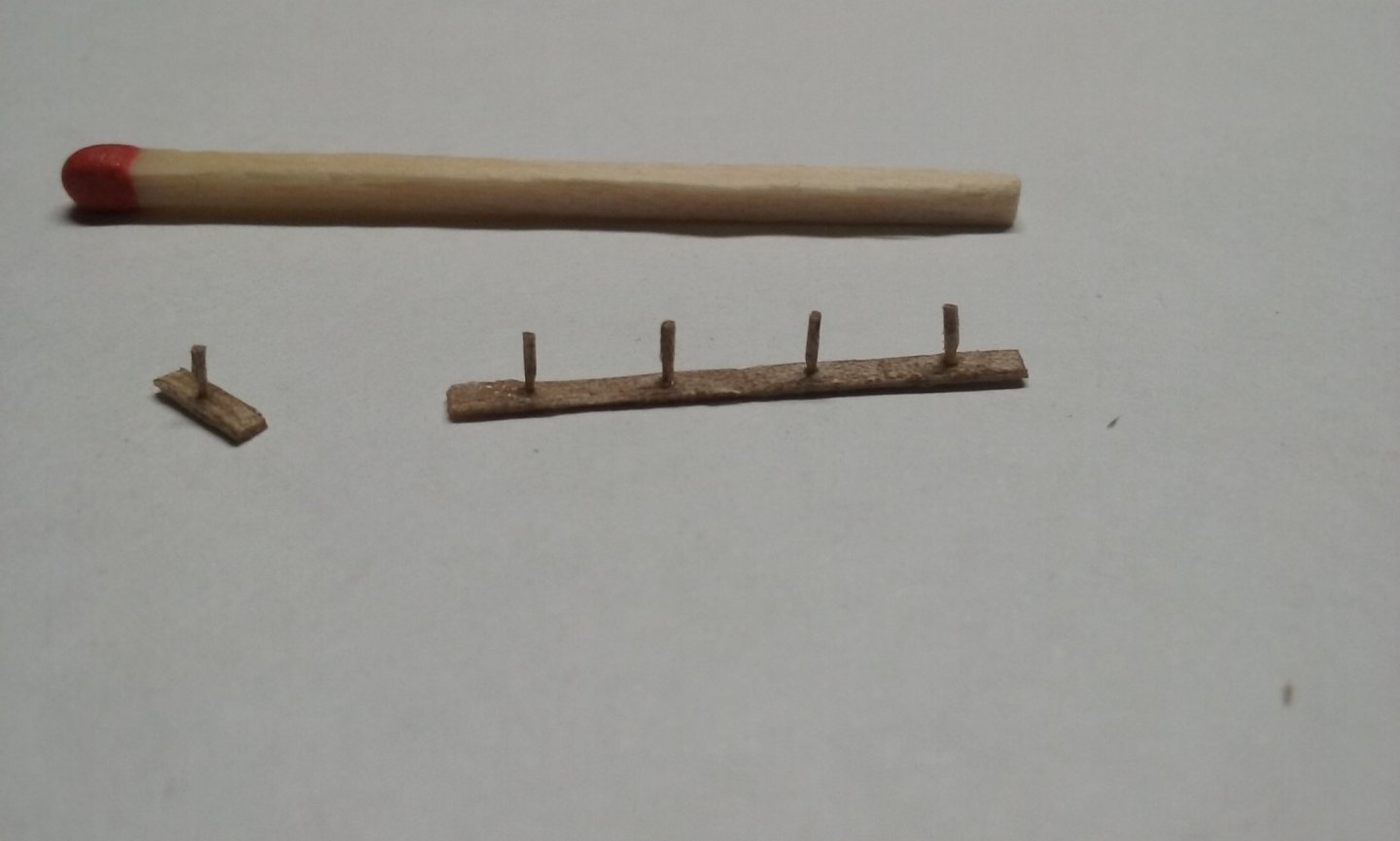
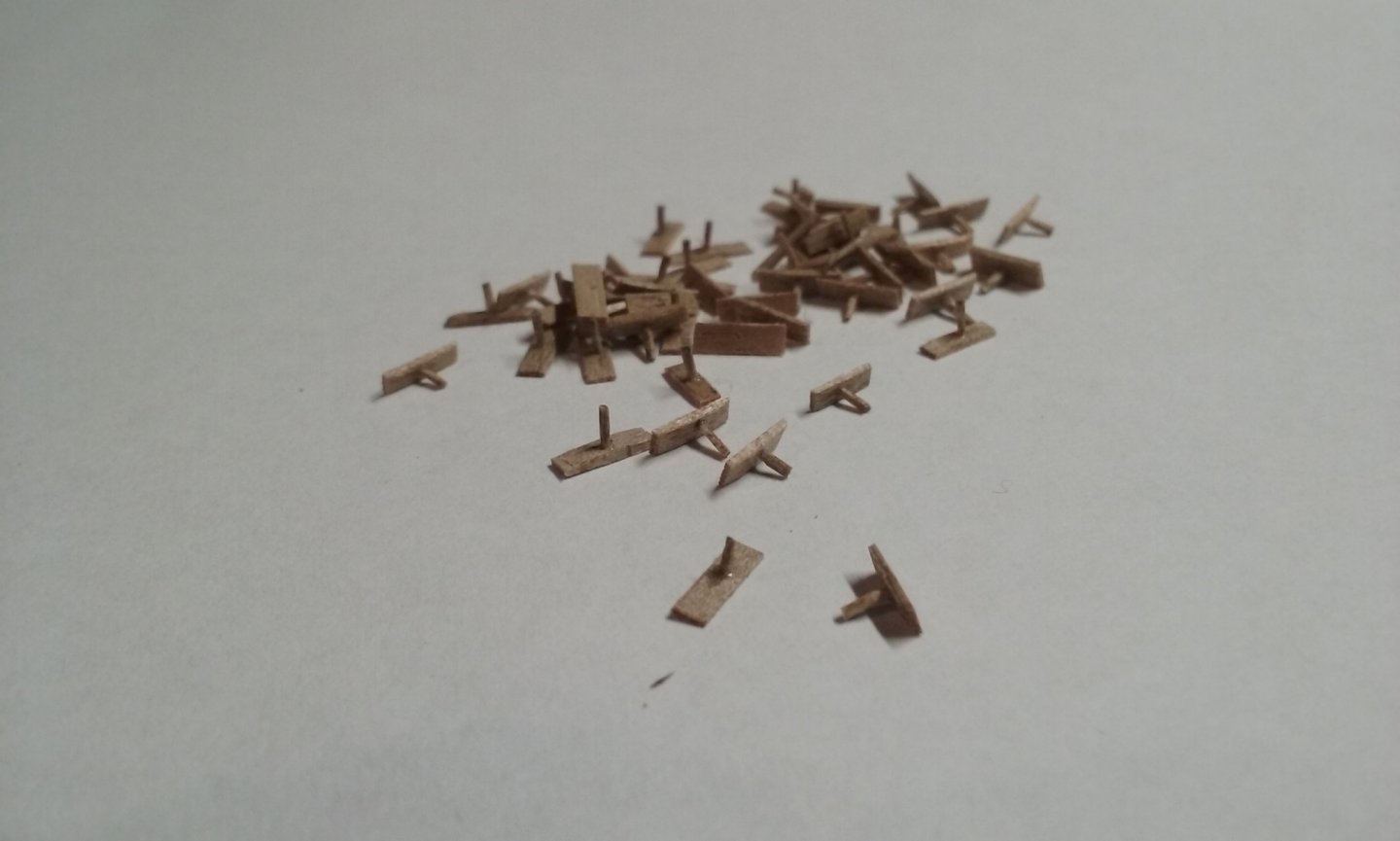
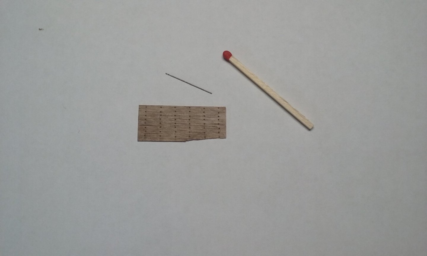
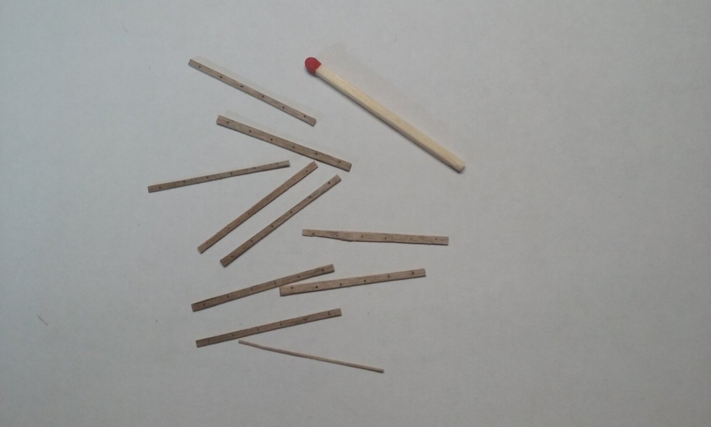
I've now made the tholes and their sockets for the upper bank of oars. I worked out a way to mass produce them, which seems to have worked nicely. A sheet of wood 0.5mm thick (25mm=1 inch at 1:50 scale) marked into strips, each of several sockets, with 0.38mm holes drilled for tholes. As it turned out there was a fair bit of wastage (ever tried to drill a 0.38mm hole in the exact middle of a strip of wood about 2mm wide with a hand-held electric drill?), so I had to make more strips later. And cut into strips. Ends tapered in the vertical dimension to make the sockets "hump-back" shaped, and edges smoothed off. Tholes with a tenon at one end, cut to length and glued into the holes. Later I found it was better to cut the socket pieces apart before inserting the tholes. So now I have 54 tholes and sockets, allowing a few spare in case of stuff-ups. Next thing is to mark the thole positions on the gunwale to help determine where the uprights have to go for the pavesades (the railings that support the shields) so they don't foul the oars, and the same for the posts supporting the xylokastra (defensive wooden castles). Steven
-
Beautiful work, Ekis. Very convincing - it really gives you the "feel" of the time and place. Steven
-
Horses for courses, mate. The detail on your Victoria leaves me amazed. Granted that hand-painting is a different set of skills from making tiny bits of equipment - I have great trouble achieving the level of precision others are capable of in making tiddly little bits. I hope to improve, but I have to balance making tiddly bits to the level of precision I'd like to aspire to, with wanting to eventually actually finish the ship in my own lifetime! Steven
-
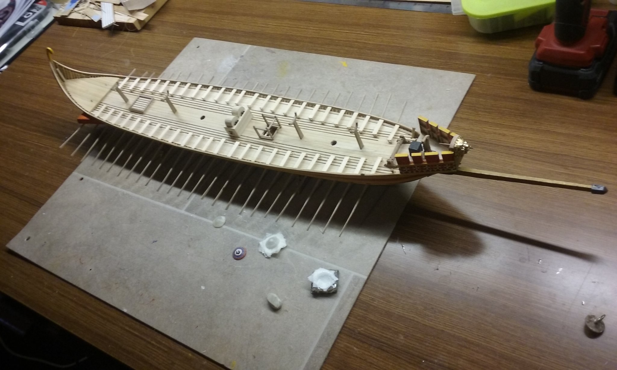
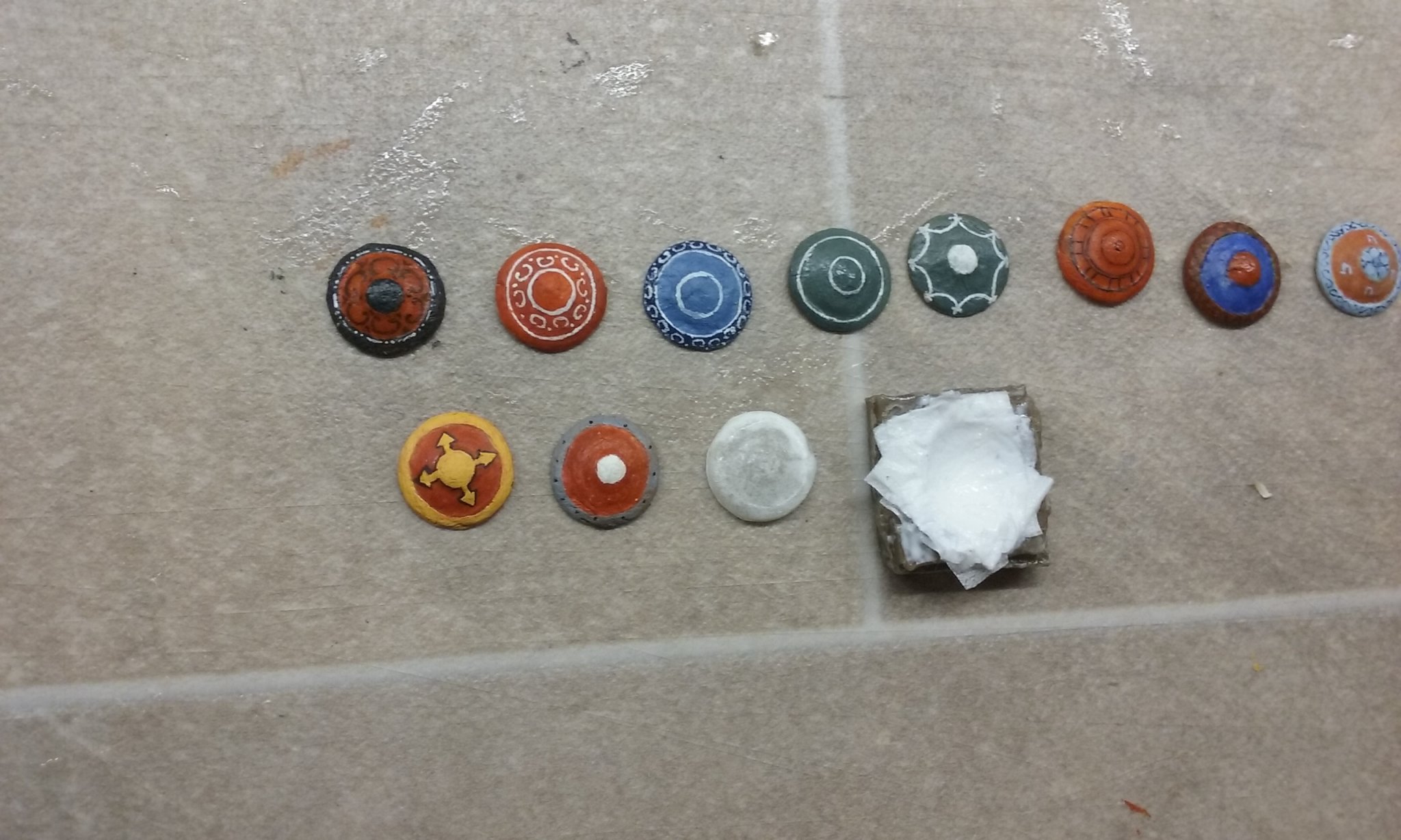
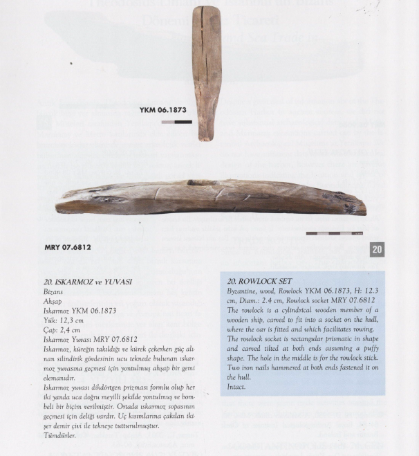
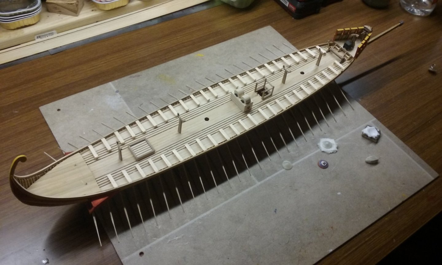
I've finished putting the oarbenches in place. My next job is to make 50 tholes and their bases, as found in a Byzantine shipwreck in Istanbul. And I've made and painted another six new shields (the ones in the bottom row - again, taken from original Byzantine illustrations), with two more ready for painting and another one under way, a total of 19 so far - another 31 to go. They each take about a day to make. Steven

-
Nice solution to the problem, Patrick. And to your usual high standard of research and workmanship. Steven
- 756 replies
-
- 2
-
-
- galleon
- golden hind
- (and 2 more)
-
As I mentioned above, it depends what you want to use it for. That's still quite a large amount of money, even if it's exactly what you want. As I know nothing about the circumstances, I'm not in a position to advise whether or not to get the printer - that's a decision you'll have to make for yourself. In certain uses it'd be very worthwhile, but you know best what you want and whether you'd get enough use out of it to make the purchase worthwhile. For example, if you had an A0 AutoCad drawing and wanted to print it off, it might be much cheaper and more economical to just take it down to a printing works and pay them to make one or more copies at A0. A few bucks instead of $922. Steven
-
I'm not familiar with the model, but if you want to draw plans for your own vessel on AutoCad or a similar drawing software, a good printer would be indispensable. Having checked the specs, this printer prints on either 24 inch (610mm) or 36 inch (914mm) paper paper, which is pretty big. The 24 inch will take A1 paper, and I suppose the 36 inch must take A0. What size is the one you're looking at? It should be suitable for full-size plans for anything up to a pretty large-scale model. Using AutoCad (that's the one I'm familiar with, but I'm sure others would work as well or even better) you could, for example, generate your own plans, side-views, and even your own cross-sections to paste onto wood to make your frames. It all depends on what you want to do with it, but I'd be very happy to have one myself - my printer only prints up to A3 paper (11.7x16.5 inches or 297x420mm) and, for example my 30-odd metre (90 foot) dromon at 1:50 is too big for it to print a side or top view at full size. If you want to make anything 1:50 scale or bigger the T520 sounds good. As I said, not familiar with the model, but HP have a pretty good reputation. Steven
-
Not yet. I'm now going to have to look at my options, and maybe silkspan will be one of them. I haven't used it before but I've read a lot about it on this forum. If I got enough of it for a flag or two I might as well get enough for sails as well. But what I'd particularly liked about the foil was that it was fine enough to make really narrow tails for the flag, but stiff enough for even the tails to be pretty much self-supporting. It's annoying to have to re-think it after I thought I had it sorted. Steven
-
A very nice restoration of a model which I'm sure has - and can now continue to have for a long time - a lot of sentimental value to you. It's certainly a very dramatic and impressive transformation from the original condition to the finished product. Steven
- 4 replies
-
- 2
-
-
- santa maria
- carrack
- (and 2 more)
-
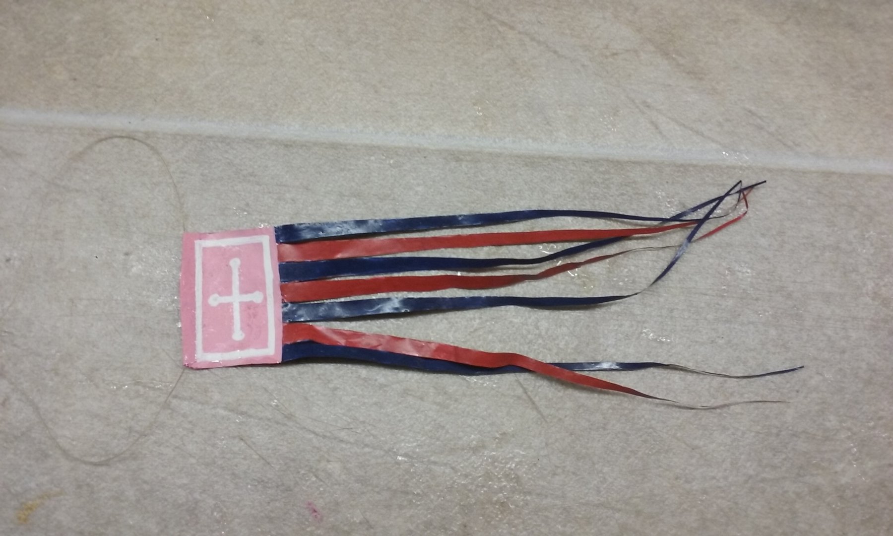
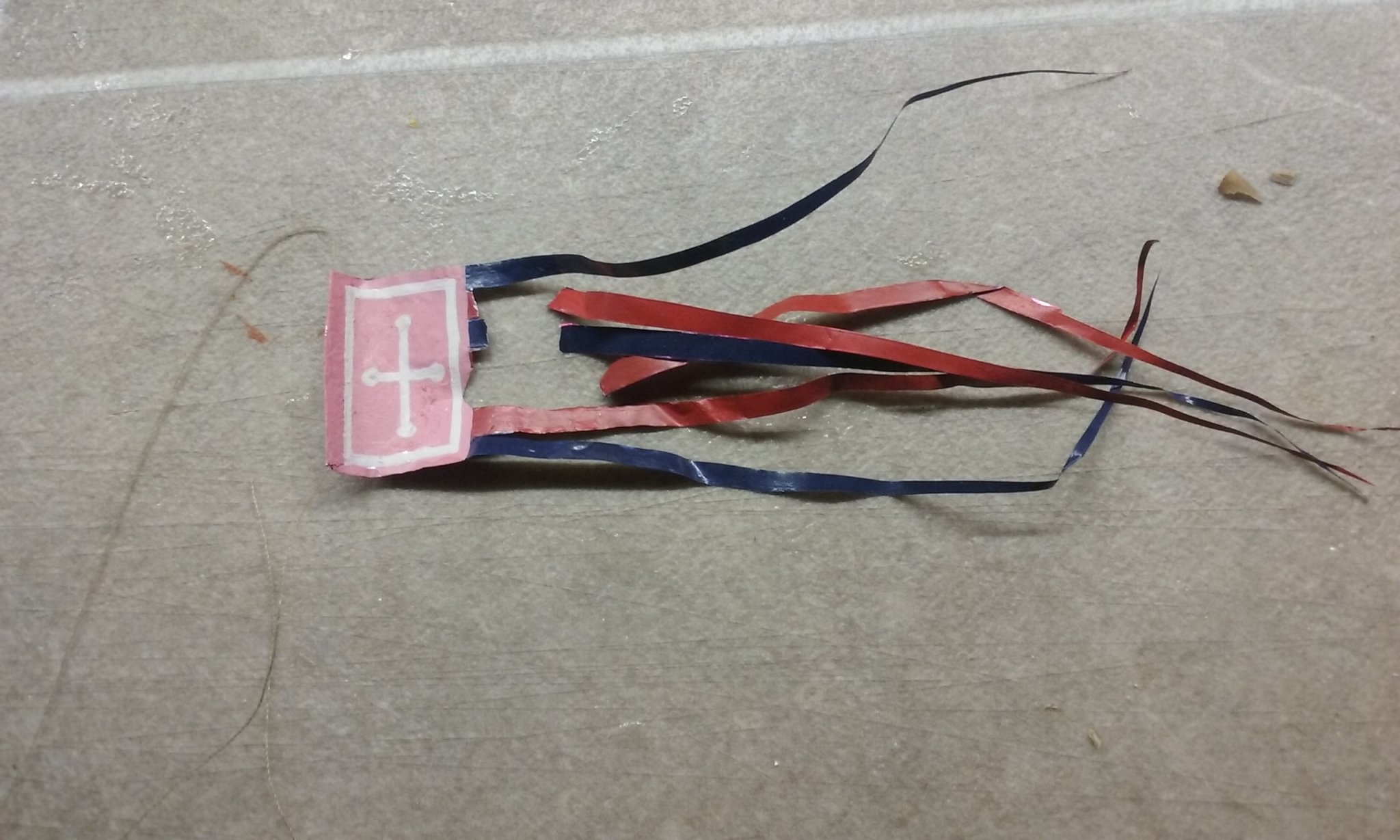
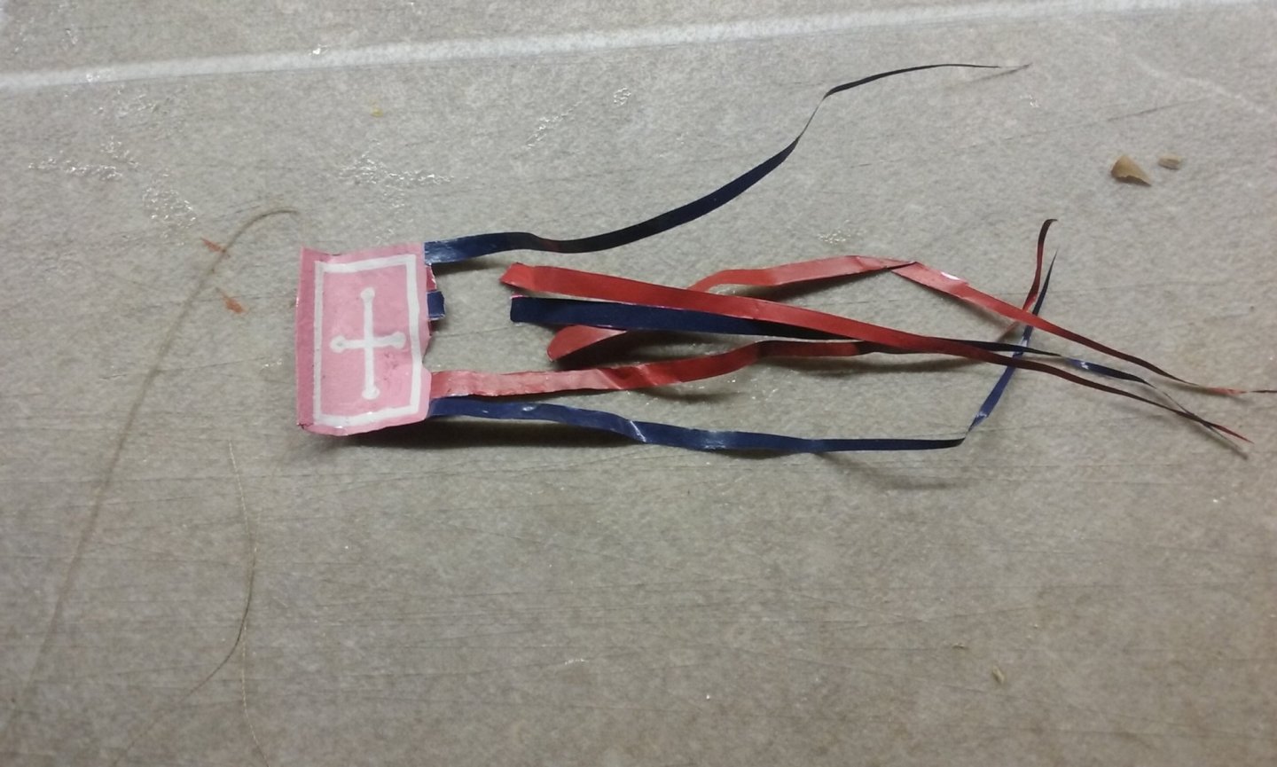
A word of warning - DON'T use the foil from Easter eggs to make flags! Here's the banner I made from the foil - see my post of June 14, 2019. Here it is now . . . It just disintegrated - no sudden shocks, no cats (or small children) involved, just broke up all by itself. It lasted only 9 months! Oh, well. Back to the drawing board . . . Steven

-
Thanks for the comment, Pat, and thanks to you and Alan of the Ship Modelling Society of Victoria for the opportunity to show the dromon off to the public. It's all very well to be pretty sure you're building a good model, but let's face it, I think we're all closet show-offs, and admiration for your 'baby' is never unwelcome. Steven
-
HMCSS Victoria 1855 by BANYAN - 1:72
Louie da fly replied to BANYAN's topic in - Build logs for subjects built 1851 - 1900
I got to see HMCSS Victoria this weekend as a guest of the Ship Modelling Society of Victoria at the Geelong Wooden Boat Festival. She is very beautiful - better in real life than in the photos. Steven- 1,013 replies
-
- 5
-
-
- gun dispatch vessel
- victoria
- (and 2 more)
-
As I read this, the revenue boats crept up on the (smugglers with) the brandy . . . Steven
-
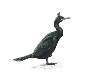
(Thinks: Aha! another steam-boat to sink!) Dangerous birds, those shags. You really have to watch out for them Steven

-
Beautiful work, Jan. Really impressive. I wonder why they had all the guns in the after half of the ship. It seems like a very strange decision. Perhaps to make better room for cargo in the fore half? Steven
-
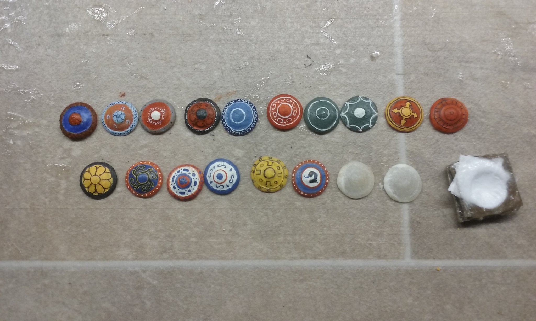
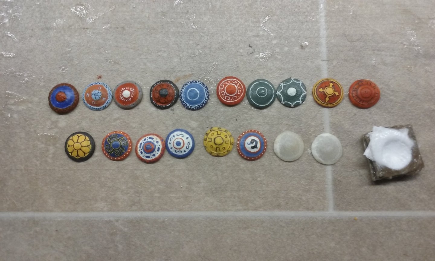
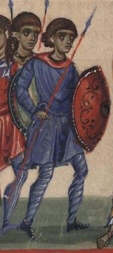
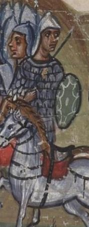
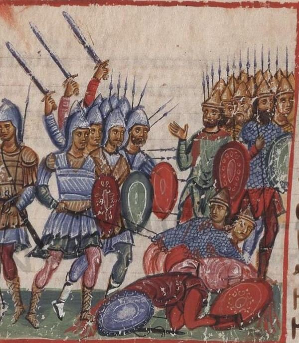
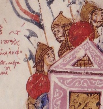
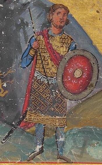
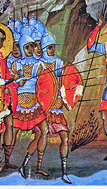
Here are the shields at the current state of production. The two on the right-hand end were painted from memory and though they're similar to shield decoration common in Byzantium, they aren't based on any particular shield in the contemporary pictures. The rest in the top line are copied from shields in contemporary iconography. The two on the bottom line aren't quite finished yet - one shield formed and cut to shape, the other still in the mould. And here are the originals: Steven

-
I've always had trouble with this myself, until I had the epiphany that I could go to google translate, type in the word in the English section, and the French translation would supply the accents. Then copy and paste into the text of my MSW post (i.e papier maché) . It even works with the Greek alphabet! (I haven't tried it with Chinese). Steven
-
Mark, I don't think there's likely to be a problem. The film of butter is very thin (has to be to get accurate detail), then after removing the shield from the mould I smear PVA over the face of the shield (i.e. the only surface that is in contact with the butter) which should seal it in pretty much, then I paint over the whole outside face with enamel paint. If bugs can get through THAT, they're a better man than I, Gunga Din. Steven
-
Thanks for the likes and the comments. Mark, I started out with a "blank" (you know the original thing the mould is cast from -don't know the technical term) made of plasticiene (modeller's clay to those of you who led sheltered lives), then cast it in a little box filled with builder's bog (car filler) - brand name Plasti-bond. When it had set I coated the inside with something greasy so it wouldn't stick and cast the "male" part into it with more of the same stuff. I found you have to be careful to make sure you don't get little bubbles in the mould - though it can be repaired. Now I'm making the shields I find that smoothing with a finger is better than using the male half - it's more reliable and gets the detail better. I've always had a bit of a thing about the thickness of shields in model ships, having (in a previous life as a mediaeval re-enactor, prior to ship modelling) used a shield myself. Too thick and they get very heavy after a while - not a good thing when you're "fighting for your life". So I spent a lot of time and research trying to figure out how to make them really thin for the model. I tried wood, tinfoil pushed into the mould with a resin backing etc etc. The tissue/PVA technique seems to work best. Steven