Louie da fly
-
Posts
7,568 -
Joined
-
Last visited
Content Type
Profiles
Forums
Gallery
Events
Everything posted by Louie da fly
-
 Glad the book was useful to you. I was impressed by how much information the author had managed to pack into such a small book. And for a change, it all seemed relevant, rather than being padded out with a lot of bumf and waffle. Steven
 -
Thanks, Druxey. If I do something like that again I probably will cut the pieces to shape. Bending is too uncertain. But I wanted to try it out - hubris, I suppose. I've kept an eye out for those plastic-covered clamps you asked about. No joy so far, but I'll keep looking. By the way, I looked up "rubbing alcohol" and apparently what it is depends on where you are - in the US iso-propyl alcohol is called rubbing alcohol. Elsewhere (as in the UK) it's ethanol ("drinking" alcohol) with about 5% methanol (wood alcohol) to make it undrinkable - otherwise known as methylated spirits. Best served cold from the fridge . Which one is it you use to get glue off? Regards, Steven
-
Hearns hobby shop under the arches at Flinders St Station in Melbourne - down Flinders St walking away from Swanston St. I think it's still there, and might have the figures you need, intended for model railways. As Kurt says, "O" gauge is 1:48 - close enough to 1:50. Maybe you could phone them and find out (saves you a trip to Melbourne if they don't). Steven
-
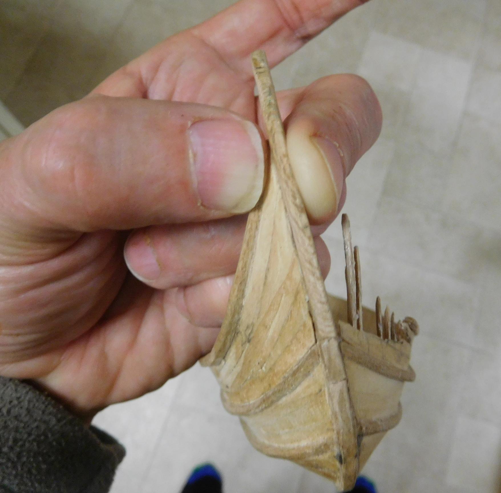
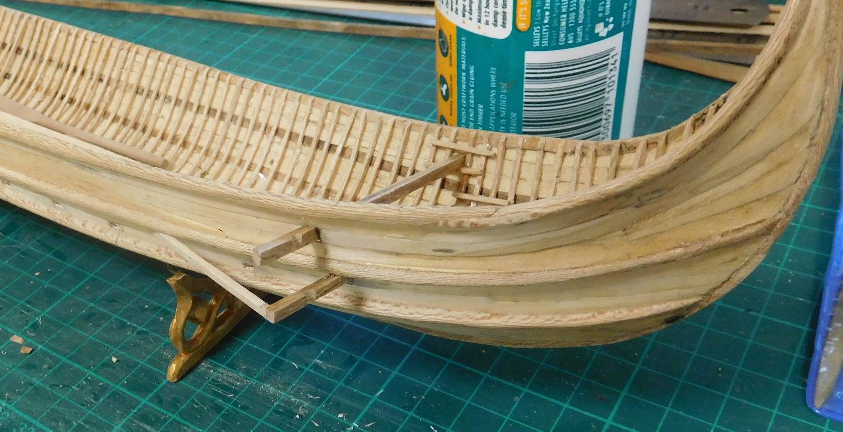
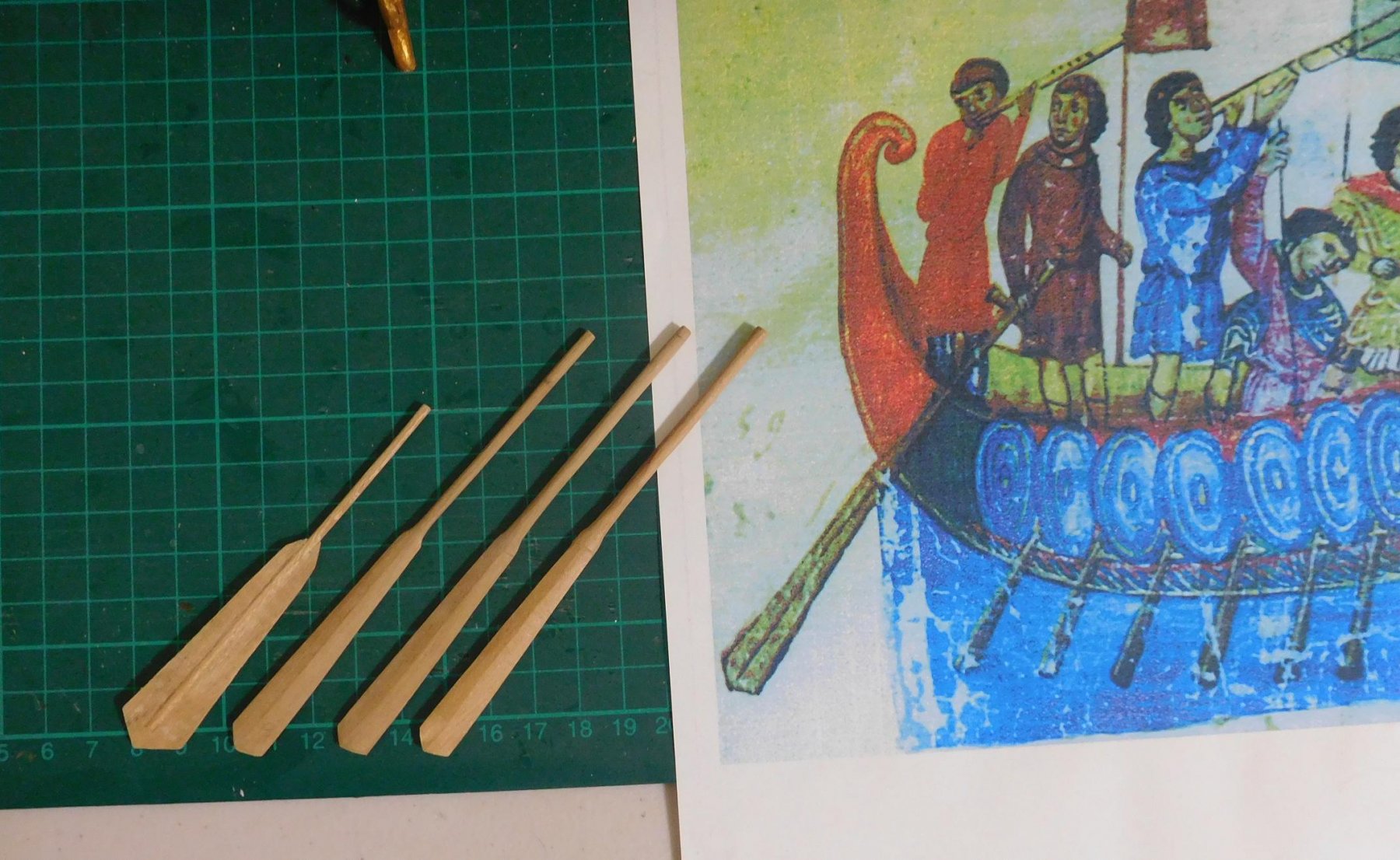
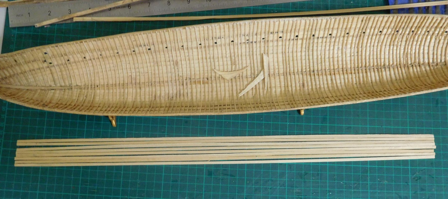
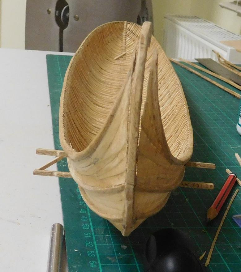
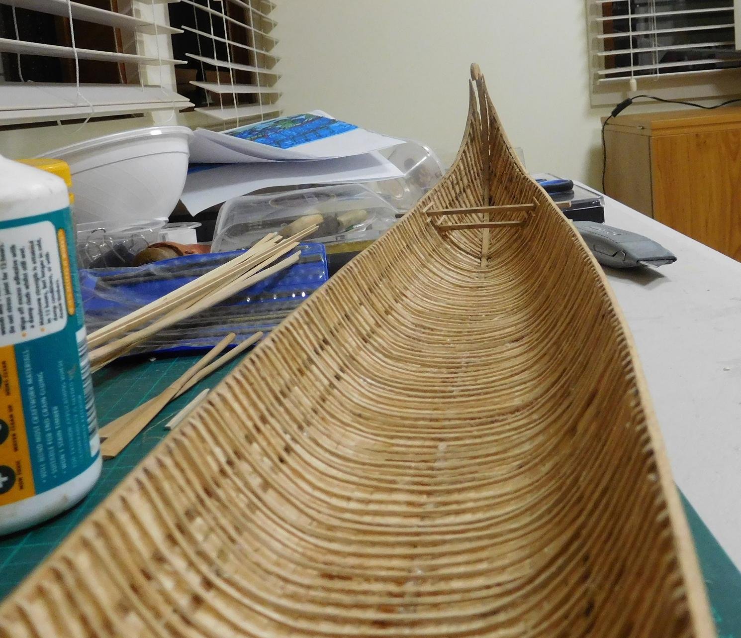
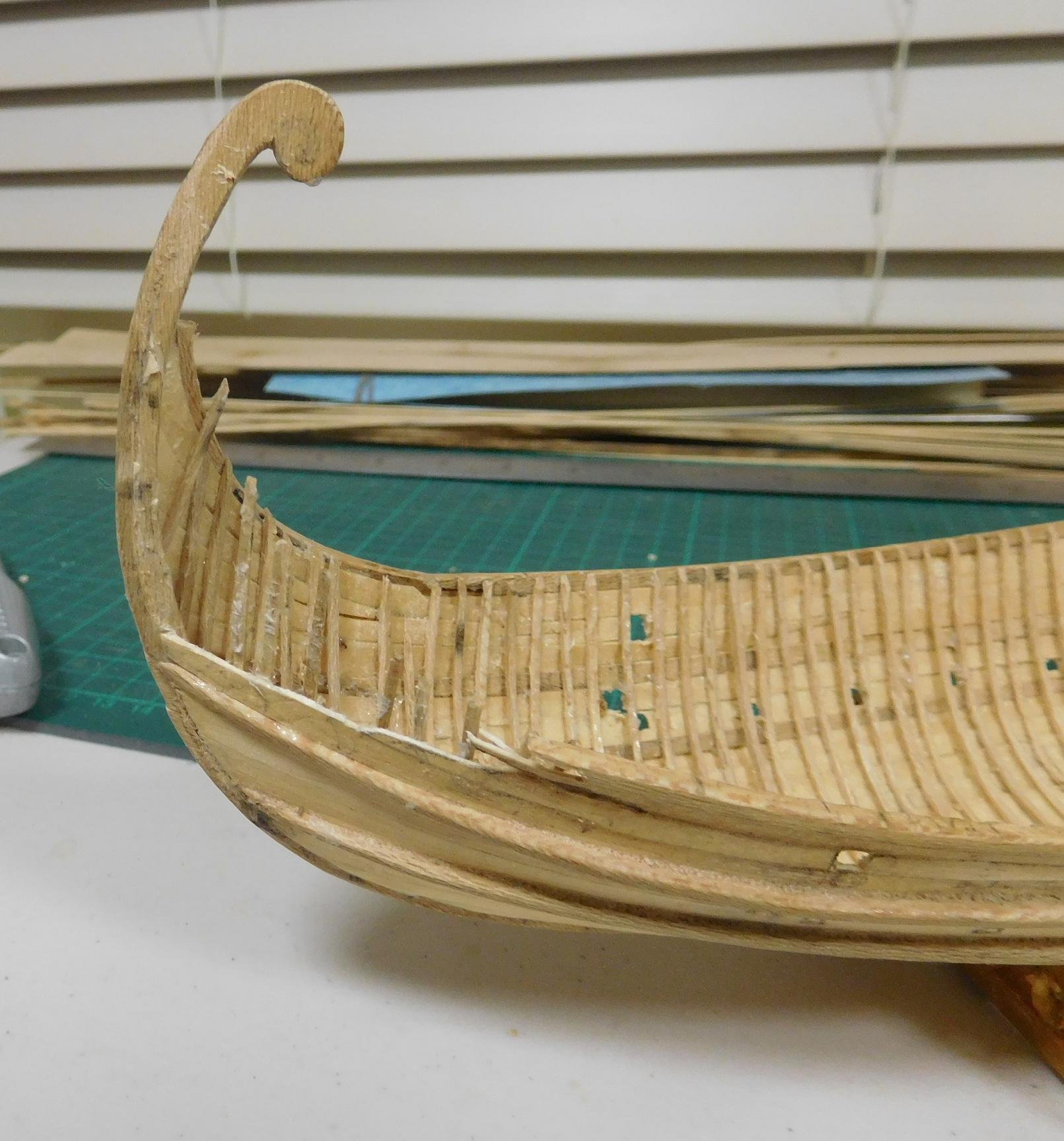
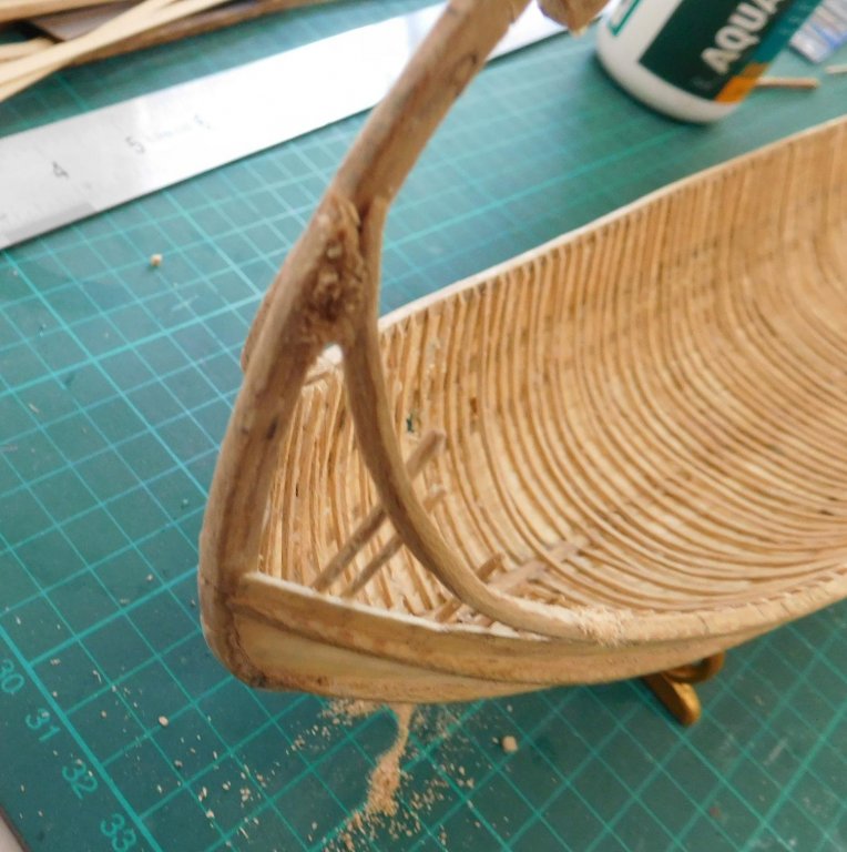
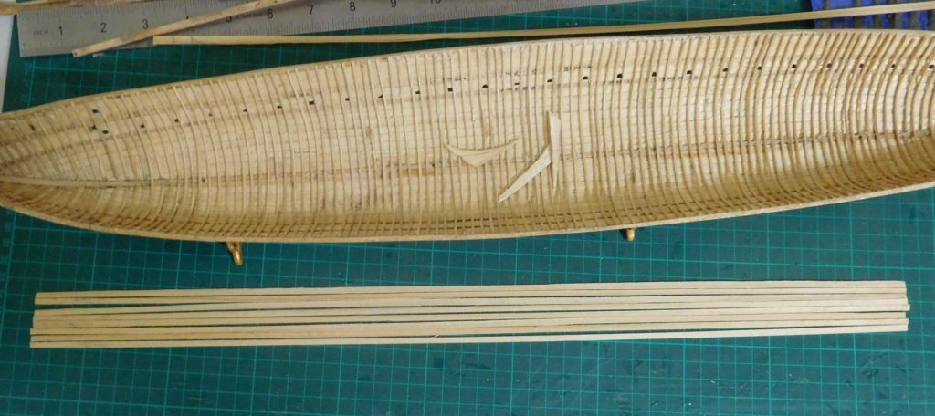
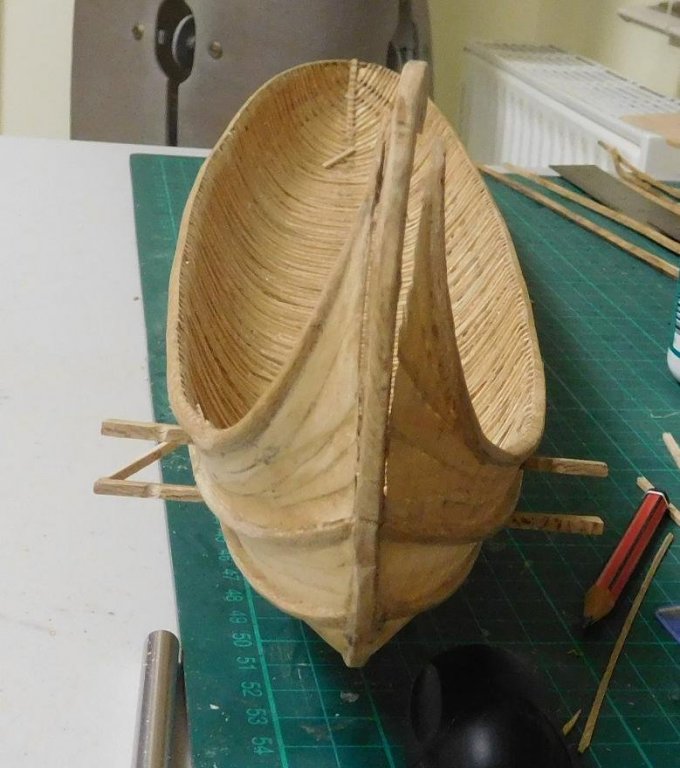
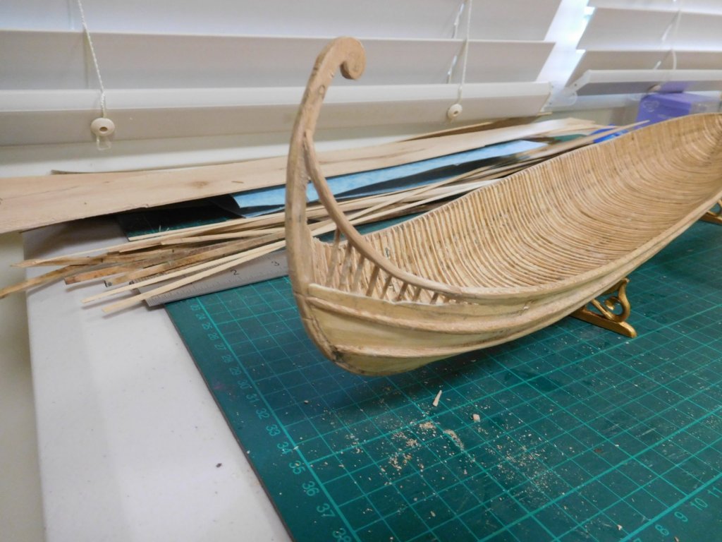
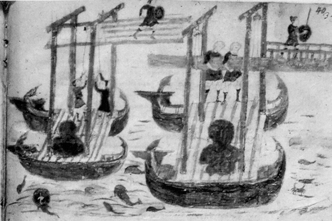
I’ve been away for a while – life’s been getting in the way. But I haven’t been idle; there’s been slow but steady progress, though a little erratic. I put in place the through-beams for the steering oars and began on the support structure . . . And then - DISASTER! The extensions to the gunwales that formed the tail of the ship had been shaped by heat bending, and when I put them on I didn’t realise they were exerting a sideways force on the sternpost. On a routine inspection I discovered they’d pushed the sternpost into a quite dramatic curve to starboard - and the tail planking was following the off-centre curve. It took a week to decide whether I should correct it, with the chance of completely stuffing up the whole ship – the frames and planks are very delicate - or leave it as it was and have it sneer at me for the rest of my life. In the end I took my courage in both hands and started pulling it to bits – with horrible memories of what happened when I decided to re-do the Great Harry model – it’s still waiting for me to rescue it once I’ve finished this one. I should have taken a “before” photo to show how bad it was. But I at least got some directly after I’d cut both sides away from the sternpost, which gives a fair idea. I’d thought I’d have to put the ship back on the plug to have a stable base for the repairs, so I removed the through-beams and the partly completed steering structure as well. It turned out I didn’t need to use the plug, but removing the through-beams has made it easier to put in the stringers (see below), so it wasn’t a total loss. Fortunately the port side wasn’t too bad, and the sternpost came almost back to its correct shape once it was cut free. But I had to take off quite a bit of the planking on the starboard side. And the “tail” of the starboard gunwale. It turned out that the residual bending in the port gunwale and the sternpost cancelled each other out, and i was able to bring it all back into square by squeezing them together. I didn't have a suitable clamp so while the glue dried I just held them together with my fingers. And it's now about as straight as it can be. A tiny bend in the head of the sternpost, but it's almost invisible and I've decided I can live with it. I’d been worried I’d have to make a new pair of “tails”, but I was able to re-use them with a minimal amount of tweaking, and re-position them so they didn’t push the sternpost sideways. I’m pretty happy with it now - it’s nice and straight and as the off-centre forces have been removed I’m satisfied it won’t happen again. But the starboard “tail” was now about 3mm (1/8”) too short, and I had to use filler to make it good at each end. While under repair it looked pretty ghastly, but I’ve finally got it to a point where it only needs a bit of planking and it’ll be right as rain. Another learning experience. Sigh. By the way, having finalised the steersmen’s positions, I realised the handles of the steering oars were way too short. Serves me right for making them too early. As I was going to have to re-jig them, I thought I’d have another look at the 11th century picture I got the design from. Not good, I’m afraid. The rudders I’d made didn’t look much like the original at all. So I might as well be making completely new ones. Below are the steering oars, with the contemporary picture for comparison – from the left, one of the original pair; then the first new one, carved out of pear wood (which I discarded because although the shaft was the same thickness as in the picture, it looked too thin for the forces involved in steering a ship of this size); and the last two are my final version. I still have to put the tillers (visible in the picture) on them. I’ve also made a bunch of stringers, based on those found on one of the Yenikapi galleys. Only two of the galleys found had stringers. One had only a single pair, each made from half a youngish tree split down the middle, and placed face down at the turn of the bilge. The other had four stringers each side of the keel, made of planks the same thickness as the strakes of the ship (about 25-30mm, or one inch), and 150mm (6”) wide. Though the first configuration did seem attractive, I decided to follow the second. Here they are: And here is the first one in place at the turn of the bilge. There’ll be another three between this and the keel on each side. And here it is bent to shape. I didn’t have clamps that reached far enough to hold it in place while the glue dried, so I acted as my own set of clamps. Only seven to go. Steven


-
Hi John, Did you end up getting that book? You're making good progress so far. I'm looking forward to seeing it taking shape. By the way, us Aussies probably have no more idea of Maori culture or artefacts than you do. Our own aboriginal population are completely different racially and culturally, with totally different origins. Ask us about New Zealand cricketers, and we'd probably be able to answer. Steven
-
There are quite a few galley (bireme, trireme) build logs here and in the scratch build section which might be of use to you as you make your model - sometimes when you encounter a problem, someone else has already solved it in their own build. I'm pretty sure there's at least one Amati bireme amongst them. 55cm - that's a respectable size. Good luck with it! Steven
- 122 replies
-
- 1
-

-
- greek bireme
- scale-1/35
- (and 2 more)
-
Ancient shipwrecks found at the bottom of the Black sea
Louie da fly replied to Baker's topic in Nautical/Naval History
Wonderful stuff. I'm looking forward to the archaeological reports (though that won't be for a number of years, as they sift through all the information). This is a fantastic find for those of us interested in mediaeval and ancient ships. So many questions waiting to be answered! Steven -
It's well worth going. I had to go 12,000 miles to get there, but you're within coo-ee of the place. But then, there's so many worthwhile places to see in the UK. It's hard to see them all in a lifetime (let alone a three week visit). We went in 2009, the 500th anniversary of Henry VIII coming to the throne, so there was a huge amount of stuff laid on especially to see for those interested in that sort of thing. But the Mary Rose was inaccessible - they had just started building the new enclosure and nobody was allowed near it. On the other hand, the collection of artefacts was increased greatly, so we got to see shoes, a fiddle, wrought iron swivel guns, a parrel truck etc etc . . . (We also went to Bristol to see the Great Britain, and were lucky enough to see the Matthew reconstruction while we were there - carrackly goodness!) Steven
-
Well, that's news. I didn't know about this picture's Victorian connection. I thought it was done in the 17th century. The Embarkation at Dover is still in existence. It's on a wall in the Wolsey Room at Hampton Court Palace. And the painting of the actual tournament at the Field of the Cloth of Gold is at Hampton Court as well. The mural in Cowdray House depicted the sinking of the Mary Rose. The Great Harry is in the picture as well - there's a reasonably good Victorian copy of the mural, but it's infuriating to think some of the strange details in it may simply be copyist error, not original features. By the way - though the Great Harry was one and a half times the burthen of the Mary Rose, she wasn't much bigger to look at - only about 1.145 times as long - because she was 1.145 times as long, and as wide, and as deep (1.145 x 1.145 x 1.145 = 1.5). Steven
-
Thanks everyone for the likes. Thanks for the info Druxey. I'll try the rubbing alcohol and see if it does the job. I've been using white glue (PVA). I'll have a look for those bulldog clips. I don't think I've ever seen them before. On reflection I think I'll have to move the transverse beams back just a little, to make sure there's no clash between the side-rudders and the aftermost oars. Steven
-
This is neither by Holbein nor is it the Great Harry. It's a ship from considerably later. There are in fact two contemporary pictures of the Henry Grace a Dieu, one by Anthony Anthony and the other by an unknown painter, showing her with sails painted to resemble cloth of gold. I think both are shown in my own stalled build (see signature below). She should in fact look very much like the Mary Rose - they were built - and rebuilt - at pretty much the same time - the Great Harry was about one and a half times the size of the Mary Rose. It's a shame this picture in the NMM is still wrongly referenced. Steven
-
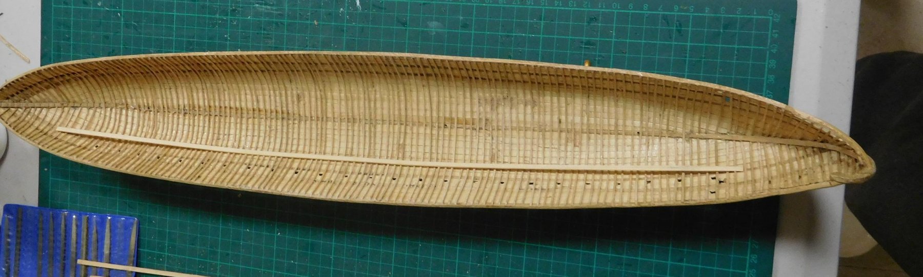
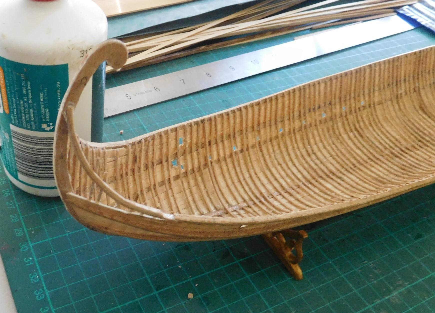
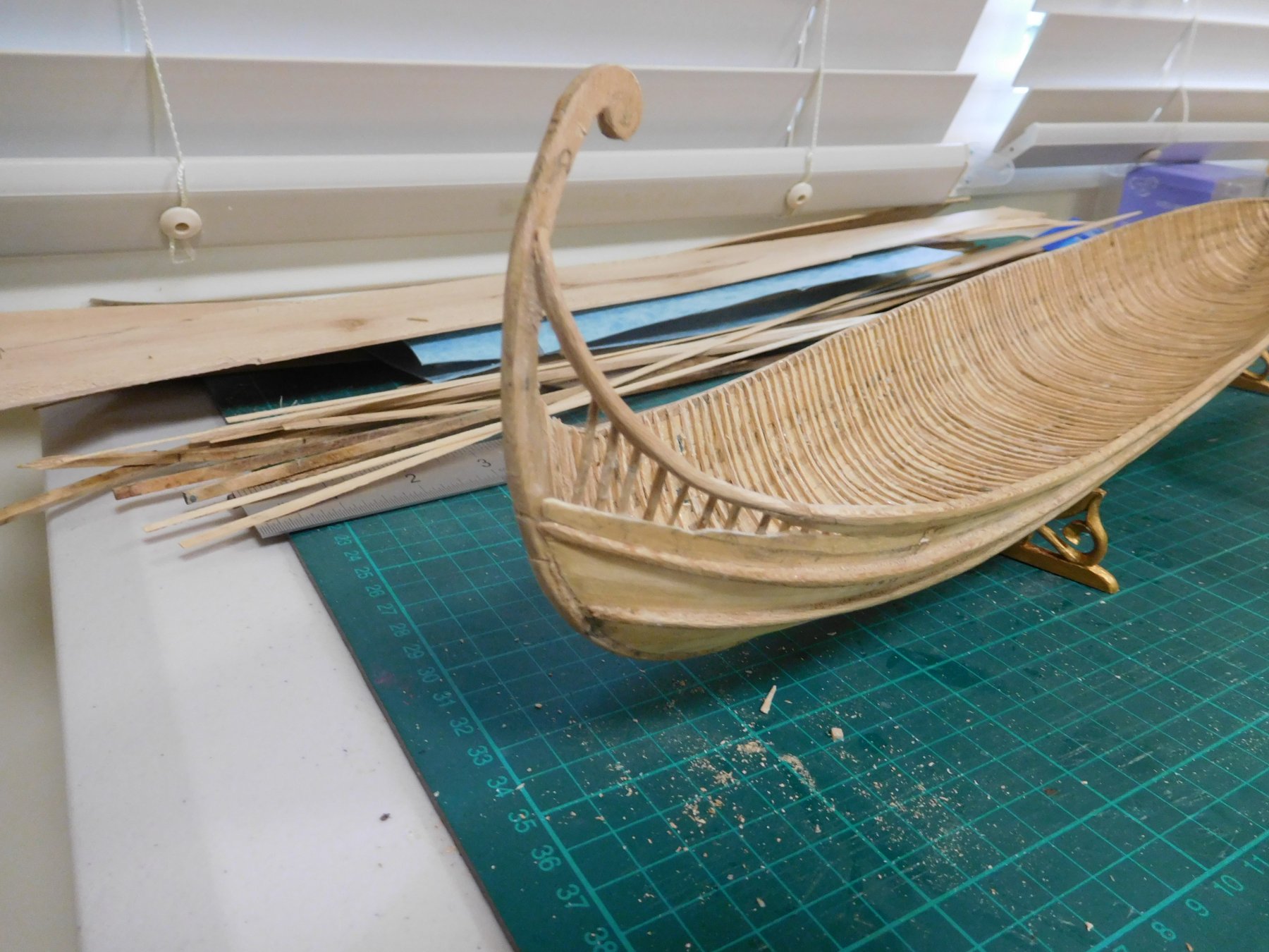
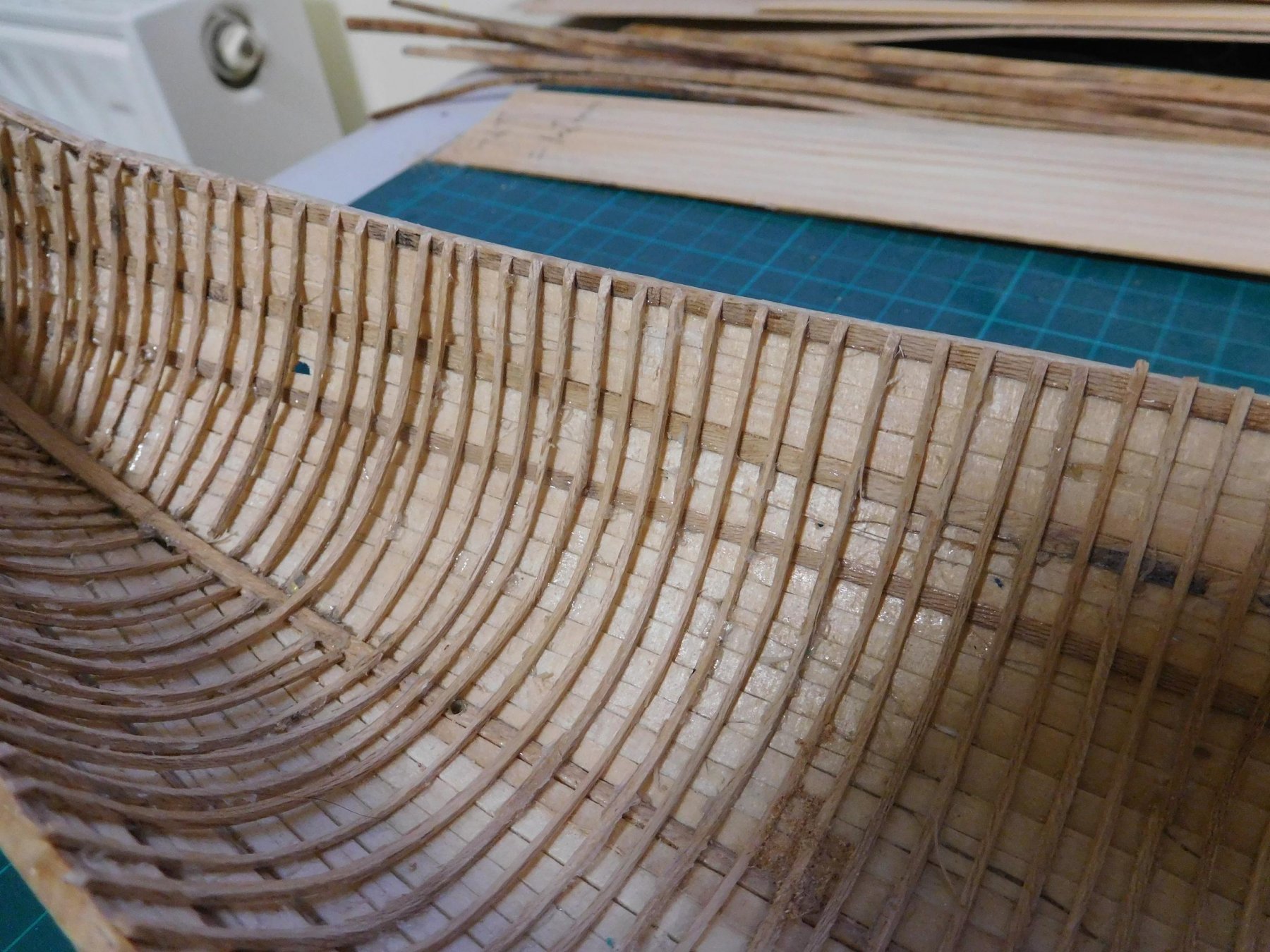
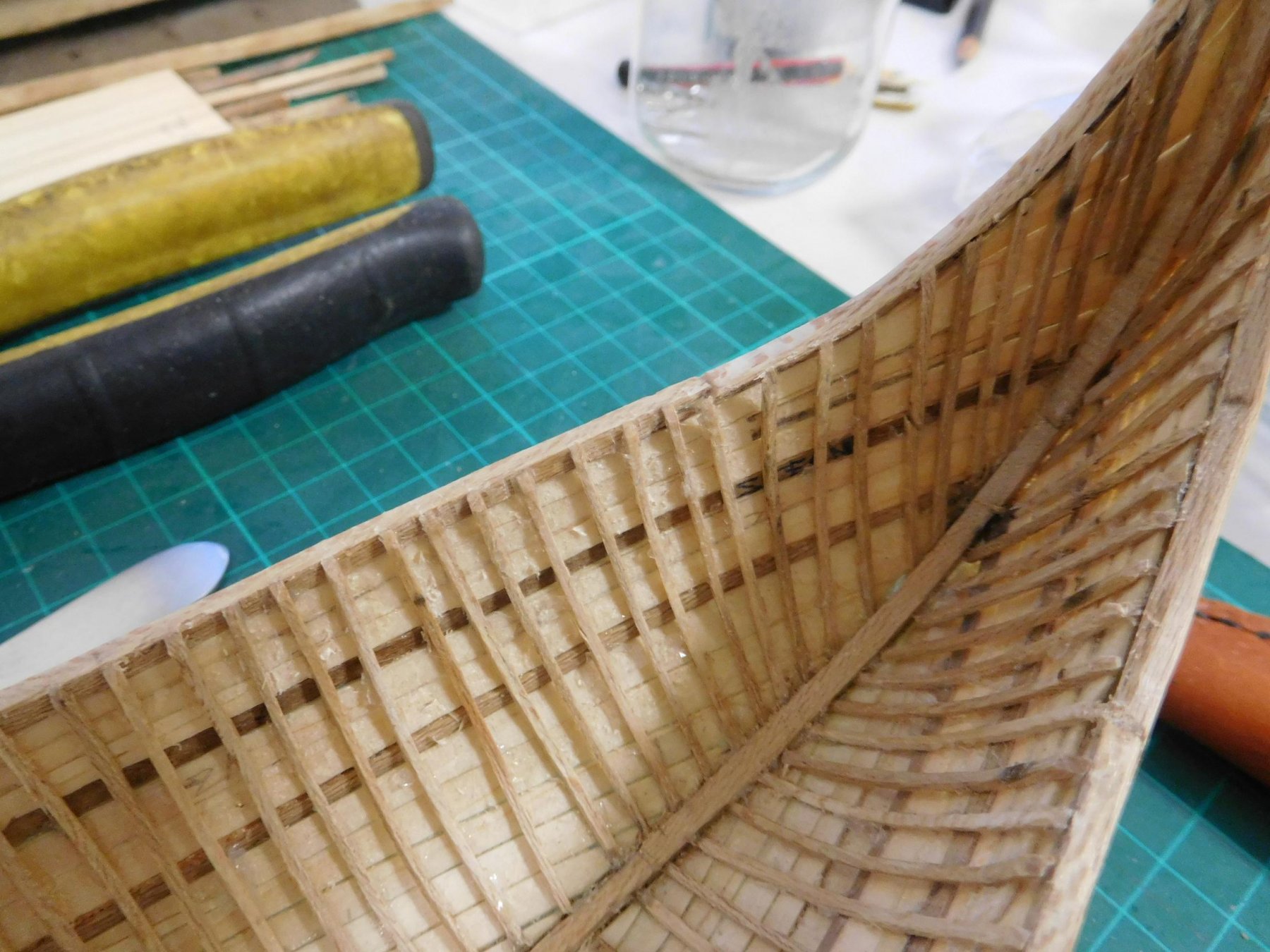
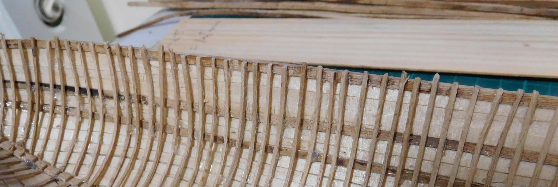
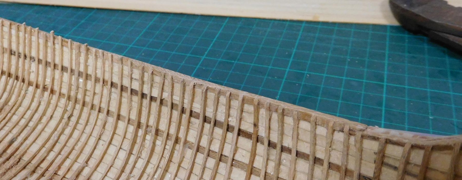
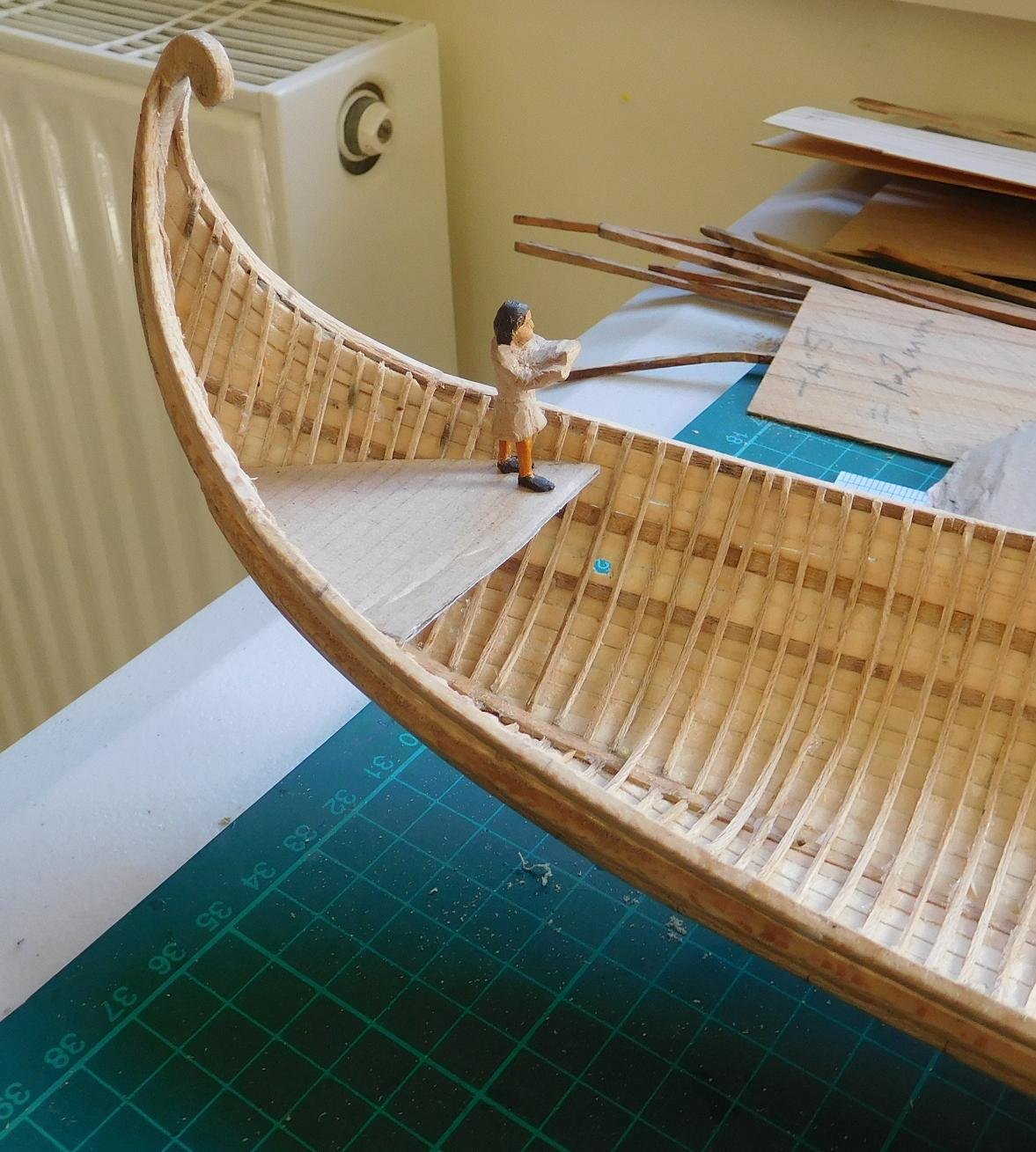
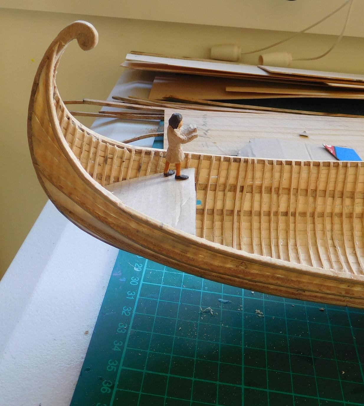
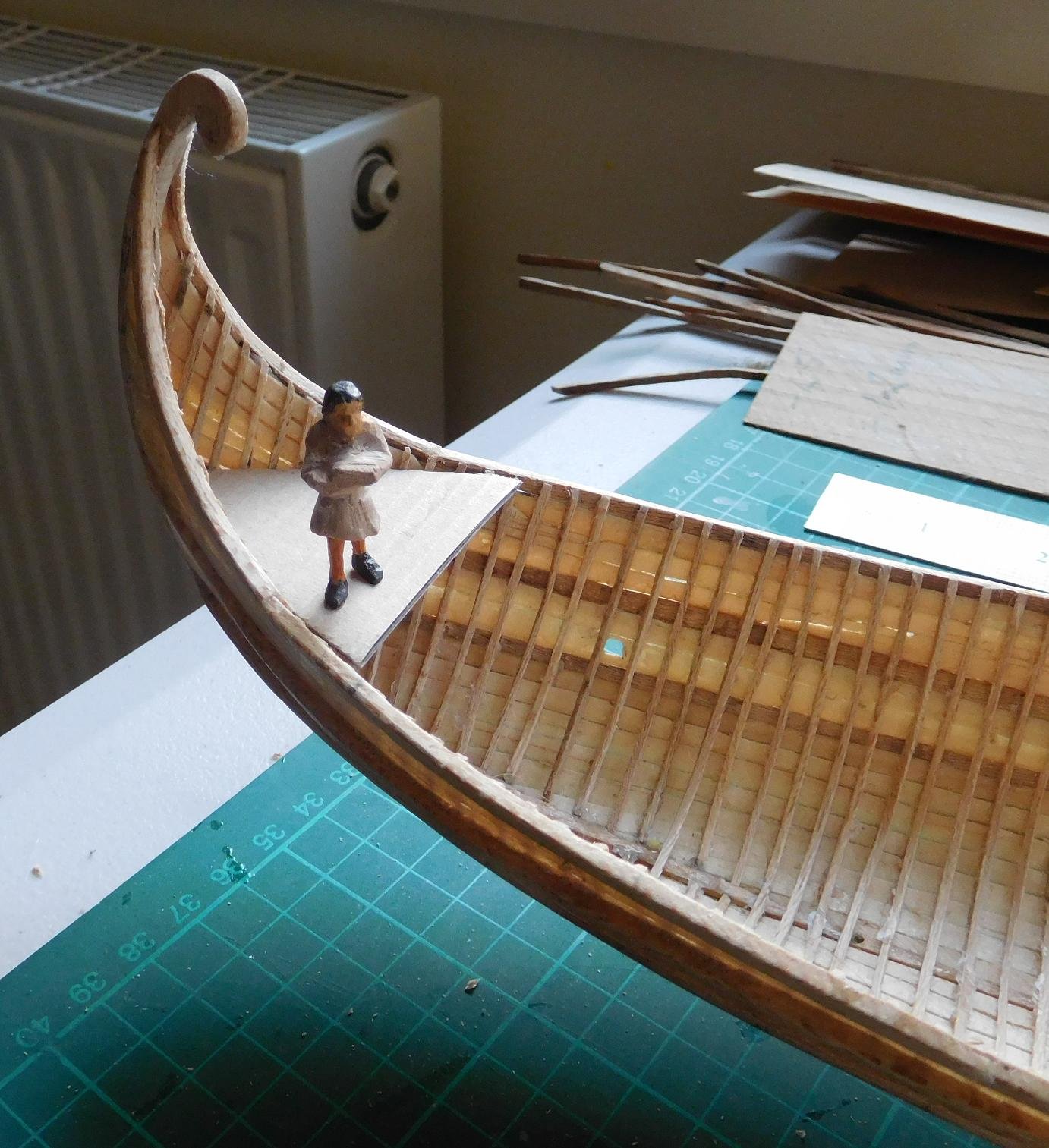
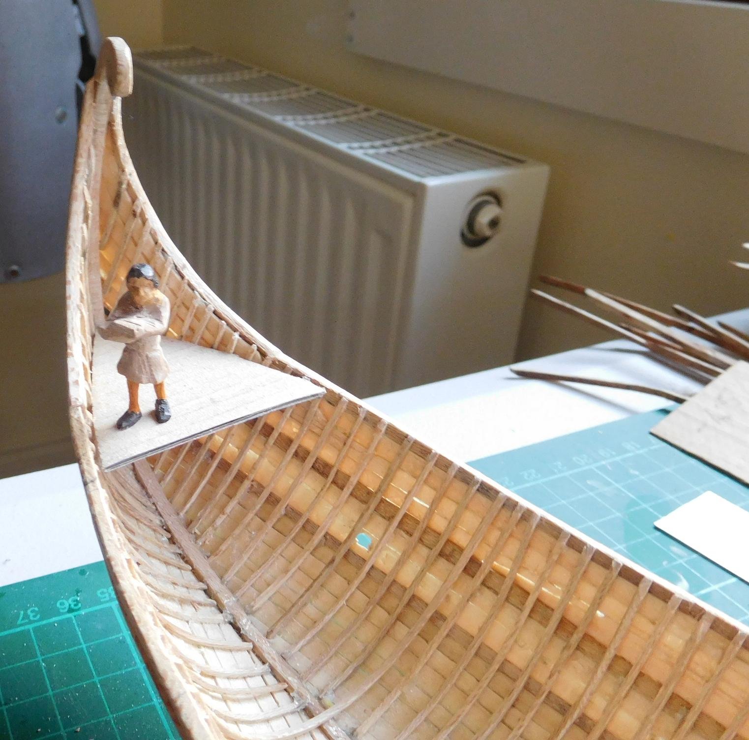
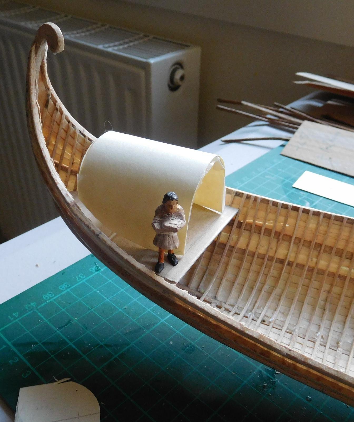
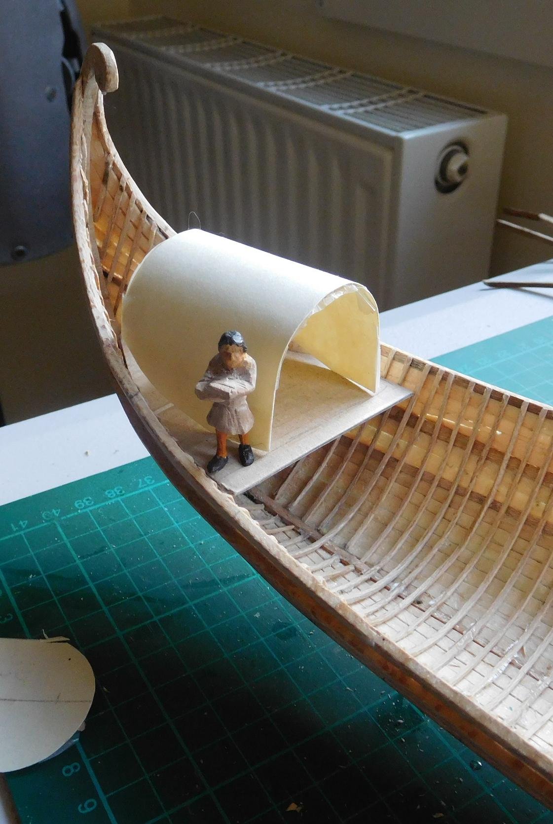
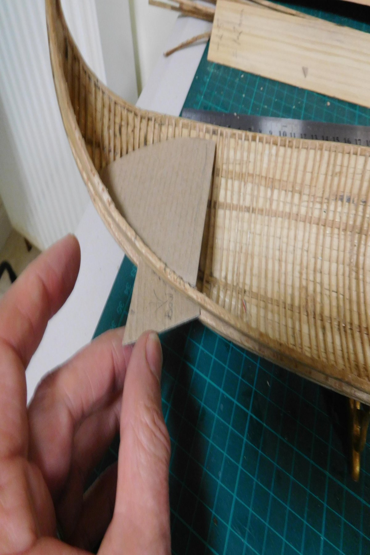
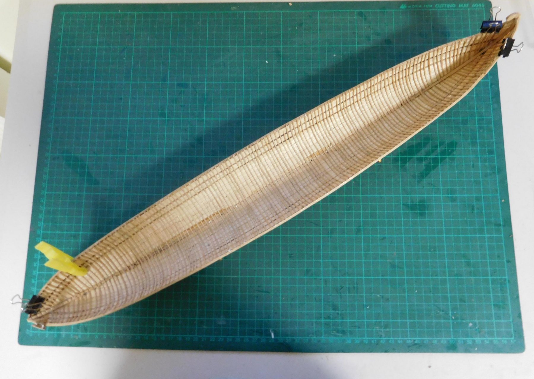
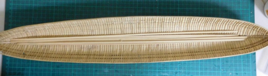
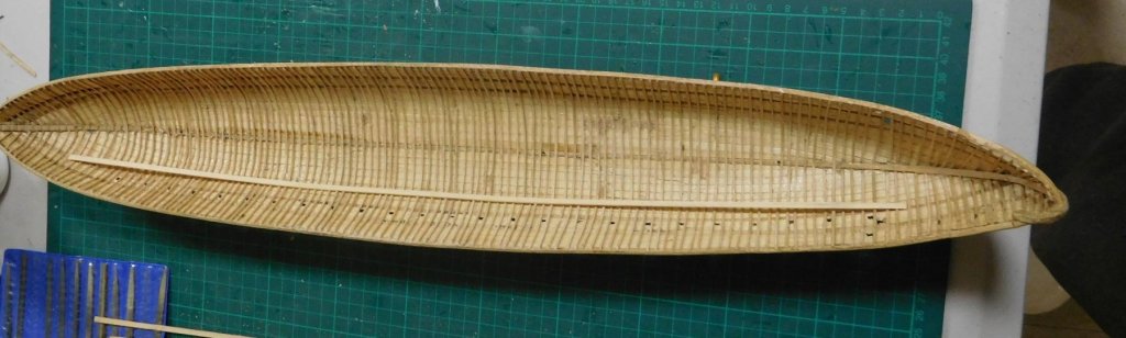
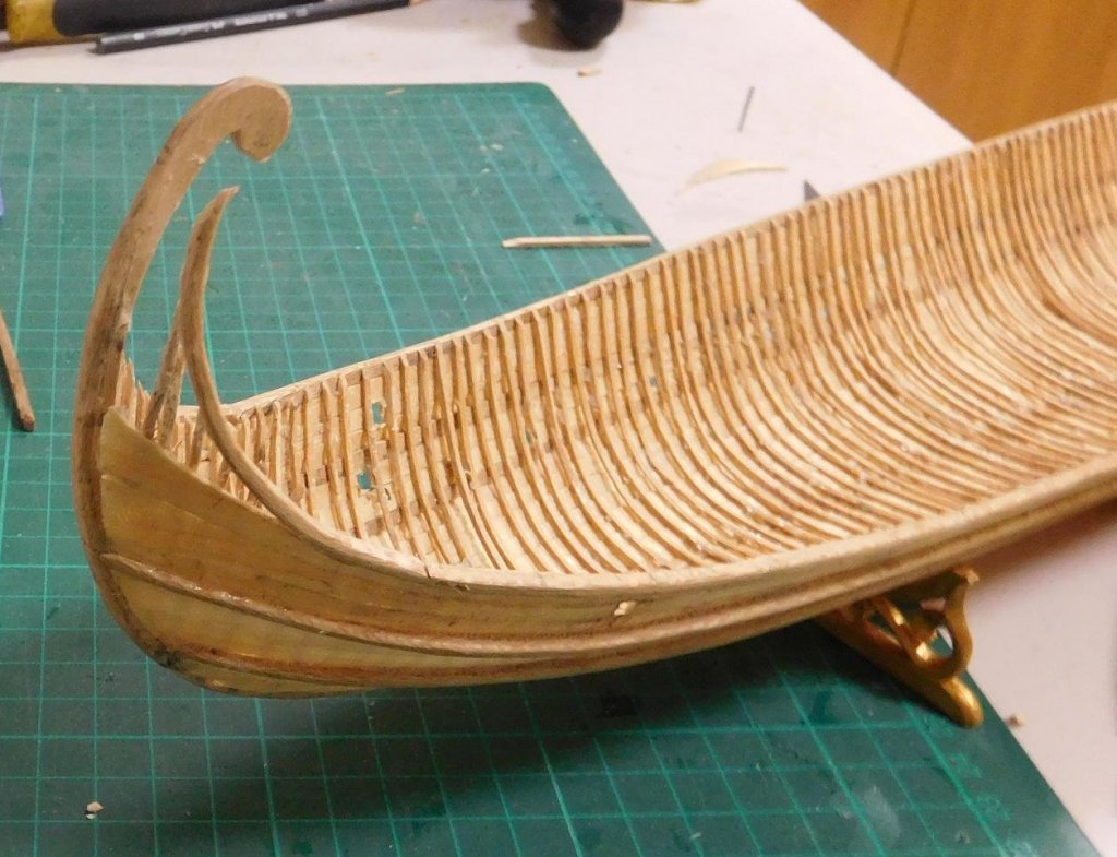
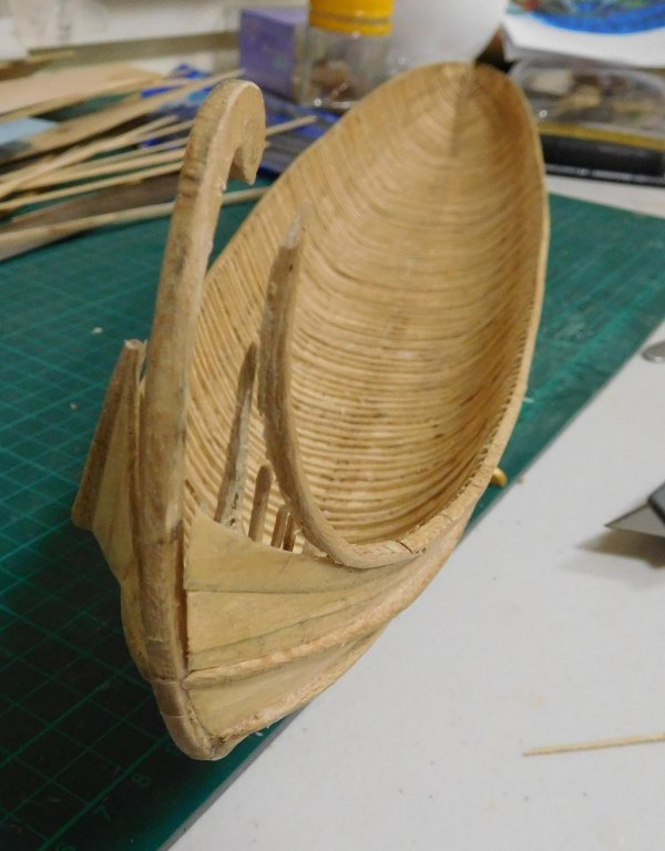
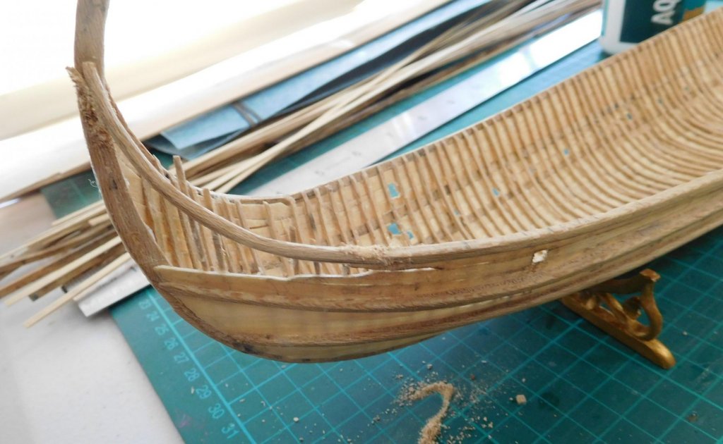
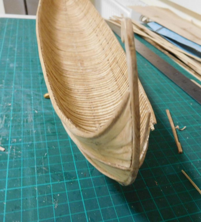
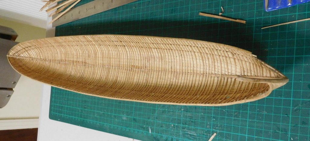
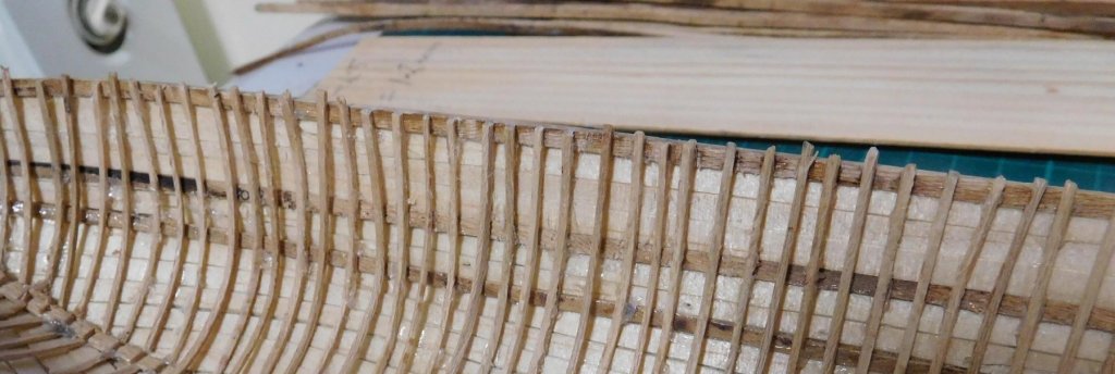
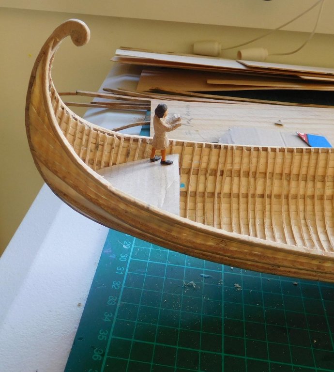
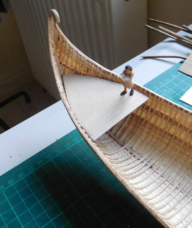
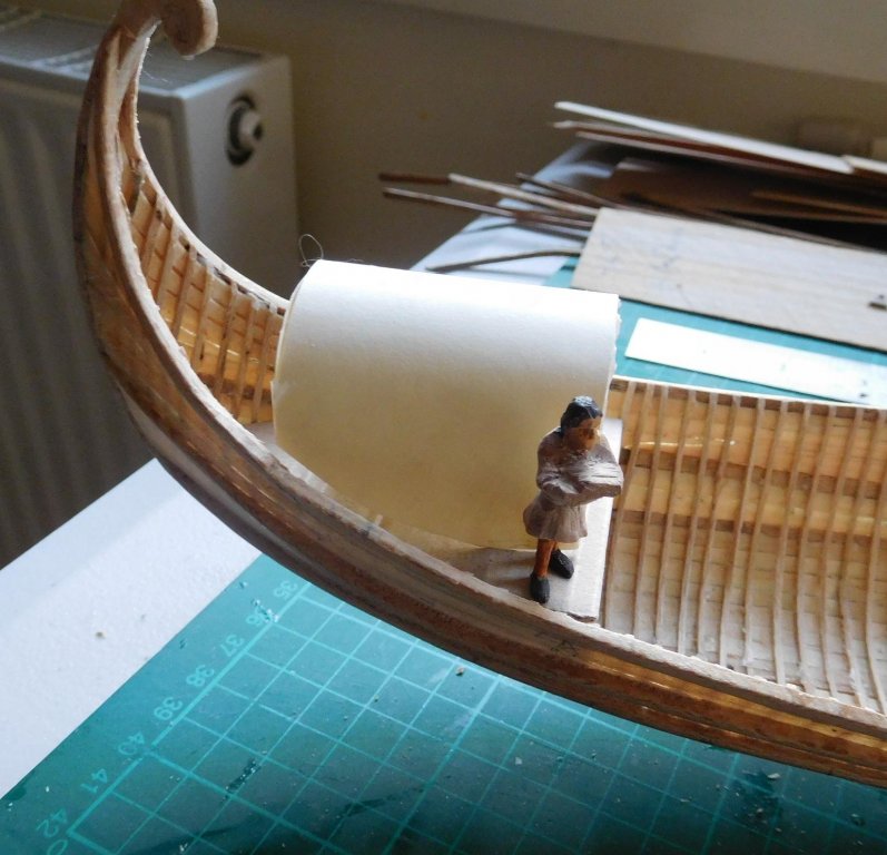
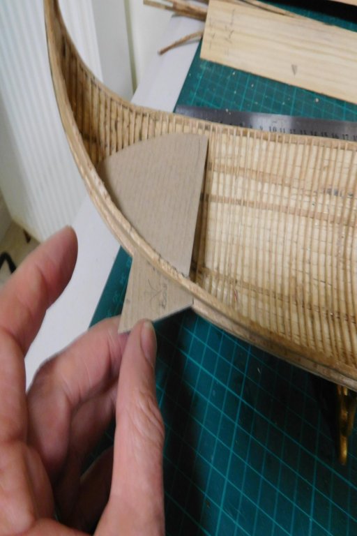
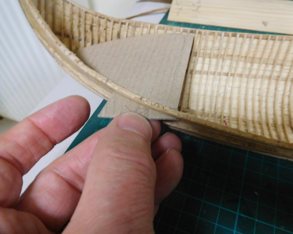
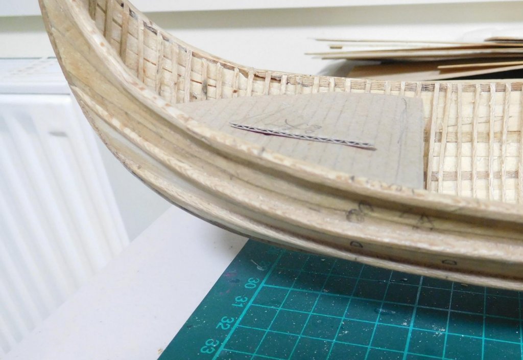
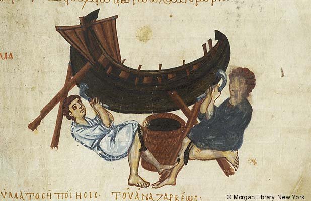
I've been doing some trimming and tidying up. I've gone back over the frames and straightened the majority of the crooked ones. I still have a couple to do, plus restoring a few which had the ends break off. I'd made an initial cut of the ends of the frames (with a big pair of cutters), but they were still sticking up a little past the top of the gunwale. First I tried cutting them off square with a scalpel blade, but this was very laborious and slow (the blade REALLY doesn't like doing it). Then I got out my trusty fretsaw blade (broken off short so I could hold it between my fingers) and that worked more quickly, but it was still a pain in the neck. But then I bethought myself that I should look back at the archaeological remains of the Byzantine galleys found in Istanbul, and it turns out the frames are actually cut off on the diagonal. This turned out to be MUCH easier to do just using the scalpel. Took a few hours to cut them all off (132 of them) so they looked neat. Unfortunately, as can be seen above, the amount of glue that sneaked in past the plug and the cling wrap is still something of an eyesore. I've decided to ignore anything that won't be visible in the final model (hidden by the deck, for instance), but I still have more work to do getting rid of the vestiges that will be in plain view. I've used the scalpel to get the worst of it off, but now the surface is rough from the scalpel blade and still looks pretty ghastly, so I need to have another go at it, perhaps by scraping or sanding. I've been experimenting with cardboard cut-outs for the prymne (poop deck). It has to be big enough for the captain (or at a pinch the Emperor and a few of his courtiers), with a tent for shelter, plus two steersmen. The first one I made, which was the size I'd drawn originally, was far too small - it would barely have room for the steersmen. The second was better, but really still a little inadequate. Finally, the third seems to be big enough for the purpose - there should be room for a reasonable number of people, a tent and the steersmen. I'll have to extend the tent as my cardboard cut-out doesn't go far enough back. I'm thinking of having the side walls rolled up so you can see the people inside. Using this final form of the prymne, I was able to work out where the steersman would stand, and so where the steering oar would pivot against the hull. Then, using as my basis an 11th century Byzantine picture of of a hull being scraped (or possibly caulked), I started working up a shape, size and position for the structure protecting the steering oar mechanism. There are certainly other shapes for this structure (mostly rectangular) but this one appeals to me. I note also what may be two periboloi (catheads) at the bow. I'd been wondering what shape they might be, and this picture may answer my question. And are those tholes sticking up from the gunwale? The first protective structure I made was too big and the not quite the right shape. Going back to the picture I made a another one that looks right when held against the hull. If you look carefully you can see a line across the gunwale and the word "pivot" about level with the centre of the triangle. There will be enough space between the poop deck and the main deck below it for the two transverse beams that will support the steering oars. I've marked their approximate position on the hull with circles as can be seen in this photo. Below them you can see semicircles accurately marking the final positions and size of the oarports of the lower bank. They are four frames apart and I've made sure they won't clash with any the frames. Steven


-
Interesting what you see even when something is really familiar to you . . . After years of looking at the ship with the Greek fire, I've only just noticed that she has what are almost certainly TWO banks of oars! So she IS a dromon! Steven
-
According to the thesis by Mark Geanette (Mast Step and Keelson: The Early Development of a Shipbuilding Technology) mediaeval Mediterranean lateeners didn’t have a separate mast step. The keelson performed that function, being fixed more firmly to the keel where the mast was, as can be seen in the 11th century “glass wreck” of Serce Limani. Now that it’s almost time to put in the keelson I need to start thinking about whether the dromon should have one or two masts. Unfortunately, the available evidence is equivocal – some points to a single mast, some to two masts. One Mast: 1. When writing of dromons, Leo VI in his Navmachia Leontos Basileos (On Naval Warfare by Emperor Leo) refers only to “the mast”, never “the masts”. 2. The inventories for the Cretan expedition of 949 have survived, and they specify that for the 20 dromons of the fleet, 20 chalkisia (masts with sheaves at the top), 20 psellia (“rings” - probably some equivalent to parrels) and 20 sails must be supplied. 3. The only contemporary picture of a Byzantine warship with mast raised (the well-known picture from the Skylitzes Chronicle) shows a single mast. As it is using Greek fire, it’s almost certainly a dromon. Interestingly, the mast seems to have sheaves at the top. Two Masts: 1. An 11th century Byzantine document on siege warfare in the Vatican library (MS Vat. Gr. 1605 fol 40r) contains a contemporary picture of flying bridges being used to attack and cross the seawalls of an enemy fortification. These bridges are supported by two ships lashed together, each with two masts (see picture). It seems unlikely that without the support of a second mast a bridge of this sort could be kept from sagging forward too far to be of use. In his definitive book Age of the Dromon, Professor John Pryor has come down in favour of two masts, on the basis that a single mast would be insufficient for a vessel of this size, which would luff up and be uncontrollable. I’m not an expert in the balance of forces involved in the mechanics of sailing, but there are any number of contemporary pictures of galleys even larger than my dromon, with only a single mast and sail. They date to the 16th century, not to the 11th, but I don’t believe there would be any difference in the sailing capabilities of a 16th and 11th century galley. If anything, because the later galleys had up to four or even five men to an oar, their crews were considerably larger, increasing the weight of the later vessels. There is other evidence, but it’s also either confusing or equivocal. One quote (in Greek) from Leo VI text refers to a wooden castle “around the middle of the mast”. Though this initially sounds like a fighting top, galleys fought with their masts lowered, so it can’t be. On the basis that this passage was wrongly transcribed by the copyist, Professor Pryor suggests that with only slight alteration it could be read as “around the middle mast” or “around the middle (i.e. half way between) of the masts”, or “around the mast of the middle” (a term used to describe a mast shipped amidships, no matter how many masts the ship had.) The first two would mean the ship definitely had more than one mast, and the third could also be interpreted that way. But there is another possible “correction” – “in the middle, around the mast”, which takes no more liberties with the original Greek than the other three passages. Though most of the information above suggests a single mast, I’m leaning towards two, but I’m not certain – the evidence is just too indefinite. But I like to think of my dromon under both sail and oars, before the wind, with the two great lateen sails “goose-winged” – one to starboard and the other to port. Any comments or suggestions would be very welcome. Steven
-
I realised I'd lost track of this build and was wondering what had happened to it - I was enjoying it very much. I hope Glenn gets the opportunity to get back to it eventually. It's a beautiful model and a fascinating build. Steven
-
Hi Dan, Did this ever get finished? It was looking so good, and then just seemed to vanish off the radar. It'd be nice to see photos of the completed build if they're available.
-
That's wonderful, Jack. Thank you for your help. Best wishes, Steven
-
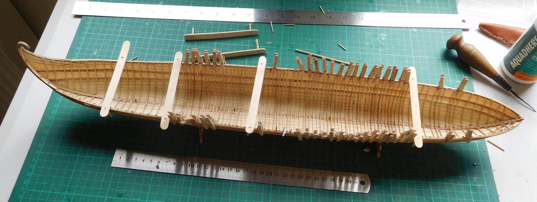
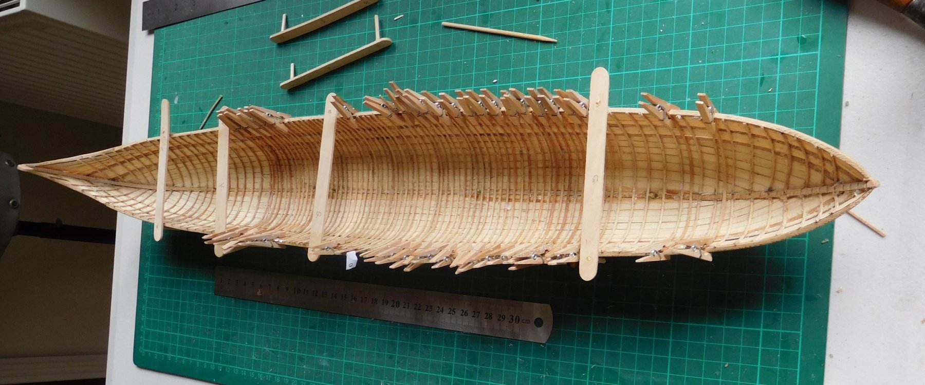
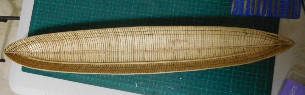
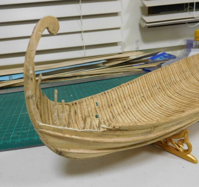
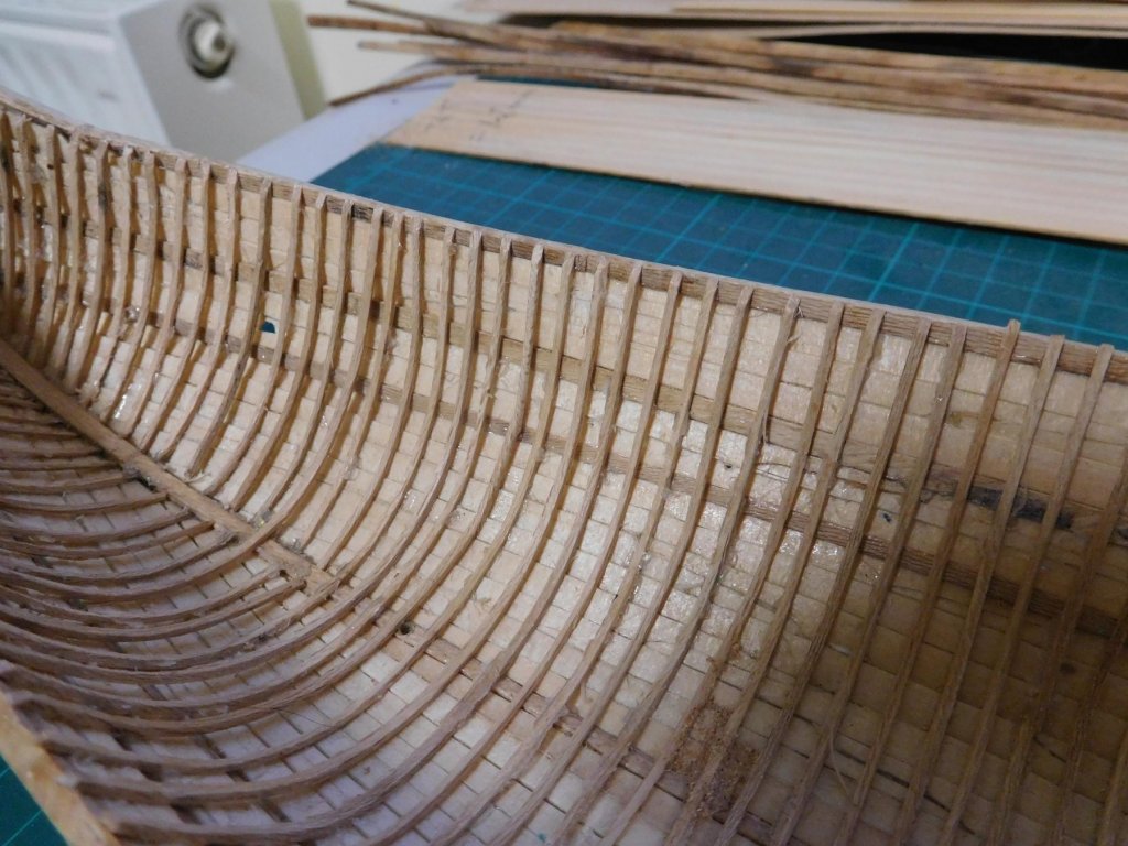
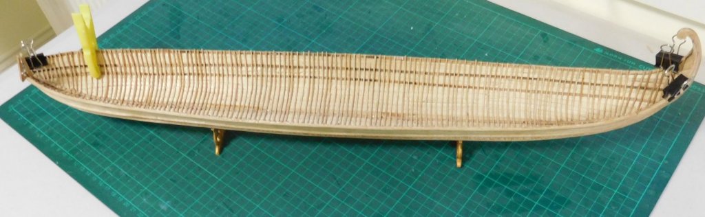
Five frames to go - well, half-frames really, as they're at the extreme ends of the ship. The new frames have made the hull much firmer and stiffer. It really feels like she has some strength to her. I still have to add the keelson and a couple of stringers, which should add further to the hull's integrity. And she looks a lot better with all the frames in place. I used the "one-shot" clamps to keep the hull ship-shape (sorry!) while I glued in all the extra frames. But now the glue has dried, the hull has retained the shape the clamps pulled it into. So I won't have to rely on the deck beams to pull the sides in. I'd hoped this might happen, but I wasn't relying on it. Next step, add the last few frames, then some tidying up - sanding the hull, repairing a few frames that broke off while I was working on the hull (VERY easy to do!), cleaning up glue residue, and trimming the tops of the frames flush with the top of the gunwales. Then I'll be able to go on and cut out the oarports. And now I'm looking ahead to where exactly the deck will go, where to put the platforms for the steersmen etc etc . . . So much still to do. This hobby is certainly teaching me the value of patience . . . Steven

-
Hi Jack, It's the rope loop that holds the yard to the mast. Yes, a higher resolution would be good. The picture isn't very clear. Steven
-
Jack, is there any chance you could post a close-up of the fixing for the yard? It's a bit hard to read the detail at this size. Thanks again Steven
-
Solder and brass blackening
Louie da fly replied to Cabbie's topic in Metal Work, Soldering and Metal Fittings
Further to my post above, the tutorials which show the use of ammonia for blackening also stress the need for safety precautions, including eye protection and ventilation. Ammonia can be rather nasty stuff (it also bleaches and rots your clothes if you're not careful). Steven -
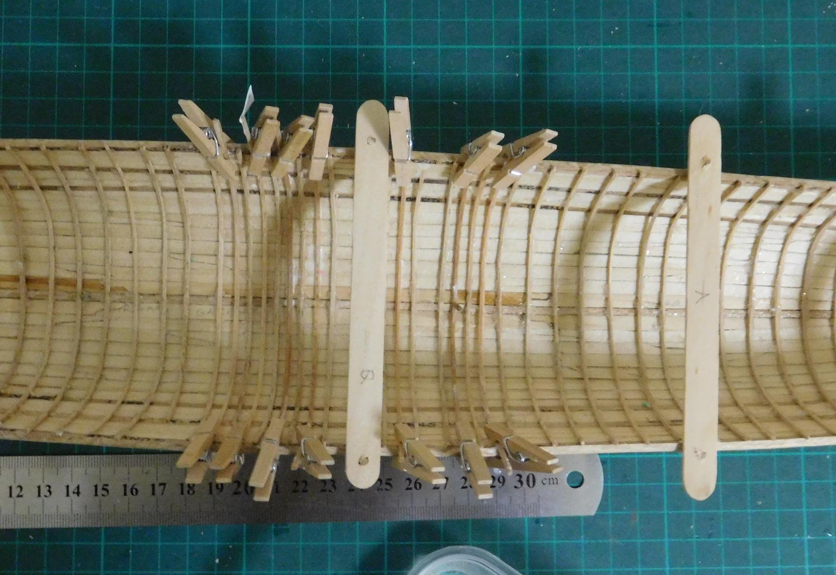
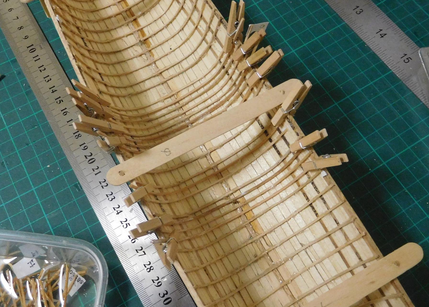
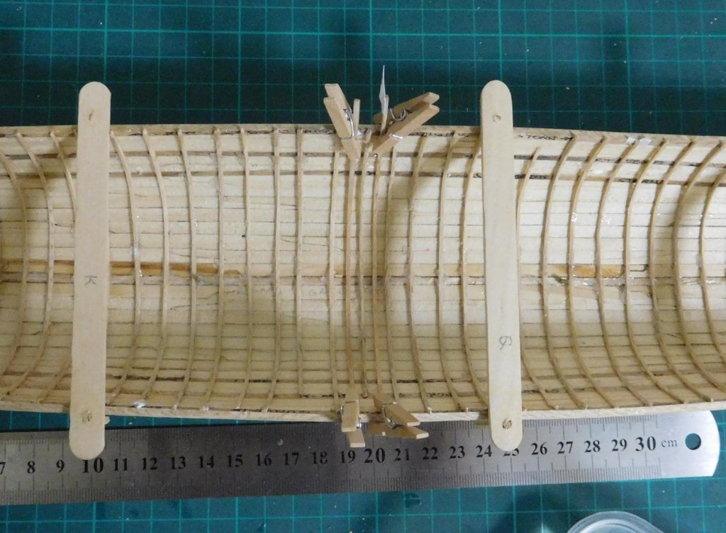
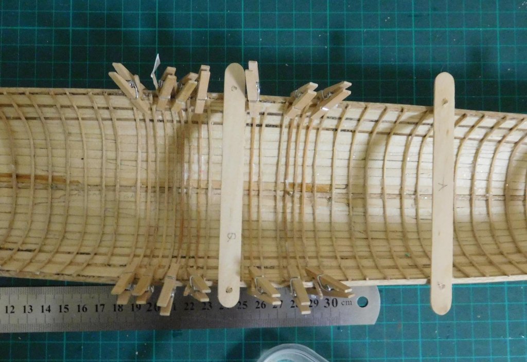
Thanks everyone for the likes and comments. They're greatly appreciated. I got some time free to work on the ship after the family get-together. Making good progress. Here are a couple of photos with all the pegs in use at once. Once the glue is dry I'll be free to re-use the pegs to clamp the rest of the intermediate frames in place. However, it looks like I'll have to make more of them - I've had a larger breakage rate than I'd expected when bending them into position. Hi Druxey, One of the problems with wooden pegs is that they get glued to the frames if you're not careful. Plastic coated bulldog clips sound worth getting - could you post a photo so I can know what to look for? Does your wife remember where she got them (what town/shop)? If I can get hold of them, would you like me to buy some for you as well? Steven


-
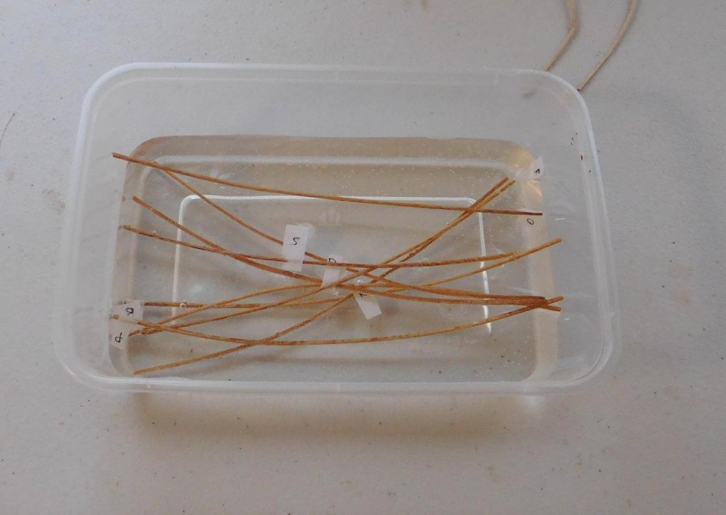
Thanks for the likes, everyone. Much appreciated. Well, I was right; the in-between frames straightened out when I put them in water. So all that work at the beginning of the build went to waste. I'll know better next time (if I'm ever misguided enough to try this kind of build again!). But it made them flexible enough to bend to shape and clamp in place with the tiny clothes-pegs I once bought from an art/craft shop on the off-chance I'd use them one day. So here are the first two in place. And another few. I had to leave some spaces blank for the time being. The one-time clamp got in the way for two of them, and another broke when I bent it (so I have to soak another one to go in its place - but I have several extras I set aside in case this happened.) Tomorrow's Father's Day - the kids will be over, so I may not get any shipbuilding done - but I've got a whole lot of frames in soak for when I next get the time. In the meantime I'm listening to Paul McCartney's Ram album which my lovely wife gave me as an early Father's Day prezzie. Steven

-
Jack, Thanks very much for the prompt reply. I'll study the instructions carefully. Steven
- 174 replies
-
- 1
-
-
- gaeta falcata
- marisstella
- (and 1 more)