HOLIDAY DONATION DRIVE - SUPPORT MSW - DO YOUR PART TO KEEP THIS GREAT FORUM GOING! (Only 72 donations so far out of 49,000 members - Can we at least get 100? C'mon guys!)
×


Louie da fly
-
Posts
7,989 -
Joined
-
Last visited
Content Type
Profiles
Forums
Gallery
Events
Everything posted by Louie da fly
-
 Patrick, that's exactly what I needed! Thanks so much! The netting is for the Great Harry, but I hadn't thought of checking out the Mary Rose, which was almost a sister ship (though smaller). Vossiewulf, I'm sure that's the way it was. And the 10cm (4") mesh would do that very nicely, I should think. Steven
 -
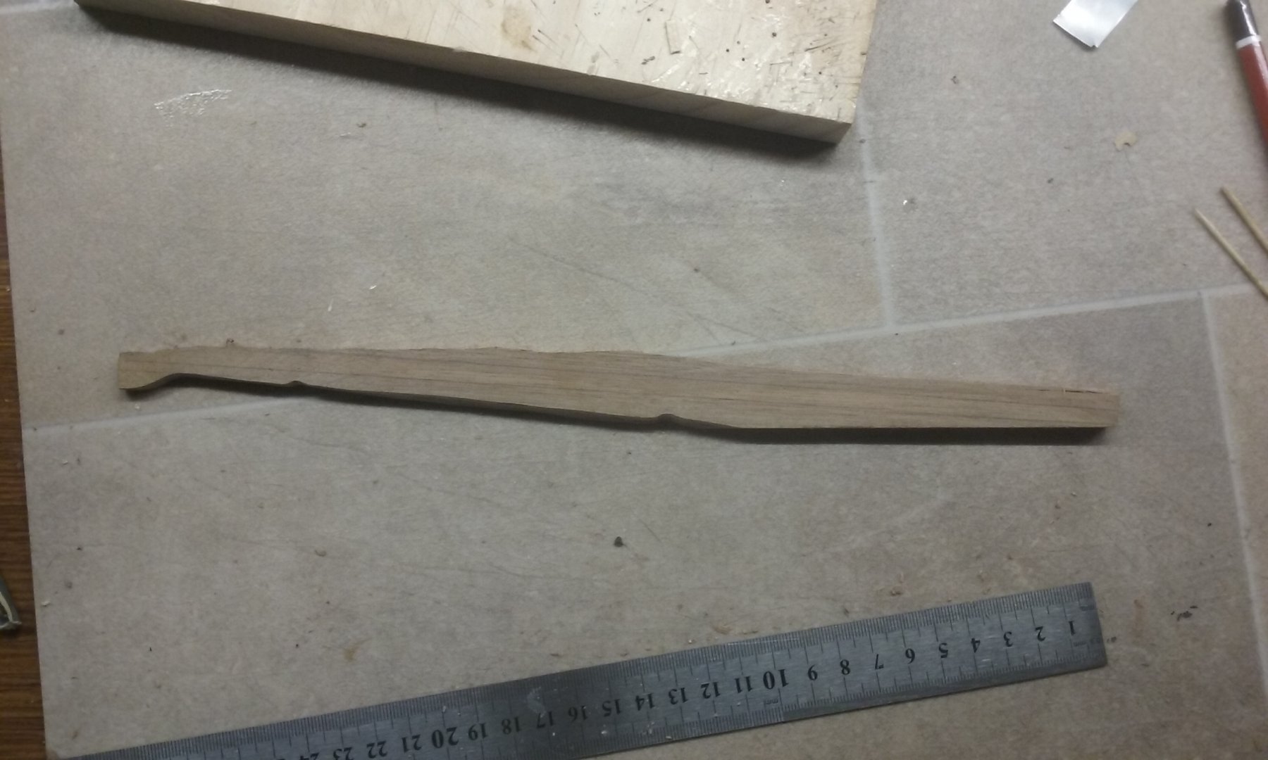
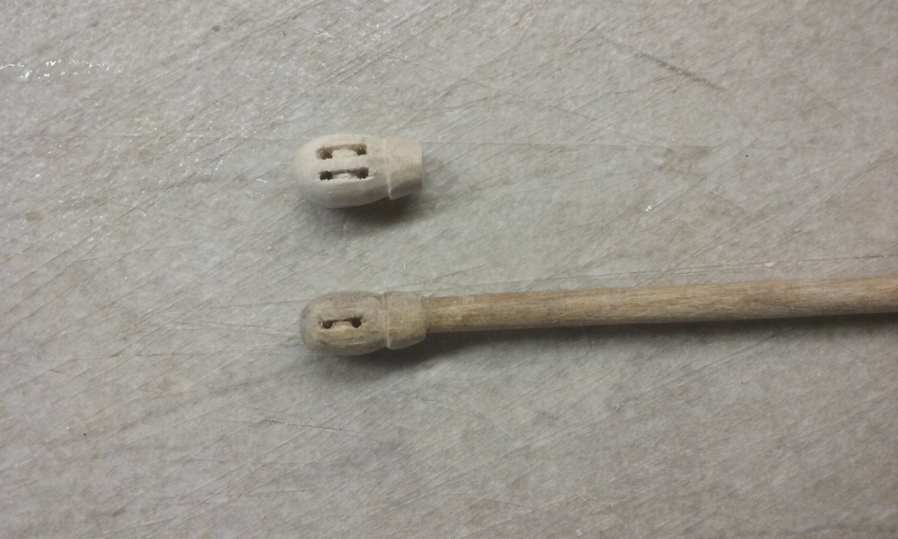
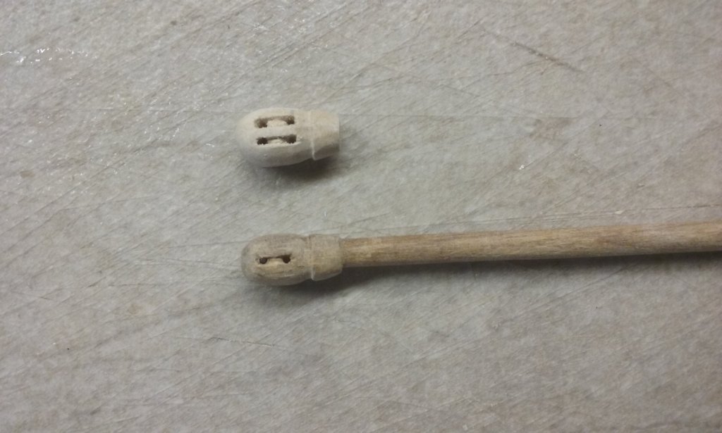
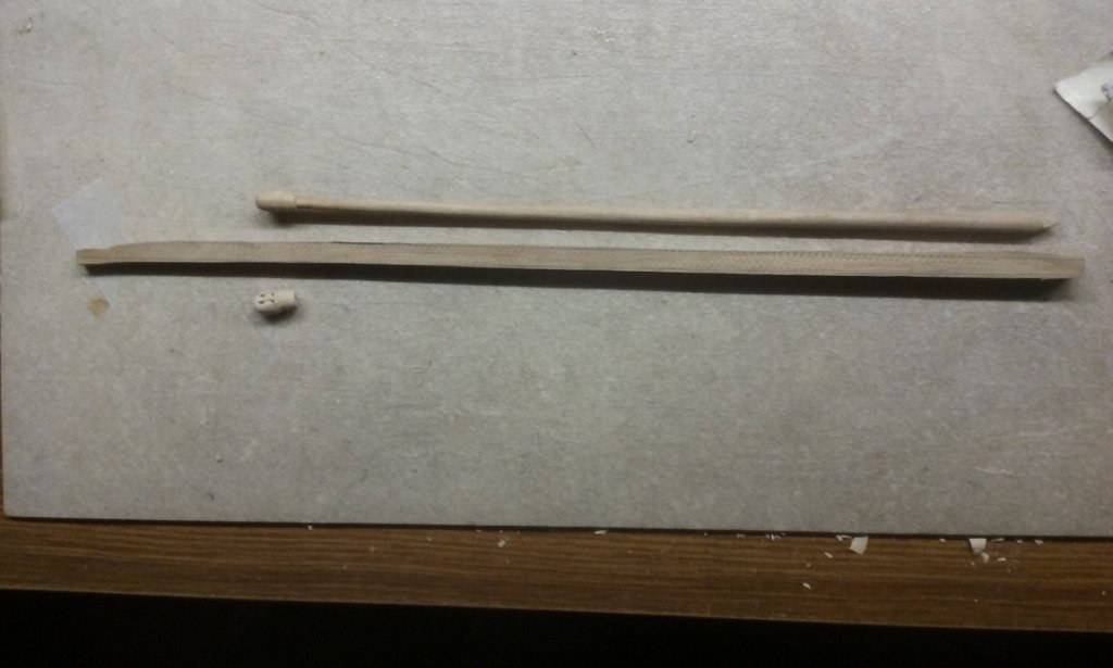
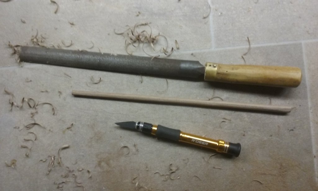
As Woodrat pointed out, unfortunately there's a bend in the foremast. It needs to be corrected and I really don't have much confidence that if I straighten it out by heat bending or whatever it will stay straight. In my view the problem lies in the inherent grain of the wood I made it from. So I've decided to re-make it, this time taking the grain into account. I got another piece of walnut and split it with the grain. Then planed it down roughly square in section, with the line of the mast following the grain of the wood. Then carved it roughly octagonal and using a medium file brought it to a circular section. Now I need to bring it down to the correct diameter - 6mm at the base and 4mm at the top. As I mentioned in a previous post, I've decided to replace the calcets as part of this procedure. Instead of a single sheave they will have two. The existing after mast is straight so it doesn't need replacing, but I'm going to cut off the existing single-sheave calcet and replace it with a double. One is already made and I'm pretty happy with it. Must be all that practice I've had in making them 😁. Steven

-
I'll be following this build with interest, Christos. I think that we'd all like to have a second go at models we've made, if only to correct the mistakes we made the first time - and to improve the accuracy in line with what we've learnt since building the first one. This is a very attractive ship to be modelling, and I think it will be well worth while. It will be interesting to follow the new insights you've developed since your first build. Steven
-
That is really fascinating, Alberto. I'm familiar with both these pictures but hadn't previously noticed the configuration of the oars in either of them. Admittedly, I've only ever seen low-res copies of the Aretino one. If Prof Pryor's calculations are correct (and I'm certainly acting on the basis that they are), the oars are almost exactly as long as the midship breadth of the ship. But pulling them inboard and storing them crosswise would make it completely impossible to move around on the upper deck. Just not an option at all. Your discovery could be the answer to the dromon's oars, rather than having a separate inboard rack for them facing fore and aft between the oarsmen and the gunwale as I'd planned to do. Age of the Galley doesn't mention this problem, and neither does Age of the Dromon (which, given the thoroughness of the book, means the original sources don't either.) It's certainly a possible solution, and as the only near-contemporary evidence (only 300 years wrong😉!) I'd be more willing to follow that than try a different solution for which there's no evidence at all. While I was researching the dromon build I got heavily into the mechanics of rowing galleys (naturally enough) and found the characteristics of a scaloccio and alla sensile rowing absolutely fascinating. And in fact it appears that the invention of alla sensile oar arrangement was what spelled the end of the dromon's mastery of the Mediterranean. It meant a galley with the same number of oarsmen (and thus motive power) could be much lighter because there was no need for a second, upper deck. It would make for a considerably faster, and probably more manoeuvrable vessel, with which a two-banked dromon just couldn't compete, and they seem to have vanished from the scene within a century of the appearance of the new rowing method. I've been following the Black Sea discoveries with great interest. I'm avidly awaiting the archaeological reports, but it's likely to be some years before they'll be published. In the meantime, I have to be satisfied with the videos. One of them shows very clearly the through-beam on which the rudders are supported but unfortunately there's not enough detail - at least for me - to be sure how it all works . Thanks for this insight, Alberto. Very illuminating. Steven
-
I just looked up the constituents of Elmer's wood glue (we don't have it by that name in Oz ) and you can find them at https://www.ehow.com/info_8205845_elmers-wood-glue.html . So it appears that it is either entirely or mostly PVA, depending on the variety. I'd say isopropyl alcohol should work on it, but you'd need to try it out on a sample piece first. Make sure you use enough to dissolve the glue - just a wipe with the alcohol won't be enough. But the good thing is the isopropanol evaporates fast. It also doesn't smell bad (rather sweet, really). Regarding which glue to use, each modeller seems to swear by his /her own favourite. Some use CA (superglue), others epoxy. I tend to use PVA mostly, but it's definitely a matter of personal choice. Each has its advantages and disadvantages. There have been several discussions on the forum about relative merits. Epoxy and CA give off nasty fumes, and CA sticks your fingers together, and apparently starts to crystallize after about 10 years and lose its integrity. That's from reports by other modellers, but others swear by it. The main disadvantages of PVA are that it takes a while to dry, it's vulnerable to water (ok under most circumstances as you're not going to leave your model out in the rain) and I've found in my case the joints can be flexible, which can be a problem if you've put together a complex assembly of fine parts which then go out of true the moment you breathe on them. I've had this happen several times, but I think the main problem there is not the glue, it's the fact that I've used butt joints instead of something that ties the piece together, so the glue is just there to keep it all together instead of doing the major work of joining. I doubt that this would be a problem in your Skuldelev model. They've thought it all out in advance - I've been designing as I go. So if you're doing well with Elmer's, all well and good. I'd agree with Vulcanbomber that you shouldn't use the planking to try to straighten the keel. Try isopropanol on the glue and either straighten or replace the keel. And good luck with it! Steven
-
I'm not sure if this is the right place to ask - maybe it should be in "rigging". However, wherever it belongs, does anyone know the size of mesh (and rope thickness) used in boarding nettings? This is intended for a 16th century ship, but data from any period would be helpful - I think the mesh size wouldn't be likely to change much over the centuries, as the problem to be solved didn't change much. Any information or advice gratefully received. Thanks, Steven
-
Not to worry, Alberto. There are very few things that can't be mended with a bit of work, and even the best of us have sometimes forged ahead where angels fear to tread and had to go back and start again. Stick with it; you'll get there. Regarding the bent keel, there are various posts on the forum on how to fix such things (though of course unfortunately I can't remember where I saw them). If worst comes to worst, it might be necessary to make a new one. Is the keel made of ply? If so, it's not an inherent twisted grain problem as I faced when I started my dromon. If you used PVA (white) glue on the frames you can dissolve it by soaking in isopropyl alcohol (isopropanol). Both that and methylated spirits (ethanol with 5% methanol otherwise known as wood alcohol) are commonly called rubbing alcohol, but isopropanol is the only one that works on PVA, as I discovered to my cost. One thing is that you've learned an important modeller's lesson. Don't glue unless you know you've got it right. You'll find a lot of modellers "dry fit" things together before they add glue. It can prevent a lot of heartache. And don't give up because something occasionally goes wrong. With patience and perseverance you'll get there, even if you have to retrace your steps once in awhile. Speaking for myself, and I'm sure for everybody else on the forum, there's no build that ever goes perfectly. And as your level of skill improves and your own standards for your work raise, you'll find ever new and more interesting mistakes to make! Having said all that, I'd like to add that you've chosen a beautiful ship to build. I'm sure it'll turn out to be something you'll be very happy to have done. Steven
-
Thanks for this Alberto. This is very valuable info for anyone interested in mediaeval Mediterranean vessels. Steven
- 263 replies
-
- 2
-

-
- nave tonda
- round ship
- (and 2 more)
-
Thanks, Dick, Mark and Mark. I suppose I'll just have to do what seems right. But I think something will need to be done at deck level, because these masts and sails would have imposed pretty strong forces on the vessel. Carl, I remember removing the wedges being mentioned in Hornblower in the West Indies when Hornblower is an Admiral and his flag captain decides to remove the wedges to speed the ship up in chase of a faster vessel.Hornblower thinks it's unwise, but convention forbids him as Admiral to give a captain advice in the handling of his own ship. Jack Aubrey might have done it, but I think he relied more on cross catharpins. I have no knowledge of it being done in the real world. Steven
-
Ah well, that's ok. I have a solidus from the reign of Michael VII. I'll just have to copy that, won't I? Steven
-
Hi Mark, I thought of the heat gun method (I do have one), but wood tends to return to its natural shape after a while - at least it has with me . . . Steven
-
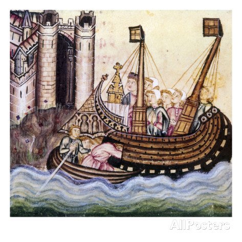
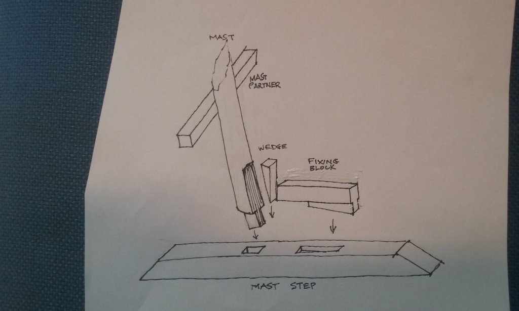
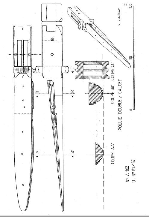
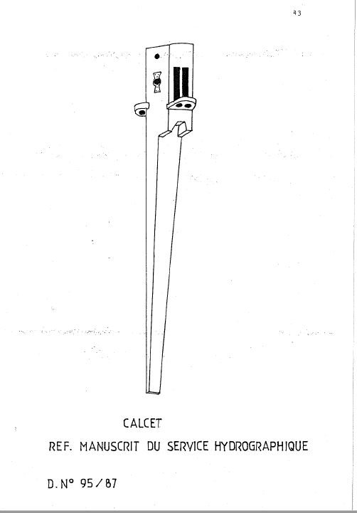
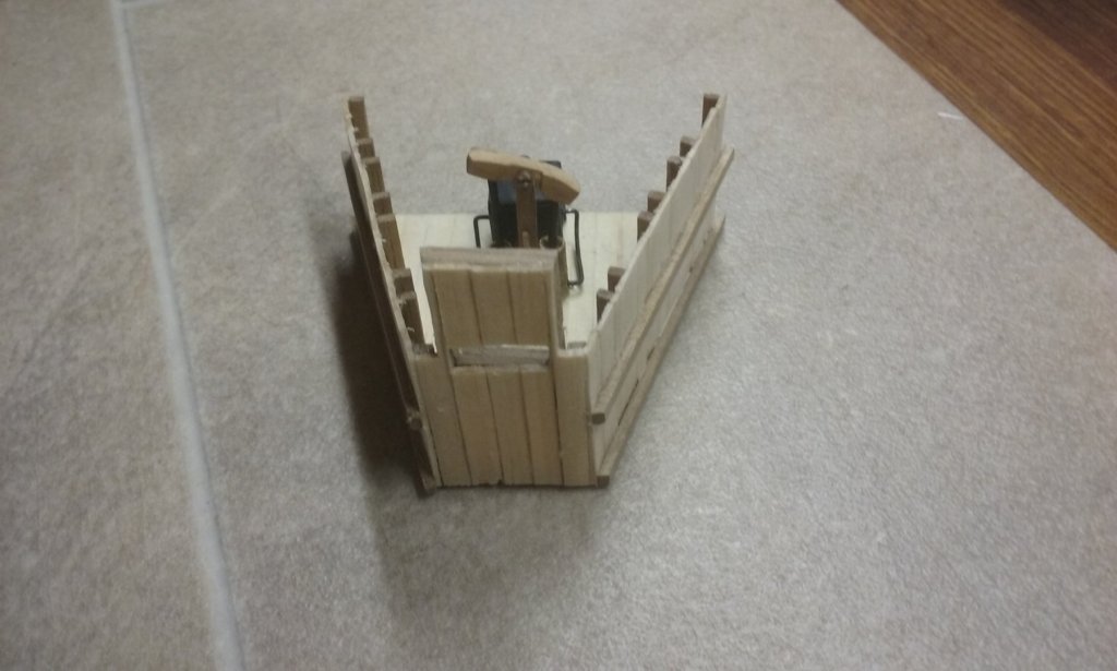
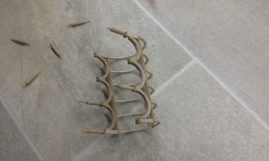
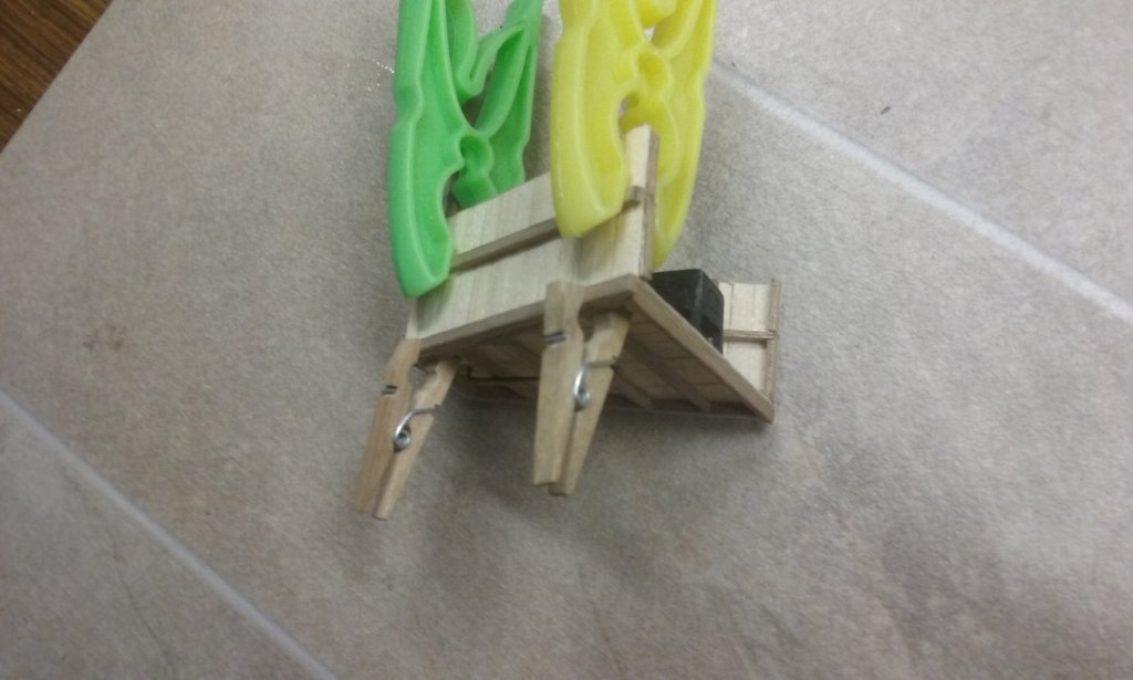
Pat, that's a good idea. I'll have to try it (on another model - unless I can retrieve the situation - I might just put pins in the forward two columns and let the rest just sit on the deck.) Thing is, I'm not all that confident of my accuracy with a drill. Always seems to wander, even though I put in a "dimple" to start the hole off. Dick, I'm afraid you're right. Curses! Looks like I'll have to make another mast (sigh). OTOH I've recently come across a calcet in an archaeological find (the only one I know of) and it has two sheaves, rather than the one I've put in each of my own calcets. As that's from a carrack the dating's well different, but the yards and sails of a dromon would have been pretty hefty, so maybe I need to replace the calcets anyway. So making a new mast isn't all that much extra work . . .😐 Here is the calcet - it's from a Genoese nave built in 1503, and must relate only to the lateen mizzen. The two illustrations seem to be of different calcets. The first is from the wreck; the second I believe to come from a contemporary manuscript - the text doesn't make it very clear. Glad you like the poop superstructure. Rather fiddly, but I seem to be taking more care with this kind of thing as my experience grows. Slows me down, but worth it in the long run, I think. Still learning lessons, though. Using butt joints to put together the two halves of the arches that go over the top meant that when you pick the structure up to work on it the arches squeeze inward and you have to pull them out again. PVA glue is fairly flexible, so it's somewhat forgiving in this regard, but perhaps if I'd used a more "rigid" glue the problem wouldn't have arisen anyway. I'd pretty much decided to use wedges. The earliest ships I know that show the fixing of the masts are in the 12th century Spanish Cantigas de Santa Maria and have what I thought were huge wedges, but I now believe to be posts coming up from below decks, to which the mast is lashed. Some seem to be merely fore and aft of the mast, others are all around it as in the picture below. As I've seen a reconstruction of one of the Yenikapi ships with a vertical post below decks with the mast lashed to it and to the (horizontal) mast partner, perhaps that's the way to go, especially as mediaeval galleys customarily fought with their masts lowered so they must have had a means to do it fairly quickly and easily - though I suppose wedges are probably just as good for that. Or perhaps just wedged in place at the mast step and lashed to the mast partner? The mast step is of the form found in the Yenikapi wrecks, so perhaps this is the way to go. (The wedge and fixing block are my own idea of how it may have worked). Oh and I suppose I'll have to mint a coin to scale to put at the base of the mast . . . Steven
-
Hmm, it's a thought. I'll have to look how closely it approximates to the scale I need. Steven
-
Beautiful work Alan. Very painstaking and precise. I'm in awe of people like you who can achieve this kind of precision. I'm a bit too "she'll be right" to achieve that - at least at my current stage of modelmaking. Steven
-
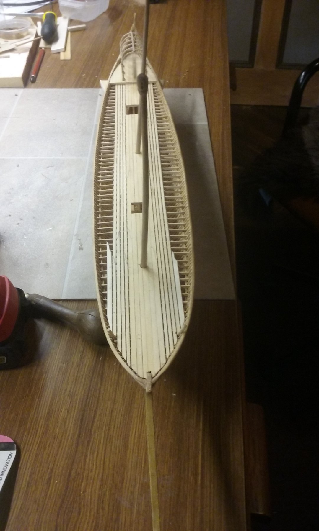
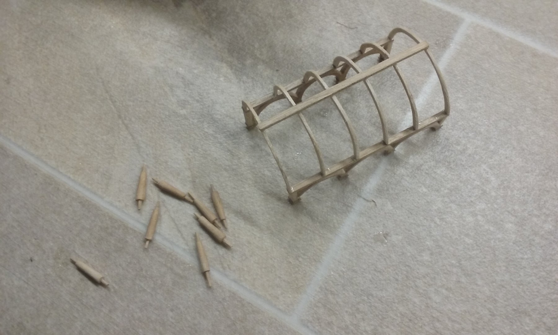
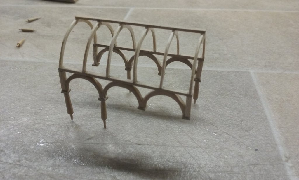
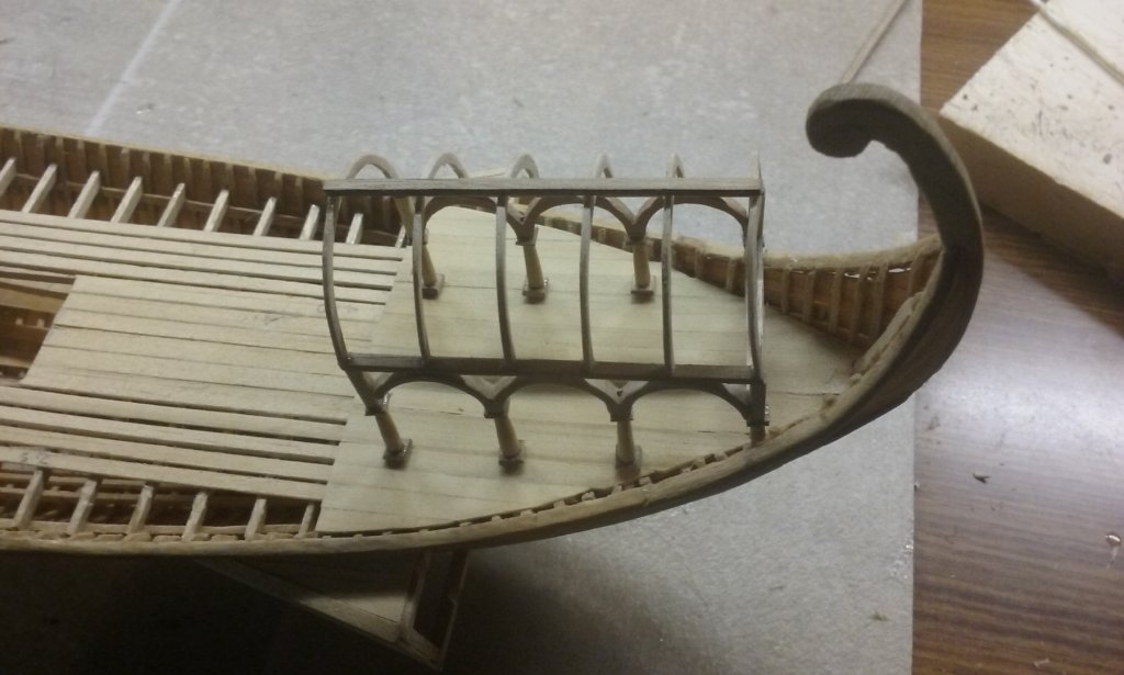
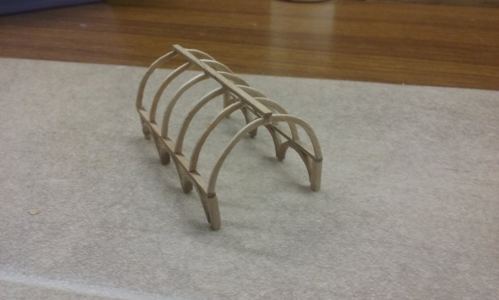
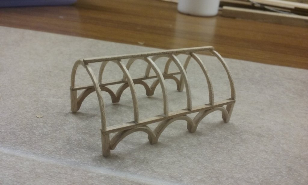
Thanks for all the likes, everybody. They're much appreciated. Pat, you ain't seen nuthin' yet! Here it is almost complete and (dry fitted) in place on the poop. I had intended to have the tenons at the column bases go through the deck to hold the assembly in place, but then decided I just can't place holes in the deck accurately enough, so I cut them off. I hope that wasn't a mistake . . . (The masts seem out of line because they're currently only dry fitted. I have no idea how the Byzantines kept masts in place - did they use wedges as was done later, or were they lashed to through-beams or fixed posts, or a combination of those, or what? The earliest definite pictures I know of that show wedges date to the late 12th century - maybe 200 years too late. If anybody has any ideas or evidence, I'd appreciate your input.) Steven

-
Thanks, Greg. It might be easier to just get tulle. There's a Spotlight and a Lincraft in Ballarat. Steven
-
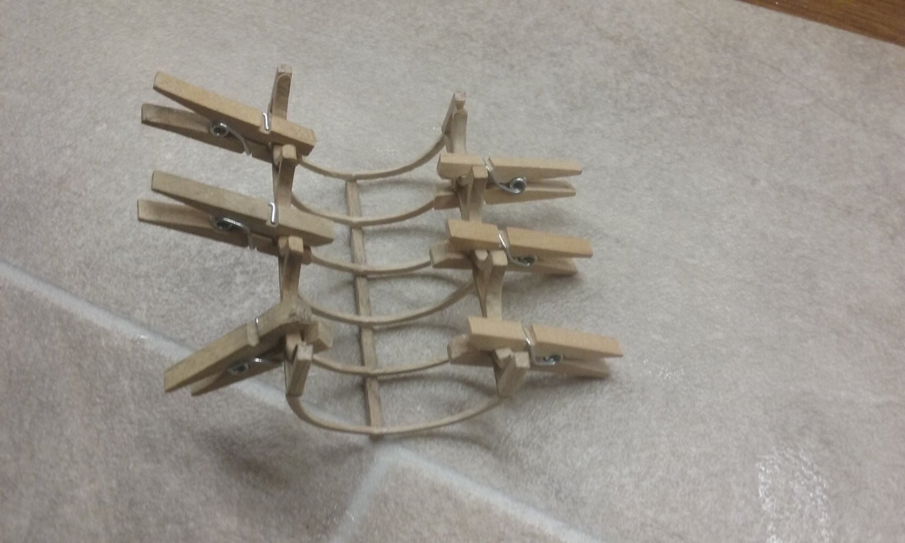
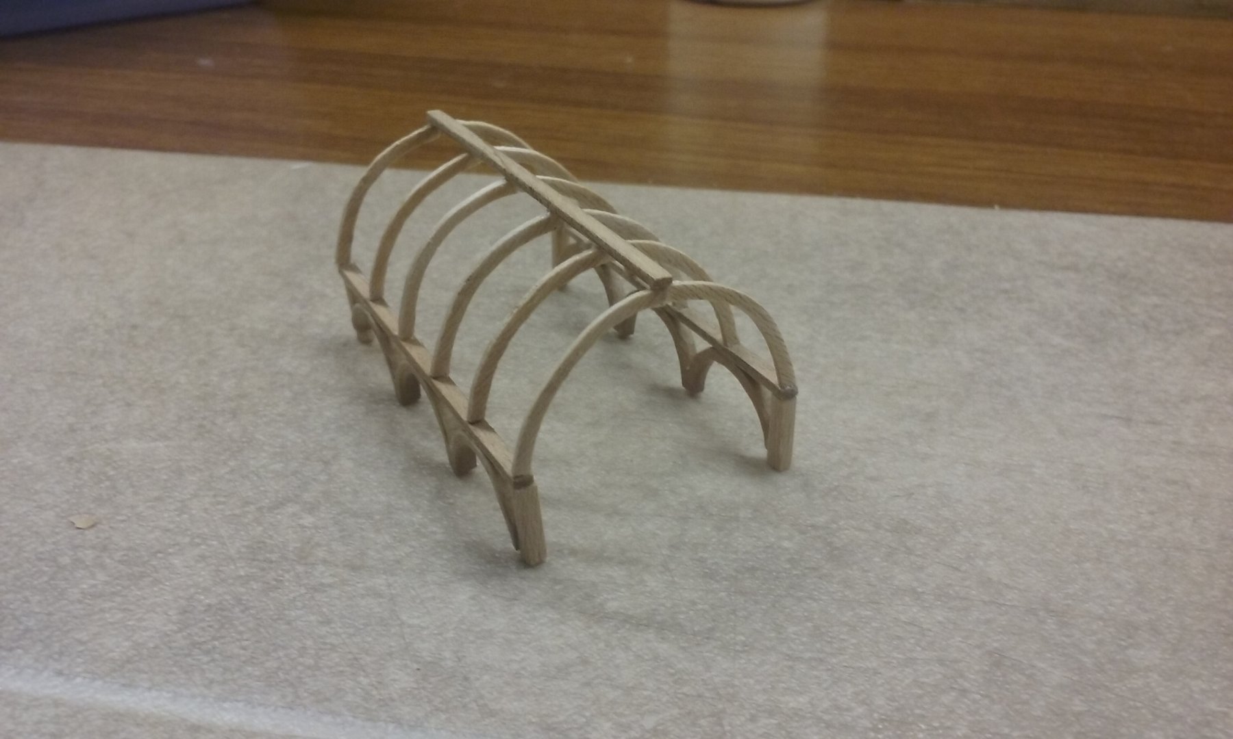
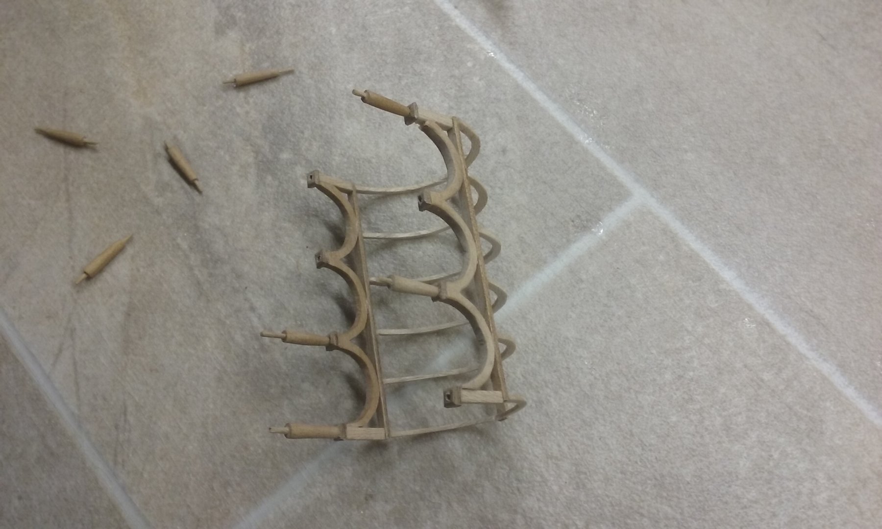
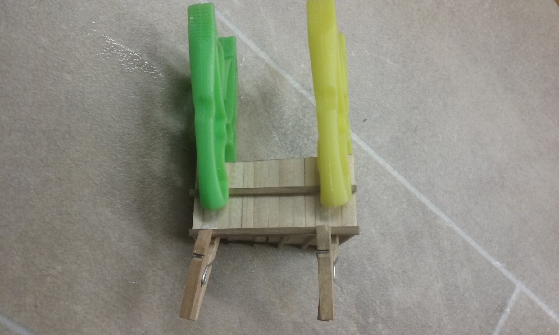
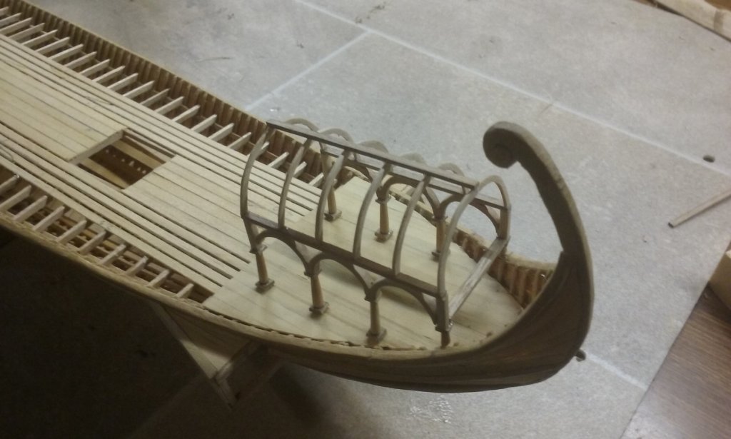
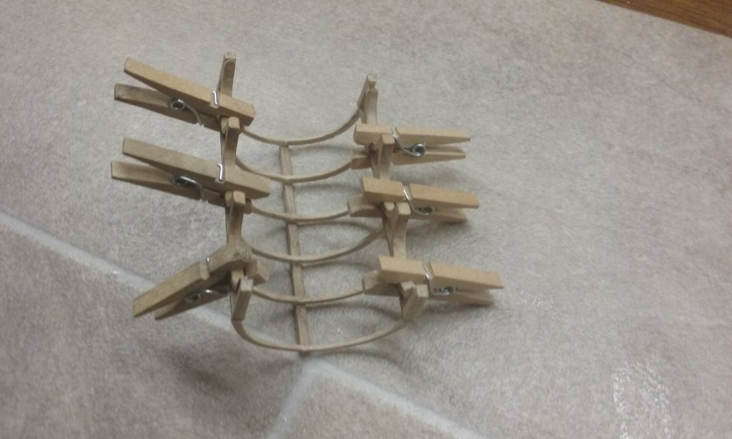
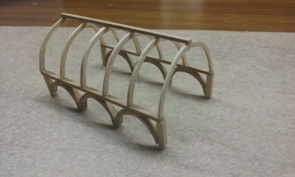
Planks trimmed: Adding the battens (if that's the right name for them): More to do . . . And the awning over the poop deck: Gluing the support arcades to the roof arches: Column capitals glued on the bottoms of the arcade arches and columns made (no lathe, so all carved by hand): Dry fitting the columns. Steven


-
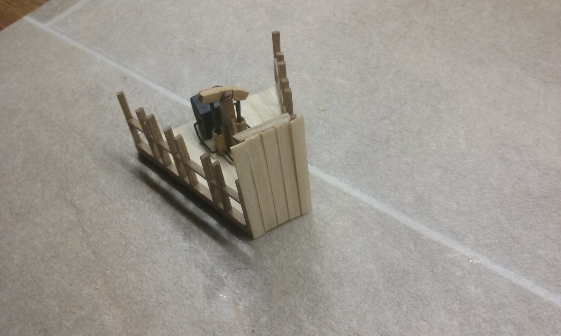
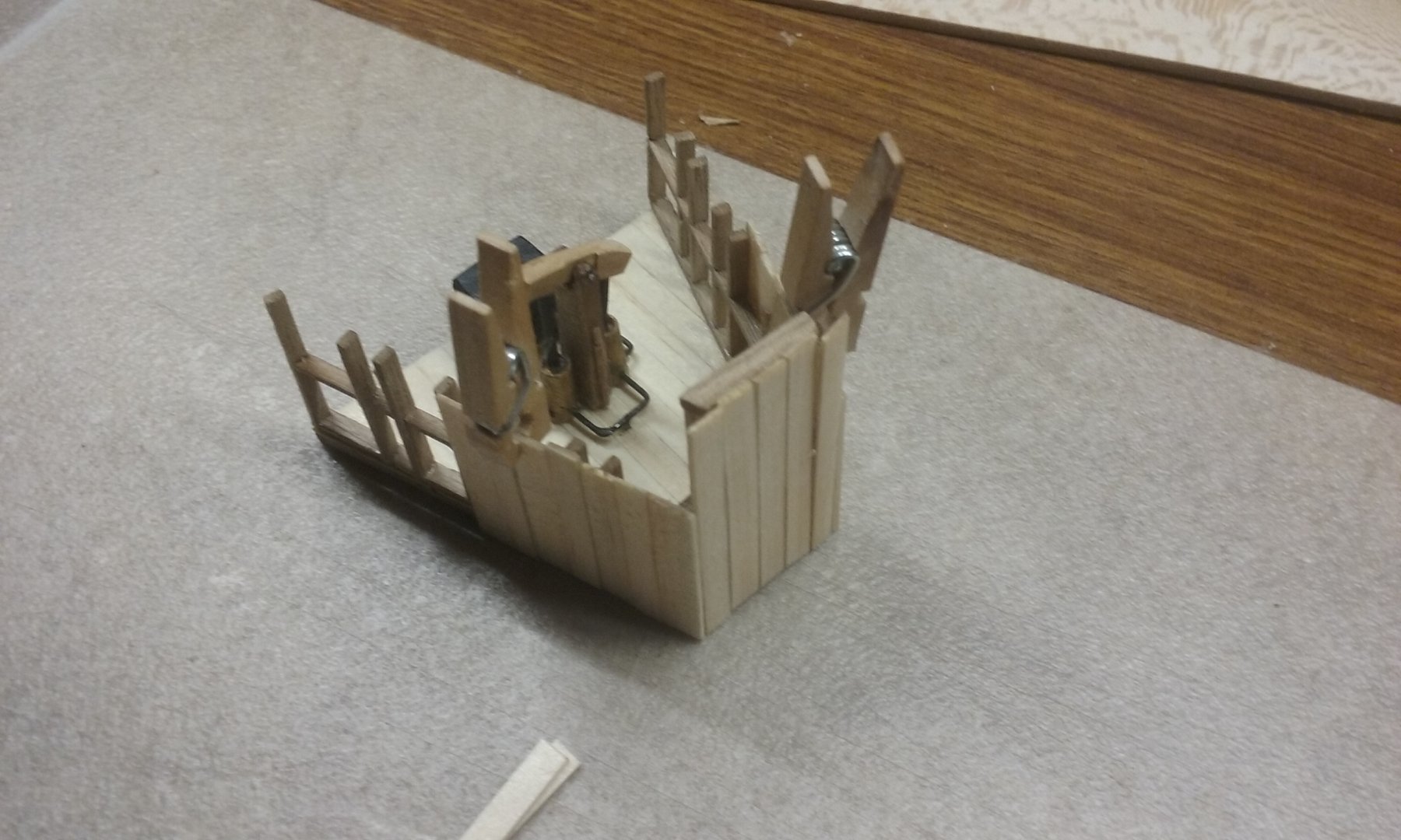
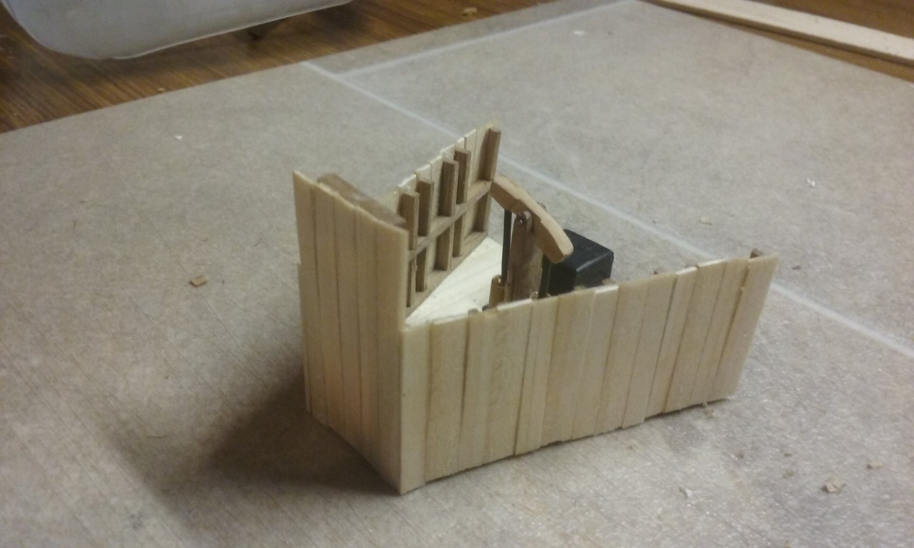
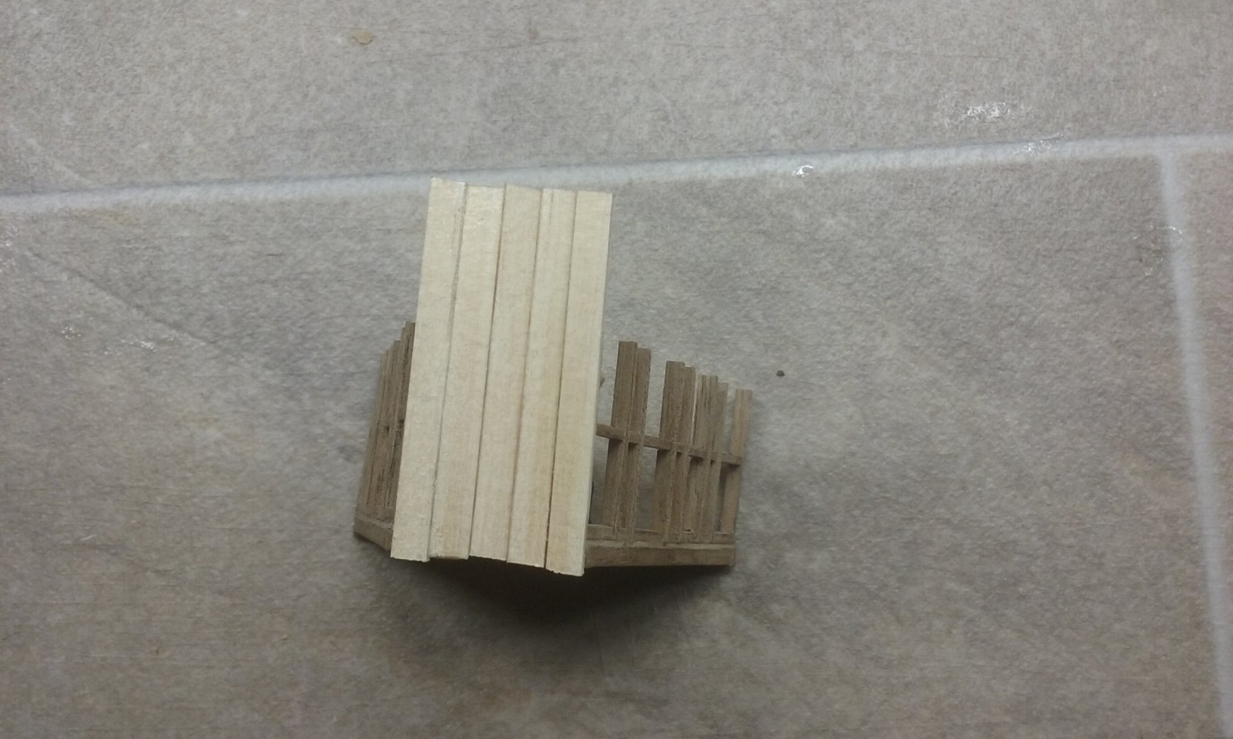
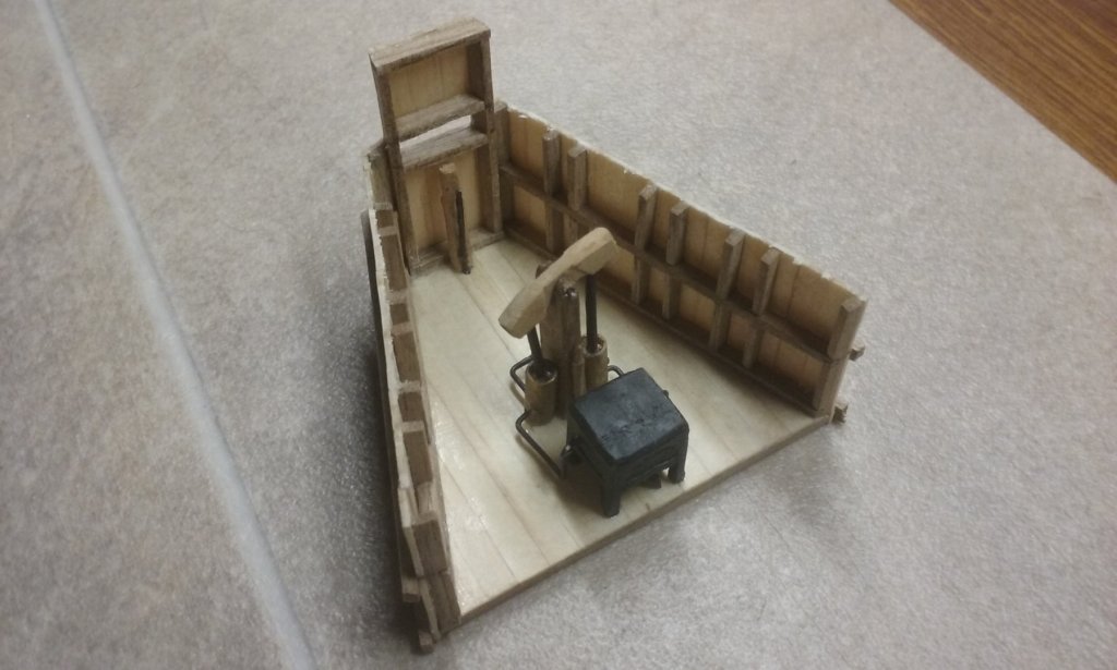
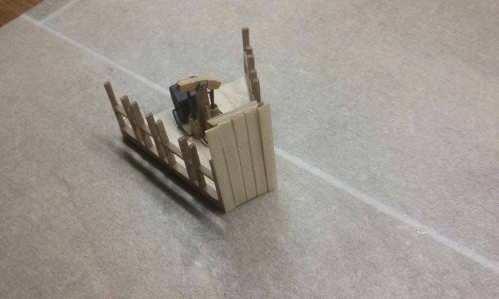
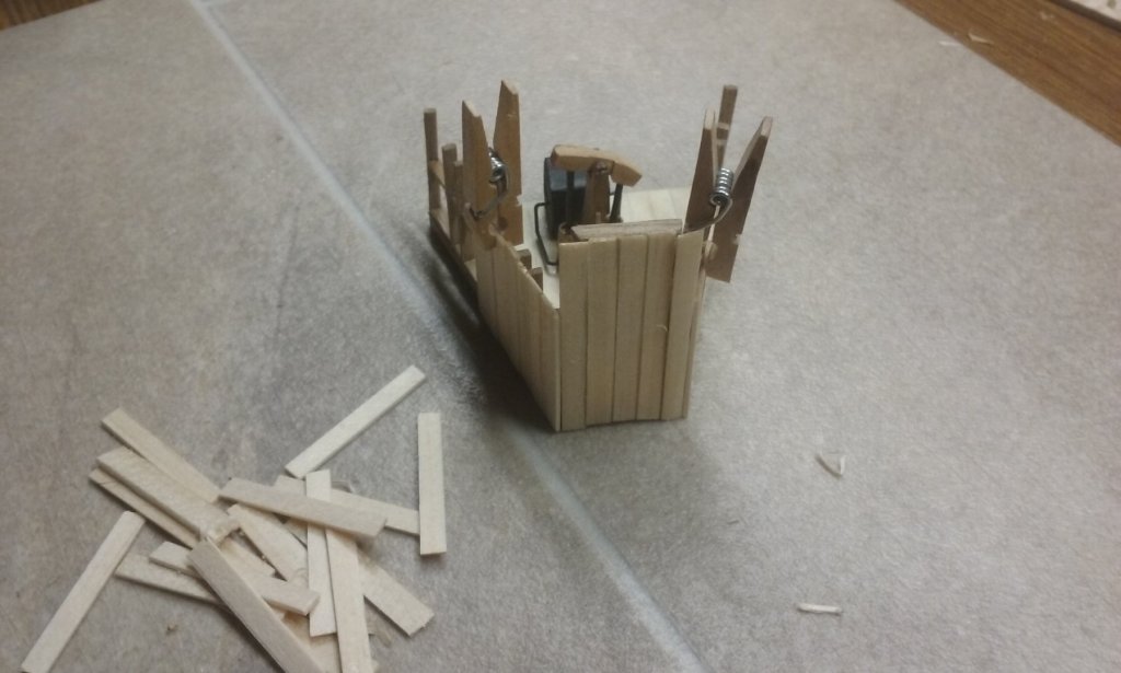
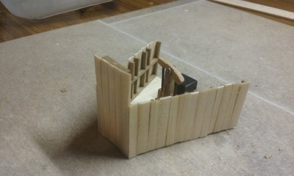
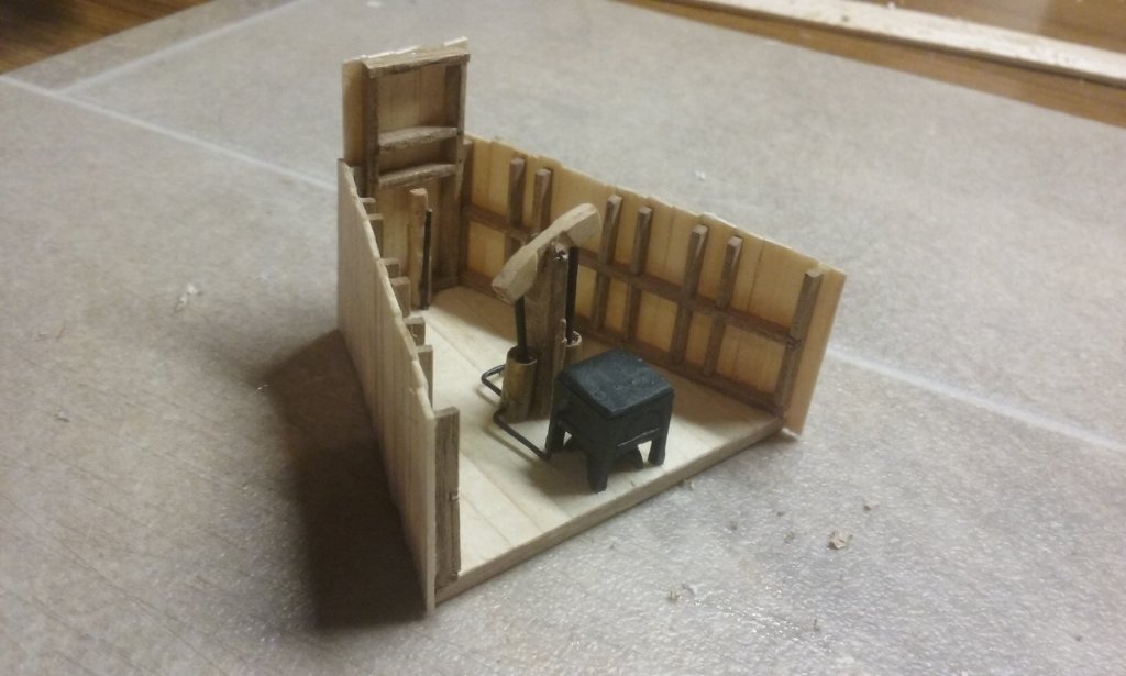
More work on the new forecastle. Parapet planking started: And continuing: And complete: Steven


-
Thanks, Greg. Can you get the nets separately, or do you have to buy a whole lot of stuff that may never be needed (I don't expect I'll ever be making a Seydlitz)? Pat, if I can't get the netting by itself I'll probably follow your advice. Fortunately my wife knows everything about fabric! Steven.
-
This is coming together well, Slowhand. I'm glad you didn't give up on it. Whatever historical accuracy issues there may be with the model as issued, you're putting together a very well worthwhile build. Steven
-
What an interesting subject for a build. And you're doing an excellent job on it. 1:150 is not an easy scale for a ship of this size and type. I look forward to further progress. Steven
- 90 replies
-
- 4
-
-
- bomb ketch
- pyro
- (and 1 more)
-
Unbelievably brilliant, Greg. A magnificent build - the complexity and detail, and of course the weathering. What an amazing result. I have to ask, though. What did you use for the nets? I'm going to need something similarly fine if I want to put boarding nettings on my Great Harry. Steven
-
Lovely crisp work, Patrick. I bet the piece of wood just died of fright when it saw that big spanner. If at first you don't succeed . . . use a bigger hammer. Steven
- 756 replies
-
- 3
-
-
- galleon
- golden hind
- (and 2 more)
-
Not as far as I know, Dick. Not all the results are out, but though one of the Yenikapi galleys had almost the whole of one side still in existence (including two or three oarports) nobody seems to have mentioned any rudders - or even oars, for that matter. But who knows what the Black Sea finds will turn up? Steven
- 263 replies
-
- 2
-
-
- nave tonda
- round ship
- (and 2 more)