HOLIDAY DONATION DRIVE - SUPPORT MSW - DO YOUR PART TO KEEP THIS GREAT FORUM GOING! (Only 72 donations so far out of 49,000 members - Can we at least get 100? C'mon guys!)
×


Louie da fly
-
Posts
7,989 -
Joined
-
Last visited
Content Type
Profiles
Forums
Gallery
Events
Everything posted by Louie da fly
-
 Can't help you with the paint question, but are you also interested in the designs on the shields? The only Viking ship ever found with shields on the sides was the Gokstad ship. Half the shields were painted yellow, the other half of them were painted black, and they alternated - one black shield, one yellow, one black, one yellow . . . There were no designs on the shields apart from the yellow or black colouring, though some fragments of Viking shields have been found with more elaborate decoration. See http://members.ozemail.com.au/~chrisandpeter/shield/shield.html#Decoration The Amati model appears to be based not on the Gokstad ship but the Oseberg ship, which was much more elegantly shaped. But even the Gokstad shields are more likely to have been there for decoration rather than combat. I realise this doesn't answer your question, but I hope it's of some use to you. Steven
 -
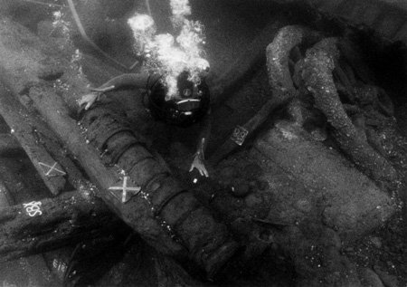
That's amazing, Fabio. The carrack in the picture is flying the flag of the Lomellini family, who owned the Lomellina! (See https://it.wikipedia.org/wiki/Giannotto_Lomellini). What year was the picture painted? Perhaps it is the same ship! The land-based artillery have the same kind of wheels as in the wreck's cargo, and it is thought the barrels of those cannons were recovered after the ship sank. But probably the wheels weren't valuable enough to salvage. I haven't seen this image of a culverin before. It's certainly in very good condition. I'm interested in the book. I'll have to find out about it. I wonder if it is available in English. Best wishes, Steven
- 197 replies
-
- 2
-

-
- santa maria
- carrack
- (and 1 more)
-
This looks good, Patrick. Apart from your own pragmatic reasons for having a single large opening for the forecastle, contemporary pictures of carracks (yes, I know, 50-100 years or so earlier) show them with large openings both under the main deck at the break of the aftercastle, and at the entry to the forecastle. I realise you're doing a galleon not a carrack, but I think you're on the right track with this. And yes - the support beam for the deck beams is the beam shelf. Steven
- 756 replies
-
- 3
-
-
- galleon
- golden hind
- (and 2 more)
-
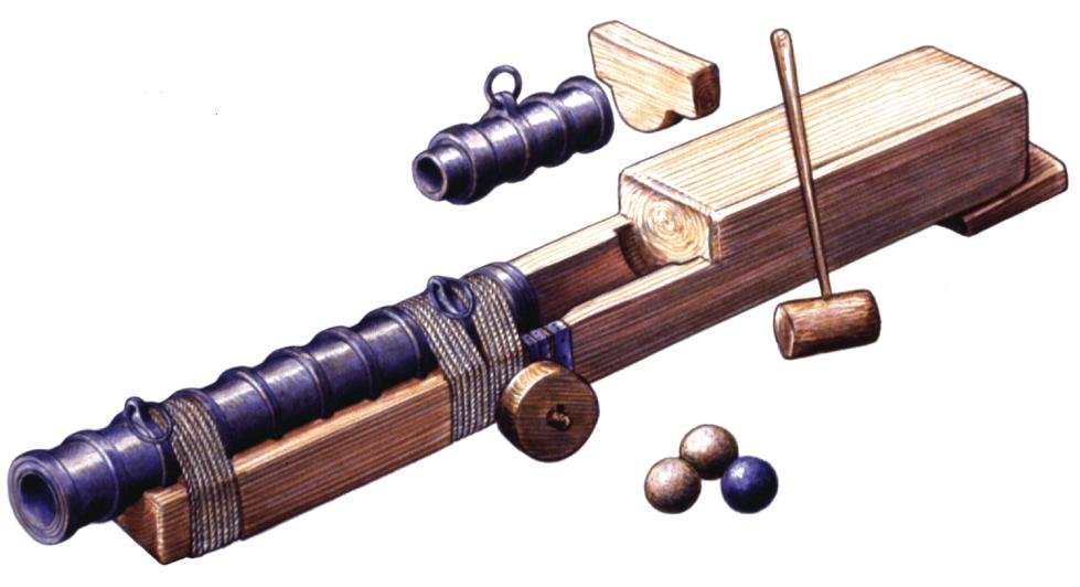
Beautiful work, Luponero (that's Black Wolf in English, isn't it?). I'm glad you're enjoying the dromon build. I'm hoping to do a carrack at some point in the future. The balustrade is very nice - lovely crisp detail. I love your cannons - they're beautifully done; you're very accomplished with the lathe. Your cannons are very much like the ones they found on the wreck of the Genoese ship Lomellina (built 1503, wrecked 1516), with only a few differences as you would expect between one region and another. Note those large wheels don't belong to the ship's cannon - they appear to have been part of an artillery train the ship was carrying as cargo when she sank. Steven
- 197 replies
-
- 3
-
-
- santa maria
- carrack
- (and 1 more)
-
Thanks, Pat. Mark, comment appreciated. Maybe I will. I'm going to remove and re-use the siphon assembly, but it really would go against the grain to just throw the forecastle away. Heaven knows where I'd display it. Steven
-
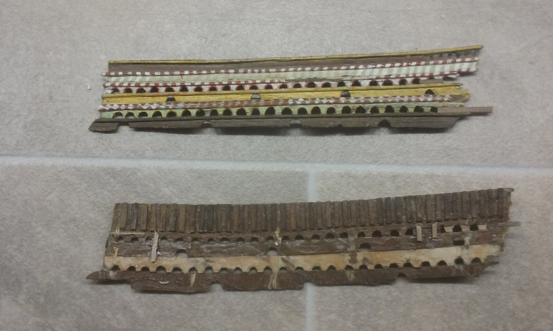
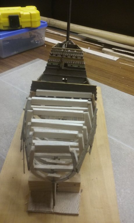
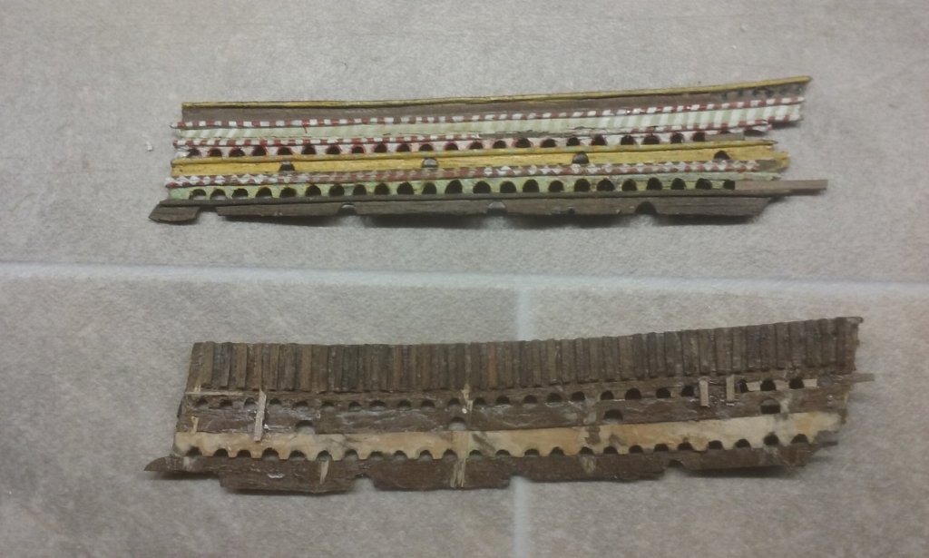
After a rather frustrating session with the dromon build, I thought I'd take a bit of a break and work on the Great Harry as a relief. Just fixing up the broken arched gunports bit by bit. I've had to reinforce them at the back in places because they're so fragile. I sometimes impress myself, though - when I was 17 I'd thought of reinforcing these runs of arches with paper glued to the back of the wood. I think that's pretty cool for a 17 year old. Still broken in places so I've got more to do, particularly at the after end of these panels. I thought of also fixing up some of the arches that I made the wrong size way back when, but I think this would go against the original idea of restoring it to the way it would have been if I'd repaired it properly at the time. (One exception - I've given the hull a "rounder" shape than I'd originally done, on the basis that if the Mary Rose had been found at the time I would have done it that way). And I've glued in over-size balsa deck beams which will be trimmed down to make a smooth line for the upper deck (Balsa's really great for this kind of work). All a bit rough and ready and not square at the moment. That will come with the trimming, and the roughness will be hidden inside the hull - as it was when I first built her. Not sure if I'm going to camber these beams - I didn't know about that at the time and probably wouldn't have bothered if I had. Steven
- 740 replies
-
- 4
-
-
- Tudor
- restoration
- (and 4 more)
-
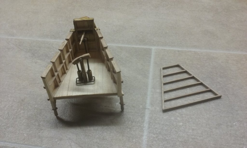
Thanks for the likes. John, thanks - very much appreciated. Don, welcome back! (and thanks for all the likes!). I really enjoyed following your liburnian build and I'm grateful for the comment on my own build. After a certain amount of frustration in realising the forecastle wasn't going to work and couldn't be fixed but needed to be replaced by a new one 😭, I've made a start on the replacement. It's rather smaller than the previous version to make it fit better at the bow, while still having enough space for the siphon plus crew. In some ways it's a relief - in making a new forecastle I get to re-do some things I wasn't completely happy with in the first one. Because of the maindeck sheer and horizontal foredeck, the're'll be a larger gap below the after end of the foredeck than forward. This will be convenient for storing the anchors, which I hadn't previously been able to work a place for. Steven
-
Thanks everybody for the likes. Michael, sorry for not replying earlier. Your comments are much appreciated. Patrick, I agree with your assessment. Several of the pics in my earlier post were also from Landstro"m's The Ship. Since that was written a lot more evidence has become available, which is why my model is somewhat different from his reconstruction. However, I agree about the forecastle, particularly that the deck should be horizontal and the forecastle itself should be lower. Unfortunately, it looks like I will have to completely rebuild it rather than just remove the arches.😖 Oh, well. Back to the drawing board . . . Steven
-
Hi Pat, That's my thought as well. The arches should come off fairly easily and I can see how it goes from there. I still think the two mast option is the better one. Steven
-
Carl, I realised I'd misread your post, thinking you simply meant seawater, not oil for the siphon. You're quite right - I'll have to ensure the deck is horizontal, otherwise spilt oil could flow back into the ship. (it might anyway if the ship is bouncing around on the water, but that's a different problem. I can at least reduce the risk as much as possible.) Thanks for pointing this out. Steven
-
Oh, I've just "plonked" the forecastle on top of the deck for the moment. When properly in place it should follow the sheer of the deck at the bow, which is fairly shallow. However, I'll check it out in case it looks like causing problems. Steven
-
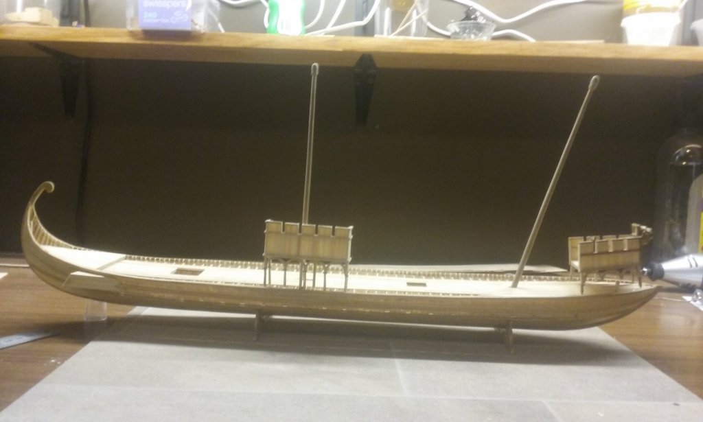
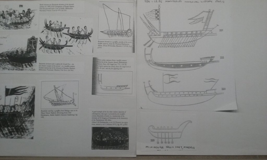
Having all but completed the forecastle, I've been having second thoughts about its height. Looking at the dromon with the forecastle at its present height placed temporarily at the bow, it looks like it will interfere badly with the lateen foresail in the current configuration. As I see it, I have two options - to take out the foremast and make the dromon a single-master (you may remember I'd spent a of time and effort earlier in the build trying to decide whether to go with one or two masts) - or reduce the height of the forecastle. Though going single-masted would require re-doing some of the deck planking and putting in a new mast step, that's not necessarily a reason not to do it. There's plenty of contemporary written evidence that can be read to support the idea that dromons were single masted. On the other hand, there's just as much evidence to the contrary. Looking at a few near-contemporary illustrations of galleys (though none of them are dromons) it appears that the forecastles of galleys of this time (those that had them) were considerably lower than I've made mine. I started with the idea of that a dromon would have a higher forecastle than those of other cultures, because being equipped with a Greek Fire siphon it would need enough height below the forecastle deck for the oil reservoir. However I've checked the available space and it looks like I could just as easily put the reservoir on the forecastle deck without messing anything up. This would reduce the forecastle height and both make it look more like contemporary ones, but more importantly, wouldn't interfere with the foresail. But it would mean I'd have to get rid of all those arches and columns I'd put so much work into (sigh). The lower ends of the lateen yards will still have to be a certain distance above the deck because dromons had structures (presumably two or more upright stands set into the deck) to rest the masts on when not in use, and similar ones for the yards. And the masts and yards would have to be above head height to allow free movement beneath. On contemplation I think this is the right answer - I just haven't summoned up the nerve to change it. I'm going to think about it overnight and if I still feel the same way tomorrow, it'll be "goodbye arches!" Steven
-
Looking really good, John. On the third photo above, the transom looks a little out of square, but I expect that's just a trick of the photograph angle. Steven
-
Beautiful work, Dan. And fascinating following your analysis and reconstruction of the complex details of this section of the superstructure. Captain Hartley isn't based on the Fat Controller, by any chance? Nah, can't be. Wrong hat . . . Steven
- 238 replies
-
- 5
-
-
- leviathan
- troop ship
- (and 2 more)
-
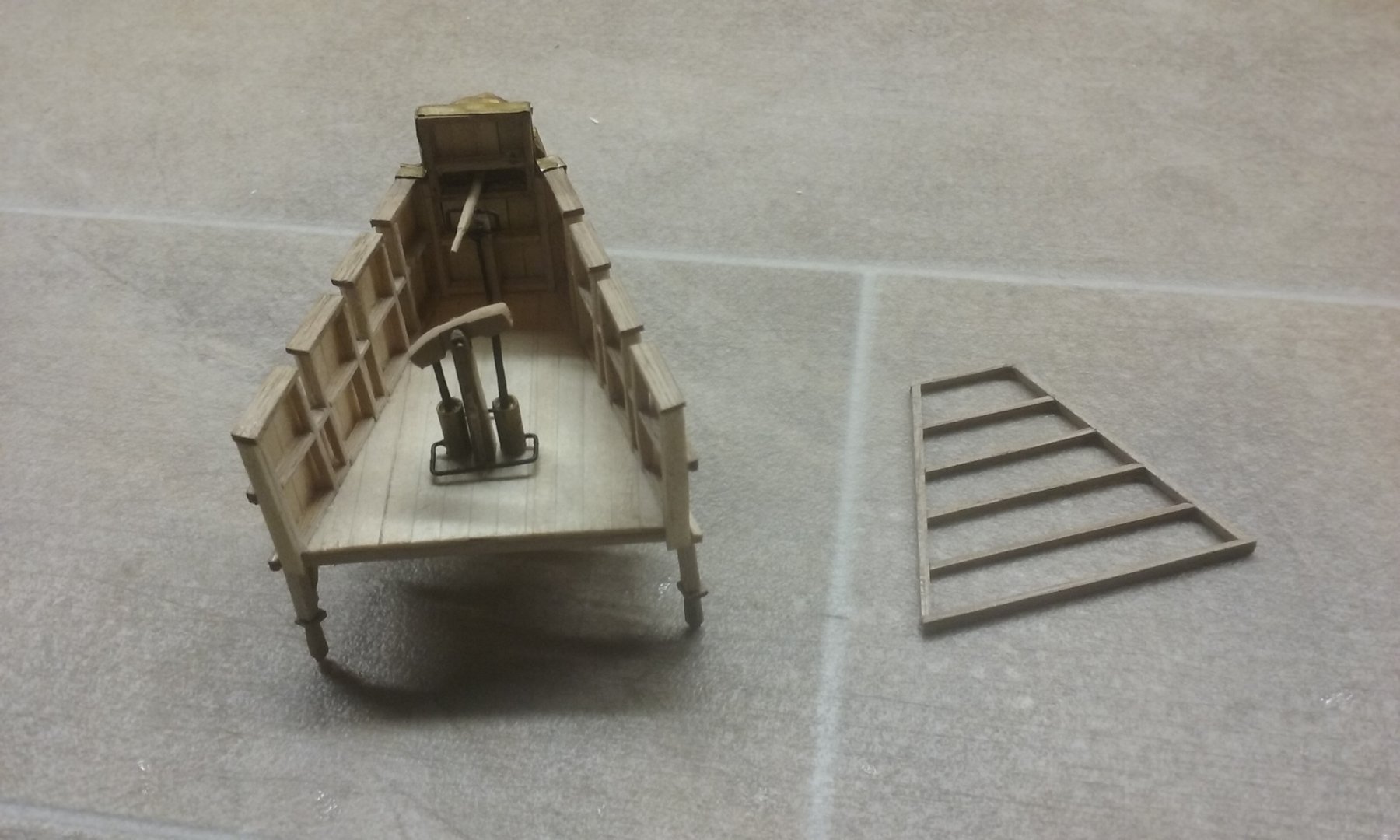
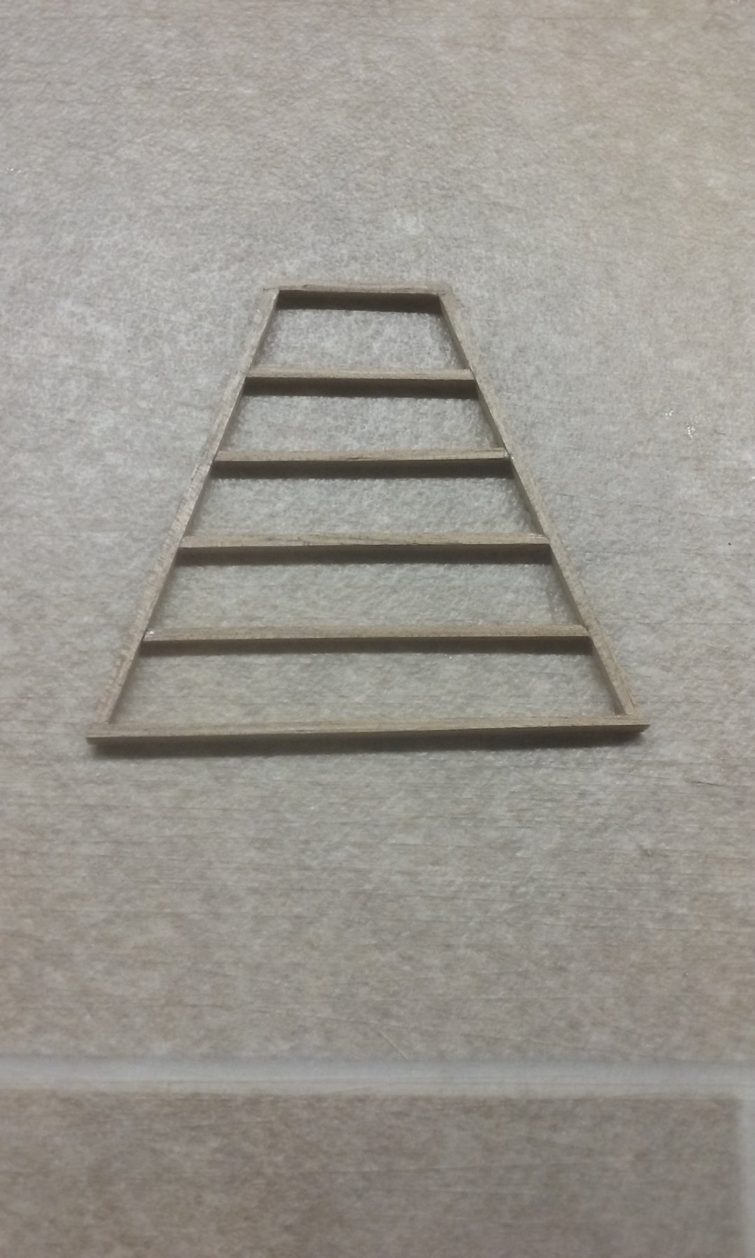
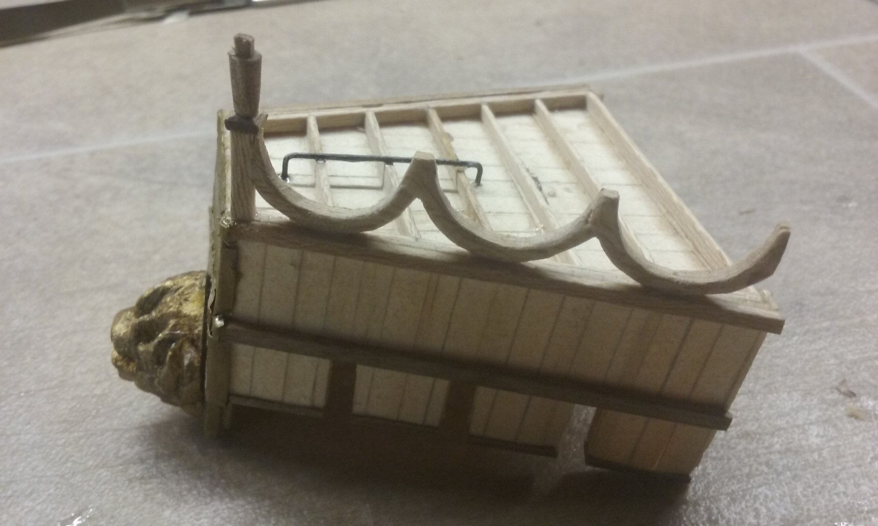
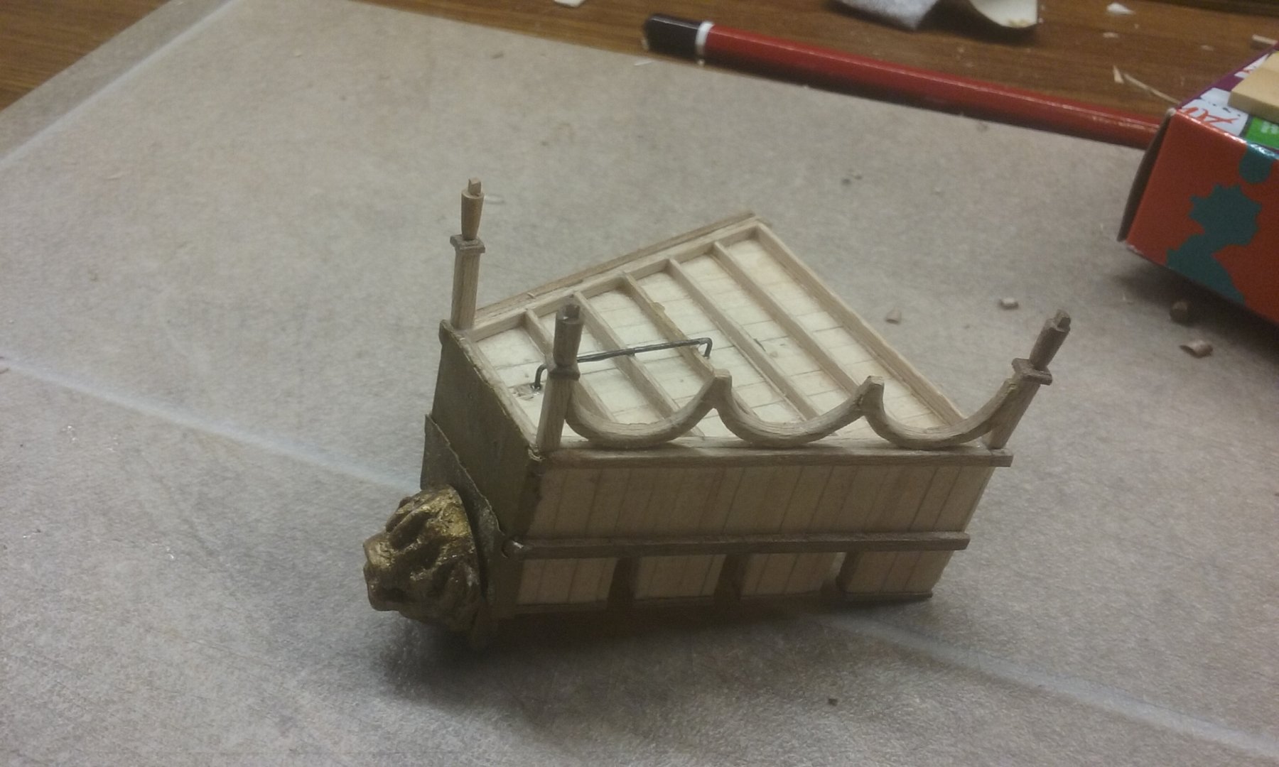
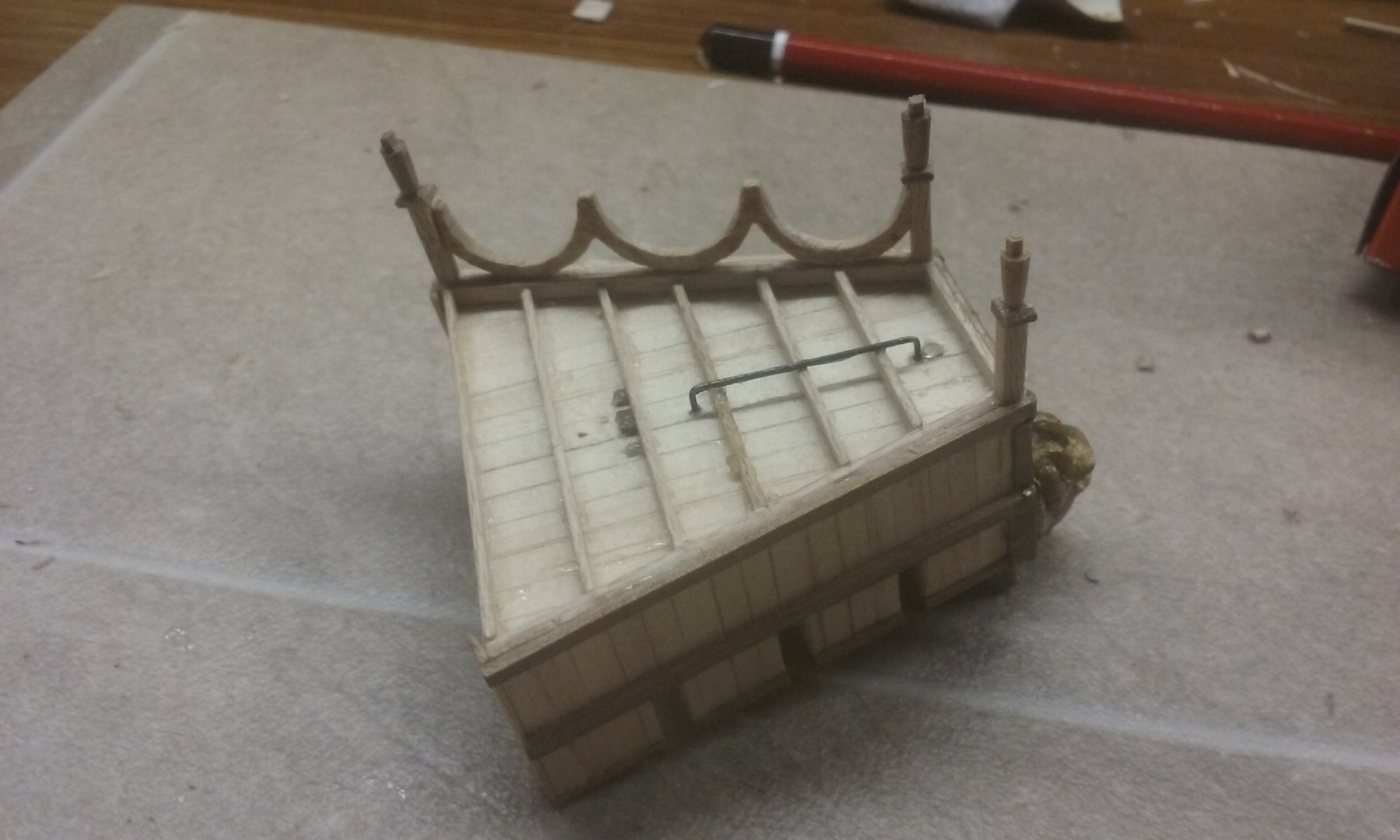
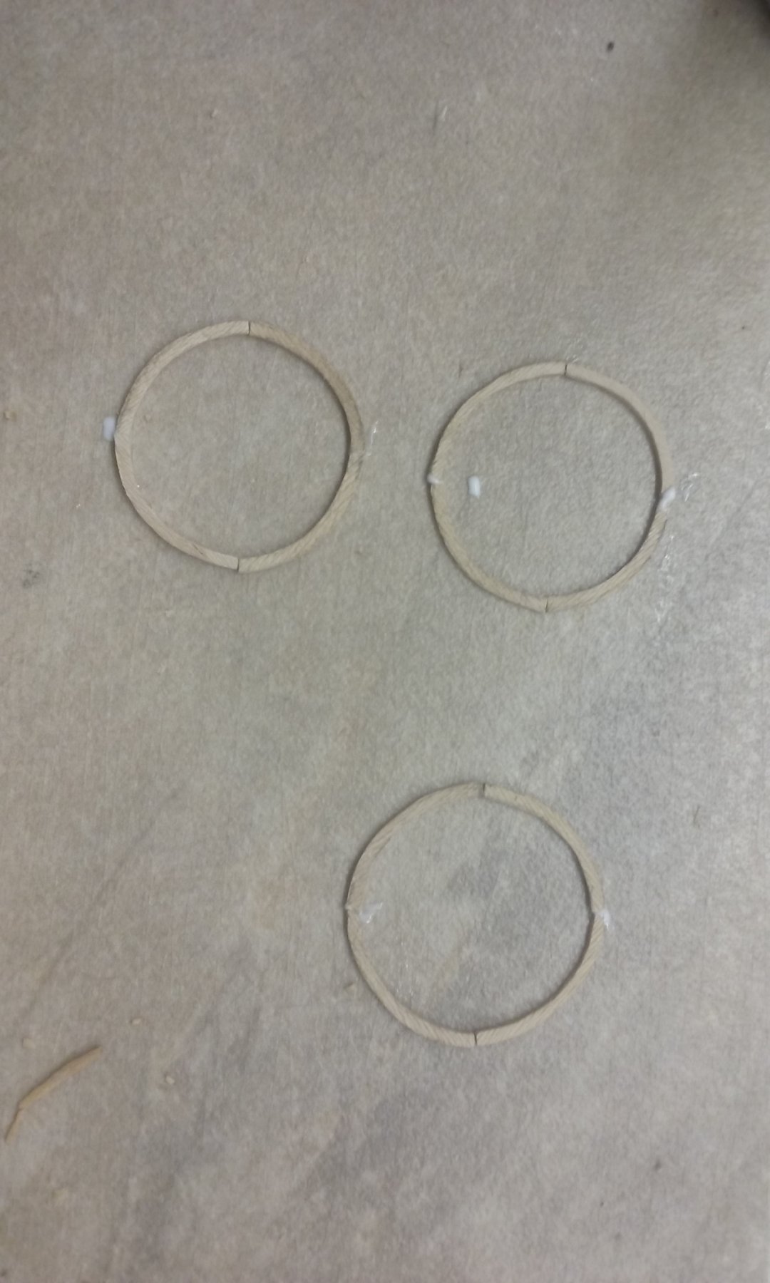
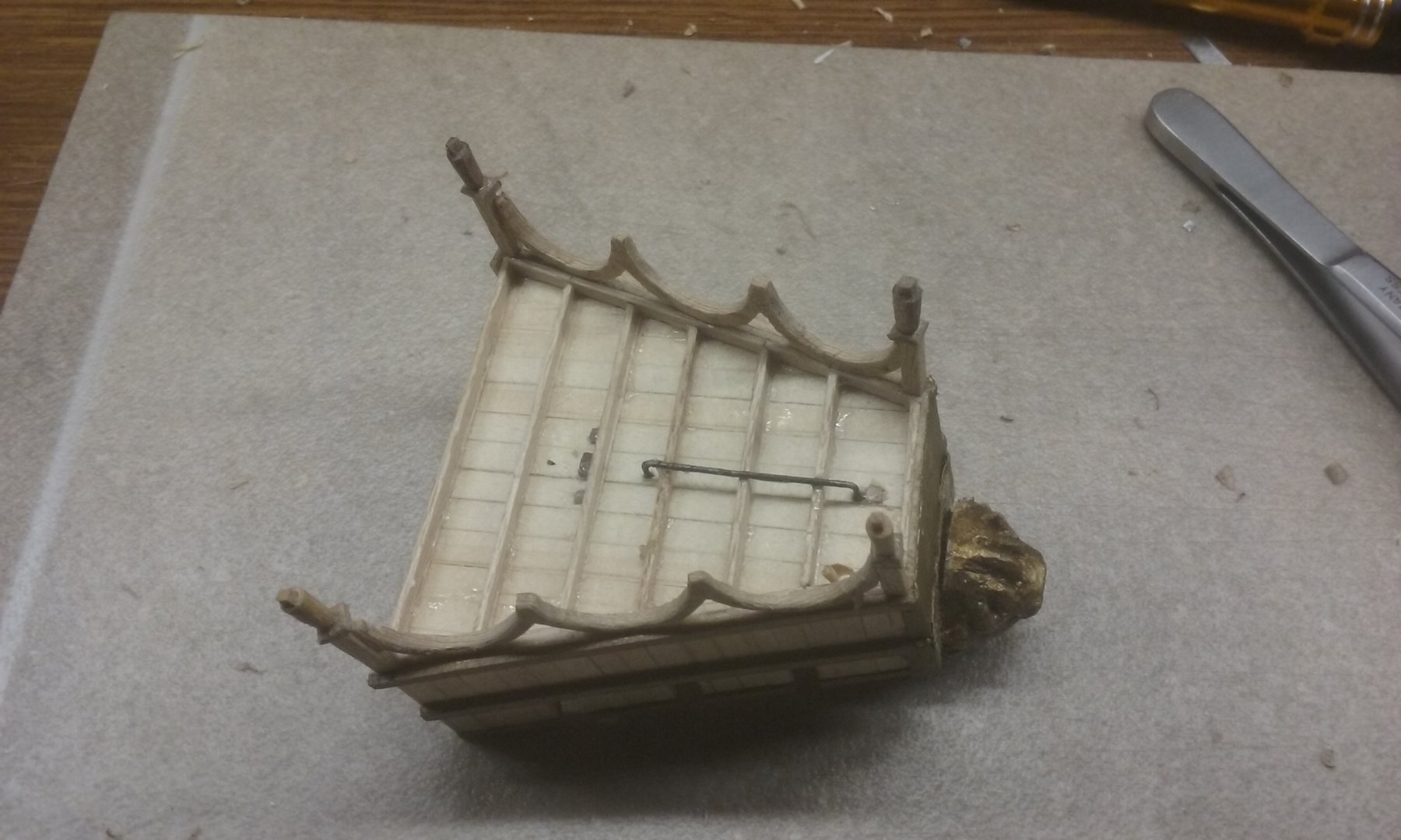
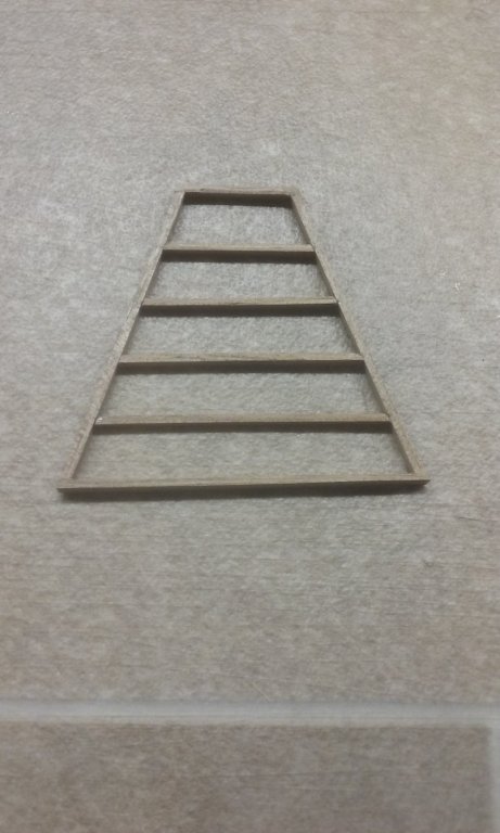
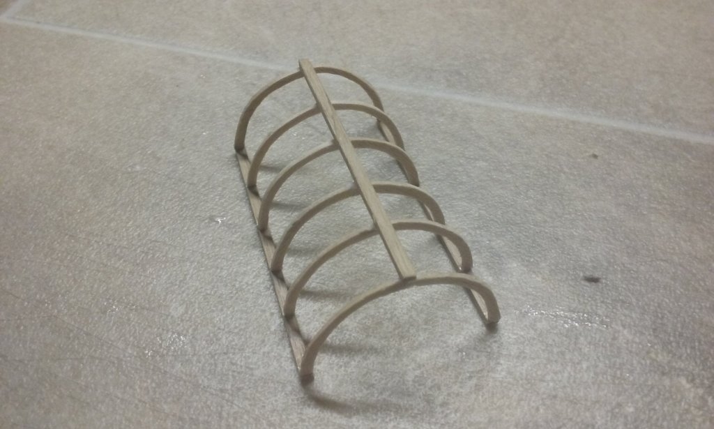
Forecastle complete except for intermediate columns, which will be added once it's in place on the ship. Arches for poop deck awning Framework done for awning. Support columns still to be made. Steven

-
Thanks Yancovitch - and yet, like you, I'm very aware of the faults in my own build that others don't seem to see . . .😉 Thanks Pat for the comments, and everybody for the likes. More to come. Steven
-
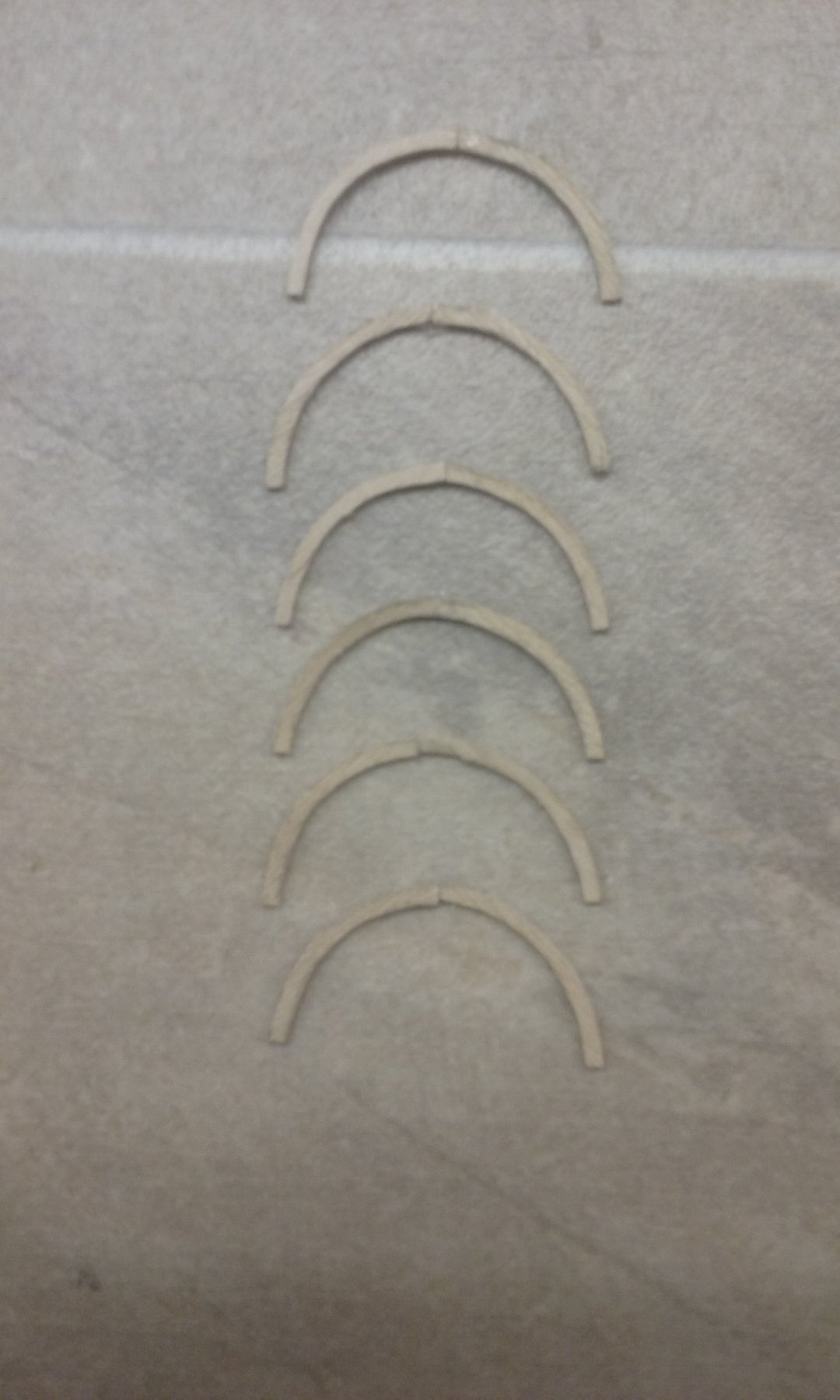
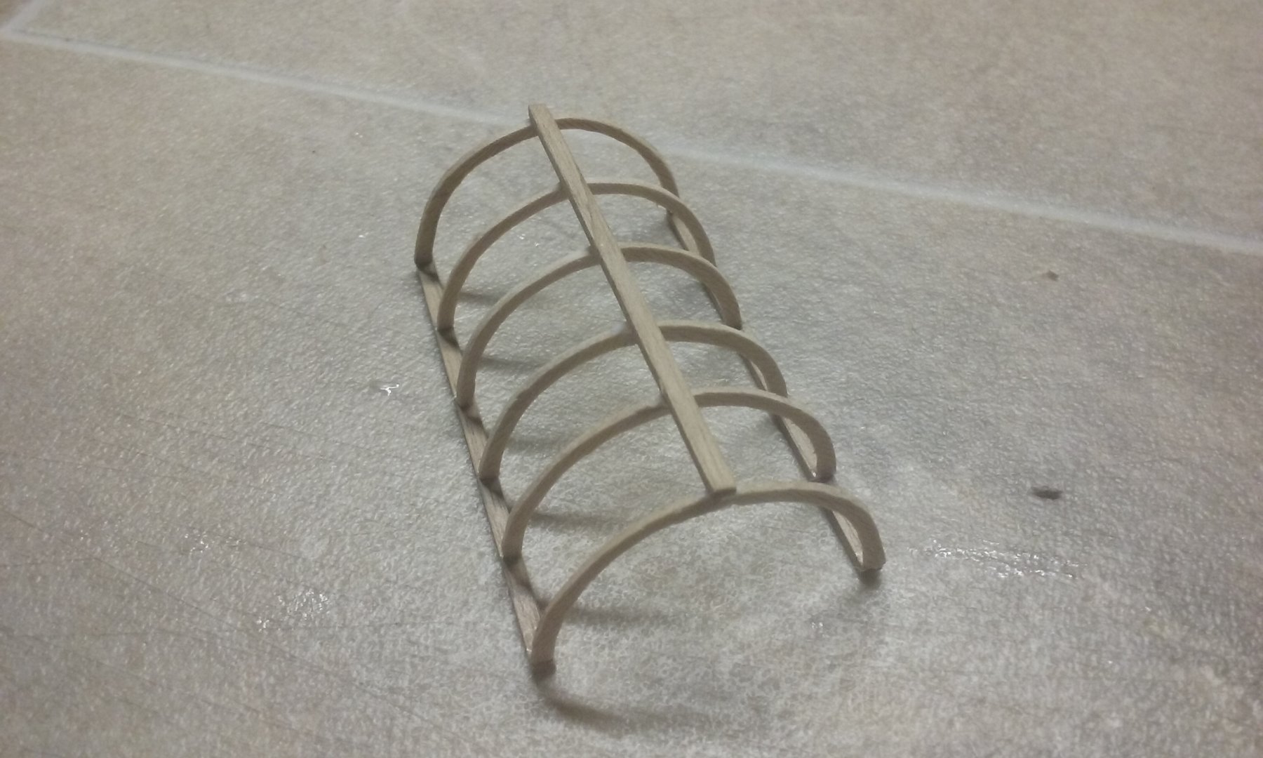
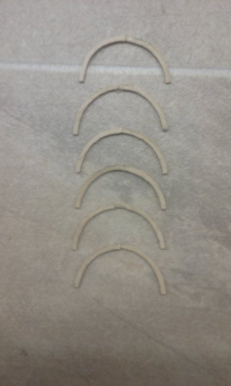
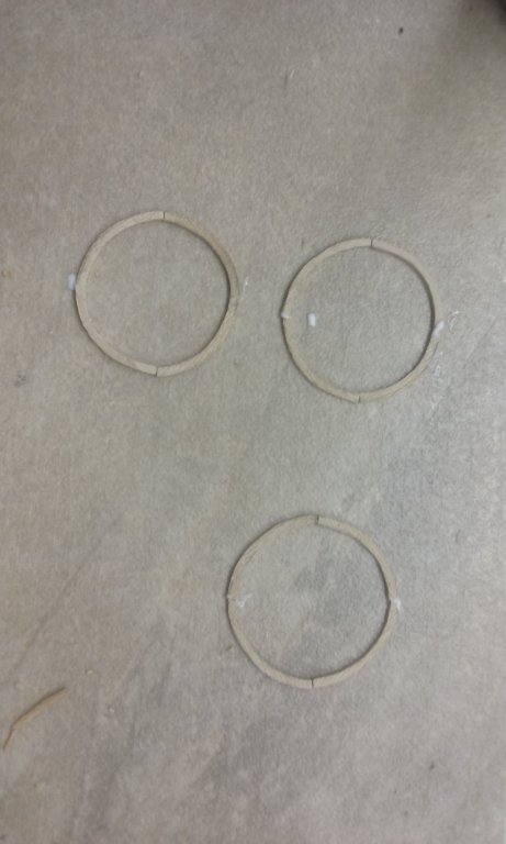
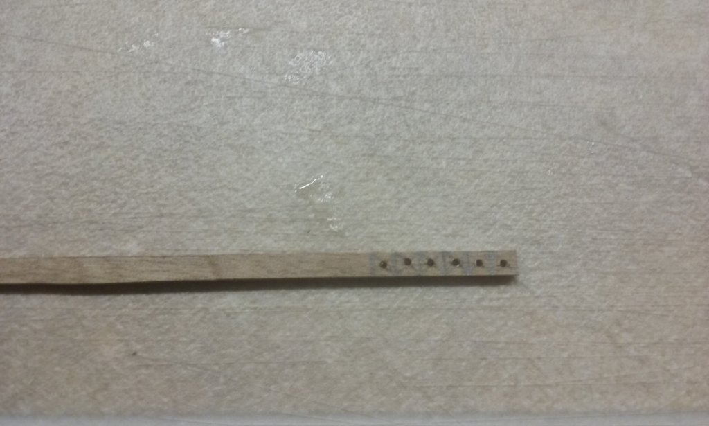
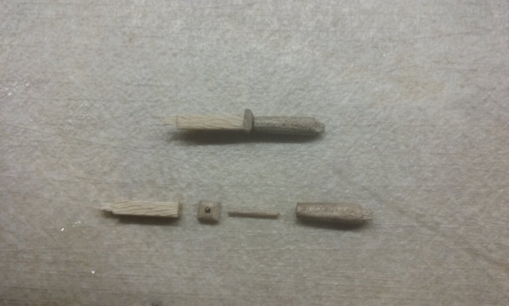
I've done the arcade substructure for the forecastle, incorporating lessons from my mistakes when I did the two side castles. The main things I'm doing different are leaving this bit till last as it's all rather delicate, and to fix the component parts with tenons or dowel joints, rather than rely on butt joints to keep everything in place. Here are the capitals for the columns below the arches. and the parts of the column/corner assembly - and the assembly - er - assembled Adding the first column/corner assembly and the arcades I won't be able to have tenons on the intermediate columns - there's note enough thickness in the arches, and I can't determine the locations of the bottoms precisely enough to put the mortises in place. So I'll be forced to put these in with butt joints, but that should be ok - they're subsidiary pieces and not truly structural. I've also made a start on the arches for the awning at the stern. Couldn't work out how to get a decent semicircle for each, until I thought - two of them make a circle, and a perfect/imperfect circle is much easier to spot than a perfect/imperfect semicircle. So I put six arches together in sets of two to form circles; much better. Steven


-
Beautiful work, Luponero. I am enjoying following this build. Naves of this time are of great interest to me. Steven
- 197 replies
-
- 2
-
-
- santa maria
- carrack
- (and 1 more)
-
I'm in the middle of a book called "War in a Stringbag" by the pilot who was the last to land on Glorious just before it was torpedoed and sunk, redeployed to Illustrious, took part in the Taranto raid, was in the air when Illustrious was heavily damaged by Stukas (which also tried to shoot him down) and had to fly to Malta to land, then the desert campaign and then Greece. That's as far as I've got so far, but fascinating reading. Steven
-
Thanks everybody for the likes. Christos, thanks for the comment. I wish I could speed it all up, but I have to fit it in with everything else I have to do, and it all takes time - more than I'd expected. The amount of time I've spent waiting for paint to dry, then glue to dry, you wouldn't believe!😁 Steven
-
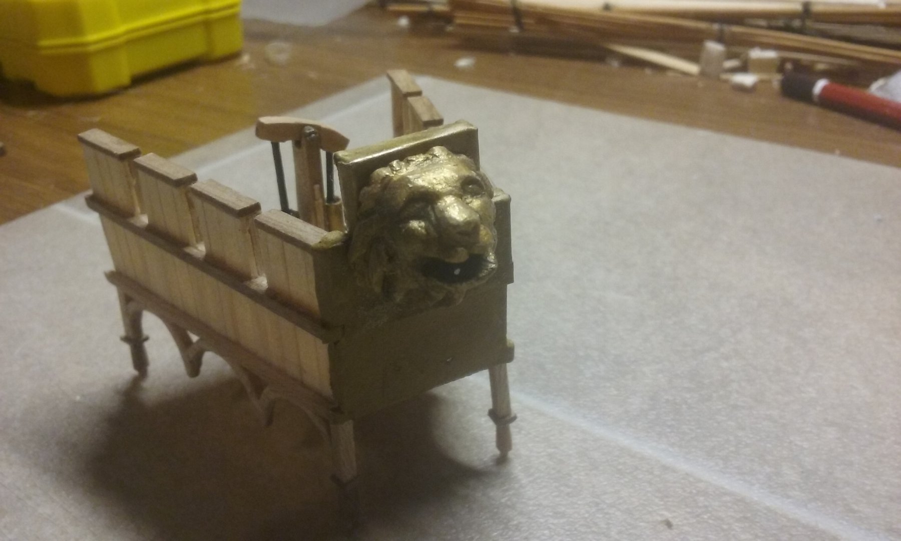
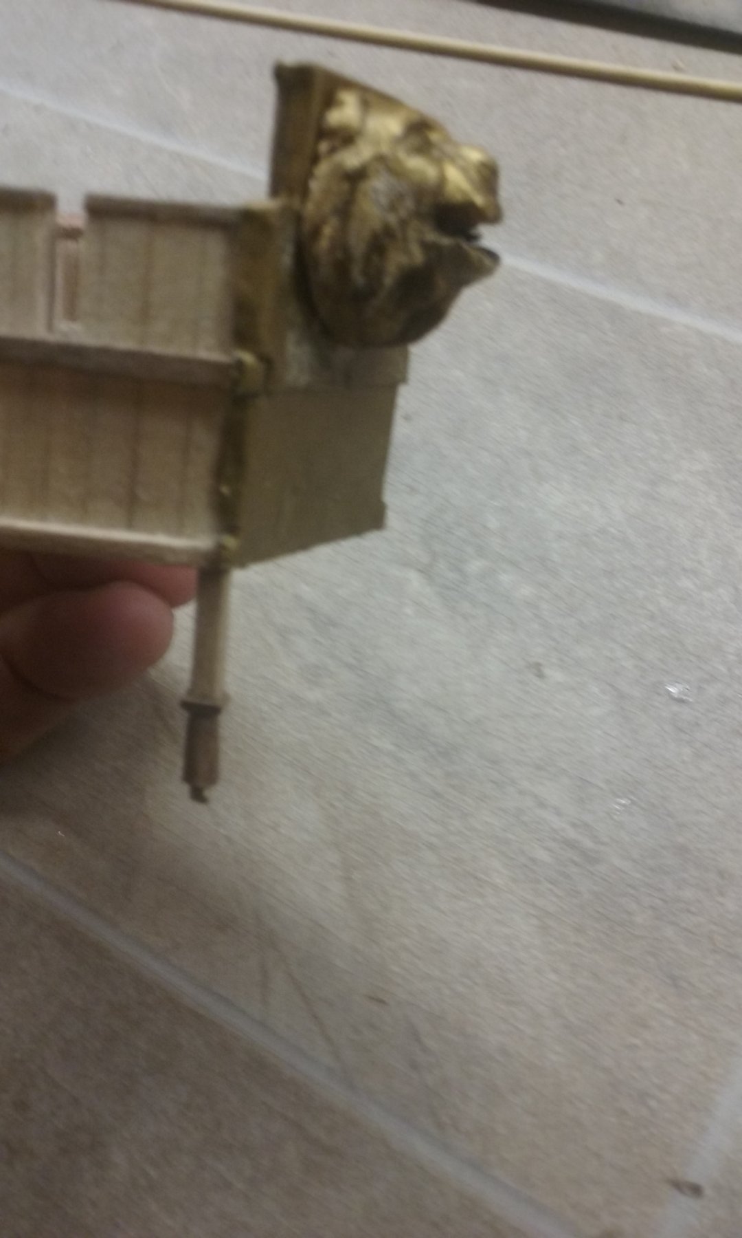
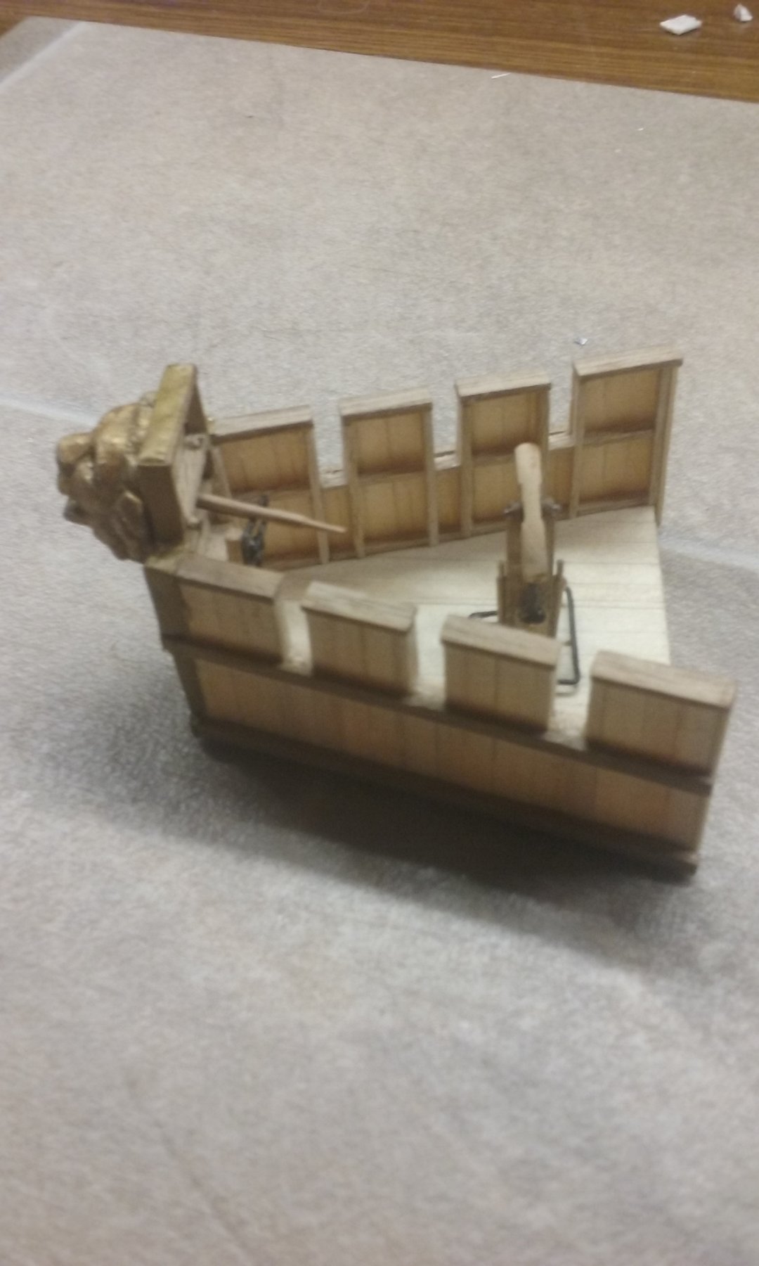
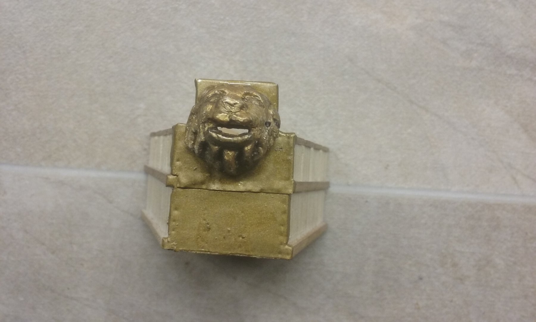
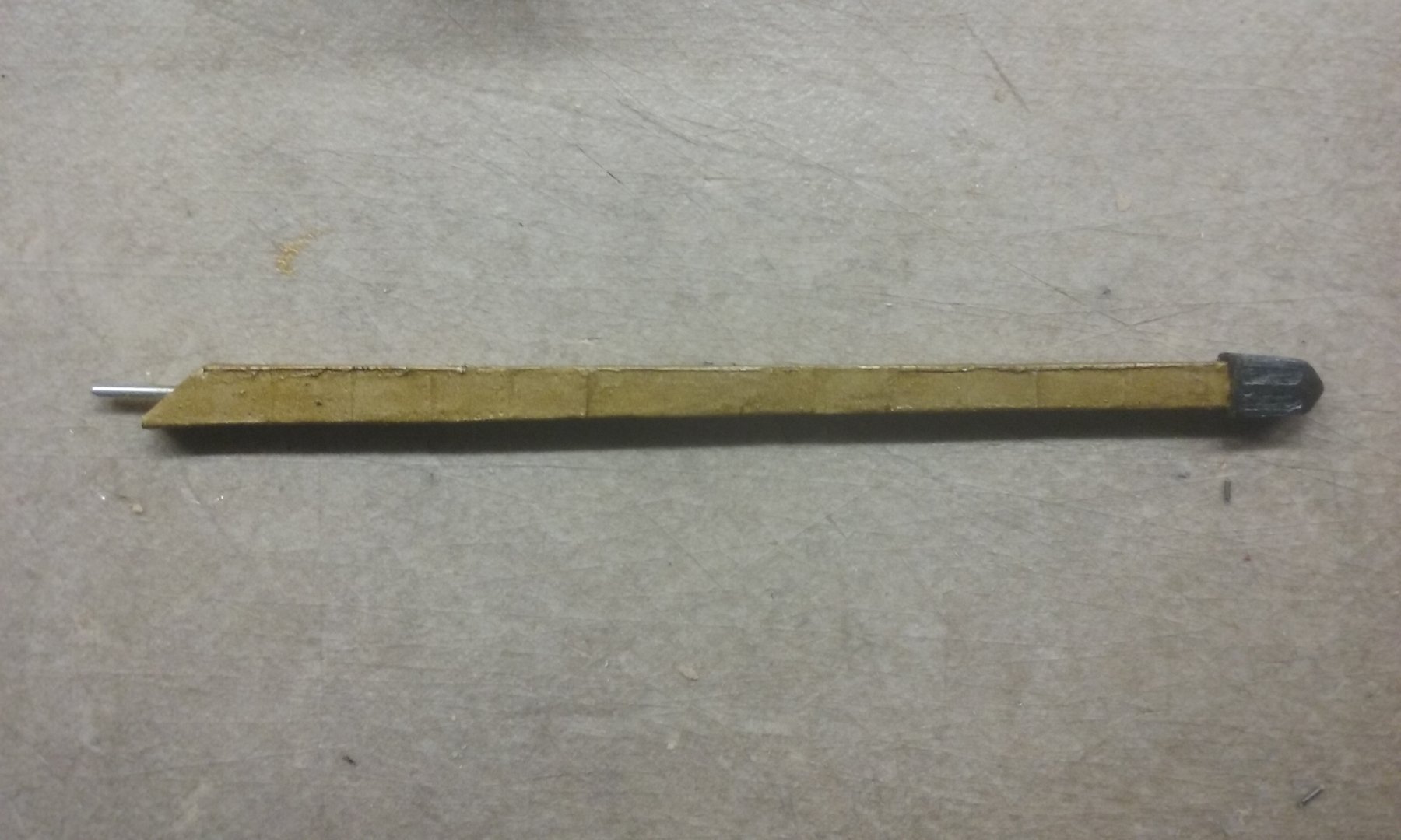
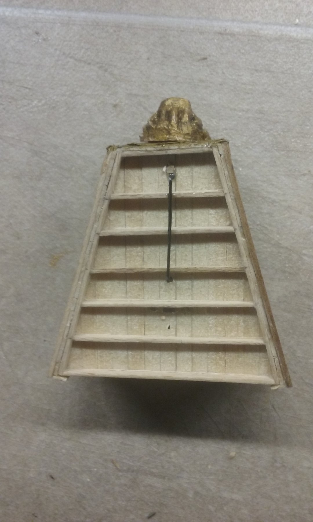
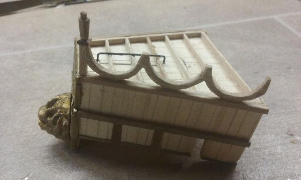
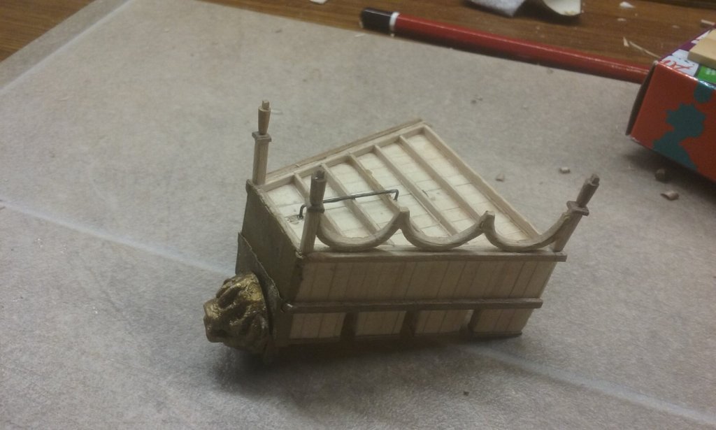
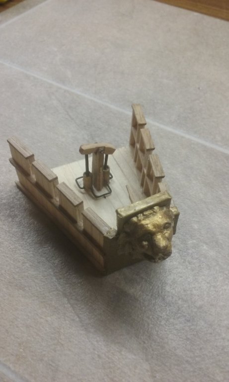
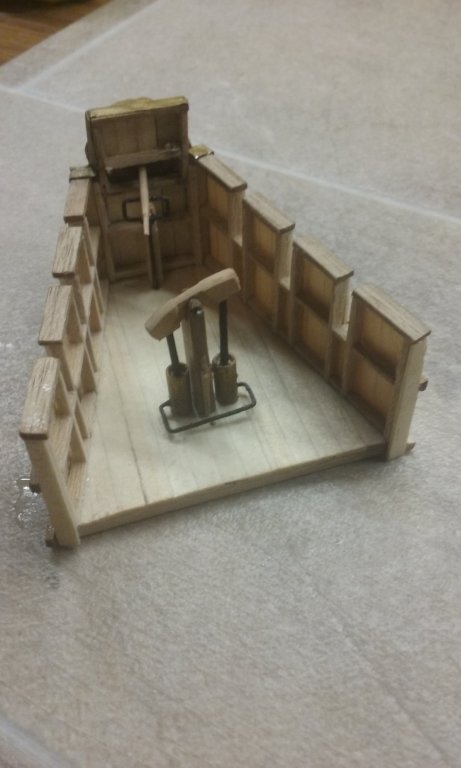
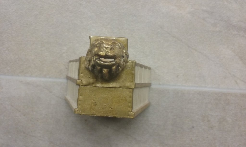
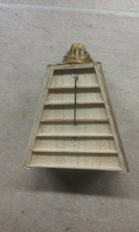
Just painted the "bronze" plates on the spur and the forecastle so they're the right colour. And added the "bronze" lion's head to the forecastle. Not too bad, but I'm sure I'll do better next time if I have to do something similar again. And installing the siphon on the forecastle is almost complete, with the nozzle passing through the lion's mouth. I've run a "pipe" under the deck between the pump and the riser. To finish the rest off I have to wait till I've finished the forecastle's arched substructure and the dry-fit the forecastle onto the ship, with the oil reservoir on the main deck below it, so I can install the "pipe" through the forecastle decking to connect the pump to the reservoir. Then it'll be ready to install (when I've done all the other things that need to be done to the ship before it goes in position). Making progress. Steven


-
Hmm, I might have been better cutting individual plates for the cladding and gluing them on separately. Steven
-
Thanks, Dick. Looking forward to seeing your interpretation in practice. Steven
- 263 replies
-
- 3
-
-
- nave tonda
- round ship
- (and 2 more)